Crystal Video Technology 306020180409 Wireless Video Transmission System User Manual
Shenzhen Crystal Video Technology Co.,LTD. Wireless Video Transmission System
User manual
BeamLink-Quad Wireless
Transmission System
天演无线图传
快速使用指南
Quick Start Guide
Version:1.0
深圳市视晶无线技术有限公司
深圳市宝安中心区宝源路F518时尚创意园F10-13栋
服务热线:400-6262-963
传真:+86-755-29188427
E-mail:Marketing@cv-hd.com
产品及配件自购买之日起保修一年
BeamLink-Quad ONE-YEAR LIMITED WARRANTY
邮编:518102
电话:+86-755-26716688
E-mail:Sales@cv-hd.com
Model:3060
H D M I
S D I H D M I
产品特色
支持四路HDMI和SDI输出,分辨率最高1080P/60
超低延时技术,可无缝对接各种类型的切播台
产品安装简单、操作便捷、应用灵活,免除多机位布线烦恼。
物品清单
产品包装内随附以下物品:
天线 *16
1/4英寸
螺母杆连接件 *4 电源线 *4
天线 *4 电源适配器 *1 安装底座 *1
发射机 *4
接收机 *1
说明:发射机自带Sony NP-F电池座并已预装V扣连接件;
接收机上已预装电池扣板和V扣连接件。
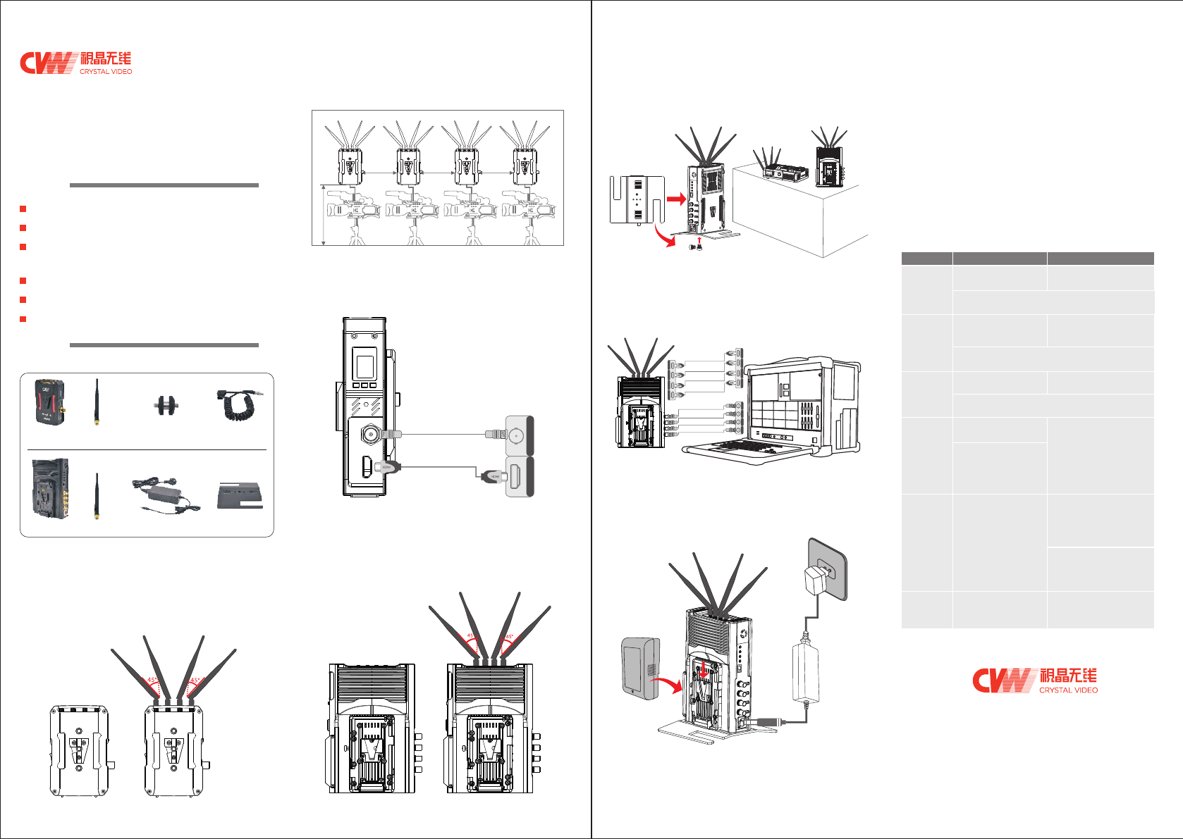
1. 请按图示将天线安装至发射机的天线接口,
呈扇形摆放。( 如下图所示)
发射机准备
间距>1米 间距>1米 间距>1米
距离地面>1.5-2米
3. 请将发射机和摄像机之间的高清视频线连接好。
( 如下图所示)
HDMI输入
SDI输入
步骤二 接收机准备
1. 请按图示将天线安装至接收机的天线接口,
并呈扇形摆放。( 如下图所示)
接收机放置在距离
地面1.5~2米高处
B:立式摆放
A:卧式摆放
利用机身底部的螺母孔
用2颗螺母进行固定安装
安装底座
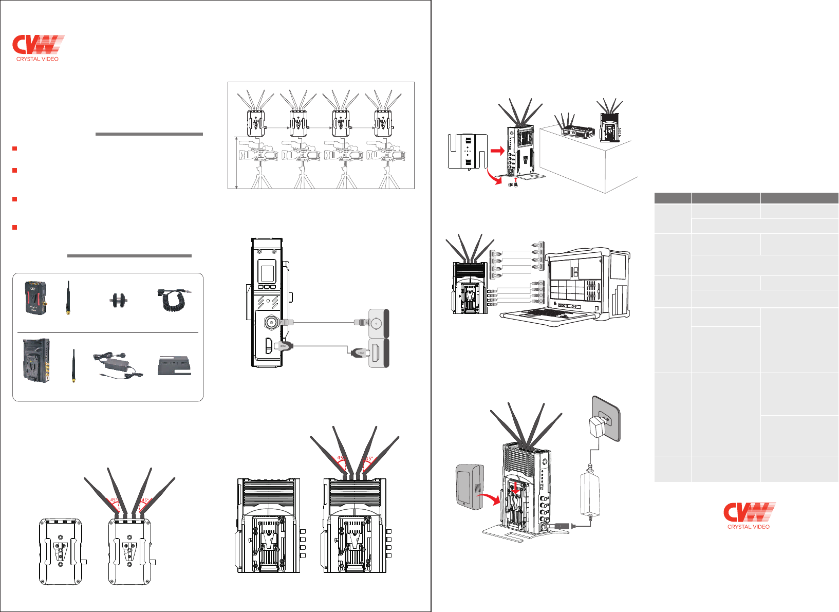
3. 请将接收机和导播台或监视器之间的高清视频线连接好。
00:00:00
SDI输出
SDI输出
SDI输出
SDI输出
4. 接收机可以通过电池扣板外挂V字型锂电池供电,也可以
通过卡侬口外接随附的电源适配器供电。如果同时接好
了两种供电方式,将优先使用锂电池供电,电池耗尽后
将自动切换至电源适配器供电。
锂电池
电源
请依次打开发射机、接收机和其它关联设备的电源开关,
上电后发射机和接收机的OLED屏点亮,发射机的指示灯
亮红灯。发射机与接收机进行WiFi连接时,发射机指示灯
切换至黄灯闪烁,WiFi连接成功后黄灯长亮,稍等片刻就
能在接收机连接的显示终端观看到实时图像。从产品上
电到显示实时图像预计花费1分半钟。
4台发射机和接收机的4路视频输出口是一一对应的,
OLED屏上显示设备号1的发射机,解码后的视频将通过
接收机背面丝印1处的视频口输出,其余类推。
步骤四 产品按键操作
使用情形 发射机 接收机
遇到干扰源
请切换
工作频点
通过短按【CH/WPS】按键可
在11个工作频点间循环切换
接收机切换工作频点后,
接收机和发射机的OLED屏都会显示当前频点号
近距离使用
时请使用
低增益模式
长按【LNA ON/OFF】
按键3秒进行高低增益
模式切换
发射机和接收机切换至低增益模式后,OLED屏上都会
显示“L”字符。如果切换回高增益模式该字符会消失。
长按【LNA ON/OFF】
按键3秒进行高低增益
模式切换
更换设备后
请重新对码 发射机和接收机在对码过程中,OLED屏上都会一直
显示”WPS“字符串,对码结束后该字符串消失。
长按【CH/WPS】
按键3秒启动对码
长按【CH/WPS】
按键3秒启动对码
发射机重启
编码板
长按【RESET】按键3秒
重启该发射机的编码板
编码板在重启过程中,
该发射机的OLED屏上会
一直显示“RESET”
字符串,重启结束后该
字符串消失
接收机重启
某一路
解码板
首先通过短按【RESET】
按键在1、2、3、4间循环
选择要重启的那一路解码板,
然后长按【RESET】
按键3秒确定重启。
解码板在重启过程中,
接收机的OLED屏上会一直
显示“RESET”字符串,
重启结束后该字符串消失
本系统支持Tally功能,请将发射机和接收机端的Tally线
连接好。当接收机被低电平触发后,发射机将输出高电
平信号。
HD M IHD M IH D M IHD M I
HDMI输出
HDMI输出
HDMI输出
HDMI输出
SD I SD I
HD M IHD M IH D M IHD M I SD I
SD I SD I
( 接收机支持4个SDI输出和4个HDMI输出 )
--
--
--
接收机切换
OLED显示
方向
短按【LNA ON/OFF】按键,
接收机的OLED将进行横屏和
竖屏显示切换。
--
此产品利用低延时H264编解码方案和5G WIFI方案,
完成四路高清视频的无线传输,四路信号只占用一路无线信道,
接收端将四路SDI或HDMI高清视频信号传到切播台。
空旷环境下传输距离500米
支持tally功能(接收机被低电平触发后,
发射机输出高电平信号)
发射机和接收机均支持电池供电
步骤一
2. 请将发射机通过机身底部的螺母孔或侧面V扣固定到距离
地面1.5~2米处的位置。多台发射机同时工作时请保证
发射机之间至少间距1米。( 如下图所示)
2. 请将接收机放置在距离地面1.5~2米高处。接收机可以
立放、卧放,并能通过机身底部的螺母孔或侧面V扣进
行固定安装。立式摆放前请先装上随附的底座。
( 如下图所示)
步骤三 产品开机 www.cv-hd.cn
感谢您选用CVW公司的专业级无线高清传输产品,
在使用产品前,请仔细阅读本使用说明
Place the receiver at a
height of around 1.5 to
2 meters above floor.
Distance> 1 m Distance> 1 m Distance> 1 m
Transmitter at a height of
around 1.5 to2 meters above floor.
Please turn on transmitter, receiver and other related devices
in turn. After powering on, the OLED panel on the transmitter
and the receiver will be lit up, and the status light of transmitter
will be lit red. When transmitter and receiver are on connecting
mode, the status light of transmitter will turn to flicker in yellow.
When the connection is successful, the status light of transmitter
will be on yellow steadily, then you will get live image at the
receiver side. It will take about 90 seconds from powering up
the product to the live image displaying.
There is a one-to-one correspondence between four transmitters
and four video output interfaces of the receiver, that is to say,
the video transmitted by the transmitter which shows No. 1 on
its OELD screen will be also output from the video out interface
marked No. 1 and can deduce the rest 3 transmitters from this.
Description of buttons operation
H D M I
S D I H D M I
HDMI In
SDI In
install the
affiliated metal stand
00:00:00
Power
Usage
Scenario Transmitter Receiver
Long press button “LNA ON/
OFF” for 3 seconds to switch
high or low gain mode.
HD M IHD M IH D M IHD M I
HDMI Out
SD I SD I
HD M IHD M IH D M IHD M I SD I
SD I SD I
--
--
--
3. Please connect the transmitter and camera with SDI or
HDMI cable.
Receiver Installation
1. Please install all the antennas on the receiver, and make them
in a fan shape as shown in the picture.
3. Please connect the receiver and video switch console or
monitor with SDI or HDMI cable.
HDMI Out
HDMI Out
HDMI Out
SDI Out
SDI Out
SDI Out
SDI Out
4. The receiver can be powered by both the
and DC-IN port via the affiliated power adapter. If the mentioned
two types of powersupply are connected at the same time,
the lithium battery should be prioritized in power supplying,
and the battery will switch to the power adapter for power
supplying automatically after the battery power is exhausted.
V-mount battery
This system supports tally function. When the receiver is
activated by low-level current, the transmitter will output
high-level current signal.
Short press button “CH/WPS” to
switch among 11 channels circularly.
After switching the channel, the OLED screen of transmitter and
receiver will both display current working frequency.
Please choose
low gain mode
when works in
short distance.
Switching
to a different
channel when
there is
interference.
After switching into low gain mode both on transmitter and
receiver sides, the OLED screen will display an “L” letter.
If switching back to high gain mode, the letter will disappear.
Please re-pair
the kits after
you replace
receiver or
transmitter
Long press button “CH/WPS”
for 3 seconds to start paring.
Long press button “CH/WPS”
for 3 seconds to start paring.
When transmitter and receiver are in the process of paring,
the OLED screen will display character string “WPS”,
and the character string will disappear after paring is successful.
Reset video
encoder
Long press button “RESET”
for 3 seconds to reset the
video encoder of transmitter.
When the video encoder is on
resetting, the OLED screen of
this transmitter will keep
displaying the character
string “RESET”, and the
character string will disappear
after resetting is finished.
Reset specific
video decoder
on receiver.
First, short press button“RESET”
to choose the video decoder
which you need to reset from the
symbol as 1, 2, 3, 4 on OLED
screen of receiver , then long
press button “RESET” for 3
seconds to confirm resetting.
When video decoder is in the
process of resetting, the OLED
screen of receiver will keep
displaying character string
“RESET”, and the character
string will disappear after
esetting is finished.
Switch OLED
display direction
of receiver
Short press button “LNA ON/OFF”
and the OLED display direction of
receiver will be switching between
horizontal and vertical modes.
--
Long press button “LNA ON/
OFF” for 3 seconds to switch
high or low gain mode.
Li-battery
Thank you for buying CVW product--BeamLink-Quad,
PRODUCT FEATURES
Support 4 Tx-to-1 Rx; tally function; support 4 channels HD
video transmission simultaneously in ONLY 1 RF channel;
8Mbps date rate for each video channel, support 4 channels
video transmission simultaneously in up to 500 meters
range with 150mS latency;
Support 4 channels video input & output through SDI or
HDMI interface. The system can be connected seamlessly
to most popular video switch consoles.
2. Please fix the transmitter via the screw at the bottom or the
V-mount at the back, and place it at a height of around 1.5 to
2 meters above floor. Please make sure that the distance
between each transmitter is more than 1 meter.
2. Please place the receiver at a height of around 1.5 to 2 meters
above floor. Receiver can be placed in vertical or horizontal
positions, and can be fixed via the screw at the bottom or
V-mount at the back. Please install the affiliated metal stand
before placing the receiver in vertical position.
B: Vertical placement
A: Horizontal placement
Power up and start to use
Antenna
* 16 pieces
1/4 inch screw &
nut connector*4 pieces
Antenna
* 4 pieces Power adapter*1 piece Metal Stand*1 piece
Transmitter
* 4 pieces
Receiver
* 1 piece
www.cv-hd.com
Simple installation; convenient operation; flexible application;
eliminate the hassel of running wires across multi-camera
positions.
PACKING LIST
The following items are included in the product package:
Power supply cable
*4 pieces
Notice: The transmitter comes with the Sony NP-F type battery
plate and has preassembled V-mount connector. The receiver
has preassembled battery plate and v-mount connector.
Transmitter Installation
1. Please install all the antennas on the transmitter and make
them in a fan shape as shown in the picture.
the product adopt the low latency H264 coding-and-
decoding scheme and 5G WiFi solution.
the 4 Transmitters-to-1 Receiver wireless HD video
transmission system. Please read the instructions
carefully before using the product.

This equipment has been tested and found to comply with the limits for a Class B digital device, pursuant to part 15 of the FCC Rules.
These limits are designed to provide reasonable protection against harmful interference in a residential installation.
This equipment generates, uses and can radiate radio frequency energy and, if not installed and used in accordance with the
instructions, may cause harmful interference to radio communications. However, there is no guarantee that interference will not
occur in a particular installation. If this equipment does cause harmful interference to radio or television reception, which can be
determined by turning the equipment off and on, the user is encouraged to try to correct the interference by one or more of the
following measures:
Reorient or relocate the receiving antenna.
Increase the separation between the equipment and receiver.
Connect the equipment into an outlet on a circuit different from that to which the receiver is connected.
Consult the dealer or an experienced radio/TV technician for help.
FCC Statement
This device complies with FCC radiation exposure limits set forth for an uncontrolled environment and it also complies with Part 15
of the FCC RF Rules. This equipment must be installed and operated in accordance with provided instructions and the antenna(s)
used for this transmitter must be installed to provide a separation distance of at least 20 cm from all persons and must not be
co-located or operating in conjunction with any other antenna or transmitter. End-users and installers must be provided with
antenna installation instructions and consider removing the no-collocation statement.
FCC Radiation Exposure Statement
This device complies with Part 15 of the FCC Rules. Operation is subject to the following two conditions:
(1) this device may not cause harmful interference, and
(2) this device must accept any interference received, including interference that may cause undesired operation.
Any changes or modifications not expressly approved by the party responsible for compliance could void the user's authority
to operate the equipment.
Caution!