CyberTAN Technology NU260HS 2.4G Module User Manual
CyberTAN Technology Inc. 2.4G Module
Contents
- 1. 8. User Manual
- 2. User Manual
User Manual
COMPANY CONFIDENTIAL
1
IEEE 802.11b/g/n WLAN and Bluetooth Combo Card
Project Name Marvell 88W8797 WLAN/BT Combo Card
Customer Hisense
Foxconn Part No. M26H003.00
Customer Part No. TBD
HON HAI PRECISION IND. CO., LTD.
No.2, 2nd Dong Huan Road, 10th
YouSong lndustrial District, Longhua
Town, Baoan, ShenZhen
Tel: +86-755-28128988#80633
Fax:
+86
-
755
-
28129800#64886
Product Specification

COMPANY CONFIDENTIAL
2
C
ONTENTS
0. REVISION HISTORY
1. INTRODUCTION
1.1
S
COPE
1.2
F
EATURE
1.3
A
PPLICATION
2. MECHANICAL SPECIFICATION
2.1
M
ODULE
D
IMENSION
2.2
H
OST
I
NTERFACE
C
ONNECTOR
2.3
RF
C
ONNECTOR
(O
PTION
)
3. ELECTRICAL SPECIFICATION
3.1
O
PERATING
C
ONDITION
3.2
W
I
F
I
RF
S
PECIFICATION
3.2.1 802.11b Mode
3.2.2 802.11g Mode
3.2.3 802.11n HT20 Mode
3.2.4 802.11n HT40 Mode
3.3
O
N
-
BOARD
A
NTENNA
S
PECIFICATION
3.3
BT
RF
S
PECIFICATION
4. COMPATIBILITY AND CERTIFICATION INFORMATION
5. QUALITY
6. APPENDIX
A
PPENDIX
A
-
L
ABEL
I
NFORMATION
A
PPENDIX
B
-
P
ACKAGE
I
NFORMATION

COMPANY CONFIDENTIAL
3
0. Revision History
Date Document
revision
Product
revision Change Description
2012/11/20
00 1. Initial release
2013/06/06
01 1. add label and package information
2013-10-17
02 Update PCB bottom view picture
(add FCC label)
COMPANY CONFIDENTIAL
4
1. Introduction
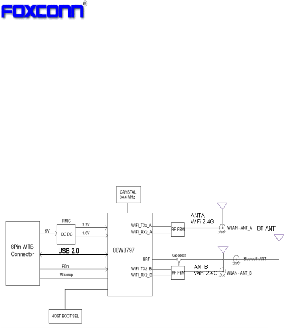
Project Name: Marvell 88W8797 WLAN/BT Combo Card
Project Number: M26H003.00
This documentation describes the engineering requirements specification of 88W8797
(WLAN+BT) combo Card. It is a confidential document of Foxconn.
1.1 Scope
This combo design is based on the Marvell 8797 single-chip solution. It’s operating in
2.4GHz, compatible with the IEEE 802.11b/g/n standard and Bluetooth BT4.0 standard.
The 802.11n data rate provides for MCS0 to MCS7 (HT20,HT40). The 802.11g data rate
provides for 54, 48, 36, 24, 18, 12, 9, 6Mbps, and 802.11b data rate provides for 11, 5.5,
2, 1Mbps. In addition, it’s also compatible with BT4.0. This combo card has implemented
some efficient mechanisms in its software and hardware to maximize the performance of
WLAN and BT.
1.2 Feature
Compatible with IEEE 802.11b/g/n standard
Compatible with BT4.0 + HS (supports Low Energy (LE)
Support external or on-board antenna for both WiFi and BT
Support two Antennas (WiFi*2 and BT shared one ANT)
or three antennas for WiFi *2 and BT*1 ( preferred )
2x2 MIMO spatial streams supporting data rates up to MCS15(300Mbps)
Better WiFi and BT Coexistence performance
COMPANY CONFIDENTIAL
5
1.3 Application
WLAN/Bluetooth/FM enabled cellular handsets
Portable audio/video devices and accessories
Personal computing systems including pads, tablets and slates
Wireless home audio and video entertainment systems including TV, set-top boxes,
media servers and gaming platforms
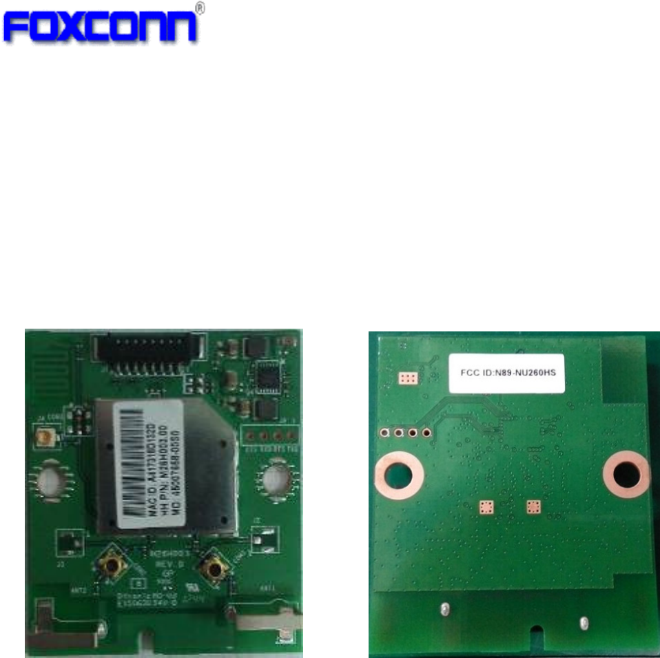
Sample picture as bellow
TOP VIEW BOTTOM VIEW
* note1, the sample picture is just for reference only.
COMPANY CONFIDENTIAL
6
2. Mechanical Specification
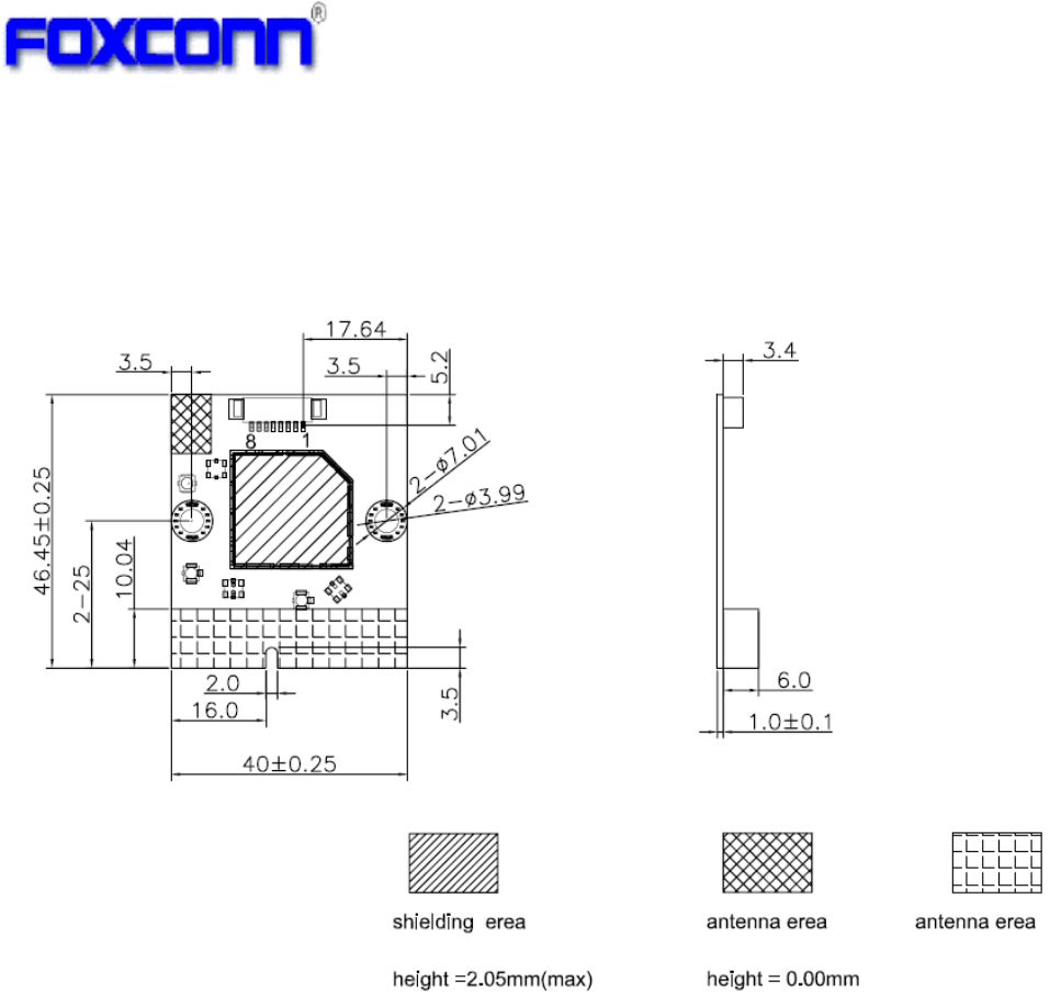
2.1 Module Dimension
PCB: FR4, 4layers, one side design
Typical PCB size (W×L): 40mm ×46.45mm
Unit: mm
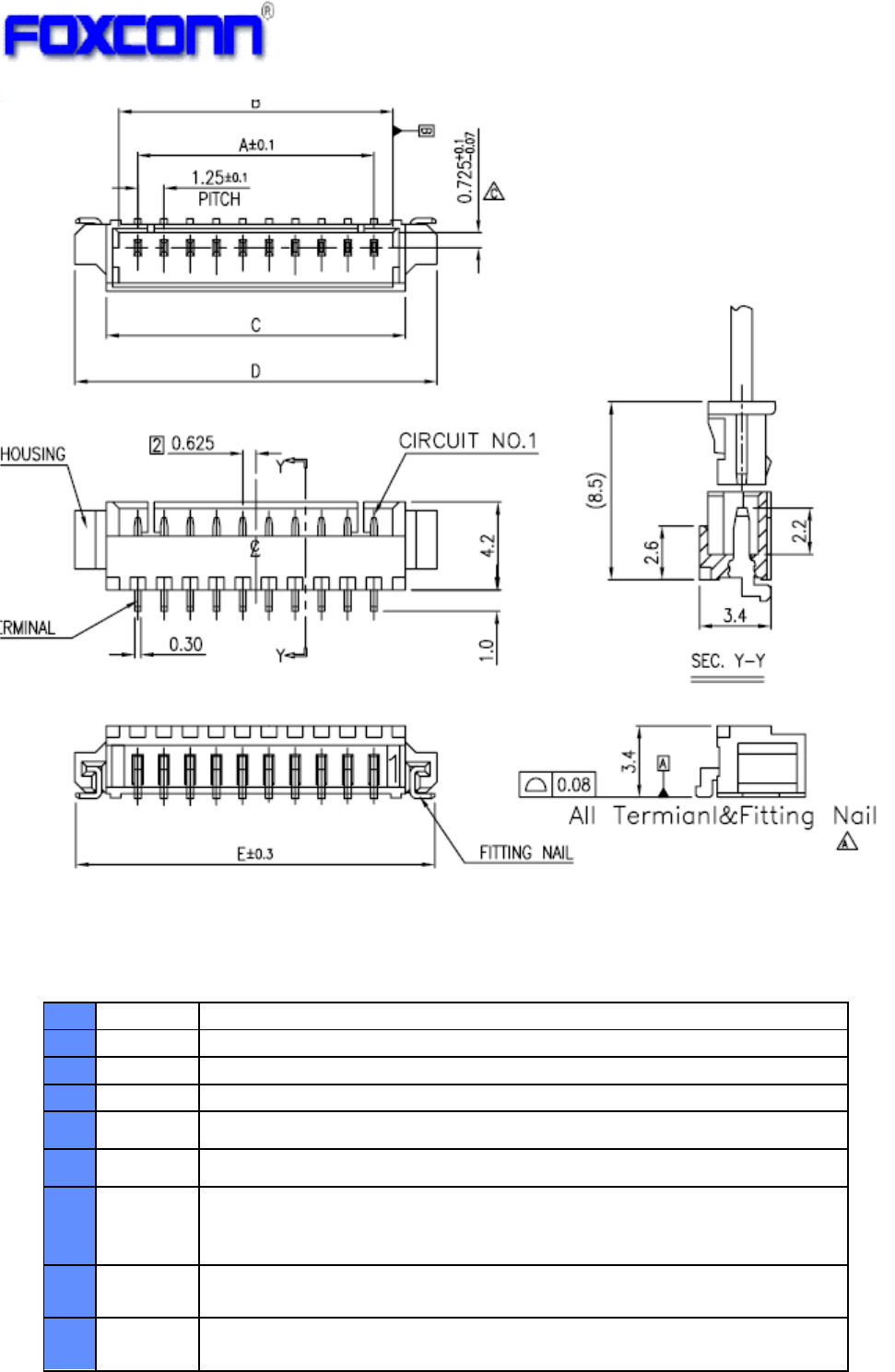
2.2 Host Interface Connector
This module use 8pins BTW connector for the Host-Module interface.
WTB 8Pin 1.25mm pin pitch SMD MALE
COMPANY CONFIDENTIAL
7
Here is the pin-out signals of module’s connector. The pin number is refer to
“Item2.2.1 module dimension”.
Table 1: Host-Module Connector Pin-out Signals
No.
Pin-Out Description
1
VCC
VCC 5V
2 GND GND
3 DN USB Data DN
4 DP USB Data DP
5 GND GND
6 Reset Reset (active low, input)
Once asserts low, all digital logic in the chip is reset to default
power up states. This pin has internal pull-up resistor on module.
7 Wakeup GPIO interrupt (host-to-chip wakeup interrupt) (input) (default)
Host Wakeup: chip-to-host wakeup interrupt (output)
8 PDn Full Power Down (active low, input)
This pin has internal pull-up resistor on module.
COMPANY CONFIDENTIAL
8
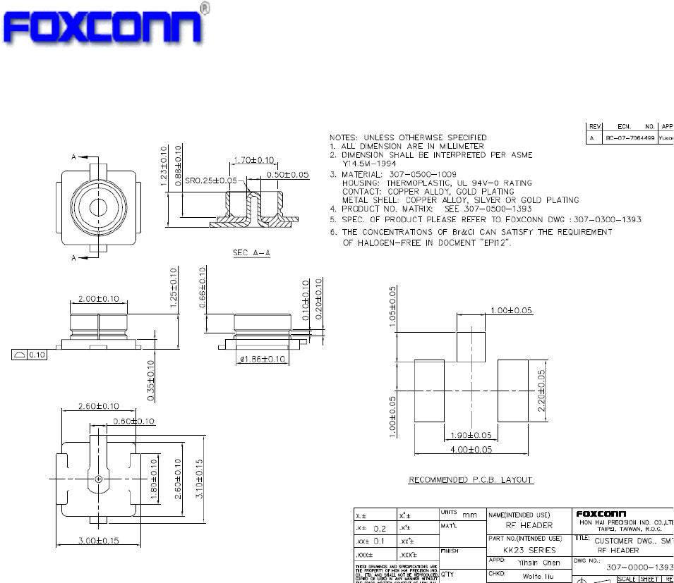
2.3 RF Connector (Option)
This module use U.F.L type RF connector for external WiFi/BT antenna connecting.
COMPANY CONFIDENTIAL
9
3. Electrical Specification
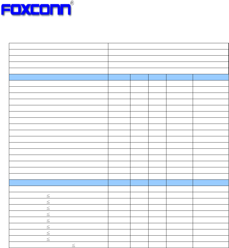
3.1 Operating Condition
Parameter Condition Min. Typ. Max. Unit
DC Input 5V 4.5 5 5.5 V
Module Current
(DC input nominal)
WiFi TX only and BT sleep 200 mA
WiFi RX only and BT sleep 176
BT TX only 172
BT RX only 181
WiFi/BT co-existence 220
Standby
with connection AP
180
Operating Temperature -- 0 +60
Storage Temperature -- -30 +85
3.2 WiFi RF Specification
3.2.1 802.11b Mode
Items
Contents
Standard IEEE802.11b
Modulation Type DSSS / CCK
Frequency range 2412MHz~2472MHz
Channel CH1 to CH13
Data rate 1, 2, 5.5, 11Mbps
TX Characteristics(per chain) Min.
Typ. Max. Unit
1. Transmitter Output Power
1) 11b Target Power 15 17 19 dBm
2. Spectrum Mask @ target power
1) fc +/-11MHz to +/-22MHz -30 dBr
2) fc > +/-22MHz -50 dBr
3. Frequency Error -25 -1 25 ppm
4 Constellation Error( peak EVM)@ target power
1) 1~11Mbps -31 dB
RX Characteristics(per chain) Min.
Typ. Max. Unit
5 Minimum Input Level Sensitivity
1) 1Mbps (FER 8%) -97.6 -83 dBm
2) 2Mbps (FER 8%) -94.4 -80 dBm
3) 5.5Mbps (FER 8%) -92.6 -79 dBm
4) 11Mbps (FER 8%) -89.0 -76 dBm
6 Maximum Input Level (FER 8%) -10 dBm
COMPANY CONFIDENTIAL
10
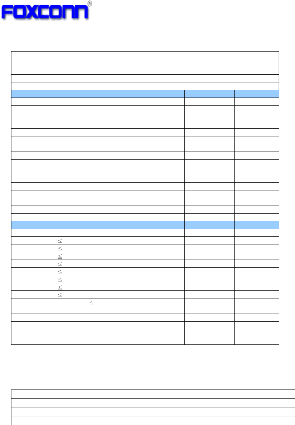
3.2.2 802.11g Mode
Items
Contents
Standard IEEE802.11g
Modulation Type OFDM
Frequency range 2412MHz~2472MHz
Channel CH1 to CH13
Data rate 6, 9, 12, 18, 24, 36, 48, 54Mbps
TX Characteristics (per chain) Min. Typ. Max. Unit
1. Transmitter Output Power
1) 11g Target Power 13 15 17 dBm
2. Spectrum Mask @ target power
1) at fc +/- 11MHz -20 dBr
2) at fc +/- 20MHz -28 dBr
3) at fc > +/-30MHz -40 dBr
3 Constellation Error(EVM)@ target power
1) 6Mbps -5 dB
2) 9Mbps -8 dB
3) 12Mbps -10 dB
4) 18Mbps -13 dB
5) 24Mbps -16 dB
6) 36Mbps -19 dB
7) 48Mbps -22 dB
8) 54Mbps -33 -25 dB
4 Frequency Error -25 -1.1 +25 ppm
RX Characteristics (per chain) Min. Typ. Max. Unit
5 Minimum Input Level Sensitivity
1) 6Mbps (PER 10%)
-
90.8
-85 dBm
2) 9Mbps (PER 10%)
-
90.3
-84 dBm
3) 12Mbps (PER 10%)
-
88.1
-82 dBm
4) 18Mbps (PER 10%) -86.2 -80 dBm
5) 24Mbps (PER 10%) -83.3 -77 dBm
6) 36Mbps (PER 10%)
-
80.0
-73 dBm
7) 48Mbps (PER 10%)
-
75.4
-69 dBm
8) 54Mbps (PER 10%) -73.5 -68 dBm
6 Maximum Input Level (PER 10%) -20 dBm
COMPANY CONFIDENTIAL
11
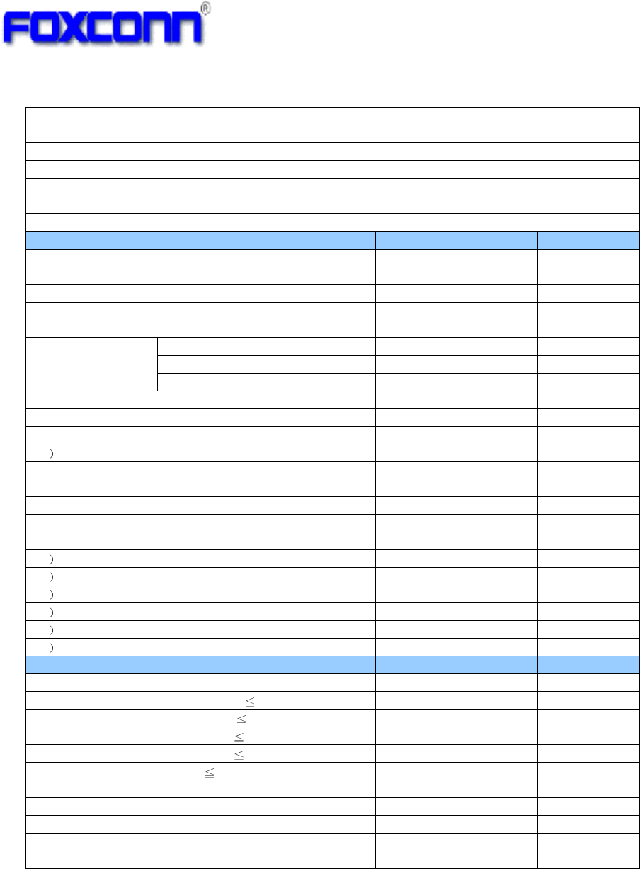
3.2.3 802.11n HT20 Mode
Items
Contents
Standard
IEEE802.11n
HT20
@ 2.4GHz
Modulation type
MIMO
-
OFDM
Channel CH1 to CH13
Data rate (MCS index) MCS0/1/2/3/4/5/6/7
TX Characteristics
(per chain)
Min.
Typ.
Max.
Unit
1
. Transmitter Output Power
1) 11n HT20 Target Power
13 15 17
dBm
2
. Spectrum Mask @
target power
1) at fc +/- 11MHz -20 dBr
2) at fc +/- 20MHz -28 dBr
3) at fc > +/-30MHz
-
45
dBr
3. Constellation Error(EVM)@ target power
1) MCS0
-5
dB
2) MCS1
-10
dB
3) MCS2 -13 dB
4) MCS3 -16 dB
5) MCS4
-19
dB
6) MCS5
-22
dB
7) MCS6
-25
d
B
8) MCS7
-
32
-28
dB
4. Frequency Error -25 -1.2 +25 ppm
RX Characteristics
(per chain)
Min. Typ. Max.
Unit
5
. Minimum Input Level Sensitivity
1) MCS0 (PER
10%)
-
91.0
-82
dBm
2) MCS1 (PER
10%)
-
88.3
-79
dBm
3) MCS2 (PER
10%)
-
85.9
-77
dBm
4) MCS3 (PER 10%) -83.5
-74 dBm
5) MCS4 (PER 10%) -80.2
-70 dBm
6) MCS5 (PER
10%)
-
75.5
-66
dBm
7) MCS6 (PER
10%)
-
74.1
-65
dBm
8) MCS7 (PER
10%)
-71.9
-64
dBm
6
. Maximum Input Level (PER
10%)
-20
dBm
COMPANY CONFIDENTIAL
12
3.2.4 802.11n HT40 Mode
3.3 On-board Antenna Specification
Operating Frequency 2.412~2.472GHz
VSWR(ANT1and ANT2) <=2.0:1
Isolation(ANT1& ANT2) >=15dB
Antenna Type Metal ANT
Items
Contents
S
tandard
IEEE802.11n
HT
4
0
@ 2.4GHz
Modulation type
MIMO
-
OFDM
Channel CH3 to CH11
Data rate (MCS index) MCS0/1/2/3/4/5/6/7
TX Characteristics
(per chain)
Min.
Typ.
Max.
Unit
1
. Transmitter Output Power
1) 11n HT40 Target power
12 14 16
dBm
2
. Spectrum Mask @
target power
1) at fc +/- 22MHz -20 dBr
2) at fc +/- 40MHz -28 dBr
3) at fc > +/-60MHz
-
45
dBr
3. Constellation Error(EVM)@target power
1) MCS0
-5
dB
2) MCS1
-10
dB
3) MCS2 -13 dB
4) MCS3 -16 dB
5) MCS4
-19
dB
6) MCS5
-22
dB
7) MCS6
-25
dB
8) MCS7
-
32
-28
dB
4. Frequency Error -25 -1.1
+25 ppm
RX Characteristics
(per chain)
Min. Typ.
Max.
Unit
5
. Minimum Input Level Sensitivity
1) MCS0 (PER
10%)
-
87.2
-79
dBm
2) MCS1 (PER
10%)
-
84.1
-76
dBm
3) MCS2 (PER
10%)
-
81.3
-74
dBm
4) MCS3 (PER 10%) -79.7
-71 dBm
5) MCS4 (PER 10%) -74.5
-67 dBm
6) MCS5 (PER
10%)
-
73.0
-63
dBm
7) MCS6 (PER
10%)
71.2
-62
dBm
8) MCS7 (PER
10%)
-68.8
-61
dBm
6
. Maximum Input Level (PER
10%)
-20
dBm
COMPANY CONFIDENTIAL
13
3.3 BT RF Specification
4. Compatibility and Certification Information
The 8797 combo module shall pass the standard test plan, which includes hardware
compatibility and reliability, and software compatibility test.
5. Quality
The product quality must be followed-up by Foxconn factory quality control system.
Items
Contents
Standard BTv4.0
Modulation technology HFSS
Modulation type
GFSK, π/4
-
DQPSK, 8DPSK
Frequency range
240
2
MHz ~ 2480MHz
Numbers of Channel
79 channels with 1MHz
Bandwid
th
Data rate (MCS index) 1Mbps/2Mbps/3Mbps
TX Characteristics
Min. Typ.
Max.
Unit
1. BDR
Transmitter Output Power
1) Target power (class2)
-6 2.0 +4
dBm
2. BDR Initial Carrier Freq. Tolerance
-
75
-
1.3
+75
KHz
3. BDR Carrier Drift
1)
Drift Rate/50us
-
20
4.7
+20
KHz
2) Average
Drift
-25 -1 +25 dB dB
-40 +2 +40 KHz KHz
-
40
0
+40
KHz
KHz
4. BDR Modulation Characteristic
1) F1avg(kHz)
140
162.1
175
KHz
2) F2avg(kHz)
115
146.5
-
KHz
3 F1/F2 Ratio 0.8 0.9 - -
5 EDR Carrier Frequency Stability and
Modulation Accuracy
1) Initial Frequency Error
-
75
-
1.3
+75
KHz
2) Frequency Error
-
10
0.6
+10
KHz
3) Block Frequency Error
-
75
-
1.2
+75
KHz
4 RMS DEVM @2Mbps
0.2
0.045
-
5 Peak DEVM @2Mbps 0.35 0.1 -
6
99% DEVM
@
% Symbols <= 0.3 (2Mbps) 99% 100%
-
7 RMS DEVM @3Mbps
0.13
0.037
-
8 Peak DEVM @3Mbps
0.25
0.08
-
9
99% DEVM
@
% Symbols <= 0.2(3Mbps)
99%
100%
-
RX Characteristics
Unit
6. Minimum Input Level Sensitivity
1) BDR Single slot sensitivity (BER 0.1%) -70 dBm
2)
BDR Multi slot
sensitivity
(
B
ER
0.1
%)
-70
dBm
3)
EDR
sensitivity
@2Mbps
(
B
ER
0.
0
1
%)
-70
dBm
4)
EDR
sensitivity
@
3
Mbps
(
B
ER
0.
0
1
%)
-70
dBm
7
. Maximum Input Level (
B
ER
0.1
%)
-20
dBm
COMPANY CONFIDENTIAL
14
6. Appendix
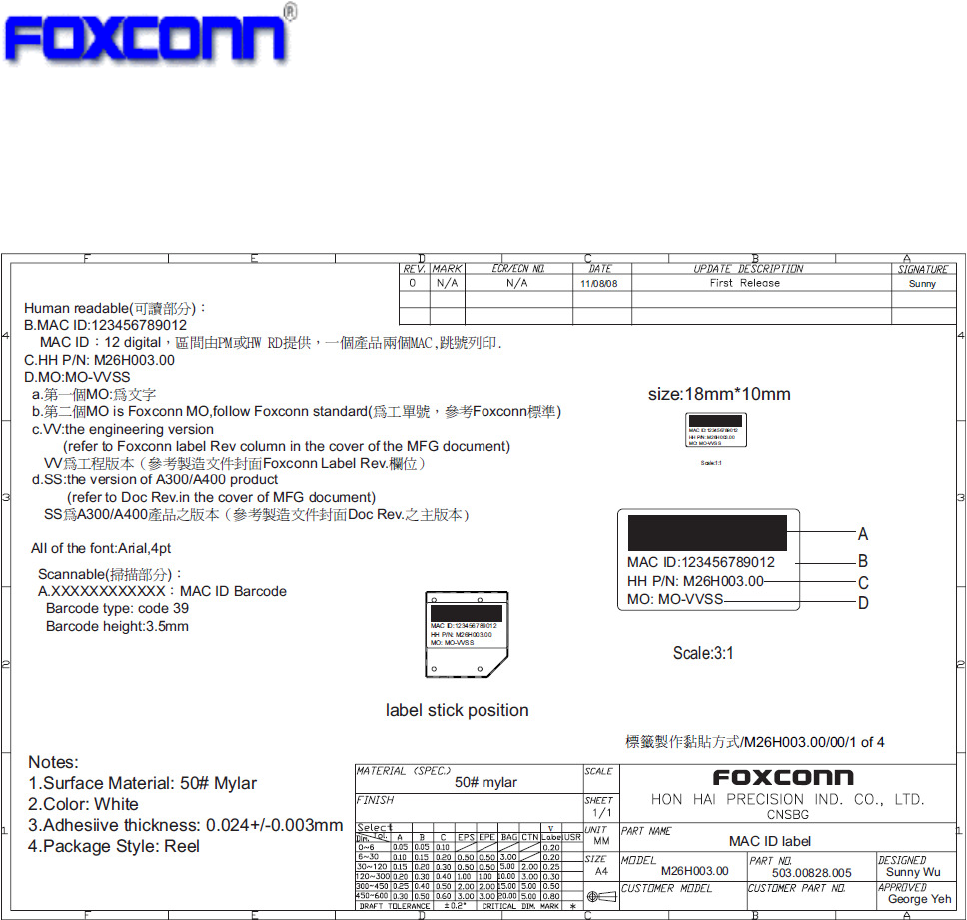
Appendix A - Label Information
COMPANY CONFIDENTIAL
15
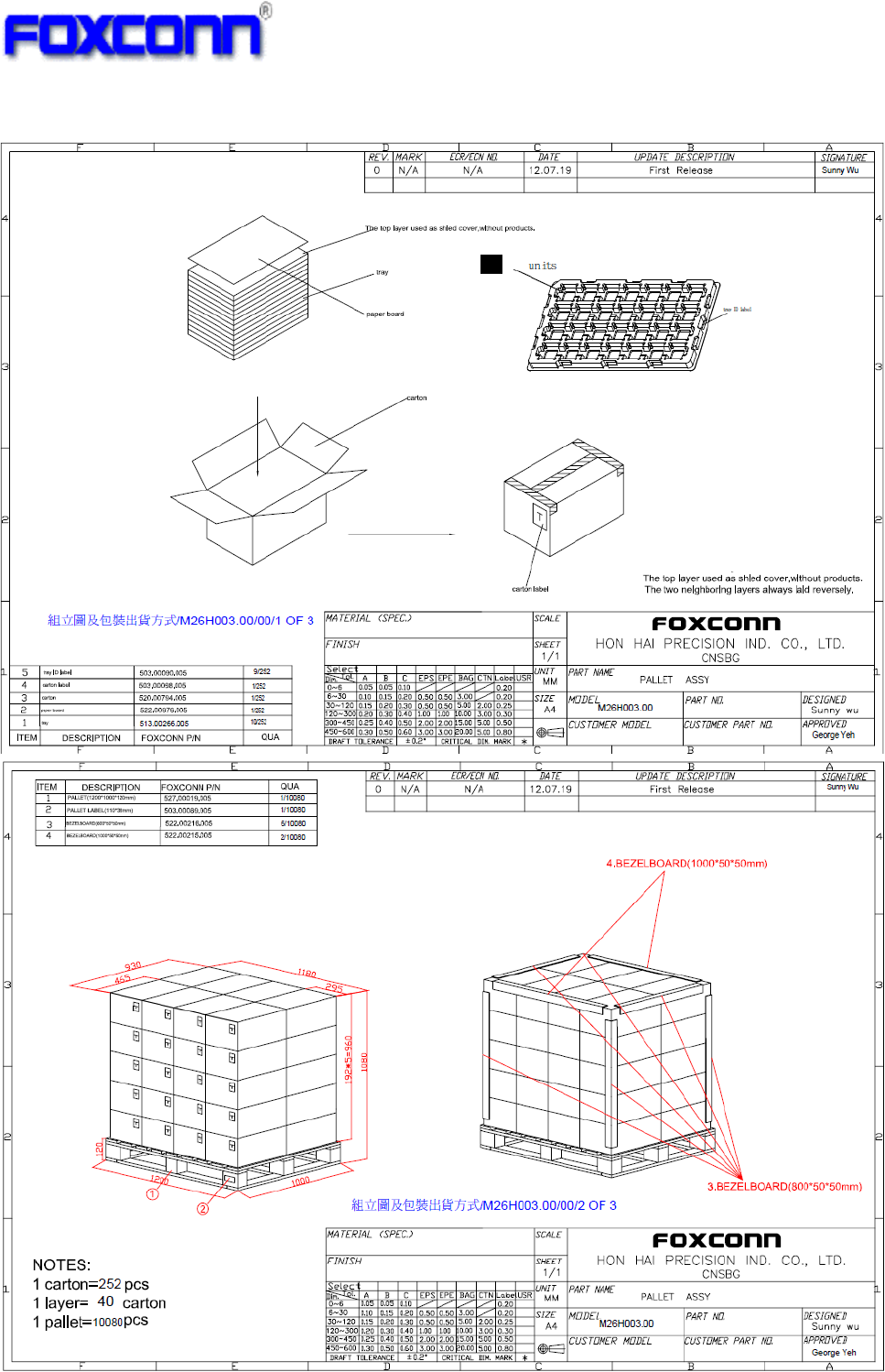
Appendix B - Package Information

COMPANY CONFIDENTIAL
Federal Communication Commission Interference Statement
This equipment has been tested and found to comply with the limits for a Class B digital device, pursuant to
Part 15 of the FCC Rules. These limits are designed to provide reasonable protection against harmful
interference in a residential installation. This equipment generates, uses and can radiate radio frequency
energy and, if not installed and used in accordance with the instructions, may cause harmful interference to
radio communications. However, there is no guarantee that interference will not occur in a particular
installation. If this equipment does cause harmful interference to radio or television reception, which can be
determined by turning the equipment off and on, the user is encouraged to try to correct the interference by
one of the following measures:
- Reorient or relocate the receiving antenna.
- Increase the separation between the equipment and receiver.
- Connect the equipment into an outlet on a circuit different from that to which the receiver is connected.
- Consult the dealer or an experienced radio/TV technician for help.
FCC Caution:
Any changes or modifications not expressly approved by the party responsible for compliance could void the
user's authority to operate this equipment.
This device complies with Part 15 of the FCC Rules. Operation is subject to the following two conditions:
(1) This device may not cause harmful interference, and
(2) This device must accept any interference received, including interference that may cause undesired
operation.
FCC Radiation Exposure Statement:
This equipment complies with FCC radiation exposure limits set forth for an uncontrolled environment. This
transmitter module must not be co-located or operating in conjunction with any other antenna or
transmitter.
This End equipment should be installed and operated with a minimum distance of 20 centimeters between the
radiator and your body.
IMPORTANT NOTE:
In the event that these conditions can not be met (for example certain laptop configurations or co-location
with another transmitter), then the FCC authorization is no longer considered valid and the FCC ID can not
be used on the final product. In these circumstances, the OEM integrator will be responsible for re-evaluating
the end product (including the transmitter) and obtaining a separate FCC authorization.
End Product Labeling
The final end product must be labeled in a visible area with the following:
“Contains FCC ID: N89-NU260HS”.
Manual Information to the End User
The OEM integrator has to be aware not to provide information to the end user regarding how to install or
remove this RF module in the user’s manual of the end product which integrates this module.