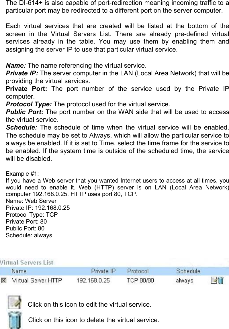
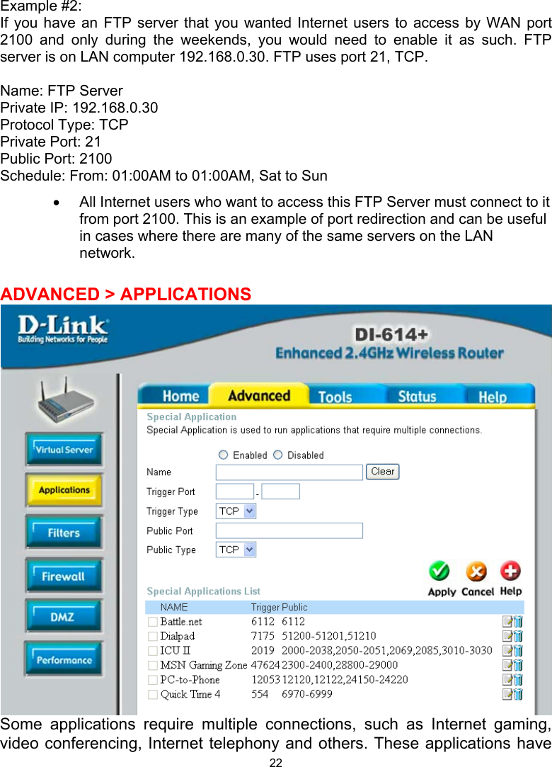
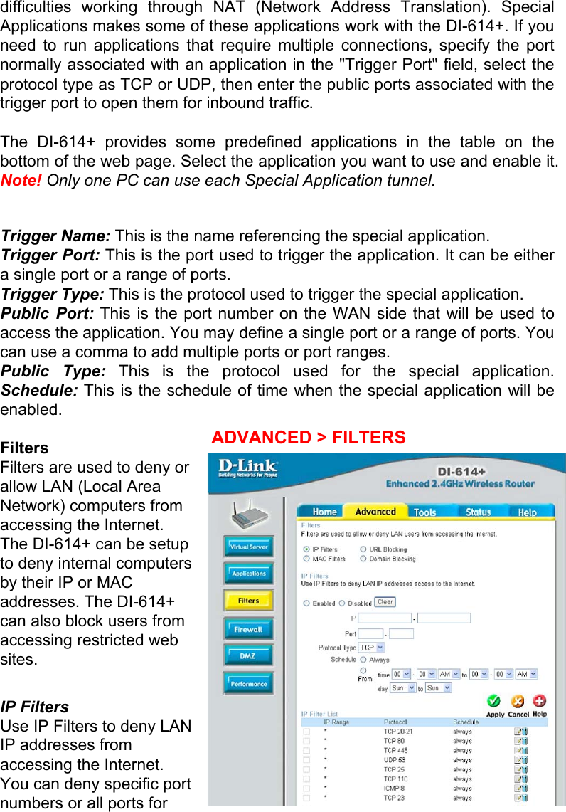
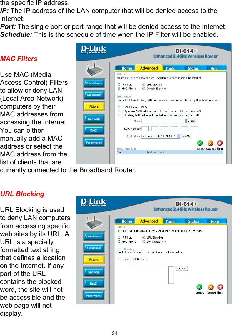
D Link D1614-PLUS Wireless Broadband Router User Manual di614 manual 202 070502
D Link Corporation Wireless Broadband Router di614 manual 202 070502
UserManual.wiki
>
D Link
>
D1614-PLUS User Manual
>
Manual Part 1
Contents
1.
Manual Part 1
2.
Manual Part 2
3.
Manual Part 3
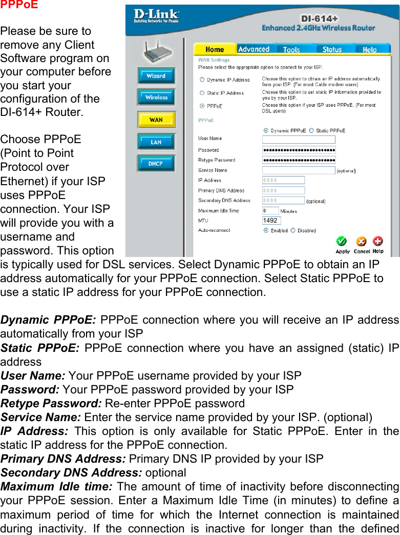
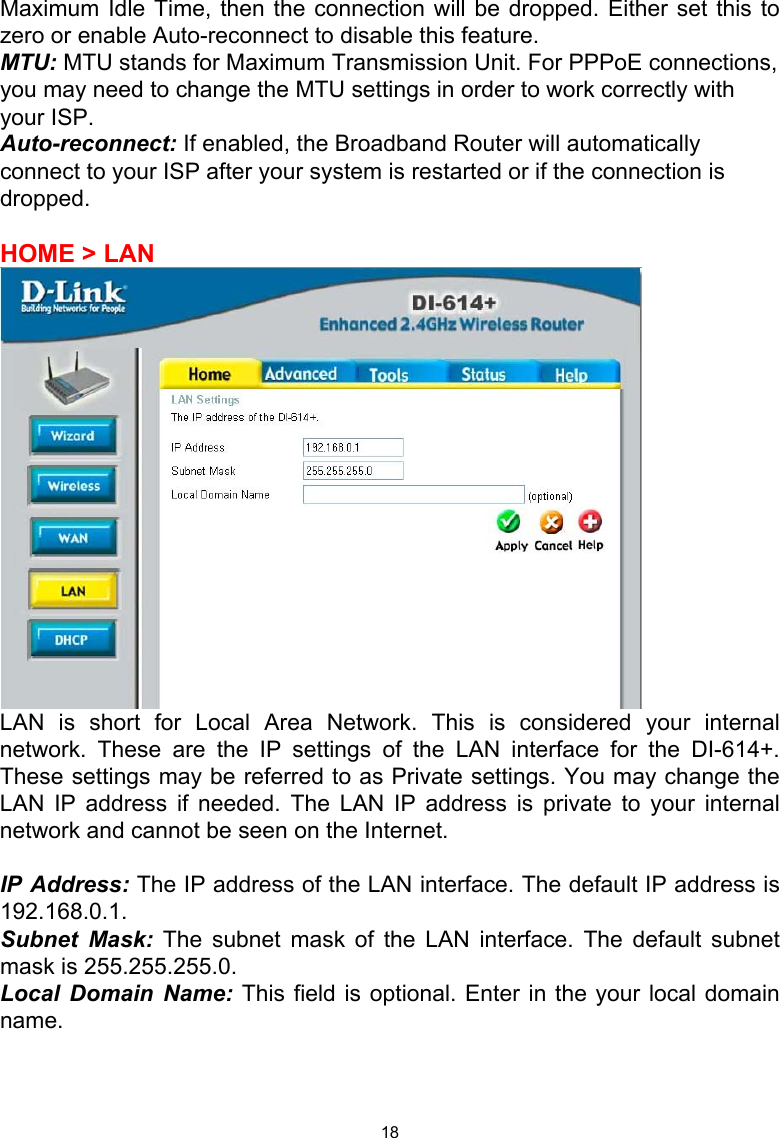
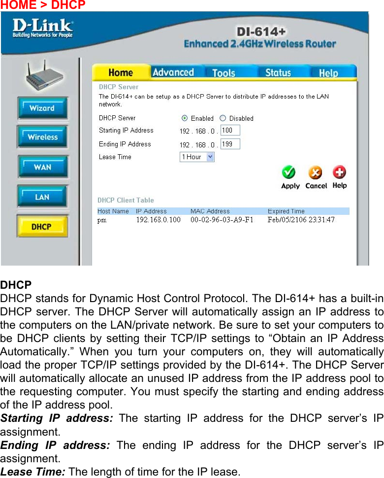
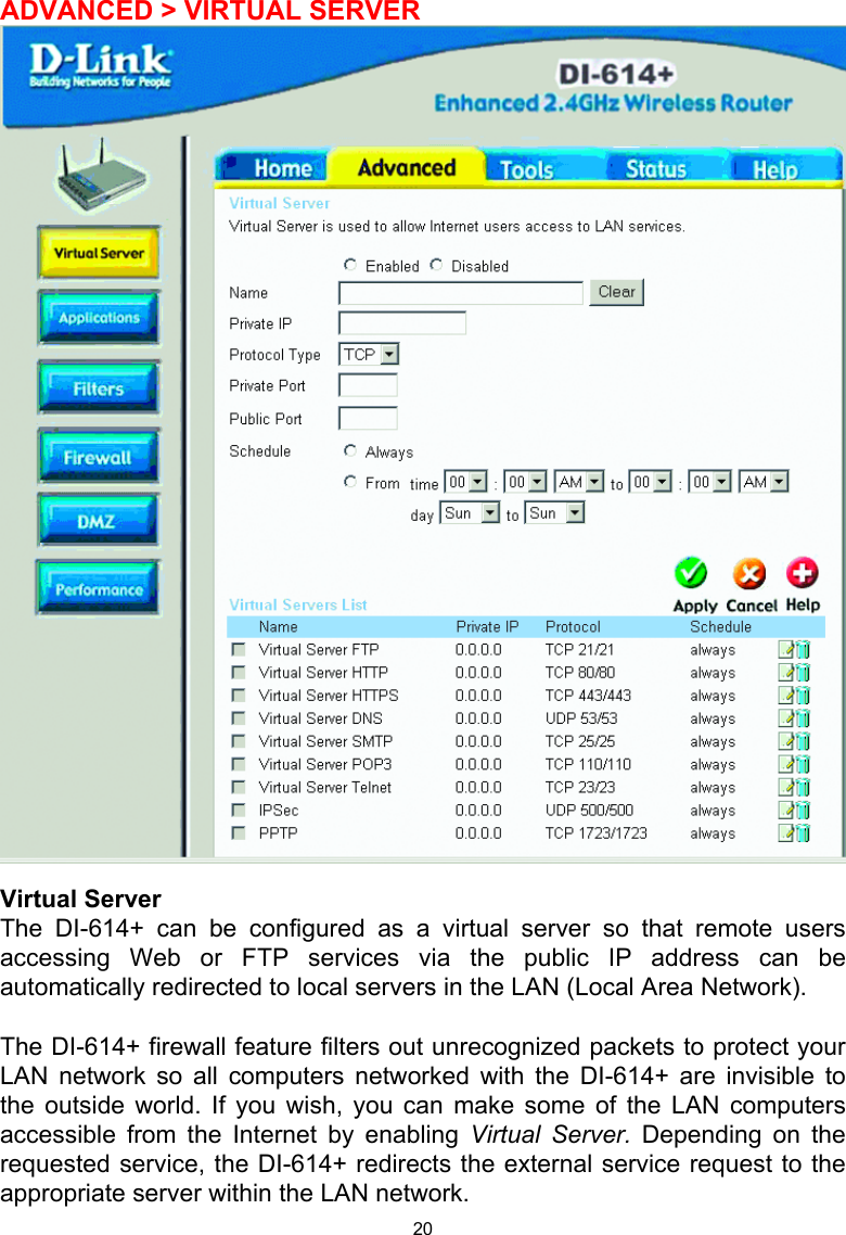
Manual Part 1
Navigation menu
Upload a User Manual
Namespaces
Wiki Guide
HTML
PDF
Info
Views
User Manual
Discussion / Help
Navigation