D Link D1614-PLUS Wireless Broadband Router User Manual di614 manual 202 070502
D Link Corporation Wireless Broadband Router di614 manual 202 070502
D Link >
Contents
- 1. Manual Part 1
- 2. Manual Part 2
- 3. Manual Part 3
Manual Part 1

AirPlus DI-614+
Enhanced 2.4 GHz Wireless Broadband Router
Manual
Rev. 070502
Building Networks for People
2
Contents
1. Package Contents ............................................. 3
2. Introduction........................................................ 4
3. Wireless Basics ................................................. 7
4. Getting Started ................................................ 10
5. Using the Configuration Menu......................... 12
6. Troubleshooting............................................... 33
7. Networking Basics........................................... 38
8. Technical Specifications .................................. 70
9. Contacting Technical Support.......................... 72
10. Warranty and Registration ............................... 73
1. Package Contents
Contents of Package:
• D-Link AirPlus DI-614+ Enhanced 2.4GHz Wireless Access Point
• Power Adapter – 5V DC, 2.5A
• Manual on CD
• Quick Installation Guide
Note: Using a power supply with a different voltage rating than the one included with
the DI-614+ will cause damage and void the warranty for this product.
If any of the above items are missing, please contact your reseller.
System Requirements:
• Computer with a Windows, Macintosh, or Linux based operating
system with an installed Ethernet adapter
• Internet Explorer or Netscape Navigator, version 4.0 or above, with
JavaScript enabled
4
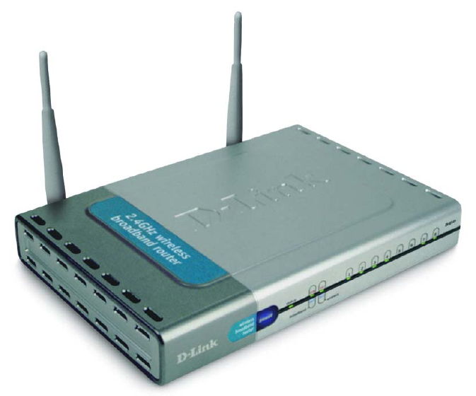
2. Introduction
The D-Link AirPlus DI-614+ Wireless Broadband Router is an enhanced
802.11b high-performance, wireless router. It is an ideal way to extend the
reach and number of computers connected to your wireless network.
Unlike most 802.11b routers, the DI-614+ is capable of data transfer speeds
up to 22 Mbps (compared to the standard 11 Mbps) when used with other D-
Link AirPlus products such as the DWL-520+ Wireless PCI Adapter.
After completing the steps outlined in the Quick Installation Guide (included
in your package) you will have the ability to share information and resources,
such as files and printers, and enjoy the freedom that wireless networking
delivers.
The DI-614+ is compatible with most popular operating systems, including
Macintosh, Linux and Windows, and can be integrated into a large network.
This Manual is designed to help you connect the Router and the D-Link
AirPlus 2.4GHz Wireless Adapters into a network in Infrastructure mode.
Please take a look at the Getting Started section in this manual to see an
example of an Infrastructure network using the DI-614+.
This manual provides a quick introduction to wireless technology and its
application as it relates to networking. Please take a moment to read
through this manual and get acquainted with wireless technology.
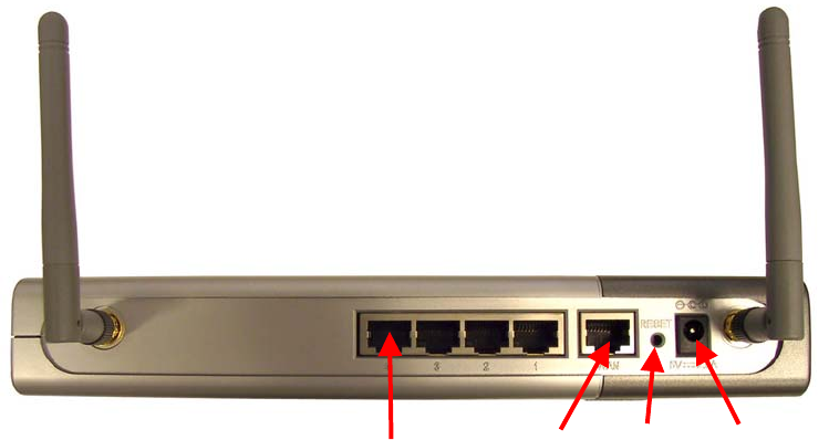
Connections
Ports 1-4 WAN Reset Power
Reset: Used to restore the DI-614+ to the factory default settings
Power: Connect one end of the included power adapter into the power port
and the other end into the power outlet.
WAN: WAN port socket (CAT5 Ethernet RJ-45 cable.) Connect your Cable
or DSL modem.
PORTS 1-4: LAN port sockets (CAT5 Ethernet RJ-45 cable.) The LED
glows steadily when a port is connected to a hub, switch or network-adapter-
equipped computer in the local area network.
Features and Benefits
• Connects multiple computers to a Broadband (Cable or DSL) modem
to share the Internet connection
• Supports VPN pass-through, providing added security
• Advanced Firewall features
• DHCP server supported enables all networked computers to
automatically receive IP addresses
• Up to 2x faster with other AirPlus products with speeds up to 22Mbps
• Web-based interface for Managing and Configuring
• Access Control to manage users on the network
• Supports special applications that require multiple connections
• Operates in the 2.4GHz frequency range
• Maximum reliability, throughput and connectivity with automatic data
rate switching.
• Stronger network security with 256-bit encryption.
6
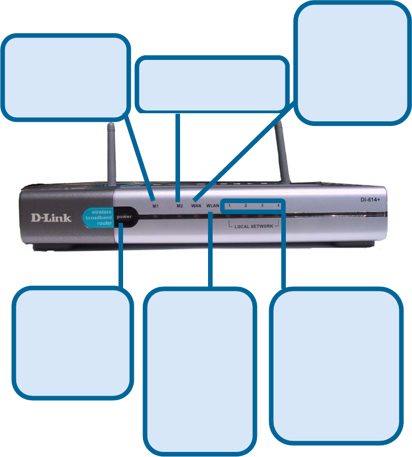
LEDS
M2 LED -
A solid light indicates that
the unit is defective.
M1 LED -
A solid light
indicates that the
DI-614+ is ready.
WAN LED -
A solid light
indicates
connection on the
WAN port. This
LED blinks during
data transmission.
POWER LED -
A solid light
indicates a proper
connection to the
power supply.
WLAN LED -
A solid light
indicates that the
wireless segment
is ready. This
LED blinks
during wireless
data
transmission.
LOCAL
NETWORK LED -
A solid light
indicates a
connection to an
Ethernet-enabled
computer on ports
1-4. This LED
blinks during data
transmission.
3. Wireless Basics
D-Link AirPlus wireless products are based on industry standards to provide
easy-to-use and compatible high-speed wireless connectivity within your
home, business or public access wireless networks. Strictly adhering to the
IEEE standard, the D-Link AirPlus wireless family of products will allow you
to access the data you want, when and where you want it. You will be able to
enjoy the freedom that wireless networking delivers.
A wireless local area network (WLAN) is a cellular computer network that
transmits and receives data with radio signals instead of wires. Wireless
LANs are used increasingly in both home and office environments, and
public areas such as airports, coffee shops and universities. Innovative ways
to utilize WLAN technology are helping people to work and communicate
more efficiently. Increased mobility and the absence of cabling and other
fixed infrastructure have proven to be beneficial for many users.
Wireless users can use the same applications they use on a wired network.
Wireless adapter cards used on laptop and desktop systems, support the
same protocols as Ethernet adapter cards.
Under many circumstances, it may be desirable for mobile network devices
to link to a conventional Ethernet LAN in order to use servers, printers or an
Internet connection supplied through the wired LAN. A Wireless Access
Point (AP) is a device used to provide this link.
People use wireless LAN technology for many different purposes:
Mobility - Productivity increases when people have access to data in any
location within the operating range of the WLAN. Management decisions
based on real-time information can significantly improve worker efficiency.
Low Implementation Costs – WLANs (Wireless Local Area Networks) are
easy to set up, manage, change and relocate. Networks that frequently
change, both physically and logically, can benefit from WLANs ease of
implementation. WLANs can operate in locations where installation of wiring
may be impractical.
Installation Speed and Simplicity - Installing a wireless LAN system can
be fast and easy and can eliminate the need to pull cable through walls and
ceilings.
8
Wireless Basics
Network Expansion - Wireless technology allows the network to go where
wires cannot go.
Reduced Cost-of-Ownership - While the initial investment required for
wireless LAN hardware might be higher than the cost of wired LAN hardware,
overall installation expenses and life-cycle costs will be significantly lower.
Long-term cost benefits are greatest in dynamic environments requiring
frequent moves, adds, and changes.
Scalability – Wireless Local Area Networks (WLANs) can be configured in a
variety of topologies to meet the needs of specific applications and
installations. Configurations are easily changed and range from peer-to-peer
networks suitable for a small number of users to full infrastructure networks
of thousands of users that allow roaming over a broad area.
D-Link AirPlus Wireless Family of LAN products include:
Enhanced 2.4GHz Wireless Cardbus Adapters used with laptop
computers (DWL-650+)
Enhanced 2.4GHz Wireless PCI cards used with desktop computers
(DWL-520+)
Enhanced 2.4GHz Wireless Router and Access Point (DI-614+,DWL-
900AP+)
The DI-614+ is also compatible with the D-Link Air 802.11b family of
products, which include:
2.4GHz Wireless Cardbus Adapters used with laptop computers
(DWL-650)
2.4GHz Wireless PCI cards used with desktop computers (DWL-520)
Wireless Router/Access Point/Print Servers (DI-713P)
Wireless Access Points (DWL-1000AP, DWL-900AP)
Standards - Based Technology
The IEEE standard-based technology assures that the D-Link AirPlus
Products are interoperable with existing compatible 2.4GHz wireless
technology. This means you will be able to transfer large files quickly or
even watch a movie in MPEG format over your network without noticeable
delays. The technology works by using multiple frequencies in the 2.4GHz
range at speeds up to 22 Mbps. D-Link AirPlus products will automatically
Wireless Basics
sense the best possible connection speed to ensure the greatest speed and
range possible with the technology.
Installation Considerations
Designed to go up to 1,312 feet (400 meters) outdoors and up to 328 feet
(100 meters) indoors, D-Link AirPlus DI-614+ lets you access your network
with your laptop computer from virtually anywhere. Keep in mind, however,
that the number, thickness and location of walls, ceilings or other objects that
the wireless signals must pass thru may limit range. Typical ranges vary
depending on the types of materials and background RF (radio frequency)
noise in your home or business. The key to maximizing range is to follow
these basic guidelines:
1. Keep the number of walls and ceilings between the wireless Access
Point and your receiving device (e.g., the DWL-650+) to a minimum -
Each wall or ceiling can reduce your D-Link Air Wireless product’s range
from 3-90 feet (1-30 meters.) Position your Access Points, Residential
Gateways, and computers so that the number of walls or ceilings is
minimized.
2. Be aware of the direct line between Access Points, Residential
Gateways (routers) and computers. A wall that is 1.5 feet thick (.5
meters), at a 45-degree angle appears to be almost 3 feet (1 meter) thick.
At a 2-degree angle it looks over 42 feet (14 meters) thick! Try to make
sure that the Access Points and adapters are positioned so that the
signal will travel straight through a wall or ceiling for better reception.
3. Building Materials make a difference - A solid metal door or aluminum
studs may have a negative effect on range. Try to position Access Points,
and computers with wireless adapters so that the signal passes through
drywall or open doorways and not other materials.
4. Make sure that the device’s antenna is positioned for best reception by
using the software signal strength tools included with your product.
5. Keep your product away (at least 3-6 feet or 1-2 meters) from electrical
devices or appliances that may generate extreme RF noise.
For the average home, signal range should not be an issue. If you
experience low or no signal strength in areas of your home that you wish to
access, consider positioning the Access Point in a location directly between
the computers with wireless adapters. Additional Access Points can be
connected to provide better coverage in rooms where the signal does not
appear as strong as desired.

10
4. Getting Started
For the price of a single IP Address from your Broadband Internet Service
provider you can share the Internet with all the computers on your local
network, without sacrificing speed or security, using D-Link AirPlus
networking products.
IP ADDRESS
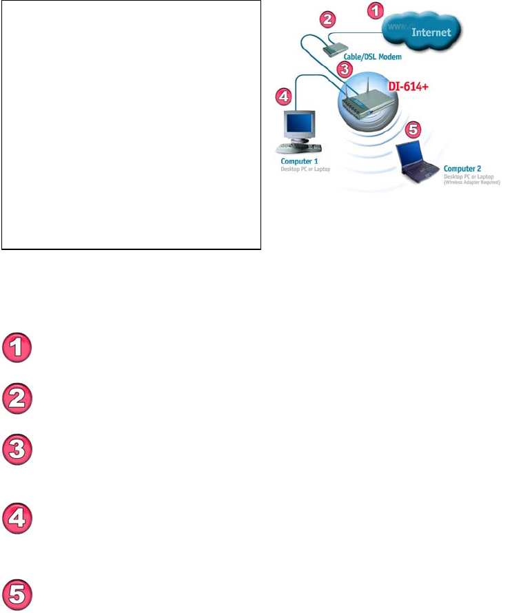
The Infrastructure Network example shown on the following page contains
the following D-Link network devices:
A wireless Broadband Router - D-Link AirPlus DI-614+
A laptop computer with a wireless adapter - D-Link AirPlus DWL-650+
A desktop computer with a wireless adapter - D-Link AirPlus DWL-520+
A Cable modem - D-Link DCM-200
DHCP stands for Dynamic Host Configuration Protocol.
It is a protocol for assigning dynamic IP addresses “automatically.”
With a DHCP-capable gateway/router, there is
no need to manually assign an IP address.
Please note: If you have a DHCP-capable router, such as the
D-Link DI-614+, there is no need to assign an IP Address.
If you need to assign IP Addresses to the computers on the
network, please remember that the IP Address for each
computer must be in the same IP Address range as all the
computers in the network, and the Subnet mask must be exactly
the same for all the computers in the network.
For example: If the first computer is assigned an IP Address o
f
192.168.0.2 with a Subnet Mask of 255.255.255.0, then the second
computer can be assigned an IP Address of 192.168.0.3 with a
Subnet Mask of 255.255.255.0, etc.
IMPORTANT: If computers or other devices are assigned the
same IP Address, one or more of the devices may not be
visible on the network.
Right out of the box, with its default settings, the DI-614+ will
automatically connect with other D-Link Air or AirPlus products.
Getting Started
Setting Up an Infrastructure Network
Please remember that D-Link AirPlus wireless devices are pre-configured to
connect together, right out of the box, with the default settings.
You will need a broadband Internet access (Cable/DSL)
subscription.
Consult with your Cable/DSL provider for proper installation of the
modem.
Connect the modem to the DI-614+ Wireless Broadband Router.
See the Quick Installation Guide included with the router.
If you are including a desktop computer in your network, you can
install the D-Link DFE-530TX+ Ethernet NIC adapter into the
desktop computer. See the Quick Installation Guide included with the
DFE-530TX+.
Please refer to the following sections
of this manual for additional
information about setting up a network:
Networking Basics- learn how to
check your IP Address; share printers
and files.
Using the Configuration Utility- learn
the settings you must use on each
computer in your network for
successful communication.
Troubleshooting- learn how to chec
k
for the proper installation of the
network adapters’ drivers and othe
r
tips for troubleshooting the network.
Install the drivers for the wireless network adapter (such as the
D-Link AirPlus DWL-650+) into the laptop computer. See the
Quick Installation Guide included with the DWL-650+.
12
5. Using the Configuration Menu
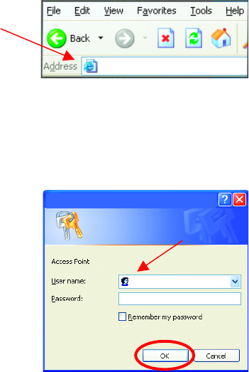
Whenever you want to configure your network or the DI-614+, you can
access the Configuration Utility by opening the web-browser and typing in
the IP Address of the DI-614+. The DI-614+ default IP Address is shown
below:
(The IP Address shown in the example above is the default setting. If you have changed the
IP Address of the DI-614+ to conform to a network, then input that IP Address in the web
browser, instead of the default IP Address shown.)
Setup Wizard
The Setup Wizard page is the first page that appears when logging into the
web-based management interface. The Setup Wizard is a utility used to
quickly configure the DI-614+. It will guide you through four quick and basic
steps to help you connect to your ISP. You will be connected to your ISP
(Internet Service Provider) and have Internet access within minutes.
• Open the web browser
• Type in the IP Address of
the Access Point
• Type admin in the
User Name field
(lower case)
• Leave the
Password blank
• Click OK
http://192.168.0.1
admin
Connect to 192.168.0.1
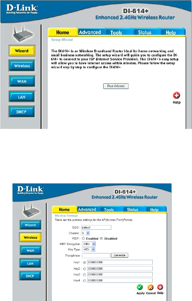
Home > Wizard
Wireless
Wireless Settings are settings for the (Access Point) Portion of the Wireless
Router. Allow you to change the wireless settings to fit an existing wireless
network or to customize your wireless network.
Home > Wireless
14
SSID
Service Set Identifier (SSID) is the name designated for a specific wireless
local area network (WLAN). The SSID’s factory default setting is “default”.
The SSID can be easily changed to connect to an existing wireless network
or to establish a new wireless network.
Channel
Indicates the channel setting for the DI-614+. By default the channel is set to
6. The Channel can be changed to fit the channel setting for an existing
wireless network or to customize the wireless network.
WEP
Wired Equivalent Protocol (WEP) is a wireless security protocol for Wireless
Local Area Networks (WLAN). WEP provides security by encrypting the
data that is sent over the WLAN. The DI-614+ supports 3 levels of WEP
Encryption: 64Bit encryption, 128Bit encryption, and 256Bit encryption. WEP
is disabled by default. The WEP setting can be changed to fit an existing
wireless network or to customize your wireless network.
Key Type
The Key Types that are supported by the DI-614+ are HEX (Hexadecimal)
and ASCII (American Standard Code for Information Interchange.) The Key
Type can be changed to fit an existing wireless network or to customize your
wireless network.
Passphrase
Enter a passphrase (HEX or ASCII characters) and the DI-614+ will
automatically generate the keys 1-4 when the “Generate” button is pressed.
KEYS
Keys 1-4 allow you to easily change wireless encryption settings to maintain
a secure network. Simply select the specific key to be used for encrypting
wireless data on the network.
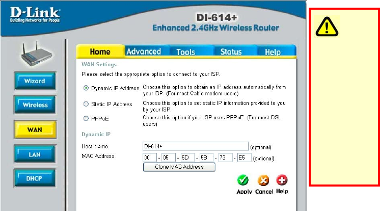
WAN
WAN is short for Wide Area Network. The WAN settings can be referred to
as the Public settings. All IP information in the WAN settings are public IP
addresses which are accessible on the Internet.
The WAN settings consist of three options: Dynamic IP Address, Static IP
Address, and PPPoE. Select the appropriate option and fill in the
information needed to connect to your ISP.
Home > WAN
Dynamic IP Address
Choose Dynamic IP Address to obtain IP address information automatically
from your ISP. Select this option if your ISP does not give you any IP
numbers to use. This option is commonly used for Cable modem services.
Host Name: The Host Name field is optional but may be required by some
ISPs. The host name is the device name of the Broadband Router.
MAC Address: The default MAC address is set to the WAN's physical
interface MAC address on the Broadband Router. You can use the "Clone
MAC Address" button to copy the MAC address of the Ethernet Card
installed by your ISP and replace the WAN MAC address with this MAC
address. It is not recommended that you change the default MAC address
unless required by your ISP.
Please be
sure to
remove
any
existing
PPPoE
client
software
installed
on your
computers
16
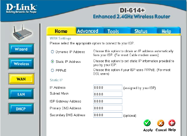
Static IP Address
Choose Static IP Address if all WAN IP information is provided to you by
your ISP. You will need to enter in the IP address, subnet mask, gateway
address, and DNS address(es) provided to you by your ISP. Each IP
address entered in the fields must be in the appropriate IP form, which are
four IP octets separated by a dot (x.x.x.x). The Router will not accept the IP
address if it is not in this format.
IP Address: Public IP address provided by your ISP.
Subnet Mask: Subnet mask provided by your ISP.
ISP Gateway Address: Public IP address of your ISP that you are
connecting to.
Primary DNS Address: Primary DNS (Domain Name Server) IP provided
by your ISP
Secondary DNS Address: optional
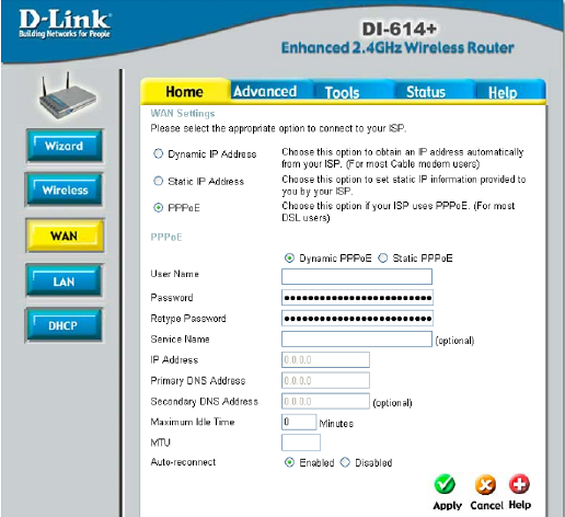
PPPoE
Please be sure to
remove any Client
Software program on
your computer before
you start your
configuration of the
DI-614+ Router.
Choose PPPoE
(Point to Point
Protocol over
Ethernet) if your ISP
uses PPPoE
connection. Your ISP
will provide you with a
username and
password. This option
is typically used for DSL services. Select Dynamic PPPoE to obtain an IP
address automatically for your PPPoE connection. Select Static PPPoE to
use a static IP address for your PPPoE connection.
Dynamic PPPoE: PPPoE connection where you will receive an IP address
automatically from your ISP
Static PPPoE: PPPoE connection where you have an assigned (static) IP
address
User Name: Your PPPoE username provided by your ISP
Password: Your PPPoE password provided by your ISP
Retype Password: Re-enter PPPoE password
Service Name: Enter the service name provided by your ISP. (optional)
IP Address: This option is only available for Static PPPoE. Enter in the
static IP address for the PPPoE connection.
Primary DNS Address: Primary DNS IP provided by your ISP
Secondary DNS Address: optional
Maximum Idle time: The amount of time of inactivity before disconnecting
your PPPoE session. Enter a Maximum Idle Time (in minutes) to define a
maximum period of time for which the Internet connection is maintained
during inactivity. If the connection is inactive for longer than the defined
1492
18
Maximum Idle Time, then the connection will be dropped. Either set this to
zero or enable Auto-reconnect to disable this feature.
MTU: MTU stands for Maximum Transmission Unit. For PPPoE connections,
you may need to change the MTU settings in order to work correctly with
your ISP.
Auto-reconnect: If enabled, the Broadband Router will automatically
connect to your ISP after your system is restarted or if the connection is
dropped.
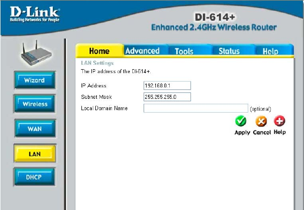
HOME > LAN
LAN is short for Local Area Network. This is considered your internal
network. These are the IP settings of the LAN interface for the DI-614+.
These settings may be referred to as Private settings. You may change the
LAN IP address if needed. The LAN IP address is private to your internal
network and cannot be seen on the Internet.
IP Address: The IP address of the LAN interface. The default IP address is
192.168.0.1.
Subnet Mask: The subnet mask of the LAN interface. The default subnet
mask is 255.255.255.0.
Local Domain Name: This field is optional. Enter in the your local domain
name.
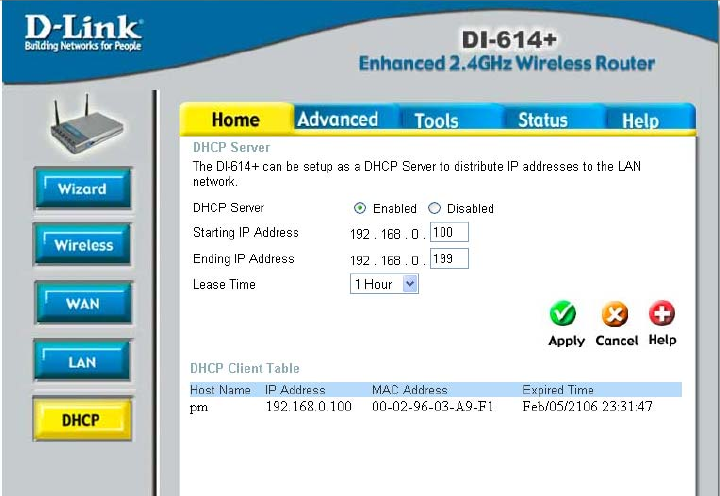
HOME > DHCP
DHCP
DHCP stands for Dynamic Host Control Protocol. The DI-614+ has a built-in
DHCP server. The DHCP Server will automatically assign an IP address to
the computers on the LAN/private network. Be sure to set your computers to
be DHCP clients by setting their TCP/IP settings to “Obtain an IP Address
Automatically.” When you turn your computers on, they will automatically
load the proper TCP/IP settings provided by the DI-614+. The DHCP Server
will automatically allocate an unused IP address from the IP address pool to
the requesting computer. You must specify the starting and ending address
of the IP address pool.
Starting IP address: The starting IP address for the DHCP server’s IP
assignment.
Ending IP address: The ending IP address for the DHCP server’s IP
assignment.
Lease Time: The length of time for the IP lease.
20
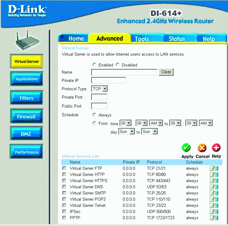
ADVANCED > VIRTUAL SERVER
Virtual Server
The DI-614+ can be configured as a virtual server so that remote users
accessing Web or FTP services via the public IP address can be
automatically redirected to local servers in the LAN (Local Area Network).
The DI-614+ firewall feature filters out unrecognized packets to protect your
LAN network so all computers networked with the DI-614+ are invisible to
the outside world. If you wish, you can make some of the LAN computers
accessible from the Internet by enabling Virtual Server. Depending on the
requested service, the DI-614+ redirects the external service request to the
appropriate server within the LAN network.
The DI-614+ is also capable of port-redirection meaning incoming traffic to a
particular port may be redirected to a different port on the server computer.
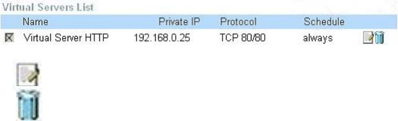
Each virtual services that are created will be listed at the bottom of the
screen in the Virtual Servers List. There are already pre-defined virtual
services already in the table. You may use them by enabling them and
assigning the server IP to use that particular virtual service.
Name: The name referencing the virtual service.
Private IP: The server computer in the LAN (Local Area Network) that will be
providing the virtual services.
Private Port: The port number of the service used by the Private IP
computer.
Protocol Type: The protocol used for the virtual service.
Public Port: The port number on the WAN side that will be used to access
the virtual service.
Schedule: The schedule of time when the virtual service will be enabled.
The schedule may be set to Always, which will allow the particular service to
always be enabled. If it is set to Time, select the time frame for the service to
be enabled. If the system time is outside of the scheduled time, the service
will be disabled.
Example #1:
If you have a Web server that you wanted Internet users to access at all times, you
would need to enable it. Web (HTTP) server is on LAN (Local Area Network)
computer 192.168.0.25. HTTP uses port 80, TCP.
Name: Web Server
Private IP: 192.168.0.25
Protocol Type: TCP
Private Port: 80
Public Port: 80
Schedule: always
Click on this icon to edit the virtual service.
Click on this icon to delete the virtual service.
22
Example #2:
If you have an FTP server that you wanted Internet users to access by WAN port
2100 and only during the weekends, you would need to enable it as such. FTP
server is on LAN computer 192.168.0.30. FTP uses port 21, TCP.
Name: FTP Server
Private IP: 192.168.0.30
Protocol Type: TCP
Private Port: 21
Public Port: 2100
Schedule: From: 01:00AM to 01:00AM, Sat to Sun
• All Internet users who want to access this FTP Server must connect to it
from port 2100. This is an example of port redirection and can be useful
in cases where there are many of the same servers on the LAN
network.
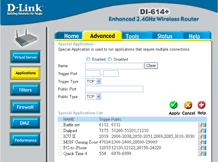
ADVANCED > APPLICATIONS
Some applications require multiple connections, such as Internet gaming,
video conferencing, Internet telephony and others. These applications have
difficulties working through NAT (Network Address Translation). Special
Applications makes some of these applications work with the DI-614+. If you
need to run applications that require multiple connections, specify the port
normally associated with an application in the "Trigger Port" field, select the
protocol type as TCP or UDP, then enter the public ports associated with the
trigger port to open them for inbound traffic.
The DI-614+ provides some predefined applications in the table on the
bottom of the web page. Select the application you want to use and enable it.
Note! Only one PC can use each Special Application tunnel.
Trigger Name: This is the name referencing the special application.
Trigger Port: This is the port used to trigger the application. It can be either
a single port or a range of ports.
Trigger Type: This is the protocol used to trigger the special application.
Public Port: This is the port number on the WAN side that will be used to
access the application. You may define a single port or a range of ports. You
can use a comma to add multiple ports or port ranges.
Public Type: This is the protocol used for the special application.
Schedule: This is the schedule of time when the special application will be
enabled.
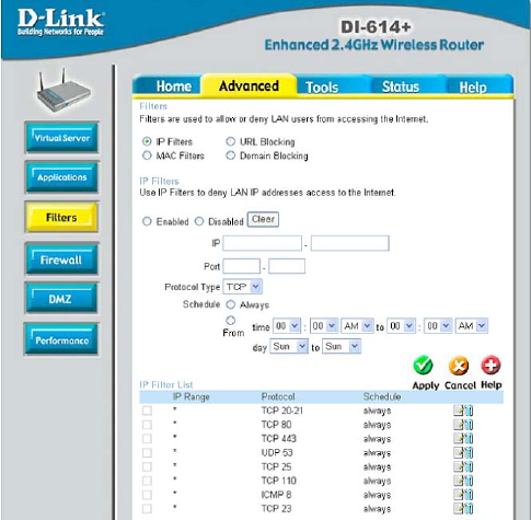
Filters
Filters are used to deny or
allow LAN (Local Area
Network) computers from
accessing the Internet.
The DI-614+ can be setup
to deny internal computers
by their IP or MAC
addresses. The DI-614+
can also block users from
accessing restricted web
sites.
IP Filters
Use IP Filters to deny LAN
IP addresses from
accessing the Internet.
You can deny specific port
numbers or all ports for
ADVANCED > FILTERS
24
the specific IP address.
IP: The IP address of the LAN computer that will be denied access to the
Internet.
Port: The single port or port range that will be denied access to the Internet.
Schedule: This is the schedule of time when the IP Filter will be enabled.
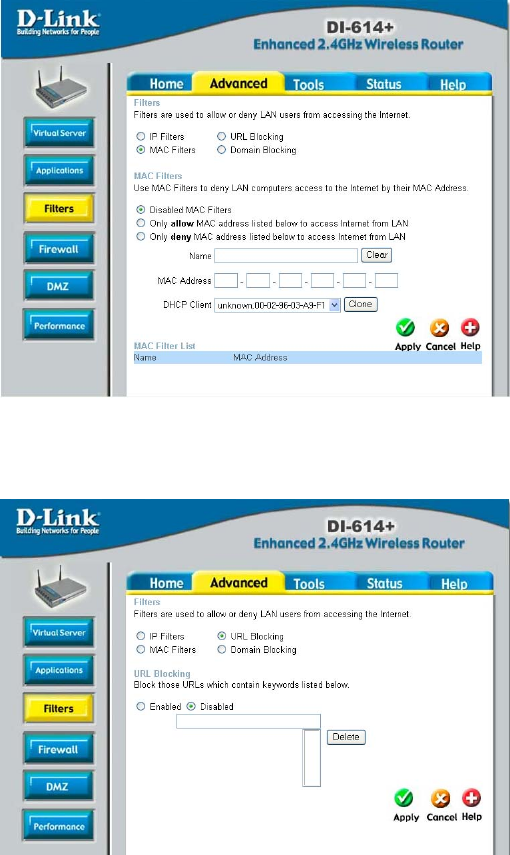
MAC Filters
Use MAC (Media
Access Control) Filters
to allow or deny LAN
(Local Area Network)
computers by their
MAC addresses from
accessing the Internet.
You can either
manually add a MAC
address or select the
MAC address from the
list of clients that are
currently connected to the Broadband Router.
URL Blocking
URL Blocking is used
to deny LAN computers
from accessing specific
web sites by its URL. A
URL is a specially
formatted text string
that defines a location
on the Internet. If any
part of the URL
contains the blocked
word, the site will not
be accessible and the
web page will not
display.
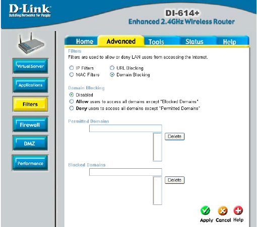
Domain Blocking
Domain Blocking is
used to allow or deny
LAN (Local Area
Network) computers
from accessing specific
domains on the
Internet. Domain
blocking will deny all
requests to a specific
domain such as http
and ftp. It can also
allow computers to
access specific sites
and deny all other sites.
26
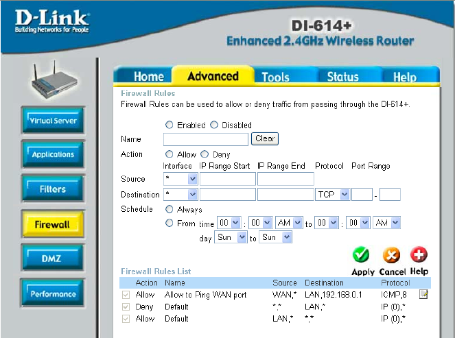
ADVANCED > FIREWALL
Firewall Rules is an advance feature used to deny or allow traffic from
passing through the Broadband Router. It works in the same way as IP
Filters with additional settings. You can create more detailed access rules for
the DI-614+. When virtual services are created and enabled, it will also
display in Firewall Rules. Firewall Rules contains all network firewall rules
pertaining to IP (Internet Protocol).
In the Firewall Rules List at the bottom of the screen, the priorities of the
rules are from top (highest priority) to bottom (lowest priority.)
Note: The DI-614+ MAC Address filtering rules have precedence over the
Firewall Rules.
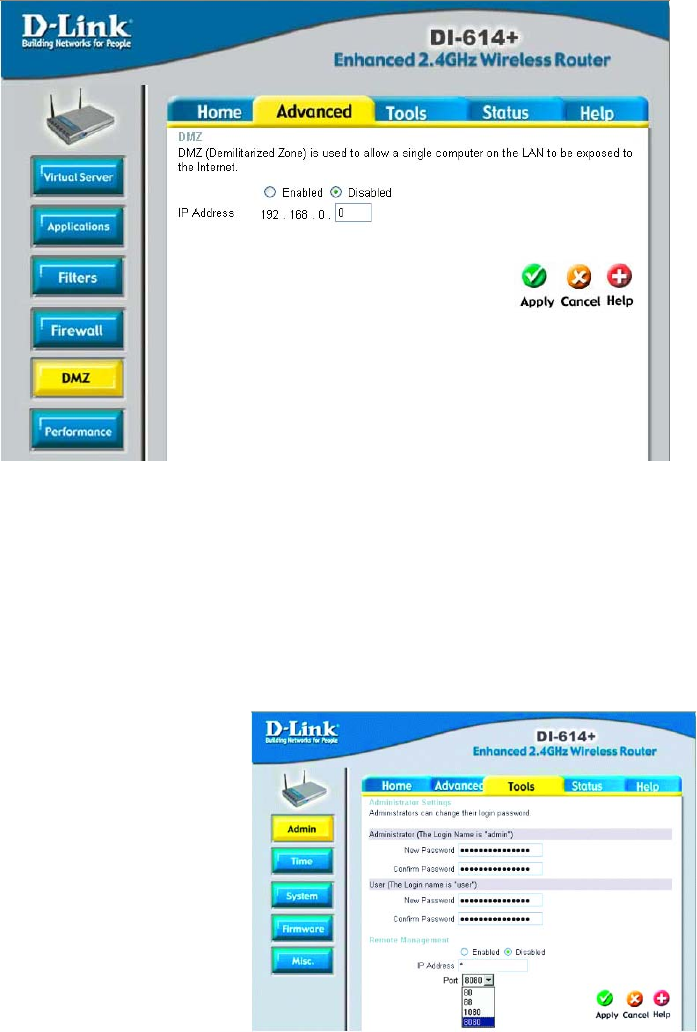
ADVANCED > DMZ
If you have a client PC that cannot run Internet applications properly from
behind the DI-614+, then you can set the client up to unrestricted Internet
access. It allows a computer to be exposed to the Internet. This feature is
useful for gaming purposes. Enter the IP address of the internal computer
that will be the DMZ host. Adding a client to the DMZ (Demilitarized Zone)
may expose your local network to a variety of security risks, so only use this
option as a last resort.
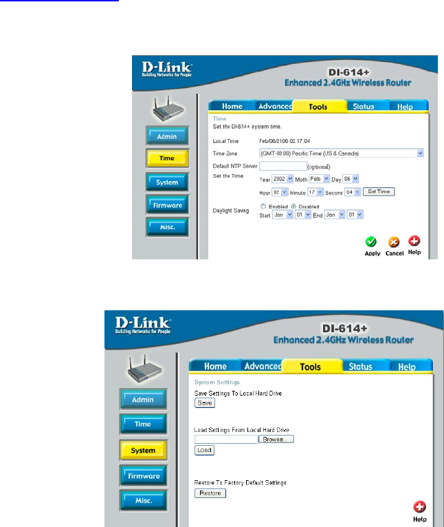
Admin
At this page, the DI-614+
administrator can change the
system password. There are
two accounts that can
access the Broadband
Router’s Web-Management
interface. They are admin
and user. Admin has
read/write access while user
has read-only access. User
can only view the settings
but cannot make any
changes.
TOOLS > ADMIN
28
Remote Management
Remote Management allows the DI-614+ to be configured from the Internet
by a web browser. A username and password is still required to access the
Web-Management interface. In general, only a member of your network can
browse the built-in web pages to perform “Administrator” tasks. This feature
enables you to perform “Administrator” tasks from the remote (Internet) host.
IP Address: Internet IP address of the computer that has access to the
Broadband Router. It is not recommended that you set the IP address to
* (star), because this allows any Internet IP address to access the
Broadband Router, which could result in a loss of security for your
network. If you elect to enable Remote Management, enter the IP Address
of your remote location.
Port: Select the port number used to access the Broadband Router.
Example: http://x.x.x.x:8080 whereas x.x.x.x is the WAN IP address of the
Broadband Router and 8080 is the port used for the Web-Management
interface.
Time
The system time is the time
used by the DI-614+ for
scheduling services. You can
manually set the time or
connect to a NTP (Network
Time Protocol) server. If an
NTP server is set, you will
only need to set the time
zone. If you manually set the
time, you may also set
Daylight Saving dates and
the system time will automatically adjust on those dates.
System Settings
The current system
settings can be saved as
a file onto the local hard
drive. The saved file or
any other saved setting
file can be loaded back
on the Broadband
Router. To reload a
system settings file, click
on Browse to browse the
TOOLS > TIME
TOOLS > SYSTEM
local hard drive and locate the system file to be used. You may also reset
the Broadband Router back to factory settings by clicking on Restore.
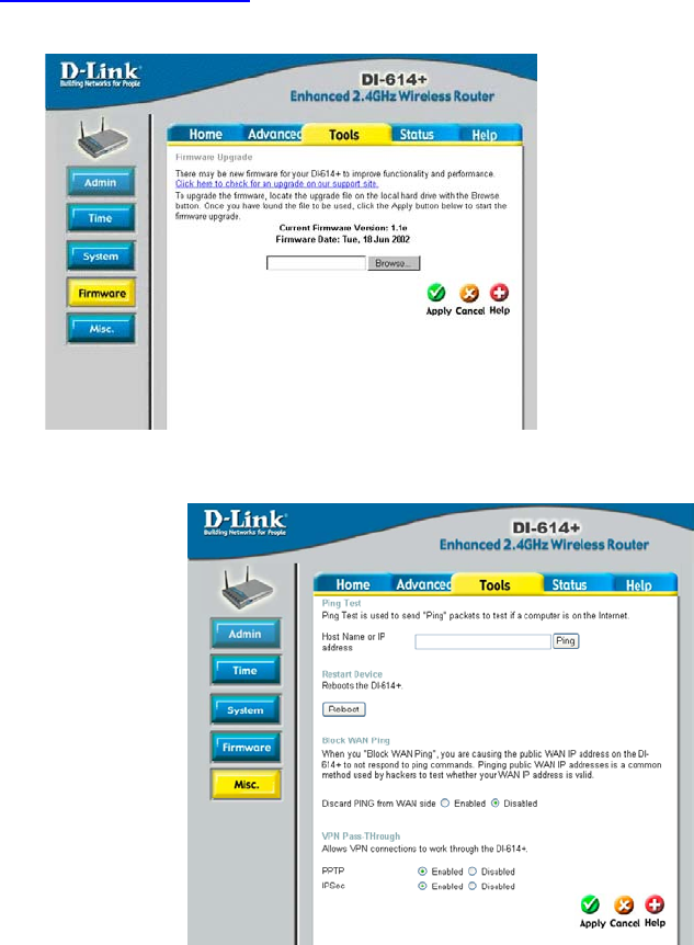
Firmware Upgrade
You can upgrade the firmware of the Broadband Router at this page. Make
sure the firmware you want to use is on the local hard drive of the computer.
Click on Browse to browse the local hard drive and locate the firmware to be
used for the update. Please check the D-Link support site for firmware
updates at http://support.dlink.com.
Miscellaneous Items
These are additional tools
and features of the
Broadband Router.
Ping Test
This useful diagnostic
utility can be used to
check if a computer is on
the Internet. It sends ping
packets and listens for
replies from the specific
host.
TOOLS > FIRMWARE
TOOLS > MISC
30
Restart Device
If for any reason the Broadband Router is not responding correctly, you may
want to restart the Broadband Router.
Block WAN Ping
When you “Block WAN Ping”, will not respond to ping commands from the
Internet. Pinging public WAN IP addresses is a common method used by
hackers to test whether your WAN IP address is valid.
Discard PING from WAN side: By enabling this option, the DI-614+ will not
reply to ping (ICMP) request packets from the Internet.
VPN Pass-Through
The Broadband Router supports VPN (Virtual Private Network) pass-through
for both PPTP (Point-to-Point Tunneling Protocol) and IPSec (IP Security).
Once VPN pass-through is enabled, there is no need to open up virtual
services. Multiple VPN connections can be made through the Broadband
Router. This is useful when you have many VPN clients on the LAN network.
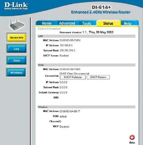
STATUS > DEVICE INFO
Device Information
This page in the
Configuration Utility
displays the current
information for the
Broadband Router. It will
display the WAN, LAN,
and MAC address
information.
If your WAN connection is
set up for Dynamic IP
address a Release button
and Renew button will be
displayed. Use Release to
disconnect from your ISP
and use Renew to
connect to your ISP.
If your WAN connection is set up for PPPoE, a Connect button and
Disconnect button will be displayed. Use Disconnect to drop the PPPoE
connection and use Connect to establish the PPPoE connection.
This page allows you to observe the DI-614+’s working status:
WAN
• IP Address: WAN/Public IP Address
• Subnet Mask: WAN/Public Subnet Mask
• Gateway: WAN/Public Gateway IP Address
• Domain Name Server: WAN/Public DNS IP Address
• Wan Status: WAN Connection Status
LAN
• IP Address: LAN/Private IP Address of the DI-614+
• Subnet Mask: LAN/Private Subnet Mask of the DI-614+
Firmware version: Displays the current firmware version
WAN MAC Address: Displays the WAN port MAC/hardware address
LAN MAC Address: Displays the LAN port MAC/hardware address
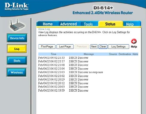
Log STATUS > LOG
The Broadband Router
keeps a running log of
events and activities
occurring on the Router. If
the device is rebooted, the
logs are automatically
cleared. You may save the
log files under Log
Settings.
First Page - The first page
of the log.
Last Page - The last page
of the log.
Previous - Moves back
one log page.
Next - Moves forward one log page.
Clear - Clears the logs completely.
Log Settings - Brings up the page to configure the logs.
32
Log Settings
Not only does the Broadband Router display the logs of activities and events,
it can be setup to send these logs to another location.
SMTP Server - The address of the SMTP server that will be used to send
the logs.
Send to - The email address the logs will be sent to. Click on Email Log Now
to send the email.
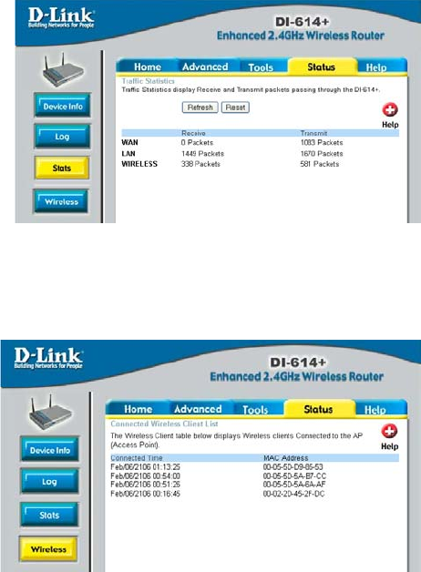
STATUS > STATS
Traffic Statistics
The Broadband Router
keeps statistic of traffic that
passes through it. You are
able to view the amount of
packets that passes through
the Router on both the WAN
port and the LAN port. The
traffic counter will reset if the
device is rebooted.
STATUS > WIRELESS
Connected Wireless
Clients List
The wireless client table
displays a list of current
connected wireless clients.
This table also displays the
time and MAC address of
the wireless client
connected.