D Link DI-764 Multimode 2.4/5GHz Wireless Router User Manual di764 manual 104
D Link Corporation Multimode 2.4/5GHz Wireless Router di764 manual 104
UserManual.wiki
>
D Link
>
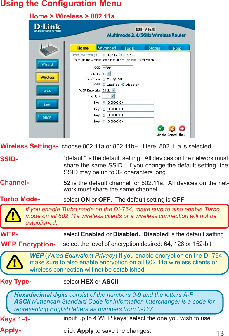
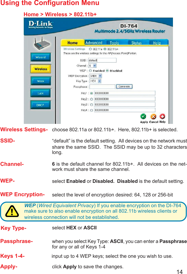
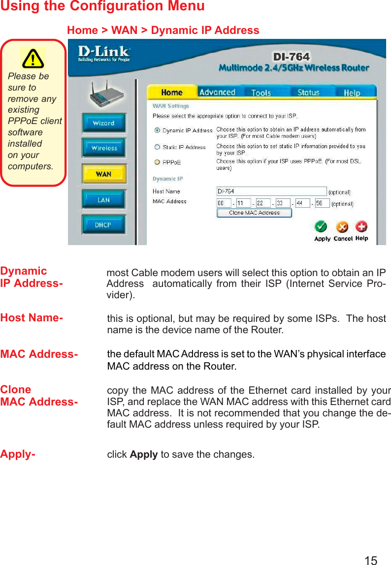
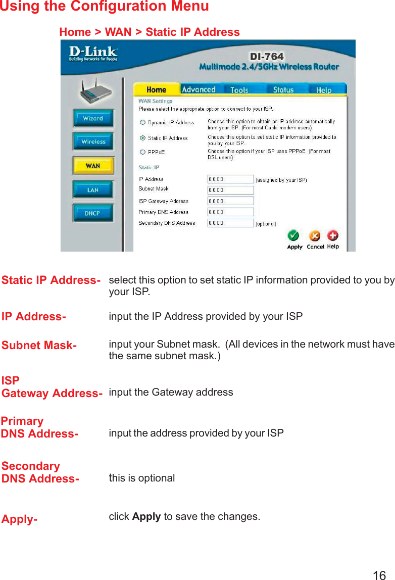
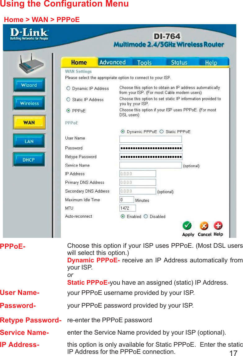
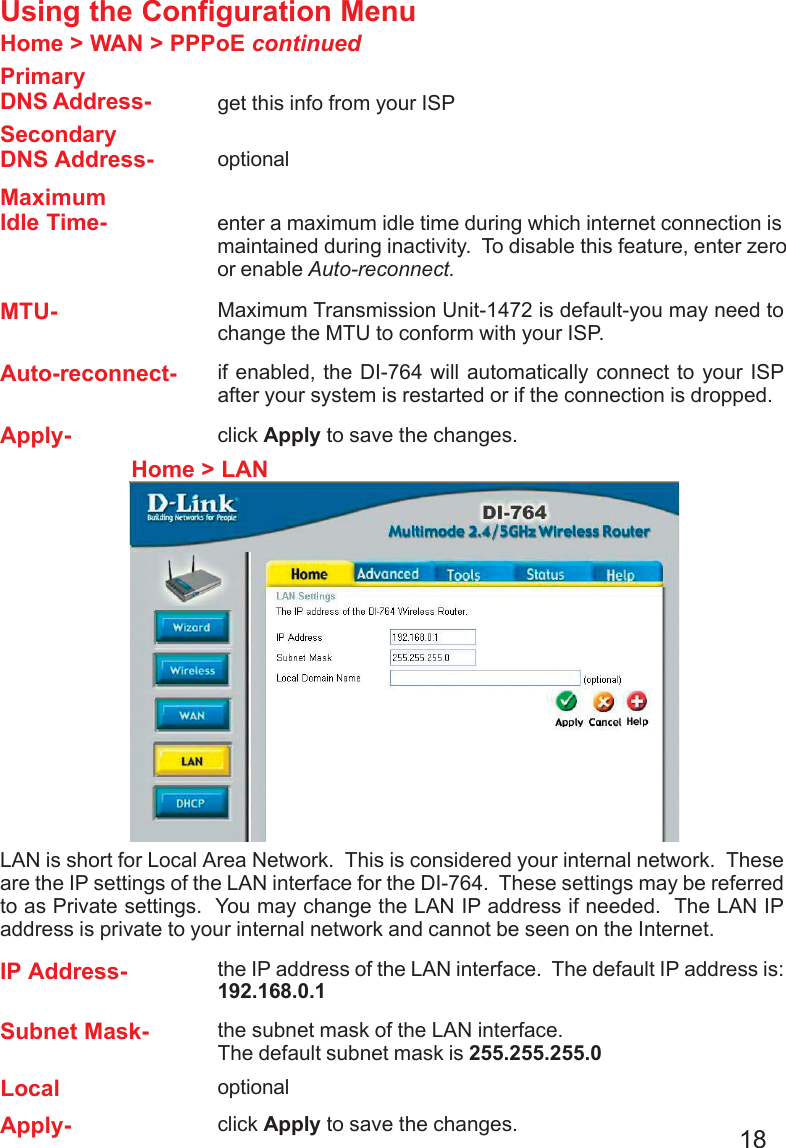
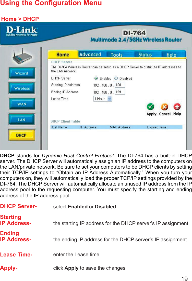
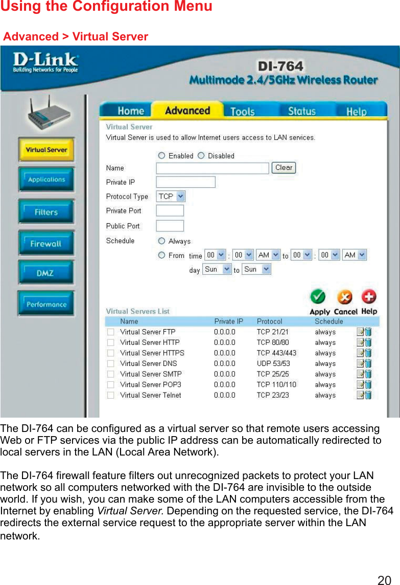
DI-764 User Manual
>
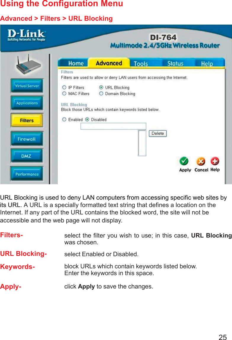
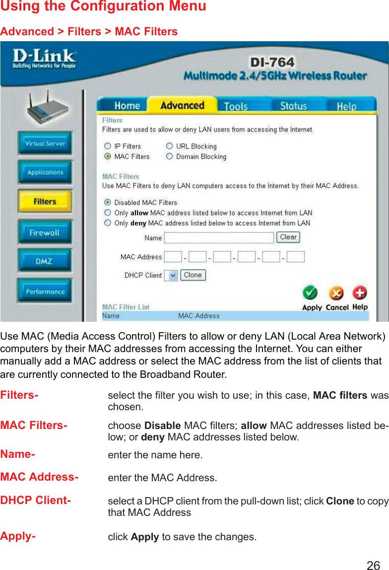
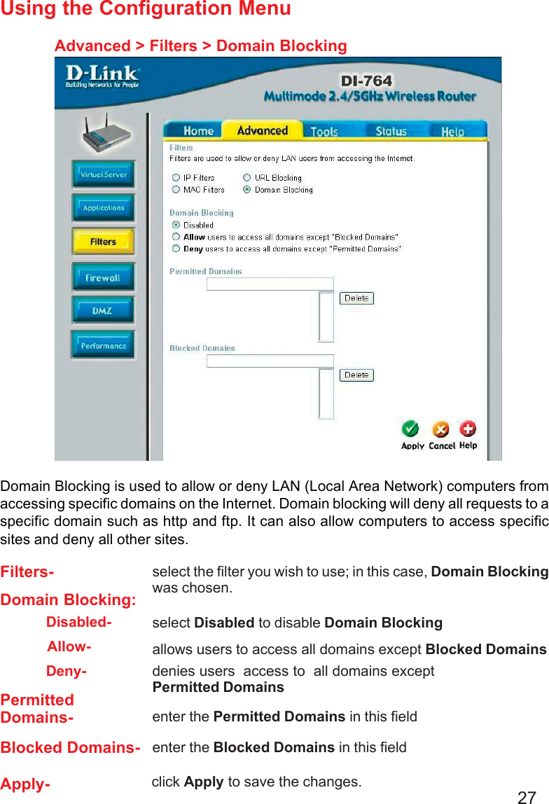
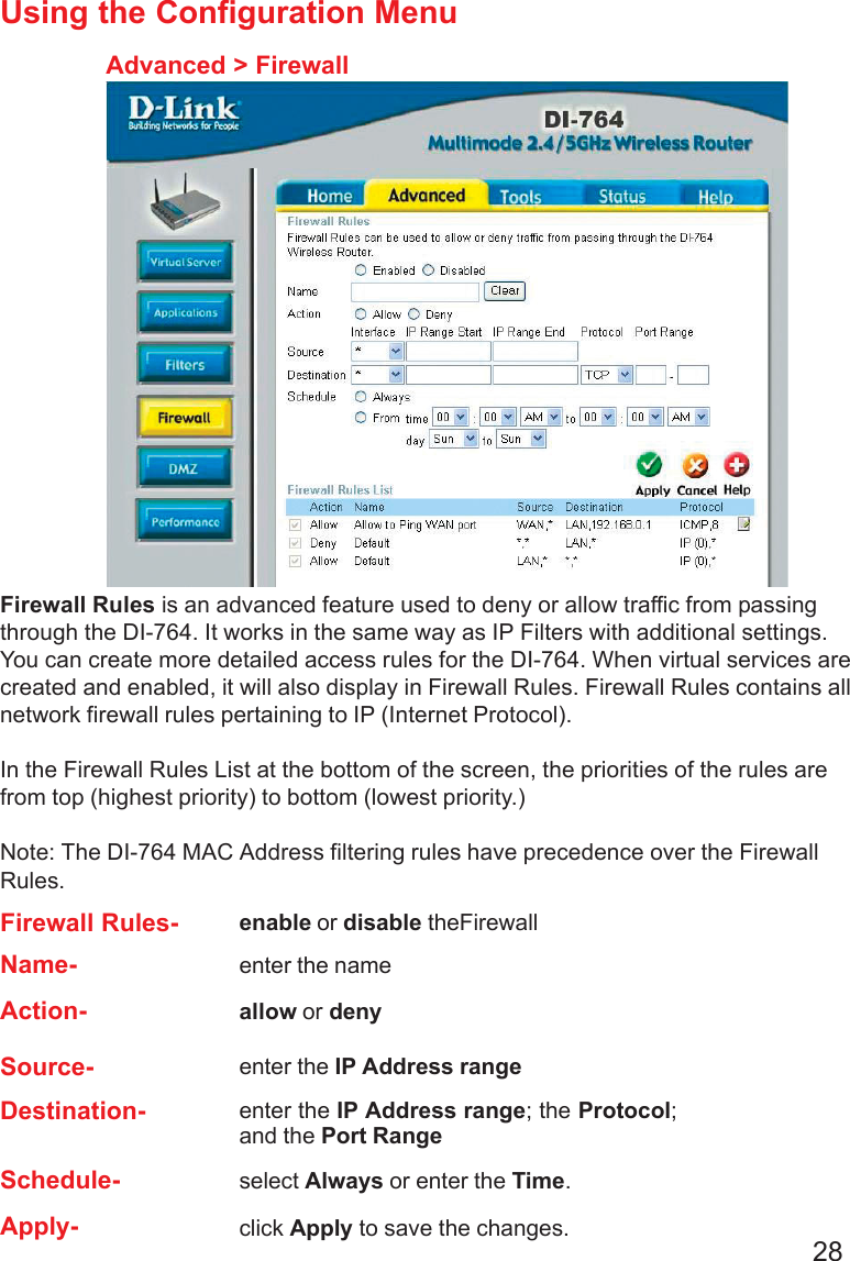
Part 1
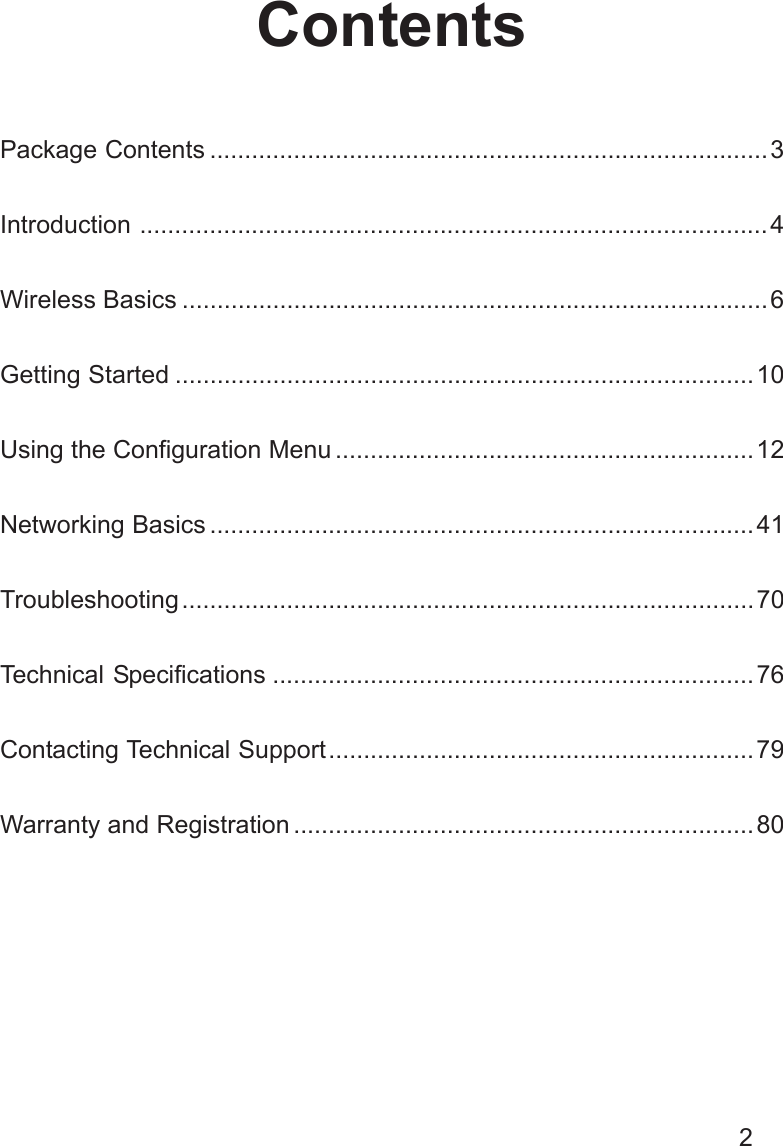
Contents
1.
Part 1
2.
Part 2
3.
Part 3
Part 1
Navigation menu
Upload a User Manual
Namespaces
Wiki Guide
HTML
PDF
Info
Views
User Manual
Discussion / Help
Navigation