D Link DI-764 Multimode 2.4/5GHz Wireless Router User Manual di764 manual 104
D Link Corporation Multimode 2.4/5GHz Wireless Router di764 manual 104
D Link >
Part 1

2.4 GHz / 5 GHz Multimode
Manual
Building Networks for People
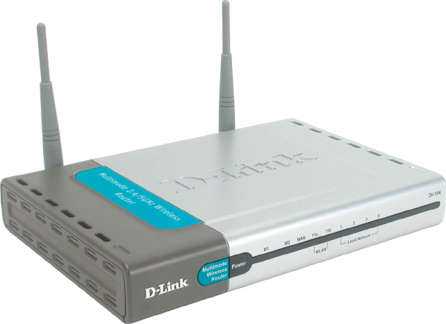
AirPro DI-764
Wireless Broadband Router
D-LINK
2
Contents
Package Contents ................................................................................3
Introduction ..........................................................................................4
Wireless Basics ....................................................................................6
Getting Started ...................................................................................10
Using the Configuration Menu ............................................................12
Networking Basics ..............................................................................41
Troubleshooting ..................................................................................70
Technical Specifications .....................................................................76
Contacting Technical Support.............................................................79
Warranty and Registration ..................................................................80
3
Contents of Package:
D-Link AirPro DI-764 2.4GHz/5GHz Multimode Wireless
Broadband Router
Power Adapter – 5V DC, 3.0A
Manual on CD
Quick Installation Guide
Ethernet Cable
Package Contents
Computer with Windows, Macintosh, or Linux-based
operating system with an installed Ethernet adapter
Note: Using a power supply with a different voltage rating than the one included with the
DI-764 will cause damage and void the warranty for this product.
If any of the above items are missing, please contact your reseller.
System Requirements For Configuration:
!
!
!
!
!
!
4
Introduction
D-Link, a leader in wireless technology, introduces the first integrated
multimode 2.4GHz/5GHz wireless broadband router, as part of the high
performance D-Link AirPro series of wireless networking products.
The new D-Link AirPro DI-764 Multimode Wireless Broadband Router is a
next generation multimode broadband router that simultaneously serves
both 802.11a wireless networks at 54 Mbps (72 Mbps in Turbo mode*) and
802.11b wireless networks at 11Mbps (22 Mbps with D-Link AirPlus
products.) Featuring a breakthrough all-in-one dual band design that
delivers future investment protection with the promise of a superior product
life cycle and lower total cost of ownership, it is the ideal solution for present
and future Wireless Local Area Networks (WLANs).
The DI-764 will automatically obtain an IP address and forward additional IP
addresses to multiple clients for a seamless Ethernet network connection
and shared Internet access.
At 54Mbps (up to 72Mbps in Turbo mode*) in the 5GHz frequency range and
a simultaneous 11 Mbps (up to 22 Mbps with D-Link AirPlus products) in the
2.4GHz frequency range, the D-Link AirPro DI-764 multimode broadband
router delivers the fastest standards-based wireless technology in the
industry. Based on WiFi technology, as well as IEEE 802.11a and 802.11b
standards compliant, this next-generation multimode wireless access point
provides excellent network interoperability.
Armed with powerful management and security capabilities, the D-Link Air
Pro DI-764 has an intuitive and secure web-based interface that is powered
by an embedded web server.
After completing the steps outlined in the Quick Installation Guide (included
in your package) not only will you have the ability to share information and
resources, but you will also be able to enjoy the freedom that wireless
networking delivers, at speeds capable of handling a video stream.
*When used with other D-Link AirPro products.
5
Because of its web-based interface (accessible from most Internet browser applications),
the DI-764 will work with most popular operating systems, including Macintosh, Linux
and Windows, and can be easily integrated into a large network. This Manual is designed
to help you connect the DI-764 with the D-Link 2.4GHz AirPlus or 5GHz AirPro Wireless
Adapters into an existing network. Please take a look at the Getting Started section in
this manual to see an example of an Infrastructure network using the DI-764.
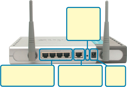
Connections
Features & Benefits
Supports data transfer rates of up to 72 Mbps at 5GHz
Supports data transfer rates of up to 22 Mbps at 2.4GHz
Wireless range of up to 900 feet*
Fully 802.11a and 802.11b compatible
Supports up to 256-bit WEP Encryption at 2.4GHz, and up to 152-bit, with
Enhanced Dynamic Keying at 5 GHz
Less interference with a total of eleven non-overlapping channels
Utilizes Direct Sequence Spread Spectrum (DSSS) and Packet Binary
Convolutional Code (PBCC) at 2.4GHz
Utilizes Orthogonal Frequency Division Multiplexing (OFDM) at 5GHz
!
!
!
!
!
!
!
!
Easy-to-use Web-based configuration
User level security
3 Year Warranty (USA only)
!
!
!
Pressing the
Reset Button
restores the
router to its
original factory
default settings.
Receptor
for the
Power
Adapter
The WAN port is the
connection for the
Ethernet cable to the
Cable or DSL modem
LAN ports automatically
sense cable type when
connecting to Ethernet-
enabled computers.
*Environmental Factors may Adversely Affect Range.

6
LEDS
LED stands for Light-Emitting Diode. The DI-764 has the following LEDs:
D-Link AirPro wireless products are based on industry standards to provide easy-to-
use and compatible high-speed wireless connectivity within your home, business or
public access wireless networks. Strictly adhering to the IEEE standard, the D-Link
AirPro wireless family of products will allow you to securely access the data you
want, when and where you want it. You will be able to enjoy the freedom that
wireless networking delivers.
A wireless local area network (WLAN) is a cellular computer network that transmits
and receives data with radio signals instead of wires. Wireless LANs are used
increasingly in both home and office environments, and public areas such as
airports, coffee shops and universities. Innovative ways to utilize WLAN technology
are helping people to work and communicate
Wireless Basics
LED LED Activity
A steady light indicates a connection to a power source
A solid light indicates that the unit is defective
A solid light indicates connection on the WAN port.
This LED blinks during data transmission.
A solid light indicates that the 802.11a wireless seg-
ment is ready. The LED blinks during 802.11a wireless
data transmission.
A solid light indicates that the DI-764 is ready
A solid light indicates a connection, a blinking light
indicates data transmission to an Ethernet-enabled
computer on ports 1-4.
Power
M1
M2
WAN
WLAN
802.11a
Local Network
(Ports 1-4)
WLAN
802.11b
A solid light indicates that the 802.11b wireless seg-
ment is ready (when the DWL-650+ is installed.) The
LED blinks during 802.11b wireless data transmission.
7
Wireless Basics
more efficiently. Increased mobility and the absence of cabling and other
fixed infrastructure have proven to be beneficial for many users.
Wireless users can use the same applications they use on a wired network.
Wireless adapter cards used on laptop and desktop systems support the
same protocols as Ethernet adapter cards.
Under many circumstances, it may be desirable for mobile network devices
to link to a conventional Ethernet LAN in order to use servers, printers or an
Internet connection supplied through the wired LAN. A Wireless Router is a
device used to provide this link.
People use wireless LAN technology for many different purposes:
Mobility - Productivity increases when people have access to data in any
location within the operating range of the WLAN. Management decisions
based on real-time information can significantly improve worker efficiency.
Low Implementation Costs – WLANs (Wireless Local Area Networks)
are easy to set up, manage, change and relocate. Networks that frequently
change, both physically and logically, can benefit from WLANs ease of
implementation. WLANs can operate in locations where installation of wiring
may be impractical.
Installation Speed and Simplicity - Installing a wireless LAN system
can be fast and easy and can eliminate the need to pull cable through walls
and ceilings.
Network Expansion - Wireless technology allows the network to go where
wires cannot go.
Scalability – Wireless Local Area Networks (WLANs) can be configured in
a variety of topologies to meet the needs of specific applications and
installations. Configurations are easily changed and range from peer-to-peer
networks suitable for a small number of users to larger infrastructure
networks to accommodate hundreds or thousands of users, depending on
the number of wireless devices deployed.
8
Wireless Basics
The DI-764 is compatible with other D-Link AirPro 802.11a products, which
include:
♦5GHz Wireless Cardbus Adapters used with laptop computers
(DWL-A650)
♦5GHz Wireless PCI Adapters used with desktop computers
(DWL-A520)
The DI-764 is also compatible with the D-Link AirPlus 802.11b wireless family,
which includes:
♦Enhanced 2.4GHz Wireless Cardbus Adapters used with laptop
computers (DWL-650+)
♦Enhanced 2.4GHz Wireless PCI cards used with desktop computers
(DWL-520+)
Standards-Based Technology
The versatile DI-764 Multimode Wireless Broadband Router integrates both
802.11a and 802.11b standards into a single unit.
The IEEE 802.11a standard designates that devices may operate at an
optimal data rate of 54 Mbps (72 Mbps in proprietary Turbo mode.) This
means that in most environments, within the specified range of this device,
you will be able to transfer large files quickly or even watch a movie in
MPEG format over your network without noticeable delays. This technology
works by transmitting high-speed digital data over a radio wave utilizing
OFDM (Orthogonal Frequency Division Multiplexing) technology. OFDM
works by splitting the radio signal into multiple smaller sub-signals that are
then transmitted simultaneously at different frequencies to the receiver.
OFDM reduces the amount of crosstalk (interference) in signal
transmissions. D-Link AirPro 802.11a products will automatically sense the
best possible connection speed to ensure the greatest speed and range
possible.
Based on the IEEE 802.11b standard, the DI-764 is also interoperable with
existing compatible 2.4GHz wireless technology with data transfer speeds of
up to 22Mbps (with the D-Link AirPlus family of wireless devices,) as well as
standard 802.11b technology ( the D-Link Air family of wireless devices),
with speeds of up to 11Mbps.
9
Wireless Basics
Installation Considerations
The D-Link AirPro DI-764 lets you access your network, using a wireless
connection, from virtually anywhere. Keep in mind, however, that the
number, thickness and location of walls, ceilings or other objects that the
wireless signals must pass through may limit the range. Typical ranges vary
depending on the types of materials and background RF (radio frequency)
noise in your home or business. The key to maximizing wireless range is to
follow these basic guidelines:
1. Keep the number of walls and ceilings between the DI-764 and your
receiving device (e.g., the DWL-A650 or the DWL-650+) to a minimum -
each wall or ceiling can reduce your D-Link AirPro Wireless product’s
range from 3-90 feet (1-30 meters.) Position your receiving devices so
that the number of walls or ceilings is minimized.
2. Be aware of the direct line between routers and computers. A wall that is
1.5 feet thick (.5 meters), at a 45-degree angle appears to be almost 3 feet
(1 meter) thick. At a 2-degree angle it looks over 42 feet (14 meters) thick!
Try to make sure that devices are positioned so that the signal will travel
straight through a wall or ceiling for better reception.
3. Building Materials make a difference - a solid metal door or aluminum
studs may have a negative effect on range. Try to position wireless
devices and computers with wireless adapters so that the signal passes
through drywall or open doorways and not other materials.
4. Keep your product away (at least 3-6 feet or 1-2 meters) from electrical
devices or appliances that generate RF noise.

10
With a single IP Address from your Broadband Internet Service provider you
can share the Internet with all the computers on your local network, without
sacrificing speed or security, using D-Link Air networking products.
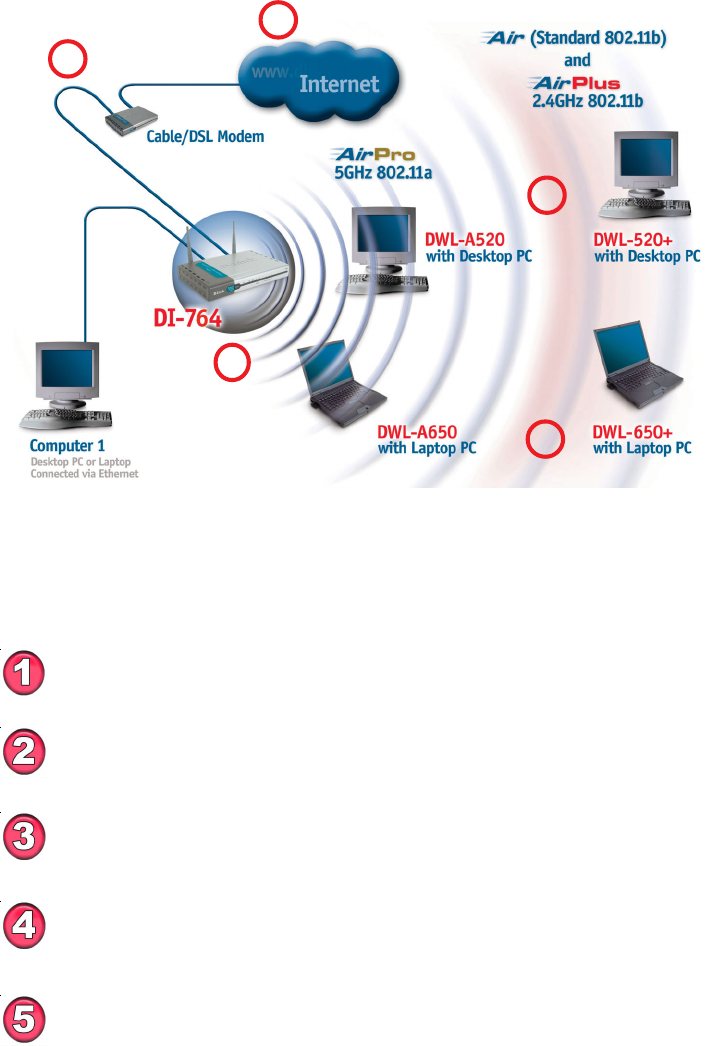
Getting Started
An Infrastructure wireless network contains an Access Point. The
Infrastructure Network example, shown here, contains the following D-Link
network devices:
A wireless Broadband Router - D-Link AirPro DI-764
A laptop computer with a wireless adapter - D-Link AirPro DWL-A650 or
AirPlus DWL-650+
A desktop computer with a wireless adapter - D-Link AirPro DWL-A520 or
AirPlus DWL-520+
A Cable modem - D-Link DCM-200
If you need to assign IP Addresses to the computers on the network,
please remember that the IP Address for each computer must be in
the same IP Address range as all the computers in the network, and
the Subnet mask must be exactly the same for all the computers in the
network.
For example: If the first computer is assigned an IP Address of
192.168.0.2 with a Subnet Mask of 255.255.255.0, then the second
computer can be assigned an IP Address of 192.168.0.3 with a Subnet
Mask of 255.255.255.0, etc.
IMPORTANT: If computers or other devices are assigned the same
IP Address, one or more of the devices may not be visible on the
network.
IP ADDRESS
Note: If you are using a DHCP-capable router in your network setup,
such as the DI-764, you will not need to assign a static IP Address.
Right out of the box, with its default settings, the DI-764 will
connect with other D-Link Air, AirPlus or AirPro products.
11
Please remember that D-Link AirPro wireless devices are pre-configured to connect
together, right out of the box, with the default settings.
You will need broadband Internet access (Cable/DSL) subscription
Consult with your Cable/DSL provider for proper installation of the modem
Connect the modem to the DI-764 multimode wireless broadband router
(see the Quick Installation Guide included with the DI-764.)
If you are connecting a desktop computer to your network, you can install the
D-Link AirPro DWL-A520 (or the DWL-520+) wireless PCI adapter into an
available PCI slot. (See the Quick Installation Guide included with the DWL-
A520 or the DWL-520+.)
If you are connecting a laptop computer to your network, install the drivers for the
wireless cardbus adapter (D-Link AirPro DWL-A650) into a laptop computer .
(See the Quick Installation Guide included with DWL-A650 or DWL-650+.)
Getting Started
For a typical wireless setup at home (as shown above), please do the
following:
5
1
3
4
2
12
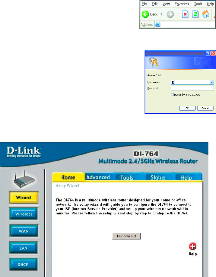
Using the Configuration Menu
Whenever you want to configure your network or the DI-764, you can access the
Configuration Menu by opening the web-browser and typing in the IP Address of the
DI-764. The DI-764 default IP Address is shown below:
!Open the web browser
!Type in the IP Address of
the Access Point
!Type admin in the User
Name field
Leave the Password
blank
Click Next
Home > Wizard
The Home>Wizard screen will appear. Please refer to the Quick Installation
Guide for more information regarding the Setup Wizard.
http://192.168.0.1
Connect to 192.168.0.1
admin
Note: if you have changed the default IP Address assigned to the DI-764, make sure to
enter the correct IP Address.
!
!
13
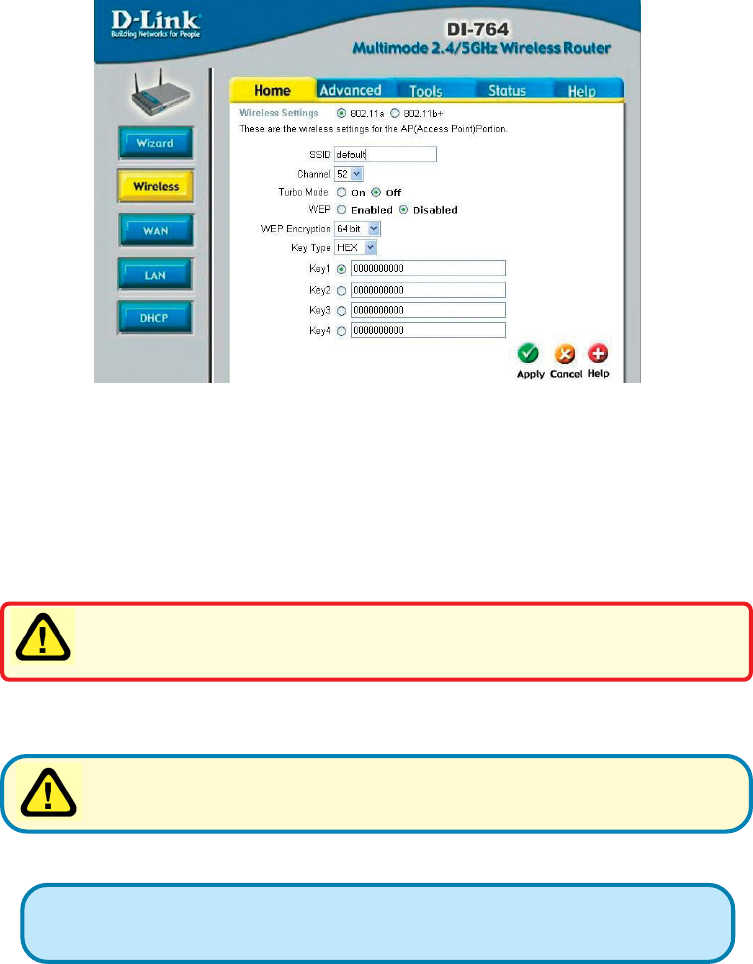
Home > Wireless > 802.11a
Using the Configuration Menu
SSID-
Channel-
Wireless Settings- choose 802.11a or 802.11b+. Here, 802.11a is selected.
“default” is the default setting. All devices on the network must
share the same SSID. If you change the default setting, the
SSID may be up to 32 characters long.
52 is the default channel for 802.11a. All devices on the net-
work must share the same channel.
Hexadecimal digits consist of the numbers 0-9 and the letters A-F
ASCII (American Standard Code for Information Interchange) is a code for
representing English letters as numbers from 0-127
Apply- click Apply to save the changes.
Keys 1-4- input up to 4 WEP keys; select the one you wish to use.
Key Type- select HEX or ASCII
WEP Encryption- select the level of encryption desired: 64, 128 or 152-bit
WEP- select Enabled or Disabled. Disabled is the default setting.
Turbo Mode- select ON or OFF. The default setting is OFF.
If you enable Turbo mode on the DI-764, make sure to also enable Turbo
mode on all 802.11a wireless clients or a wireless connection will not be
established.
WEP (Wired Equivalent Privacy) If you enable encryption on the DI-764
make sure to also enable encryption on all 802.11a wireless clients or
wireless connection will not be established.
14
Using the Configuration Menu
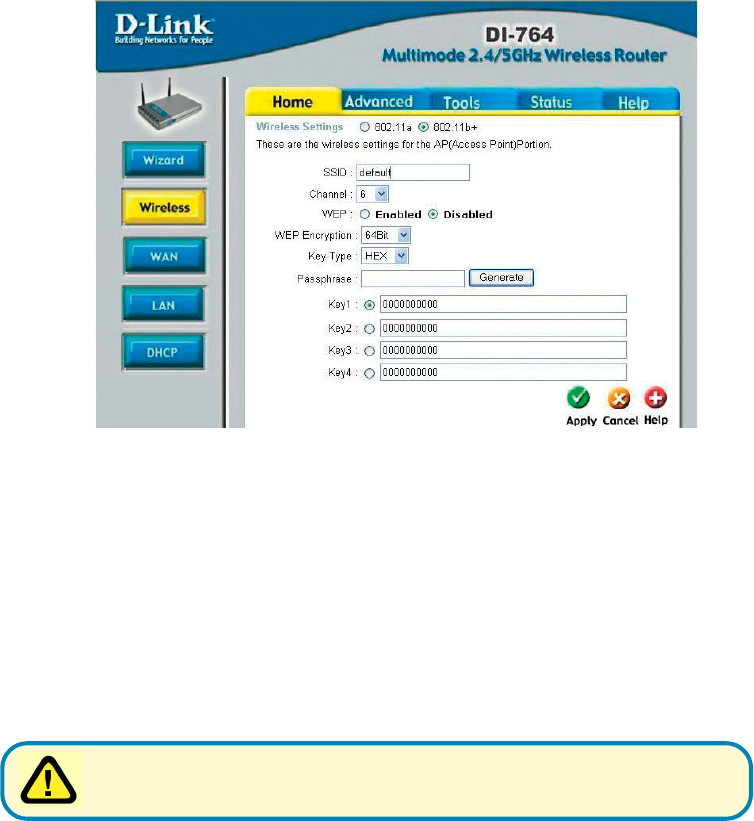
Home > Wireless > 802.11b+
Apply- click Apply to save the changes.
Keys 1-4- input up to 4 WEP keys; select the one you wish to use.
Passphrase- when you select Key Type: ASCII, you can enter a Passphrase
for any or all of Keys 1-4
Key Type- select HEX or ASCII
WEP Encryption- select the level of encryption desired: 64, 128 or 256-bit
WEP- select Enabled or Disabled. Disabled is the default setting.
Channel- 6 is the default channel for 802.11b+. All devices on the net-
work must share the same channel.
SSID- “default” is the default setting. All devices on the network must
share the same SSID. The SSID may be up to 32 characters
long.
Wireless Settings- choose 802.11a or 802.11b+. Here, 802.11b+ is selected.
WEP (Wired Equivalent Privacy) If you enable encryption on the DI-764
make sure to also enable encryption on all 802.11b wireless clients or
wireless connection will not be established.
15
Using the Configuration Menu
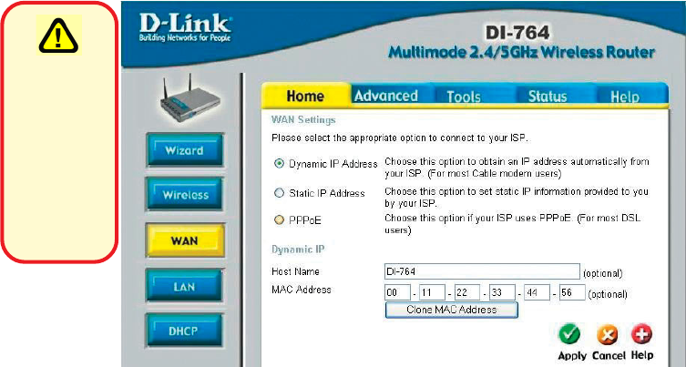
Home > WAN > Dynamic IP Address
Dynamic
IP Address-
Host Name-
MAC Address-
Clone
MAC Address-
Apply-
Please be
sure to
remove any
existing
PPPoE client
software
installed
on your
computers.
most Cable modem users will select this option to obtain an IP
Address automatically from their ISP (Internet Service Pro-
vider).
this is optional, but may be required by some ISPs. The host
name is the device name of the Router.
the default MAC Address is set to the WAN’s physical interface
MAC address on the Router.
copy the MAC address of the Ethernet card installed by your
ISP, and replace the WAN MAC address with this Ethernet card
MAC address. It is not recommended that you change the de-
fault MAC address unless required by your ISP.
click Apply to save the changes.
16
Using the Configuration Menu
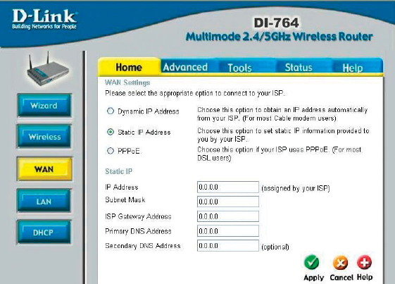
Home > WAN > Static IP Address
Static IP Address-
IP Address-
Subnet Mask-
ISP
Gateway Address-
Primary
DNS Address-
Secondary
DNS Address-
Apply-
select this option to set static IP information provided to you by
your ISP.
input the IP Address provided by your ISP
input your Subnet mask. (All devices in the network must have
the same subnet mask.)
input the Gateway address
input the address provided by your ISP
this is optional
click Apply to save the changes.
17
Using the Configuration Menu
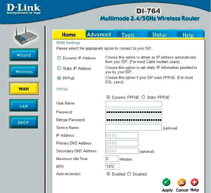
Home > WAN > PPPoE
PPPoE-
Static PPPoE-you have an assigned (static) IP Address.
Choose this option if your ISP uses PPPoE.
(Most DSL users
will select this option.)
Dynamic PPPoE- receive an IP Address automatically from
your ISP.
or
User Name- your PPPoE username provided by your ISP.
Password- your PPPoE password provided by your ISP.
Retype Password- re-enter the PPPoE password
Service Name- enter the Service Name provided by your ISP (optional).
IP Address- this option is only available for Static PPPoE. Enter the static
IP Address for the PPPoE connection.
18
Using the Configuration Menu
Home > WAN > PPPoE continued
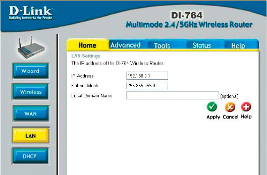
Home > LAN
LAN is short for Local Area Network. This is considered your internal network. These
are the IP settings of the LAN interface for the DI-764. These settings may be referred
to as Private settings. You may change the LAN IP address if needed. The LAN IP
address is private to your internal network and cannot be seen on the Internet.
Apply- click Apply to save the changes.
Auto-reconnect- if enabled, the DI-764 will automatically connect to your ISP
after your system is restarted or if the connection is dropped.
MTU- Maximum Transmission Unit-1472 is default-you may need to
change the MTU to conform with your ISP.
Maximum
Idle Time- enter a maximum idle time during which internet connection is
maintained during inactivity. To disable this feature, enter zero
or enable Auto-reconnect.
Secondary
DNS Address- optional
Primary
DNS Address- get this info from your ISP
Apply- click Apply to save the changes.
Local optional
Subnet Mask- the subnet mask of the LAN interface.
The default subnet mask is 255.255.255.0
IP Address- the IP address of the LAN interface. The default IP address is:
192.168.0.1
19
Using the Configuration Menu
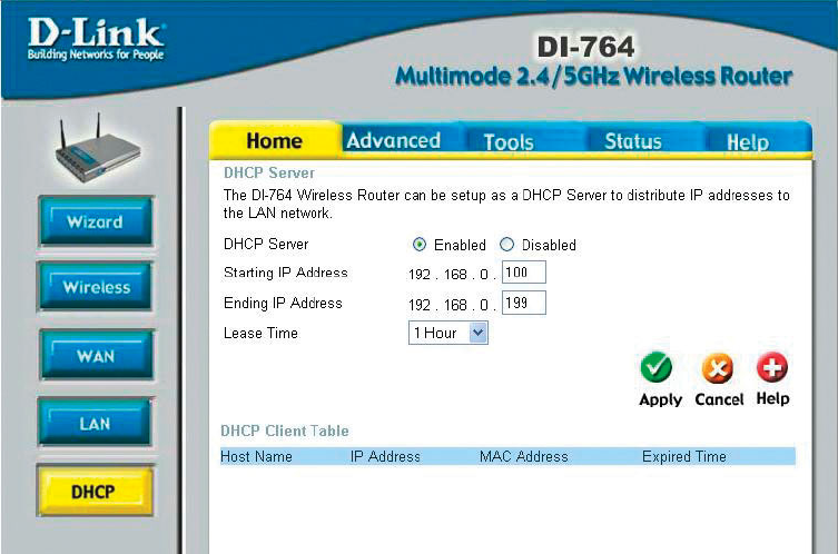
Home > DHCP
DHCP stands for Dynamic Host Control Protocol. The DI-764 has a built-in DHCP
server. The DHCP Server will automatically assign an IP address to the computers on
the LAN/private network. Be sure to set your computers to be DHCP clients by setting
their TCP/IP settings to “Obtain an IP Address Automatically.” When you turn your
computers on, they will automatically load the proper TCP/IP settings provided by the
DI-764. The DHCP Server will automatically allocate an unused IP address from the IP
address pool to the requesting computer. You must specify the starting and ending
address of the IP address pool.
DHCP Server- select Enabled or Disabled
Starting
IP Address- the starting IP address for the DHCP server’s IP assignment
Ending
IP Address- the ending IP address for the DHCP server’s IP assignment
Lease Time- enter the Lease time
Apply- click Apply to save the changes
20
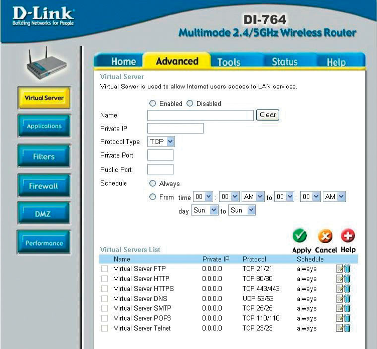
Advanced > Virtual Server
Using the Configuration Menu
The DI-764 can be configured as a virtual server so that remote users accessing
Web or FTP services via the public IP address can be automatically redirected to
local servers in the LAN (Local Area Network).
The DI-764 firewall feature filters out unrecognized packets to protect your LAN
network so all computers networked with the DI-764 are invisible to the outside
world. If you wish, you can make some of the LAN computers accessible from the
Internet by enabling Virtual Server. Depending on the requested service, the DI-764
redirects the external service request to the appropriate server within the LAN
network.
21
Advanced > Virtual Server continued
Using the Configuration Menu
The DI-764 is also capable of port-redirection meaning incoming traffic to a particular
port may be redirected to a different port on the server computer.
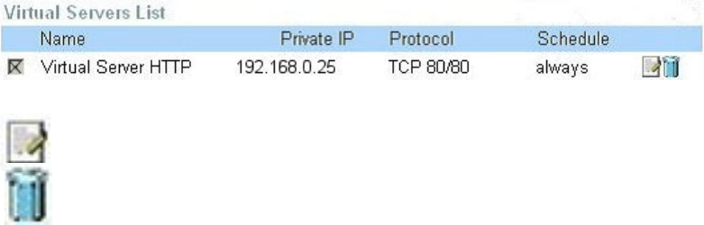
Each virtual service that is created will be listed at the bottom of the screen in the
Virtual Servers List. There are pre-defined virtual services already in the table. You
may use them by enabling them and assigning the server IP to use that particular
virtual service.
Example #1:
If you have a Web server that you wanted Internet users to access at all times, you
would need to enable it. Web (HTTP) server is on LAN (Local Area Network)
computer 192.168.0.25. HTTP uses port 80, TCP.
Name: Web Server
Private IP: 192.168.0.25
Protocol Type: TCP
Private Port: 80
Public Port: 80
Schedule: always
Protocol Type- the protocol used for the virtual service
Public Port- the port number on the WAN (Wide Area Network)side that will
be used to access the virtual service.
Private Port- the port number of the service used by the Private IP computer
Schedule- The schedule of time when the virtual service will be
enabled. The schedule may be set to Always, which will
allow the particular service to always be enabled. If it is set to
Time, select the time frame for the service to be enabled. If
the system time is outside of the scheduled time, the service
will be disabled.
Apply- click Apply to save the changes.
Virtual Server- select Enabled or Disabled
Name- enter the name referencing the virtual service
Private IP- the server computer in the LAN (Local Area Network) that will
be providing the virtual services.
22
Example #2:
If you have an FTP server that you wanted Internet users to access by WAN port
2100 and only during the weekends, you would need to enable it as such. FTP
server is on LAN computer 192.168.0.30. FTP uses port 21, TCP.
Name: FTP Server
Private IP: 192.168.0.30
Protocol Type: TCP
Private Port: 21
Public Port: 2100
Schedule: From: 01:00AM to 01:00AM, Sat to Sun
Using the Configuration Menu
Advanced > Virtual Server continued
Click on this icon to edit the virtual service
Click on this icon to delete the virtual service
All Internet users who want to access this FTP Server
must connect to it from port 2100. This is an example of
port redirection and can be useful in cases where there
are many of the same servers on the LAN network.
23
Using the Configuration Menu
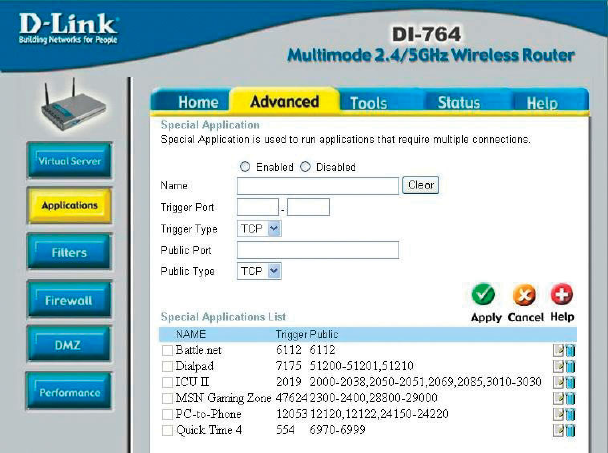
Advanced > Applications
Some applications require multiple connections, such as Internet gaming, video
conferencing, Internet telephony and others. These applications have difficulties
working through NAT (Network Address Translation). Special Applications makes
some of these applications work with the DI-764. If you need to run applications that
require multiple connections, specify the port normally associated with an application
in the “Trigger Port” field, select the protocol type as TCP or UDP, then enter the
public ports associated with the trigger port to open them for inbound traffic.
The DI-764 provides some predefined applications in the table on the bottom of the
web page. Select the application you want to use and enable it.
Note! Only one PC can use each Special Application tunnel.
Name: this is the name referencing the special application.
Trigger Port: this is the port used to trigger the application. It can be either
a single port or a range of ports.
Trigger Type: this is the protocol used to trigger the special application.
Public Port: this is the port number on the WAN side that will be used to
access the application. You may define a single port or a
range of ports. You can use a comma to add multiple ports or
port ranges.
Public Type: this is the protocol used for the special application.
Apply: click Apply to save the changes
24
Using the Configuration Menu
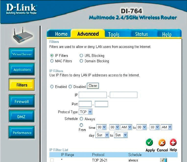
Advanced > Filters > IP Filters
Filters are used to deny or allow LAN (Local Area Network) computers from accessing
the Internet. The DI-764 can be setup to deny internal computers by their IP or MAC
addresses. The DI-764 can also block users from accessing restricted web sites.
click Apply to save changes.
Apply:
this is the schedule of time when the IP Filter will be enabled.
Schedule:
select the protocol typeProtocol Type:
the single port or port range that will be denied access to the
Internet.
Port:
Use IP Filters to deny LAN IP addresses from accessing the
Internet. You can deny specific port numbers or all ports for
the specific IP address.
IP Filters
the IP address of the LAN computer that will be denied
access to the Internet.
IP:
25
Using the Configuration Menu
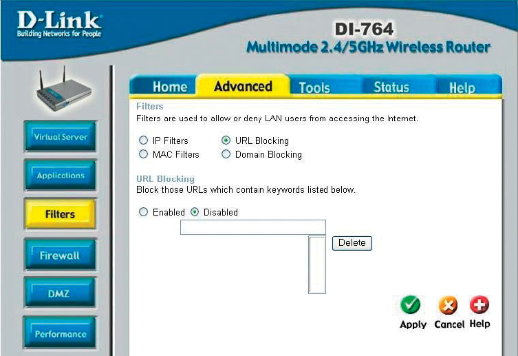
Advanced > Filters > URL Blocking
Filters-
URL Blocking is used to deny LAN computers from accessing specific web sites by
its URL. A URL is a specially formatted text string that defines a location on the
Internet. If any part of the URL contains the blocked word, the site will not be
accessible and the web page will not display.
select the filter you wish to use; in this case, URL Blocking
was chosen.
Apply- click Apply to save the changes.
Keywords- block URLs which contain keywords listed below.
Enter the keywords in this space.
URL Blocking- select Enabled or Disabled.
26
Using the Configuration Menu
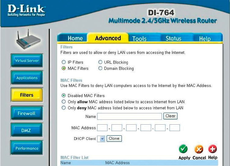
Advanced > Filters > MAC Filters
Use MAC (Media Access Control) Filters to allow or deny LAN (Local Area Network)
computers by their MAC addresses from accessing the Internet. You can either
manually add a MAC address or select the MAC address from the list of clients that
are currently connected to the Broadband Router.
MAC Filters- choose Disable MAC filters; allow MAC addresses listed be-
low; or deny MAC addresses listed below.
Filters- select the filter you wish to use; in this case, MAC filters was
chosen.
Name- enter the name here.
MAC Address- enter the MAC Address.
DHCP Client- select a DHCP client from the pull-down list; click Clone to copy
that MAC Address
Apply- click Apply to save the changes.
27
Using the Configuration Menu
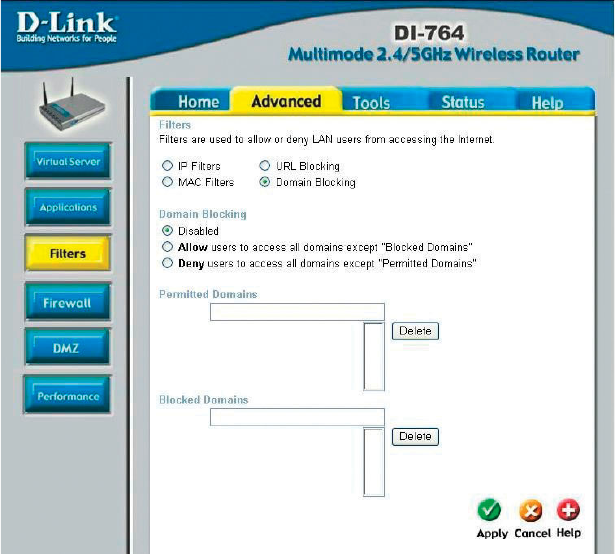
Advanced > Filters > Domain Blocking
Filters-
Domain Blocking:
Blocked Domains-
Permitted
Domains-
Apply-
Domain Blocking is used to allow or deny LAN (Local Area Network) computers from
accessing specific domains on the Internet. Domain blocking will deny all requests to a
specific domain such as http and ftp. It can also allow computers to access specific
sites and deny all other sites.
select the filter you wish to use; in this case, Domain Blocking
was chosen.
Disabled-
Allow-
Deny-
enter the Permitted Domains in this field
enter the Blocked Domains in this field
click Apply to save the changes.
select Disabled to disable Domain Blocking
allows users to access all domains except Blocked Domains
denies users access to all domains except
Permitted Domains
28
Using the Configuration Menu
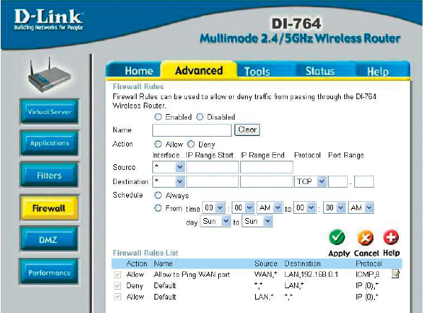
Advanced > Firewall
Schedule-
Apply-
Firewall Rules is an advanced feature used to deny or allow traffic from passing
through the DI-764. It works in the same way as IP Filters with additional settings.
You can create more detailed access rules for the DI-764. When virtual services are
created and enabled, it will also display in Firewall Rules. Firewall Rules contains all
network firewall rules pertaining to IP (Internet Protocol).
In the Firewall Rules List at the bottom of the screen, the priorities of the rules are
from top (highest priority) to bottom (lowest priority.)
Note: The DI-764 MAC Address filtering rules have precedence over the Firewall
Rules.
select Always or enter the Time.
click Apply to save the changes.
Firewall Rules-
Name-
Action-
Source-
enable or disable theFirewall
enter the name
allow or deny
enter the IP Address range
Destination- enter the IP Address range; the Protocol;
and the Port Range
29
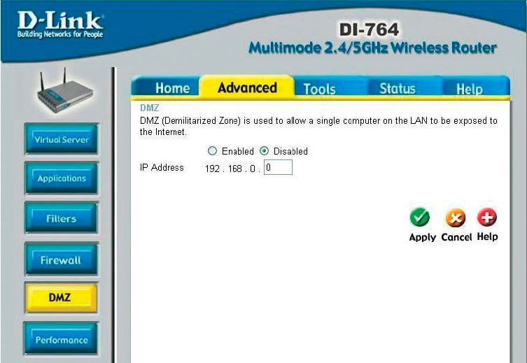
Advanced > DMZ
Using the Configuration Menu
If you have a client PC that cannot run Internet applications properly from behind the
DI-764, then you can set the client up to unrestricted Internet access. It allows a
computer to be exposed to the Internet. This feature is useful for gaming purposes.
Enter the IP address of the internal computer that will be the DMZ host. Adding a
client to the DMZ (Demilitarized Zone) may expose your local network to a variety of
security risks, so only use this option as a last resort.
DMZ-
IP Address-
Apply-
enable or disable the DMZ. The DMZ (Demilitarized Zone)
allows a single computer to be exposed to the internet.
enter the IP Address of the computer to be in the DMZ
click Apply to save the changes.
30
Using the Configuration Menu
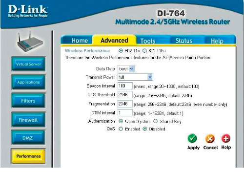
Advanced > Performance > 802.11a
Apply- click Apply to save the changes
DTIM interval- (Delivery Traffic Indication Message) 1 is the default setting. A
DTIM is a countdown informing clients of the next window for
listening to broadcast and multicast messages.
RTS Threshold- this value should remain at its default setting of 2342. If incon-
sistent data flow is a problem, only a minor modification should
be made.
Beacon interval- beacons are packets sent by the DI-764 to synchronize a wire-
less network. Specify a value. 100 is the default setting and is
recommended.
Data Rate- best is the default selection
Transmit Power- full is the default selection.
Wireless
Performance- select 802.11a or 802.11b+. Here, 802.11a has been
chosen. This screen displays the wireless performance
features of the Access Point portion of the DI-764.
Fragmentation- this value should also remain at its default setting of 2346. If
you experience a high packet error rate, you may slightly in-
crease your Fragmentation value within the range of 256-2346.
Setting the Fragmentation value too low may result in poor per-
formance.
Shared Key - in this mode, in order to access the DI-764 on the network, the
device must be listed in the MAC Address Control List
Open System - the DI-764 will be visible to all devices on the network. This is
the default setting
Authentication- select Open system or Shared Key
31
Using the Configuration Menu
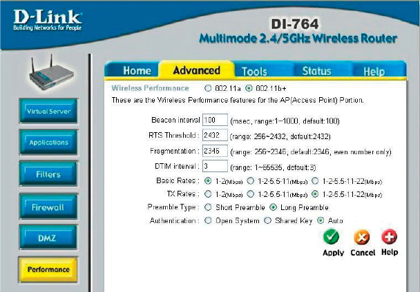
Advanced > Performance > 802.11b+
Beacon interval- beacons are packets sent by the DI-764 to synchronize a wire-
less network. Specify a value. 100 is the default setting and is
recommended.
Basic Rates- choose from1-2Mbps; 1,2,5.5,11 Mbps; or 1,2,5.5,11,22 Mbps
RTS Threshold- this value should remain at its default setting of 2342. If incon-
sistent data flow is a problem, only a minor modification should
be made.
Fragmentation- this value should also remain at its default setting of 2346. If
you experience a high packet error rate, you may slightly in-
crease your Fragmentation value within the range of 256-2346.
Setting the Fragmentation value too low may result in poor per-
formance.
Wireless
Performance-
Select 802.11a or 802.11b+. 802.11b+ is selected here. Dis-
played in this window are the Wireless Performance features
for the Access Point portion of the DI-764.
DTIM interval- (Delivery Traffic Indication Message) 3 is the default setting. A
DTIM is a countdown informing clients of the next window for
listening to broadcast and multicast messages.
TX Rates- select the basic transfer rates based on the speed of the wire-
less adapters on the WLAN (wireless local area network);
choose from among the same ranges as those listed in the Basic
Rates,above.
32
Using the Configuration Menu
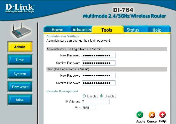
Tools> Admin
Apply- click Apply to save changes
Shared Key - in this mode, in order to access the DI-764 on the network, the
device must be listed in the MAC Address Control List
Open System - the DI-764 will be visible to all devices on the network. This is
the default setting
Authentication- select Open system or Shared Key
Preamble Type- select Short or Long Preamble. The Preamble Type defines
the length of the CRC (Cyclic Redundancy Check) block for
communication between the DI-764 and roaming wireless adapt-
ers. Make sure to select the appropriate preamble type and
click Apply. Note: High network traffic areas should use the
shorter preamble type. CRC is a common technique for de-
tecting data transmission errors.
Administrator
Login Name
admin is the default login name for the Admin account
User
Login Name
user is the default login name for the User account
Admin Password- the default setting is blank - no password. To change the pass-
word, enter and confirm the new password.
User Password- the default setting is blank - no password. To change the pass-
word, enter and confirm the new password.
33
Using the Configuration Menu
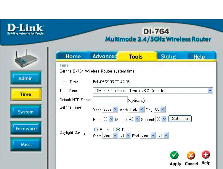
Tools > Time
Remote Management
Remote Management allows the DI-764 to be configured from the Internet by a web
browser. A username and password is still required to access the Web-Management
interface. In general, only a member of your network can browse the built-in web
pages to perform “Administrator” tasks. This feature enables you to perform
“Administrator” tasks from the remote (Internet) host.
IP Address: Internet IP address of the computer that has access to the Router. It is
not recommended that you set the IP address to * (star), because this allows any
Internet IP address to access the Router, which could result in a loss of security for
your network. If you elect to enable Remote Management, make sure to enter the
IP Address of the remote computer allowed to configure the DI-764.
Port: For security purposes, select a separate port number used to access the
Router. (The following is an example only; you may use a different port number.)
Example: http://x.x.x.x:8080 where x.x.x.x is the WAN IP address of the Router
and 8080 is the port used for the Web-Management interface.
Default
NTP Server-
NTP is short for Network Time Protocol. NTP synchronizes com-
puter clock times in a network of computers.
This field is optional.
Time settings- in this window you can choose the time zone; set the time;
and enable or disable Daylight Savings Time.
34
Using the Configuration Menu
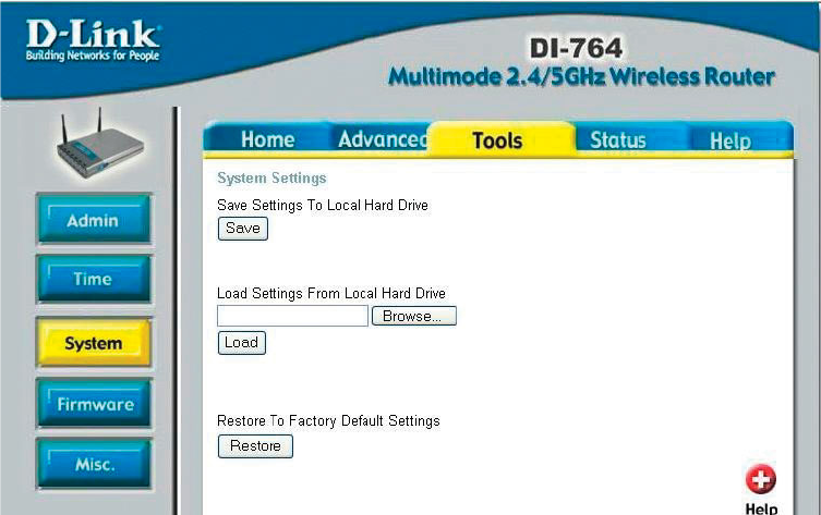
Tools > System
System Settings
click Save to save the current settings to the local Hard Drive
click Browse to find the settings, then click Load
Save Settings to
Local Hard Drive-
Load Settings from
Local Hard Drive-
Restore to Factory
Default Settings- click Restore to restore the factory default settings
35
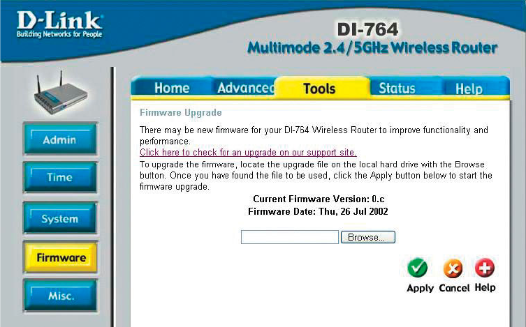
Using the Configuration Menu
Tools > Firmware
Firmware Upgrade-
Browse-
click on the link in this screen to find out if there is an updated
firmware; if so, download the new firmware to your hard drive.
after you have downloaded the new firmware, click Browse in
this window to locate the firmware update on your hard drive.
Click Apply to complete the firmware upgrade.
36
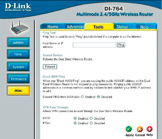
Using the Configuration Menu
Tools > Misc
Ping Test-
Restart Device-
Block WAN Ping-
Discard Ping
from WAN side-
VPN
Pass Through-
PPTP- select Enabled or Disabled
IPSec- select Enabled or Disabled
Apply-
the Ping Test is used to send Ping packets to test if a computer
is on the Internet. Enter the IP Address that you wish to Ping,
and click Ping
if you choose to block WAN Ping, the WAN IP Address of the
DI-764 will not respond to pings. Blocking the Ping may provide
some extra security from hackers.
the DI-764 supports VPN (Virtual Private Network) pass-through
for both PPTP (Point-to-Point Tunneling Protocol) and IPSec
(IP Security). Once VPN pass-through is enabled, there is no
need to open up virtual services. Multiple VPN connections
can be made through the DI-764. This is useful when you have
many VPN clients on the LAN network.
click Reboot to restart the DI-764
click Enabled to block the WAN ping
click Apply to save changes
37
Using the Configuration Menu
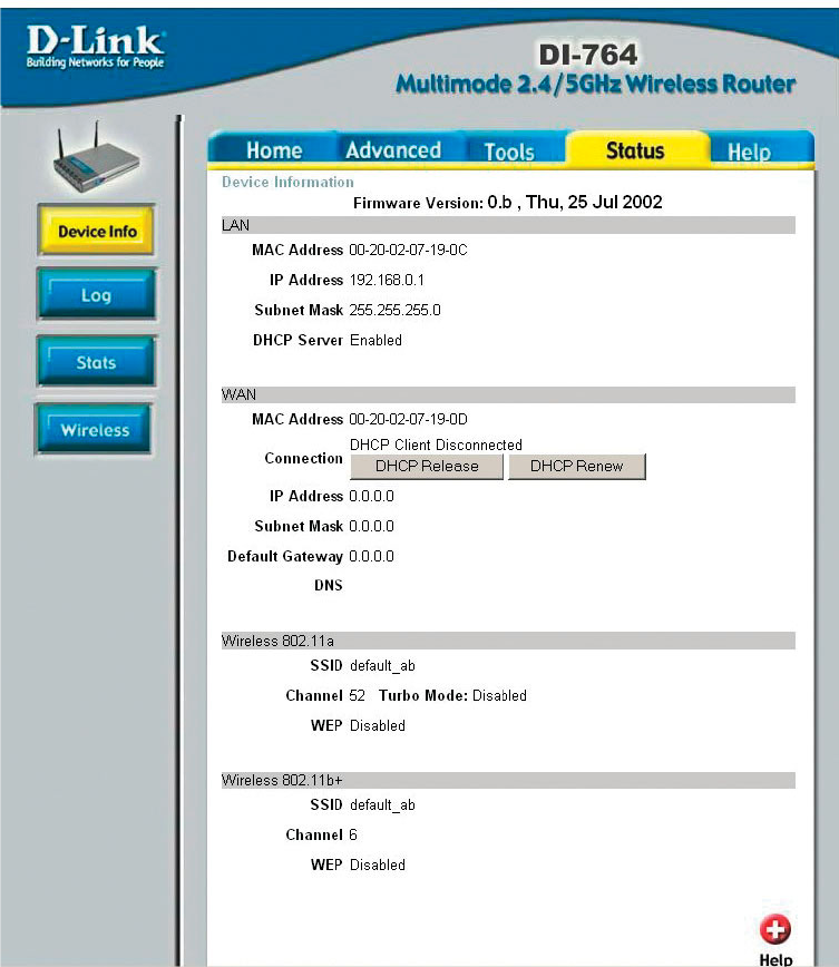
Status > Device Info
Device Information- This screen displays information about the DI-764
38
Using the Configuration Menu
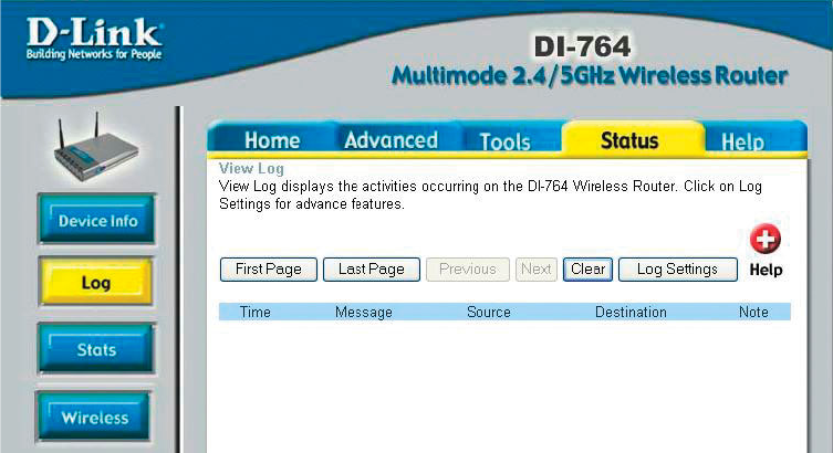
Status > Log
View Log-
Log Settings-
this screen displays the activity on the DI-764
for advanced features, click on Log Settings
39
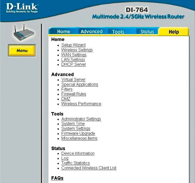
Status > Wireless
Connected
Wireless
Client List-
Using the Configuration Menu
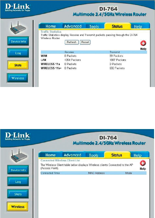
Status > Stats
Traffic Statistics- displays the receive and transmit packets that are passing
through the DI-764. Click on Refresh or Reset, for the most
recent information.
displays the wireless clients that are connected
to the Access Point function of the DI-764.
40
Using the Configuration Menu
Help
Help- displays the complete Help menu. For help at anytime, click
the Help tab in the Configuration menu.