D Link DI774VB1 Tri-Mode Dualband Wireless Router User Manual di764 manual 104
D Link Corporation Tri-Mode Dualband Wireless Router di764 manual 104
D Link >
Contents
- 1. Users Manual 1
- 2. Users Manual 2
- 3. Users Manual 3
Users Manual 1

2.4 GHz / 5 GHz Tri-Mode Dualband
Manual
Building Networks for People
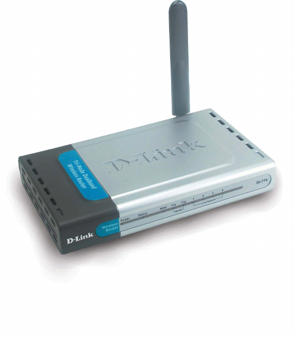
D-Link Air Xpert DI-774
Wireless Router
2
Contents
Package Contents ................................................................................3
Introduction............................................................................................4
Connections..........................................................................................5
Features ...............................................................................................6
LEDs ....................................................................................................7
Wireless Basics ....................................................................................8
Getting Started ....................................................................................10
Using the Configuration Menu.............................................................. 11
Networking Basics ..............................................................................40
Troubleshooting...................................................................................55
Technical Specifications ......................................................................61
Frequently Asked Questions ................................................................64
Contacting Technical Support ..............................................................92
Warranty and Registration ...................................................................93
3
Contents of Package:
D-Link Air Xpert DI-774 2.4GHz/5GHz Tri-Mode Dualband
Wireless Router
Power Adapter – 5V DC, 3.0A
Manual on CD
Quick Installation Guide
Ethernet Cable
Package Contents
Computer with Windows, Macintosh, or Linux-based
operating system with an installed Ethernet adapter
Note: Using a power supply with a different voltage rating than the one included with the
DI-774 will cause damage and void the warranty for this product.
If any of the above items are missing, please contact your reseller.
System Requirements For Configuration:
!
!
!
!
!
!
4
Introduction
At up to five times the speed of previous wireless devices, you can work faster and more
efficiently, increasing productivity. With the DI-774, bandwidth-intensive applications like
graphics or multimedia will benefit significantly because large files are able to move
across the network quickly. This versatile wireless router also features four times the
number of non-overlapping channels than a device that supports only 802.11g, so more
users can access the network.
Support for all three standards (802.11g; 802.11a; 802.11b) means that you can grow
your network without having to worry about legacy wireless equipment being incompatible
with newer compliant devices from other manufacturers. This also allows network
administrators to partition the usage of the dualband by segmenting users and creating
special access privilege networks for classified document transfer and communications.
With the DI-774 you can securely connect to wireless clients on the network using
802.1x for wireless user authentication, as well as WPA (Wi-Fi Protected Access )
providing you a much higher level of security for your data and communications than
has previously been available.
Through its easy-to-use Web-based user interface, the DI-774 lets you control the
information that is accessible to those on the wireless network, whether from the Internet
or from your company’s server:
Content Filtering – Easily applied content filtering based on MAC Address, IP Address,
URL and /or Domain Name.
Filter Scheduling – Filters can be scheduled to be active on certain days or for a
duration of hours or minutes.
Network Address Translation – NAT protects the DI-774 and its users from outside
intruders gaining access to your private network
VPN Multiple/Concurrent Sessions – Supports multiple and concurrent IPSec and
PPTP sessions, so multiple users behind the DI-774 can access corporate networks
through various VPN clients more securely.
TM
5
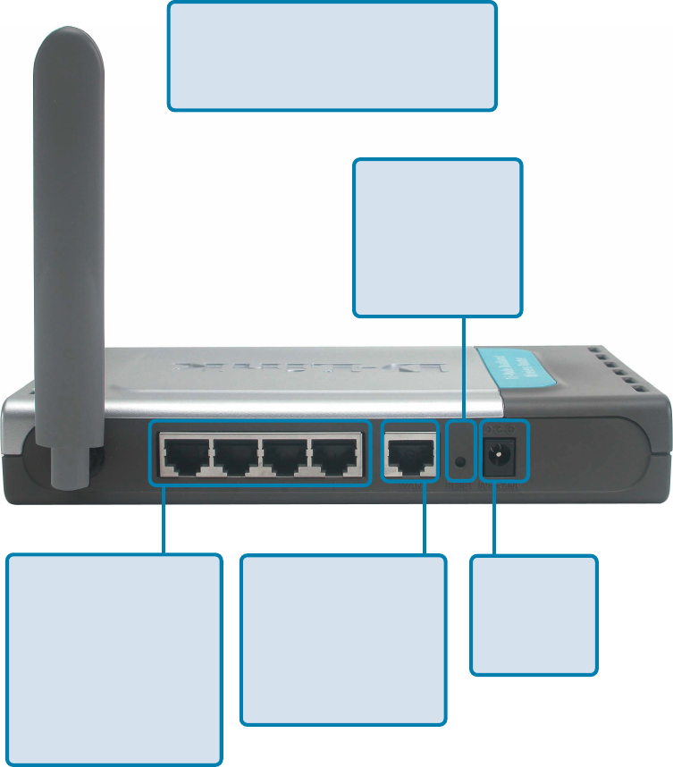
Connections - Back Panel of Unit
All Ethernet Ports (WAN and LAN)
are auto MDI/MDIX, meaning you can
use either a straight-through or a
crossover Ethernet cable.
Auto MDI/MDIX
LAN ports
automatically
sense the cable
type when
connecting to
Ethernet-enabled
computers.
The Auto MDI/MDIX
WAN port is the
connection for the
Ethernet cable to
the Cable or DSL
modem
Receptor
for the
Power
Adapter
Pressing the
Reset Button
restores the
router to its
original factory
default settings.
6
Features
TM
!Connects multiple computers to a Broadband (Cable or DSL) modem to
share the Internet connection
!IP Filtering
!Advanced Firewall features
!DHCP server supported enables all networked computers to automatically
receive IP addresses
!Web-based interface for Managing and Configuring
Access Control to manage users on the network
!
!Supports special applications that require multiple connections
!Equipped with 4 10/100 Ethernet ports, 1 WAN port, Auto MDI/MDIX
!URL Filtering
!Domain Blocking
!Scheduling
!Supports NAT with VPN pass-through, providing added security
!MAC Filtering
Operates in the 2.4GHz frequency range
!
!User-friendly configuration and diagnostic utilities
!Utilizes OFDM technology (Orthogonal Frequency Division Multiplexing) to
ensure strong wireless signals for both 802.11g and 802.11a
802.1x Authentication in conjunction with the RADIUS server verifies the
identity of would be clients
!
WPA (Wi Fi Protected Access ) authorizes and identifies users based on a
secret key that changes automatically at a regular interval, for example:
!Backwards compatible with the 802.11b standard to provide a wireless data
rate of up to 11Mbps
!
Fully compatible with the 802.11g standard to provide a wireless data rate of
up to 54Mbps
!
!
!TKIP (Temporal Key Integrity Protocol), in conjunction with a RADIUS
server, changes the temporal key every 10,000 packets, ensuring greater
security
Pre-Shared Key mode means that the home user, without a RADIUS
server, will obtain a new security key every time the he or she connects
to the network, vastly improving the safety of communications on the
network.
7
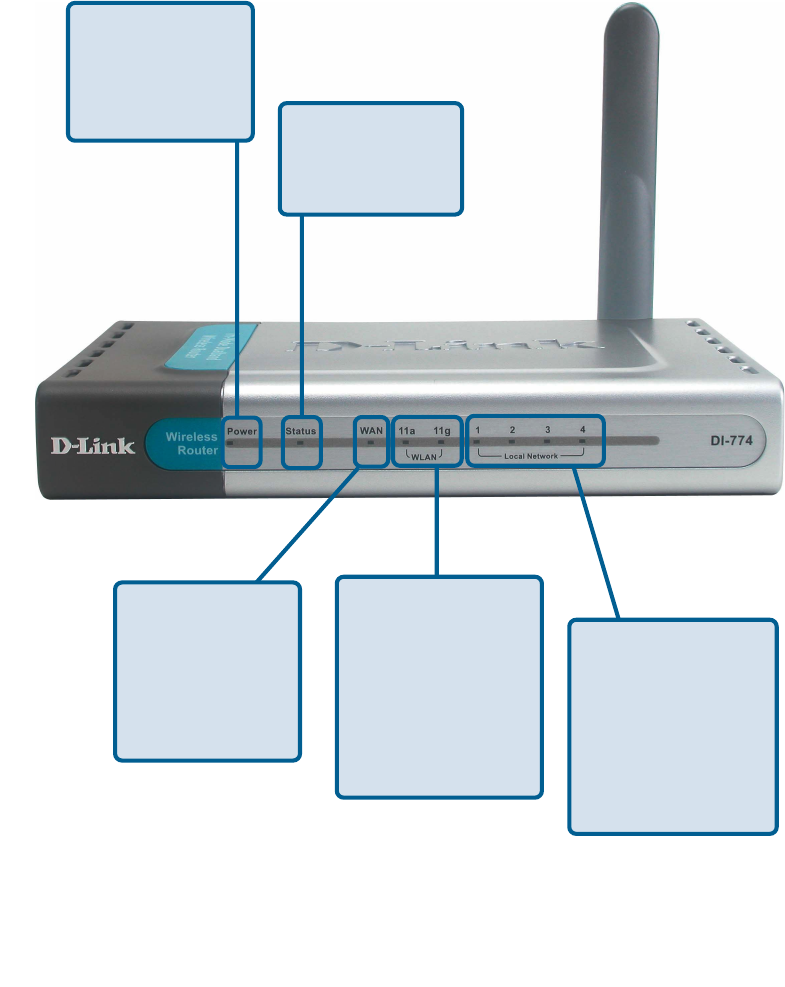
LEDs - Front Panel of Unit
LED stands for Light-Emitting Diode. The DI-774 has the following LEDs:
WLAN LEDs for 11a
and 11g wireless net-
work segments.
A solid light indi-
cates that the
wireless segment is
ready. The LEDs
blink during wireless
data transmission
WAN LED
A solid light
indicates connec-
tion on the WAN
port. This LED
blinks during data
transmission
Local
Network LEDs
A solid light indicates
a connection to an
Ethernet-enabled
computer on ports 1-
4. The LEDs blink
during data transmis-
sion
Status
A blinking light
indicates that the
DI-774 is ready
Power
A solid light
indicates a proper
connection to the
power supply
8
Wireless Basics
D-Link wireless products are based on industry standards to provide easy-to-use and
compatible high-speed wireless connectivity within your home, business or public access
wireless networks. D-Link wireless products will allow you access to the data you want,
when and where you want it. You will be able to enjoy the freedom that wireless networking
brings.
A WLAN is a cellular computer network that transmits and receives data with radio
signals instead of wires. WLANs are used increasingly in both home and office
environments, and public areas such as airports, coffee shops and universities. Innovative
ways to utilize WLAN technology are helping people to work and communicate more
efficiently. Increased mobility and the absence of cabling and other fixed infrastructure
have proven to be beneficial for many users.
Wireless users can use the same applications they use on a wired network. Wireless
adapter cards used on laptop and desktop systems support the same protocols as
Ethernet adapter cards.
People use wireless LAN technology for many different purposes:
Mobility - Productivity increases when people have access to data in any location
within the operating range of the WLAN. Management decisions based on real-time
information can significantly improve worker efficiency.
Low Implementation Costs – WLANs are easy to set up, manage, change and
relocate. Networks that frequently change can benefit from WLANs ease of
implementation. WLANs can operate in locations where installation of wiring may be
impractical.
Installation and Network Expansion - Installing a WLAN system can be fast
and easy and can eliminate the need to pull cable through walls and ceilings. Wireless
technology allows the network to go where wires cannot go - even outside the home or
office.
Scalability – WLANs can be configured in a variety of topologies to meet the needs of
specific applications and installations. Configurations are easily changed and range
from peer-to-peer networks suitable for a small number of users to larger infrastructure
networks to accommodate hundreds or thousands of users, depending on the number
of wireless devices deployed.
Inexpensive Solution - Wireless network devices are as competitively priced as
conventional Ethernet network devices.
9
Standards-Based Technology
The DI-774 Wireless Broadband Router utilizes the new 802.11g standard, in addition
to the 802.11a and 802.11b standards.
The IEEE 802.11g standard is an extension of the 802.11b standard. It increases the
data rate up to 54 Mbps within the 2.4GHz band, utilizing OFDM technology.
This means that in most environments, within the specified range of this device, you will
be able to transfer large files quickly or even watch a movie in MPEG format over your
network without noticeable delays. This technology works by transmitting high-speed
digital data over a radio wave utilizing OFDM (Orthogonal Frequency Division Multiplexing)
technology. OFDM works by splitting the radio signal into multiple smaller sub-signals
that are then transmitted simultaneously at different frequencies to the receiver. OFDM
reduces the amount of crosstalk (interference) in signal transmissions.
.
Wireless Basics (continued)
Installation Considerations
The D-Link Air Xpert DI-774 lets you access your network, using a wireless connection,
from virtually anywhere within its operating range. Keep in mind, however, that the number,
thickness and location of walls, ceilings, or other objects that the wireless signals must
pass through, may limit the range. Typical ranges vary depending on the types of materials
and background RF (radio frequency) noise in your home or business. The key to
maximizing wireless range is to follow these basic guidelines:
Keep the number of walls and ceilings between the DI-624 and other network
devices to a minimum - each wall or ceiling can reduce your D-Link wireless
product’s range from 3-90 feet (1-30 meters.) Position your devices so that
the number of walls or ceilings is minimized.
11
11
1
Be aware of the direct line between network devices. A wall that is 1.5 feet
thick (.5 meters), at a 45-degree angle appears to be almost 3 feet (1 meter)
thick. At a 2-degree angle it looks over 42 feet (14 meters) thick! Position
devices so that the signal will travel straight through a wall or ceiling (instead
of at an angle) for better reception.
22
22
2
Building Materials can impede the wireless signal - a solid metal door or
aluminum studs may have a negative effect on range. Try to position wireless
devices and computers with wireless adapters so that the signal passes
through drywall or open doorways and not other materials.
33
33
3
Keep your product away (at least 3-6 feet or 1-2 meters) from electrical
devices or appliances that generate extreme RF noise.
44
44
4
10
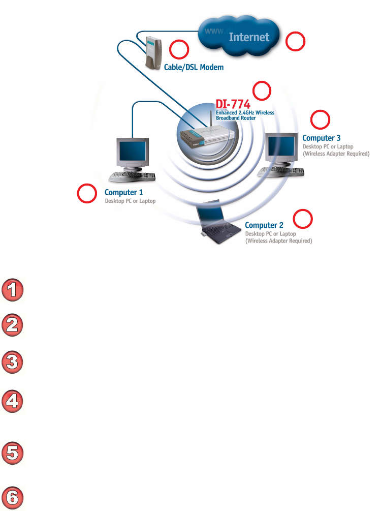
Getting Started
Setting up a
Wireless
Infrastructure
Network
5
1
4
2
6
3
You will need broadband Internet access (a Cable or DSL-subscriber line into
your home or office)
Consult with your Cable or DSL provider for proper installation of the modem
Connect the Cable or DSL modem to the DI-774 Wireless Router (see the
printed Quick Installation Guide included with your router.)
If you are connecting a desktop computer to your network, install the D-Link Air
Xpert DWL-AG520 wireless PCI adapter into an available PCI slot on your
desktop computer.
(See the printed Quick Installation Guide included with the network adapter.)
Install the D-Link DWL-AG650 wireless Cardbus adapter into a laptop computer.
(See the printed Quick Installation Guide included with the DWL-AG650.)
Install the D-Link DFE-530TX+ wireless Cardbus adapter into a desktop com-
puter. The four Ethernet LAN ports of the DI-774 are Auto MDI/MDIX and will
work with both Straight-through and Crossover cable.
(See the printed Quick Installation Guide included with the DFE-530TX+.)
For a typical wireless setup at home (as shown above),
please do the following:
11
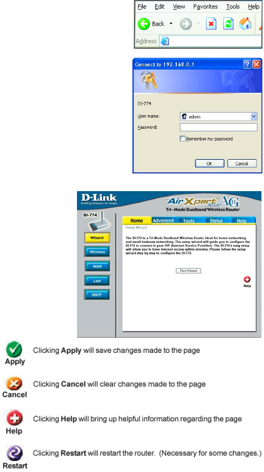
Whenever you want to configure your network or the DI-774, you can access the
Configuration Menu by opening the web-browser and typing in the IP Address of the
DI-774. The DI-774 default IP Address is shown here:
!Open the web browser
!Type in the IP Address of
the Router (http://192.168.0.1)
!Type admin in the User
Name field
Leave the Password
blank
Click OK
!
Using the Configuration Menu
Home > Wizard
The Home>Wizard screen will appear.
Please refer to the Quick Installation
Guide for more information regarding the
Setup Wizard.
Note: if you have changed the default IP Address
assigned to the DI-774, make sure to enter the
correct IP Address.
!
These buttons appear
on most of the configu-
ration screens in this
section. Please click on
the appropriate button
at the bottom of each
screen after you have
made a configuration
change.
http://192.168.0.1
12
Using the Configuration Menu (continued)
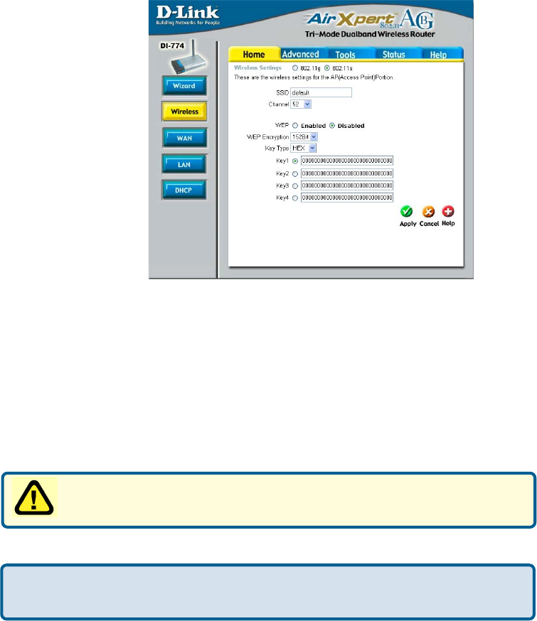
Home > Wireless > 802.11a
SSID-
Channel-
Wireless Settings- Choose 802.11a or 802.11g. Here, 802.11a is selected.
“default” is the default setting. All devices on the network must
share the same SSID. If you change the default setting, the
SSID may be up to 32 characters long.
52 is the default channel for 802.11a. All devices on the network
must share the same channel.
Hexadecimal digits consist of the numbers 0-9 and the letters A-F
ASCII (American Standard Code for Information Interchange) is a code for repre-
senting English letters as numbers from 0-127
Keys 1-4- Input up to 4 WEP keys; select the one you wish to use.
Key Type- Select HEX or ASCII
WEP (Wired Equivalent Privacy) If you enable encryption on the DI-774
make sure to also enable encryption on all 802.11a wireless clients or
wireless connection will not be established.
WEP Encryption- Select the level of encryption desired: 64, 128 or 152-bit
WEP- Select Enabled or Disabled. Disabled is the default setting.
13
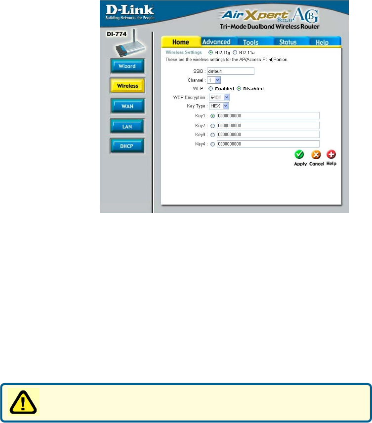
Using the Configuration Menu (continued)
Home > Wireless > 802.11g
Key Type- Select HEX or ASCII
WEP- Select Enabled or Disabled. Disabled is the default setting.
Channel- 1 is the default channel for 802.11g. All devices on the network
must share the same channel.
SSID- “default” is the default setting. All devices on the network must
share the same SSID. The SSID may be up to 32 characters
long.
Wireless Settings- Choose 802.11a or 802.11g. Here, 802.11g is selected.
WEP (Wired Equivalent Privacy) If you enable encryption on the DI-774
make sure to also enable encryption on all 802.11g wireless clients or
wireless connection will not be established.
Keys 1-4- Input up to 4 WEP keys; select the one you wish to use.
WEP Encryption- Select the level of encryption desired: 64, 128 or 152-bit
14
Using the Configuration Menu (continued)
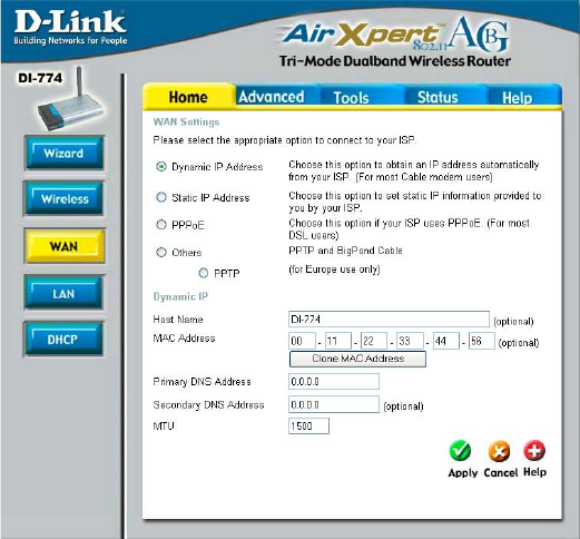
Home > WAN > Dynamic IP Address
Dynamic
IP Address- Most Cable modem users will select this option to obtain an IP
Address automatically from their ISP (Internet Service Pro-
vider).
Host Name- This is optional, but may be required by some ISPs. The host
name is the device name of the Router.
MAC Address- The default MAC Address is set to the WAN’s physical inter-
face MAC address on the Router.
Clone
MAC Address- Copy the MAC address of the Ethernet card installed by your ISP,
and replace the WAN MAC address with this Ethernet card MAC
address. It is not recommended that you change the default MAC
address unless required by your ISP.
MTU- Enter an MTU value only if required by your ISP. Otherwise,
leave this section to its default setting of 1500. (MTU is short
for Maximum Transfer Unit. Messages longer than the MTU
will be divided into smaller units for transmission).
Primary/Secondary
DNS-
Enter a DNS Address if you do not wish to use the one provided
by your ISP. (DNS is short for Domain Name System. It trans-
lates domain names into IP Addresses).
15
Using the Configuration Menu (continued)
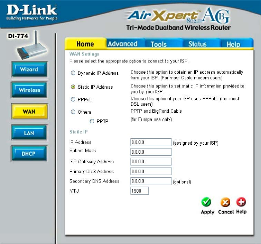
Home > WAN > Static IP Address
Static IP Address-
IP Address-
Subnet Mask-
ISP
Gateway Address-
Select this option to set static IP information provided to you
by your ISP.
Input the IP Address provided by your ISP
Input your Subnet mask. (All devices in the network must
have the same subnet mask.)
Input the Gateway address
MTU- Enter an MTU value only if required by your ISP. Otherwise,
leave this section to its default setting of 1500. (MTU is short
for Maximum Transfer Unit. Messages longer than the MTU
will be divided into smaller units for transmission).
Primary/
Secondary DNS-
Enter a DNS Address if you do not wish to use the one pro-
vided by your ISP. (DNS is short for Domain Name System. It
translates domain names into IP Addresses).
16
Using the Configuration Menu (continued)
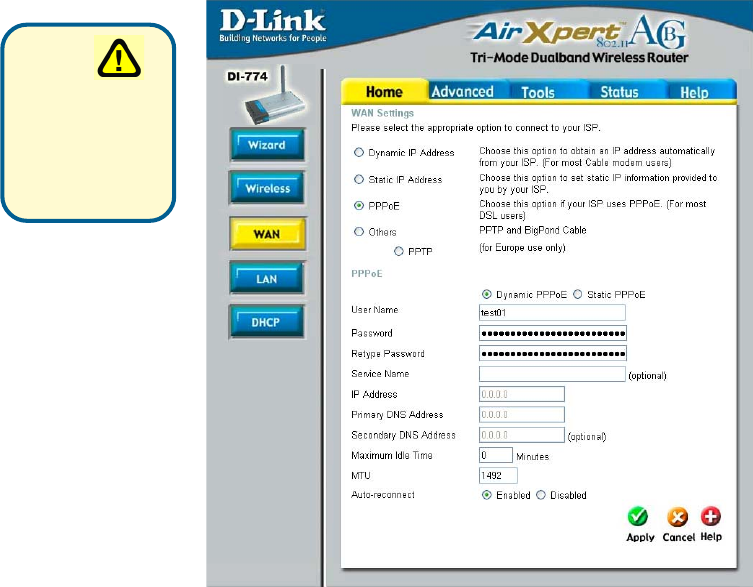
Home > WAN > PPPoE
User Name- Your PPPoE username provided by your ISP.
Password- Your PPPoE password provided by your ISP.
Retype Password- Re-enter the PPPoE password
Service Name- Enter the Service Name provided by your ISP (optional).
IP Address- This option is only available for Static PPPoE. Enter the static
IP Address for the PPPoE connection.
PPPoE- Choose this option if your ISP uses PPPoE.
(Most DSL users
will select this option).
Dynamic PPPoE- receive an IP Address automaticsally from
your ISP.
Static PPPoE- you have an assigned (static) IP Address.
Please
be sure
to remove any
existing PPPoE
client software
installed on your
computers.
17
Using the Configuration Menu (continued)
Home > WAN > PPPoE continued
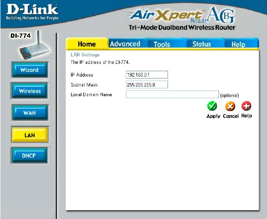
Home > LAN
LAN is short for Lo-
cal Area Network.
This is considered
your internal network.
These are the IP set-
tings of the LAN inter-
face for the DI-774.
These settings may
be referred to as Pri-
vate settings. You
may change the LAN
IP Address if needed.
The LAN IP Address
is private to your in-
ternal network and
cannot be seen on
the Internet.
Auto-reconnect- If enabled, the DI-774 will automatically connect to your ISP af-
ter your system is restarted or if the connection is dropped.
MTU- Maximum Transmission Unit-1472 is default-you may need to
change the MTU to conform with your ISP.
Subnet Mask- The subnet mask of the LAN interface.
The default subnet mask is 255.255.255.0
IP Address- The IP Address of the LAN interface. The default IP Asddress is:
192.168.0.1
Local Domain
Name- The domain name assigned to the router
Maximum
Idle Time- Enter a maximum idle time during which Internet connection is
maintained during inactivity. To disable this feature, enter zero
or enable Auto-reconnect.
Primary/Secondary
DNS-
Enter a DNS Address if you do not wish to use the one provided
by your ISP. (DNS is short for Domain Name System. It trans-
lates domain names into IP Addresses).
18
Using the Configuration Menu (continued)
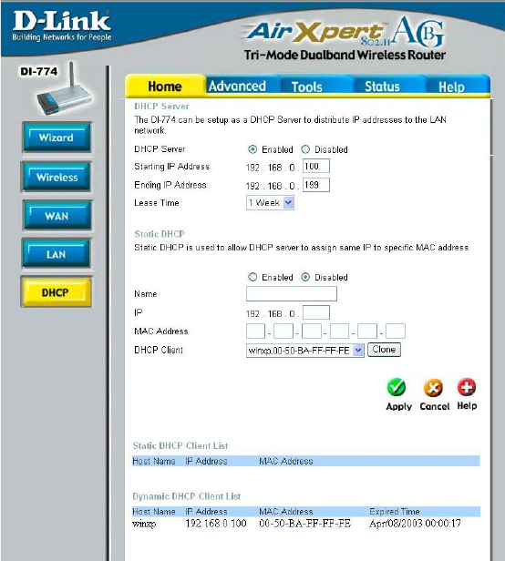
Home > DHCP
DHCP stands for
Dynamic Host
Control Protocol. The
DI-774 has a built-in
DHCP server. The
DHCP Server will
automatically assign
an IP Address to the
computers on the
LAN/private network.
Be sure to set your
computers to be
DHCP clients by
setting their TCP/IP
settings to “Obtain
an IP Address
Automatically.” When
you turn your
computers on, they
will automatically
load the proper TCP/
IP settings provided
by the DI-774. The
DHCP Server will
automatically
allocate an unused IP
Address from the IP
Address pool to the
requesting computer.
You must specify the starting and ending address of the IP Address pool.
Static & Dynamic
DHCP Client
Table- Displays a list of Static and Dynamic DHCP clients assigned by
the router
DHCP Server- Select Enabled or Disabled
Starting
IP Address- The starting IP Address for the DHCP server’s IP assignment
Ending
IP Address- The ending IP Address for the DHCP server’s IP assignment
Lease Time- The length of time of the DHCP lease
Static DHCP- Enable the Static DHCP server to assign the same IP Address
to a MAC Address that you specify here. This prevents the prob-
lems sometimes encountered with changing IP Addresses
19
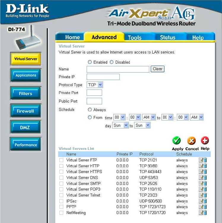
Advanced > Virtual Server
Using the Configuration Menu (continued)
The DI-774 can be configured as a virtual server so that remote users accessing Web
or FTP services via the public IP Address can be automatically redirected to local
servers in the LAN (Local Area Network).
The DI-774 firewall feature filters out unrecognized packets to protect your LAN
network so all computers networked with the DI-774 are invisible to the outside world.
If you wish, you can make some of the LAN computers accessible from the Internet
by enabling Virtual Server. Depending on the requested service, the DI-774 redirects
the external service request to the appropriate server within the LAN network.
20
Advanced > Virtual Server continued
Using the Configuration Menu (continued)
The DI-774 is also capable of port-redirection meaning incoming traffic to a particular
port may be redirected to a different port on the server computer.
Each virtual service that is created will be listed at the bottom of the screen in the
Virtual Servers List. There are pre-defined virtual services already in the table. You
may use them by enabling them and assigning the server IP to use that particular
virtual service.
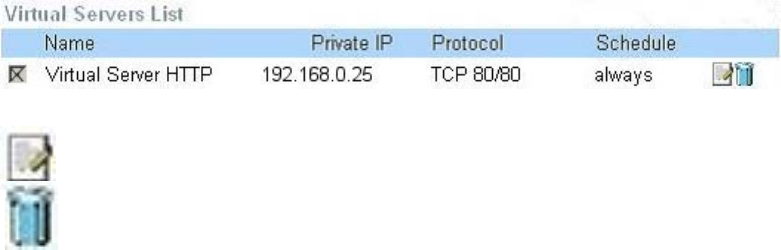
Example #1:
If you have a Web server that you wanted Internet users to access at all times, you
would need to enable it. Web (HTTP) server is on LAN (Local Area Network)
computer 192.168.0.25. HTTP uses port 80, TCP.
Name: Web Server
Private IP: 192.168.0.25
Protocol Type: TCP
Private Port: 80
Public Port: 80
Schedule: always
Protocol Type- The protocol used for the virtual service
Public Port- The port number on the WAN (Wide Area Network)side that will
be used to access the virtual service.
Private Port- The port number of the service used by the Private IP computer
Schedule-The schedule of time when the virtual service will be enabled.
The schedule may be set to Always, which will allow the
particular service to always be enabled. If it is set to Time,
select the time frame for the service to be enabled. If the
system time is outside of the scheduled time, the service will
be disabled.
Virtual Server- Select Enabled or Disabled
Name- Enter the name referencing the virtual service
Private IP- The server computer in the LAN (Local Area Network) that will be
providing the virtual services.
21
Example #2:
If you have an FTP server that you wanted Internet users to access by WAN port
2100 and only during the weekends, you would need to enable it as such. FTP
server is on LAN computer 192.168.0.30. FTP uses port 21, TCP.
Name: FTP Server
Private IP: 192.168.0.30
Protocol Type: TCP
Private Port: 21
Public Port: 2100
Schedule: From: 01:00AM to 11:00PM, Sat to Sun
Using the Configuration Menu (continued)
Advanced > Virtual Server continued
Click on this icon to edit the virtual service
Click on this icon to delete the virtual service
All Internet users who want to access this FTP Server
must connect to it from port 2100. This is an example of
port redirection and can be useful in cases where there
are many of the same servers on the LAN network.
22
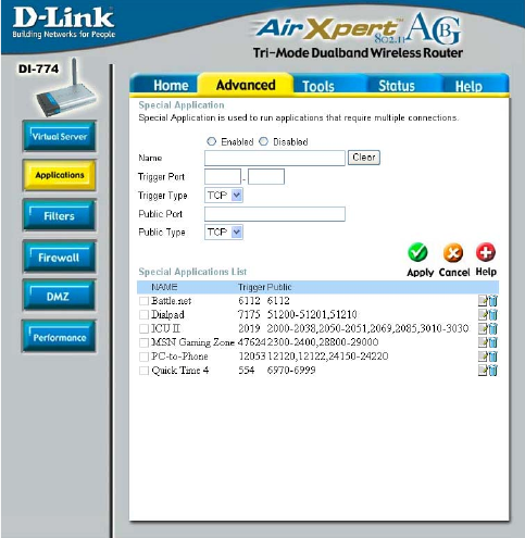
Using the Configuration Menu (continued)
Advanced > Applications
Some applications require multiple connections, such as Internet gaming, video
conferencing, Internet telephony and others. These applications have difficulties
working through NAT (Network Address Translation). Special Applications makes
some of these applications work with the DI-774. If you need to run applications that
require multiple connections, specify the port normally associated with an application
in the “Trigger Port” field, select the protocol type as TCP or UDP, then enter the
public ports associated with the trigger port to open them for inbound traffic.
The DI-774 provides some predefined applications in the table on the bottom of the
web page. Select the application you want to use and enable it.
Note! Only one PC can use each Special Application tunnel.
Name: This is the name referencing the special application.
Trigger Port: This is the port used to trigger the application. It can be either
a single port or a range of ports.
Trigger Type: This is the protocol used to trigger the special application.
Public Port: This is the port number on the WAN side that will be used to
access the application. You may define a single port or a
range of ports. You can use a comma to add multiple ports or
port ranges.
Public Type: This is the protocol used for the special application.
23
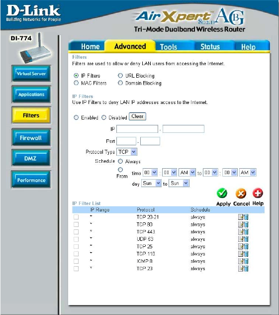
Using the Configuration Menu (continued)
Advanced > Filters > IP Filters
Filters are used to deny or allow LAN (Local Area Network) computers from accessing
the Internet. The DI-774 can be setup to deny internal computers by their IP or MAC
addresses. The DI-774 can also block users from accessing restricted web sites.
This is the schedule of time when the IP Filter will be enabled.
Schedule-
Select the protocol type
Protocol Types-
The single port or port range that will be denied access to the
Internet.
Port-
Use IP Filters to deny LAN IP Addresses from accessing the
Internet. You can deny specific port numbers or all ports for
the specific IP Address.
IP Filters-
The IP Address of the LAN computer that will be denied
access to the Internet.
IP-
24
Using the Configuration Menu
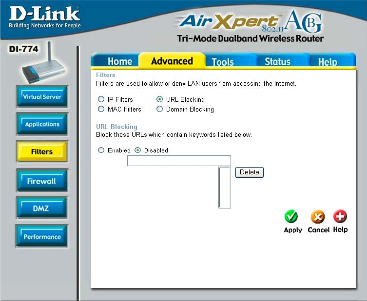
Advanced > Filters > URL Blocking
Filters-
URL Blocking is used to deny LAN computers from accessing specific web sites. A
URL is a specially formatted text string that defines a location on the Internet. If any
part of the URL contains the blocked word, the site will not be accessible and the web
page will not display.
Select the filter you wish to use; in this case, URL Blocking
was chosen.
Keywords- Block URLs which contain the keywords listed below.
Enter the keywords in this space.
URL Blocking- Select Enabled or Disabled.
25
Using the Configuration Menu
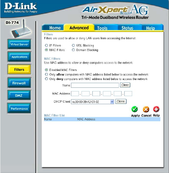
Advanced > Filters > MAC Filters
Use MAC (Media Access Control) Filters to allow or deny LAN (Local Area Network)
computers by their MAC addresses from accessing the Internet. You can either
manually add a MAC address or select the MAC address from the list of clients that
are currently connected to the Broadband Router.
MAC Filters- Choose to Disable MAC filters, or choose to allow or deny
MAC addresses listed below.
Filters- Select the filter you wish to use; in this case, MAC filters was
chosen.
Name- Enter the name here.
MAC Address- Enter the MAC Address of the client that will be allowed or de-
nied access.
DHCP Client- Select a DHCP client from the pull-down list; click Clone to
copy that MAC Address.
26
Using the Configuration Menu (continued)
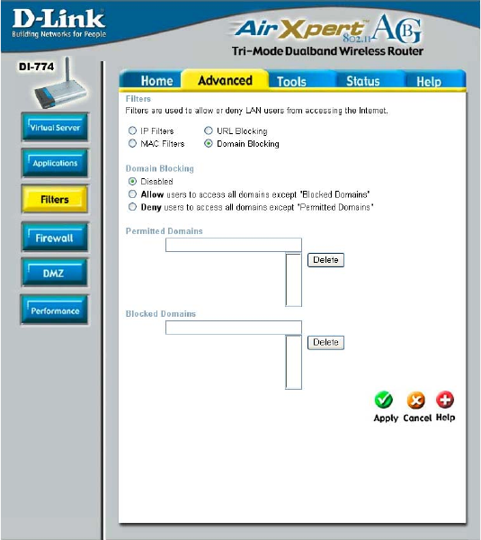
Advanced > Filters > Domain Blocking
Domain Blocking is used to allow or deny LAN (Local Area Network) computers from
accessing specific domains on the Internet. Domain blocking will deny all requests to a
specific domain such as http and ftp. It can also allow computers to access specific
sites and deny all other sites.
Filters-
Domain Blocking
Blocked Domains-
Permitted
Domains-
Select the filter you wish to use; in this case, Domain Blocking
was chosen.
Disabled-
Allow-
Deny-
Enter the Permitted Domains in this field
Enter the Blocked Domains in this field
Select Disabled to disable Domain Blocking
Allows users to access all domains except Blocked Domains
Denies users access to all domains except Permitted Domains
27
Using the Configuration Menu (continued)
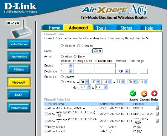
Advanced > Firewall
Firewall Rules is an advanced feature used to deny or allow traffic from passing
through the DI-774. It works in the same way as IP Filters with additional settings.
You can create more detailed access rules for the DI-774. When virtual services are
created and enabled, it will also display in Firewall Rules. Firewall Rules contains all
network firewall rules pertaining to IP (Internet Protocol).
In the Firewall Rules List at the bottom of the screen, the priorities of the rules are
from top (highest priority) to bottom (lowest priority.)
Note: The DI-774 MAC Address filtering rules have precedence over the Firewall
Rules.
Schedule- Select Always or enter the Time.
Firewall Rules-
Name-
Action-
Source-
Enable or disable the Firewall Rules
Enter a name for the rule
Allow or deny IP traffic through the router
Enter the IP Address range
Destination- Enter the IP Address range; the Protocol;
and the Port Range
28
Advanced > DMZ
Using the Configuration Menu (continued)
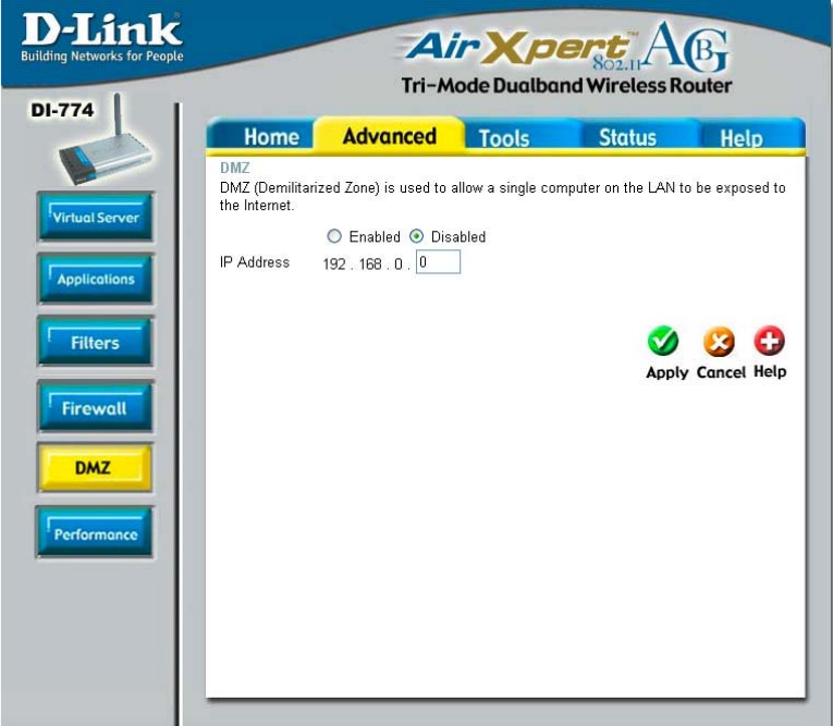
If you have a client PC that cannot run Internet applications properly from behind the
DI-774, then you can set the client up to unrestricted Internet access. It allows a
computer to be exposed to the Internet. This feature is useful for gaming purposes.
Enter the IP Address of the internal computer that will be the DMZ host. Adding a
client to the DMZ (Demilitarized Zone) may expose your local network to a variety of
security risks, so only use this option as a last resort.
DMZ-
IP Address-
Enable or disable the DMZ. The DMZ (Demilitarized Zone)
allows a single computer to be exposed to the Internet.
Enter the IP Address of the computer to be in the DMZ
29
Using the Configuration Menu (continued)
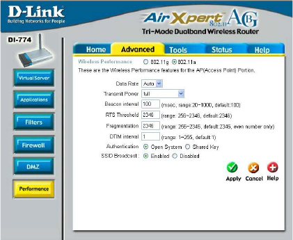
Advanced > Performance > 802.11a
DTIM interval- (Delivery Traffic Indication Message) 1 is the default setting. A
DTIM is a countdown informing clients of the next window for
listening to broadcast and multicast messages.
RTS Threshold- This value should remain at its default setting of 2346. If incon-
sistent data flow is a problem, only a minor modification should
be made.
Beacon interval- Beacons are packets sent by the DI-774 to synchronize a wire-
less network. Specify a value. 100 is the default setting and is
recommended.
Data Rate-
Auto is the default se-
lection. Select from the
drop down menu for
your selection.
Wireless
Performance-
Select 802.11a or
802.11g. Here,
802.11a has been
chosen. This screen
displays the wireless
performance features
of the Access Point
portion of the DI-774.
Fragmentation- This value should also remain at its default setting of 2346. If you
experience a high packet error rate, you may slightly increase
your Fragmentation value within the range of 256-2346. Setting
the Fragmentation value too low may result in poor performance.
Authentication- Select Open system or Shared Key
Open System - The DI-774 will be visible to all devices on the network. This is
the default setting
Shared Key - In this mode, in order to access the DI-774 on the network, the
device must be listed in the MAC Address Control List
Transmit Power- Full is the default selection. Select from the drop down menu for
your selection.
SSID Broadcast- Choose Enabled to broadcast the SSID across the network.
All devices on a network must share the same SSID (Service
Set Identifier) to establish communication. Choose Disabled
if you do not wish to broadcast the SSID over the network.
30
Using the Configuration Menu (continued)
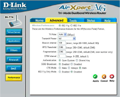
Advanced > Performance > 802.11g
Wireless
Performance-
Select 802.11a or
802.11g. 802.11g is
selected here. Dis-
played in this window
are the Wireless Per-
formance features for
the Access Point por-
tion of the DI-774.
TX Rates-
Auto is the default
selection. Select
from the drop down
menu for your selection.
Full is the default selection. Select from the drop down menu for
your selection.
Transmit Power-
RTS Threshold- This value should remain at its default setting of 2346. If incon-
sistent data flow is a problem, only a minor modification should
be made.
Fragmentation- This value should also remain at its default setting of 2346. If you
experience a high packet error rate, you may slightly increase
your Fragmentation value within the range of 256-2346. Setting
the Fragmentation value too low may result in poor performance.
DTIM interval- (Delivery Traffic Indication Message) 1 is the default setting. A
DTIM is a countdown informing clients of the next window for
listening to broadcast and multicast messages.
Beacon interval- Beacons are packets sent by the DI-774 to synchronize a wire-
less network. Specify a value. 100 is the default setting and is
recommended.
Shared Key - In this mode, in order to access the DI-774 on the network, the
device must be listed in the MAC Address Control List
Open System - The DI-774 will be visible to all devices on the network. This is
the default setting
Select Open system or Shared KeyAuthentication-
SSID Broadcast- Choose Enabled to broadcast the SSID across the network.
All devices on a network must share the same SSID (Service
Set Identifier) to establish communication. Choose Disabled
if you do not wish to broadcast the SSID over the network.