D Link DI824VUPB1 Wireless VPN Router User Manual 0115 di 824VUP pmd
D Link Corporation Wireless VPN Router 0115 di 824VUP pmd
UserManual.wiki
>
D Link
>
DI824VUPB1 User Manual
>
User Manual Part 1
Contents
1.
User Manual Part 1
2.
User Manual Part 2
3.
USer Manual Part 3
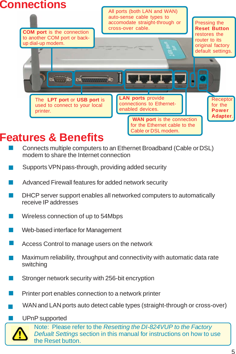
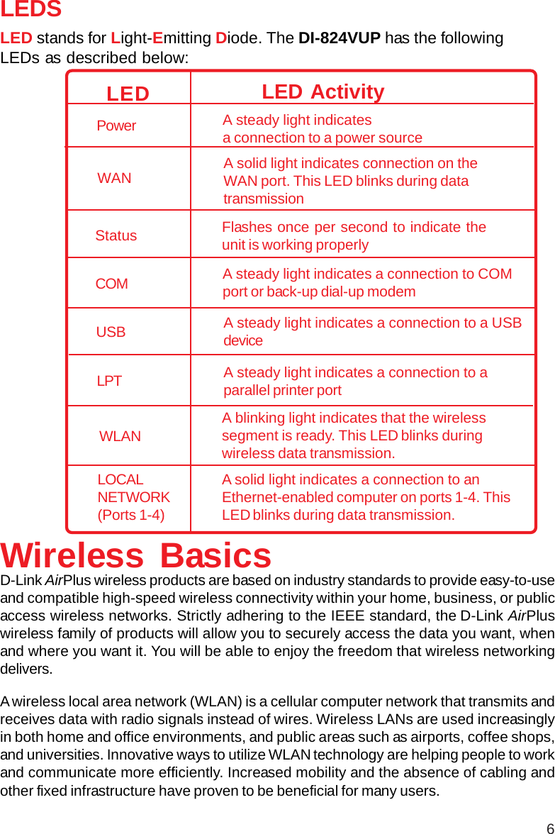
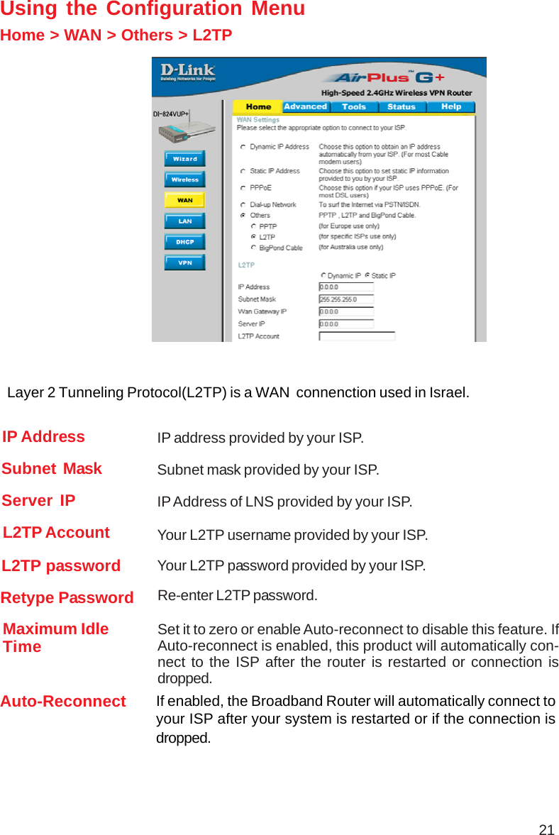
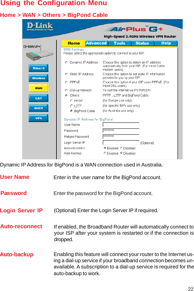
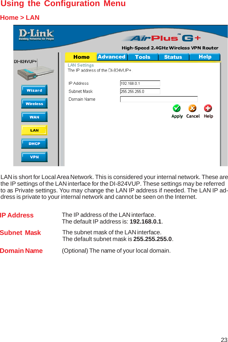
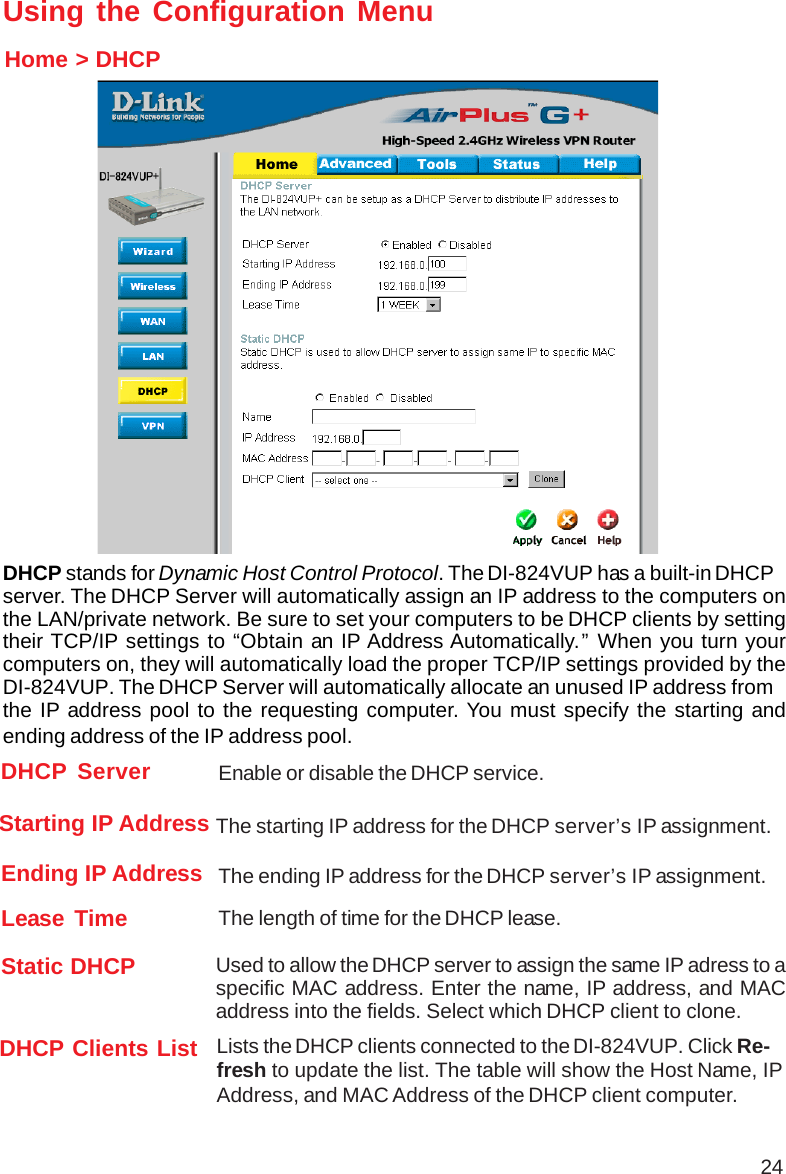
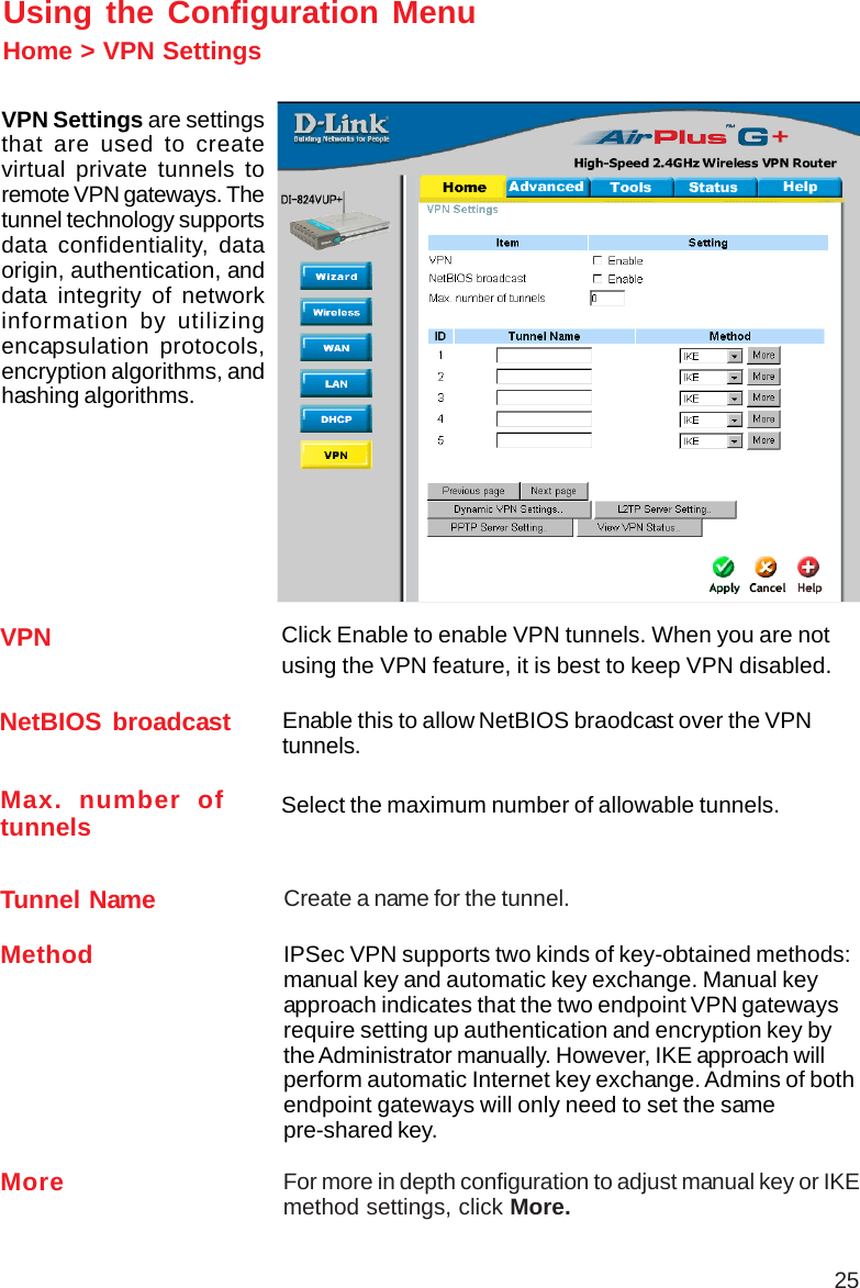
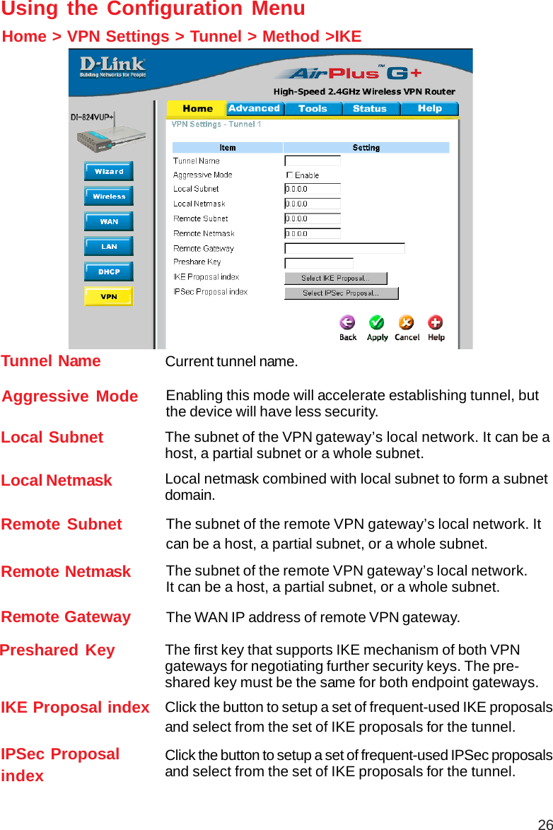
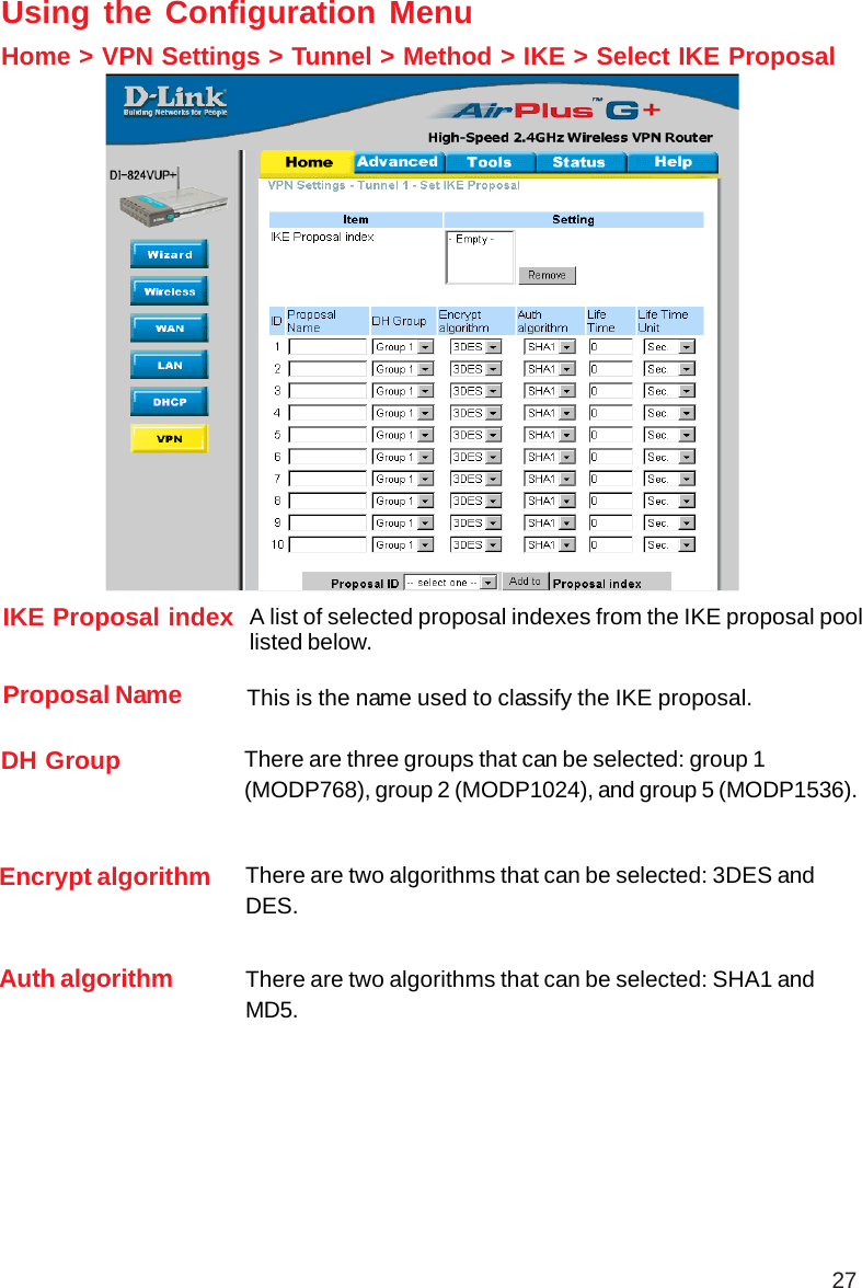
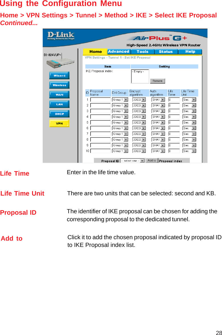
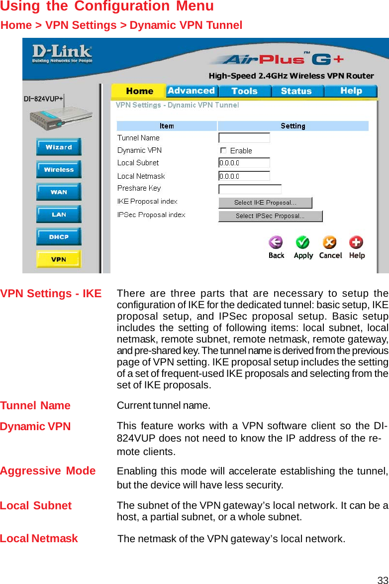
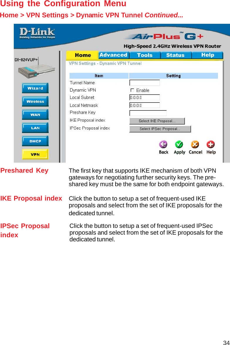
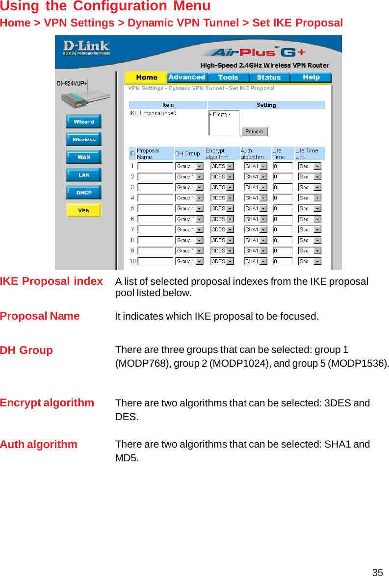
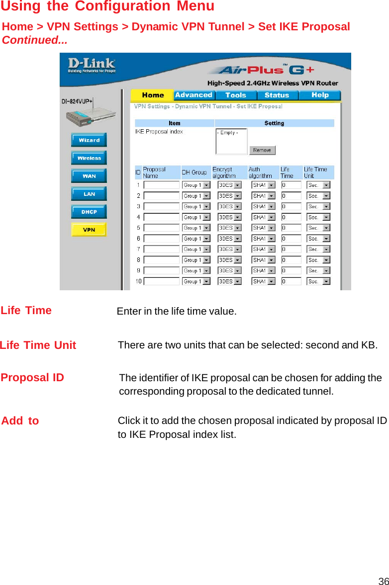
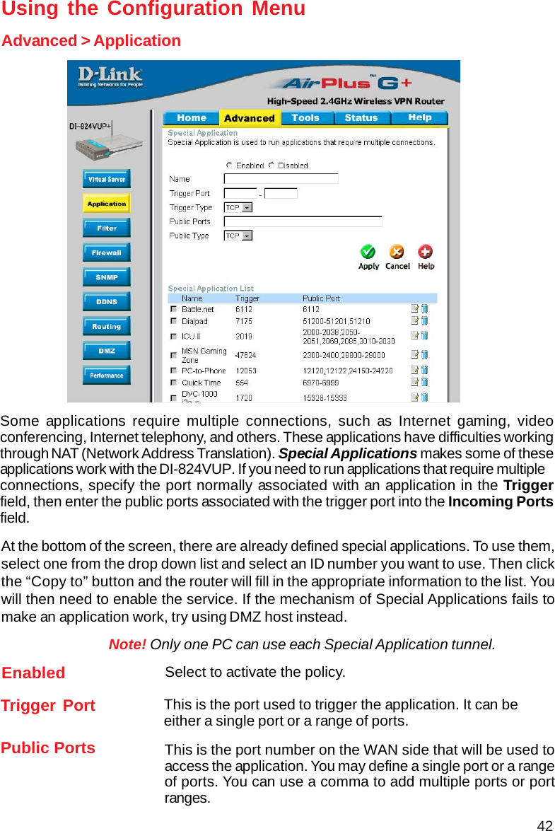
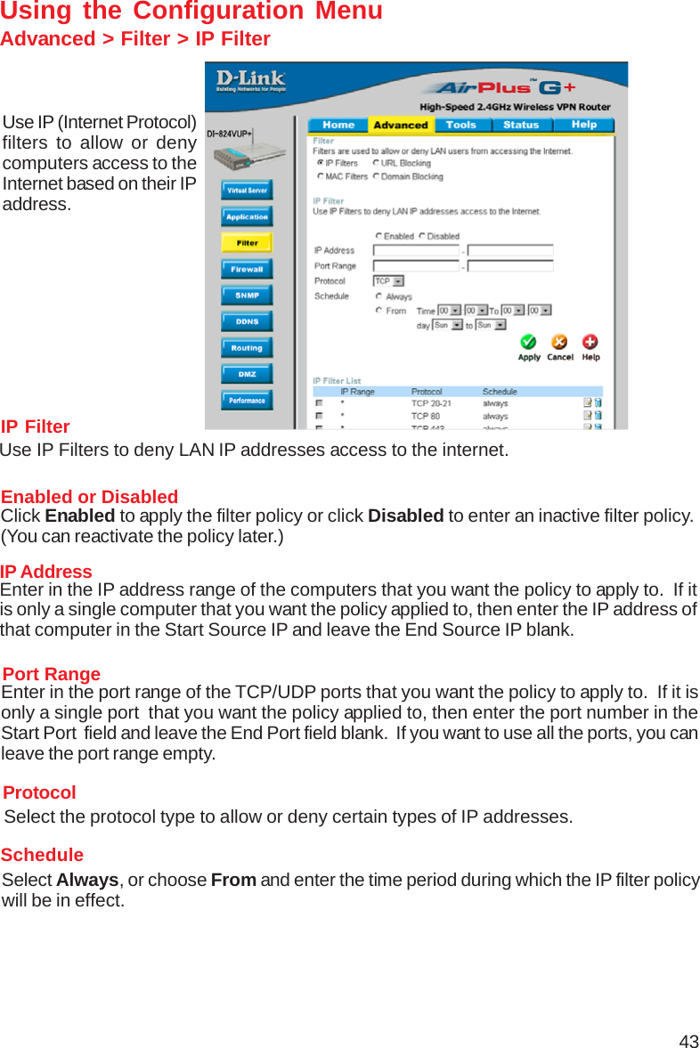
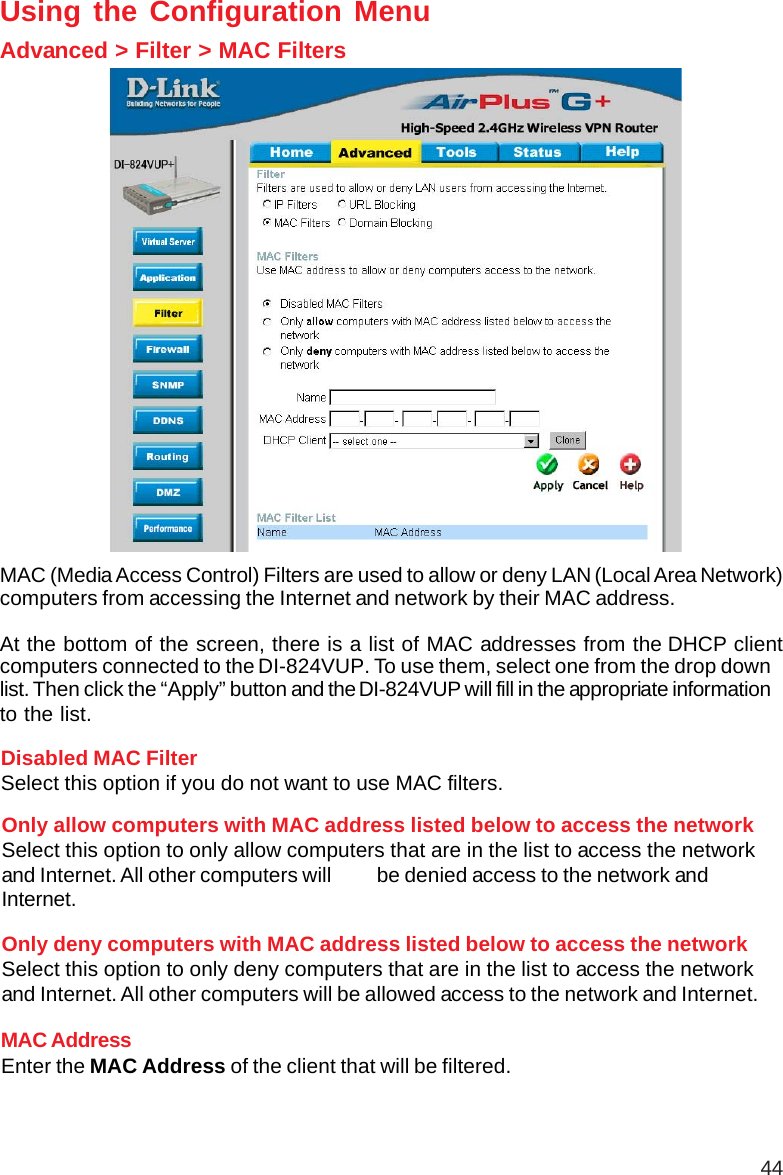
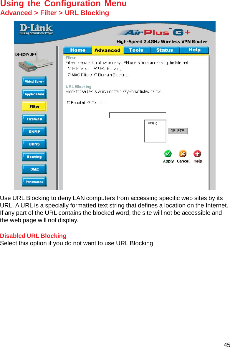
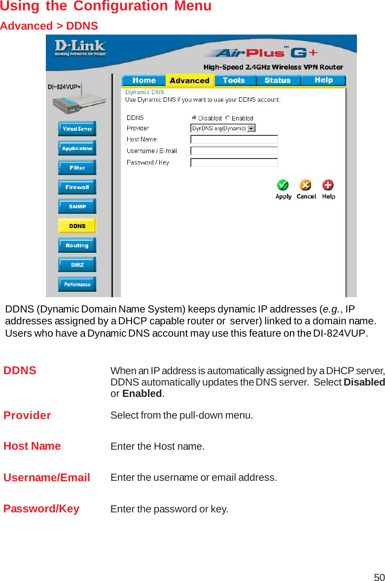
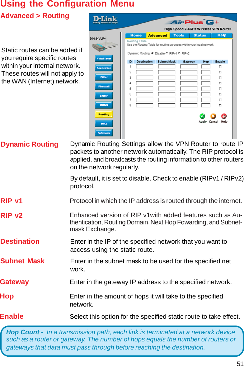
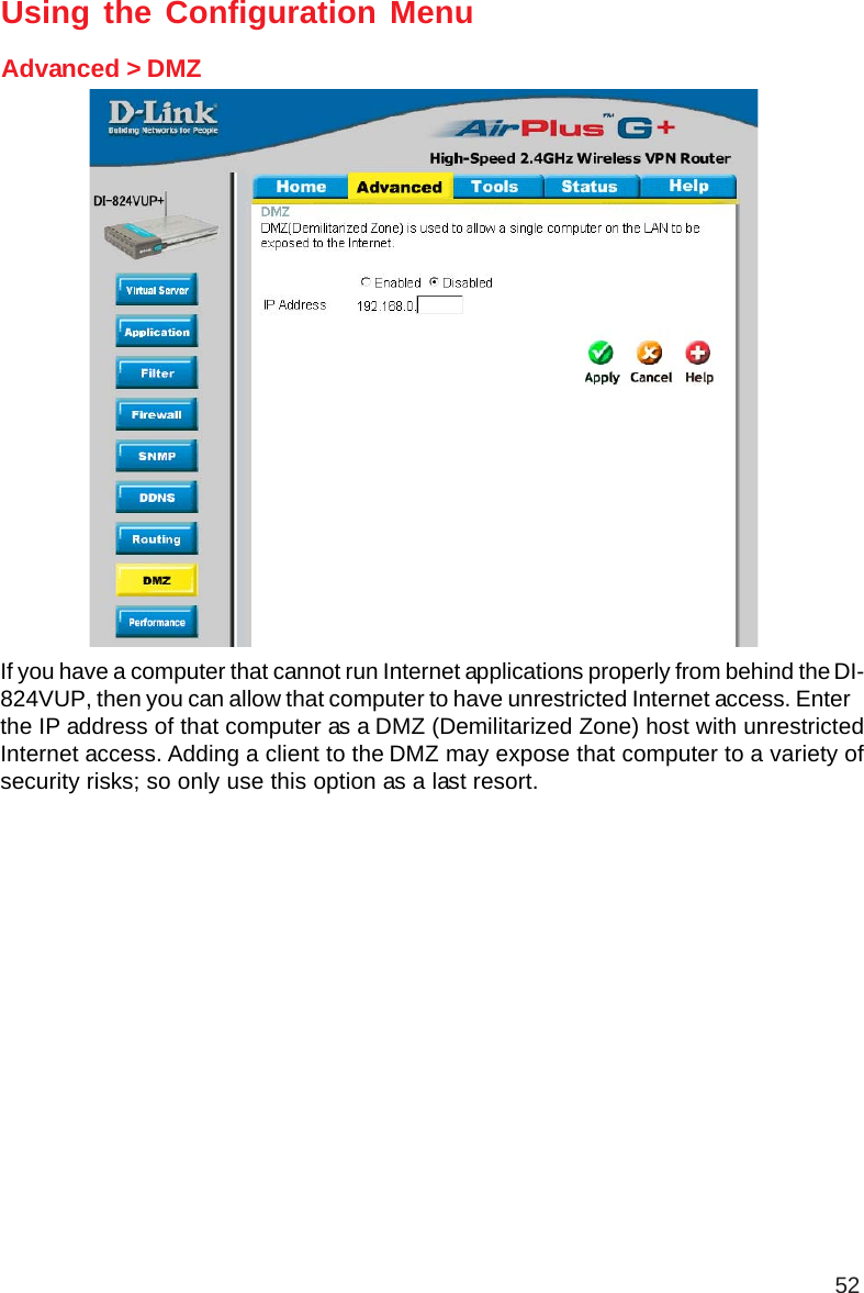
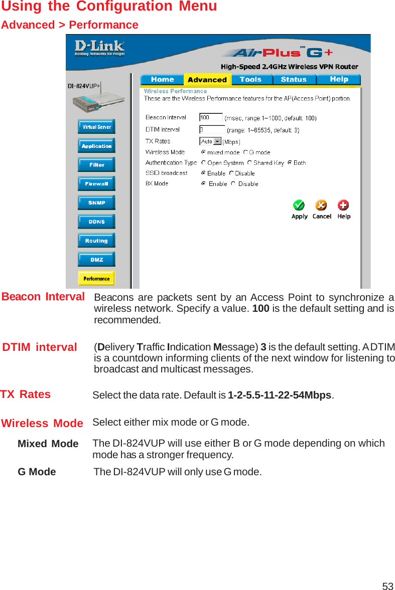
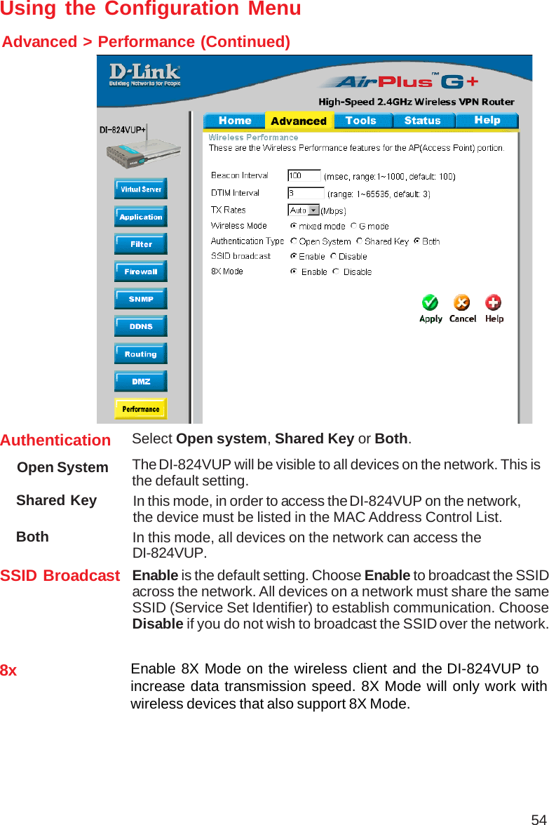
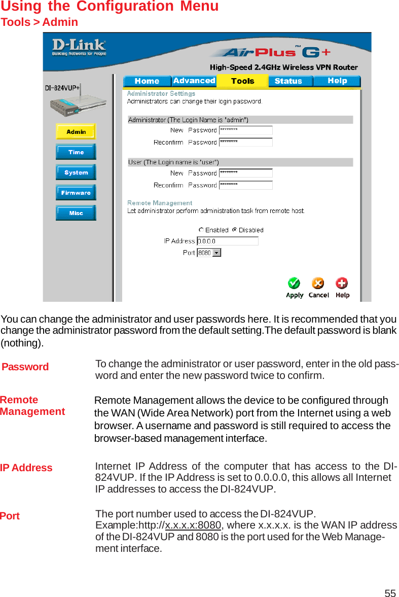
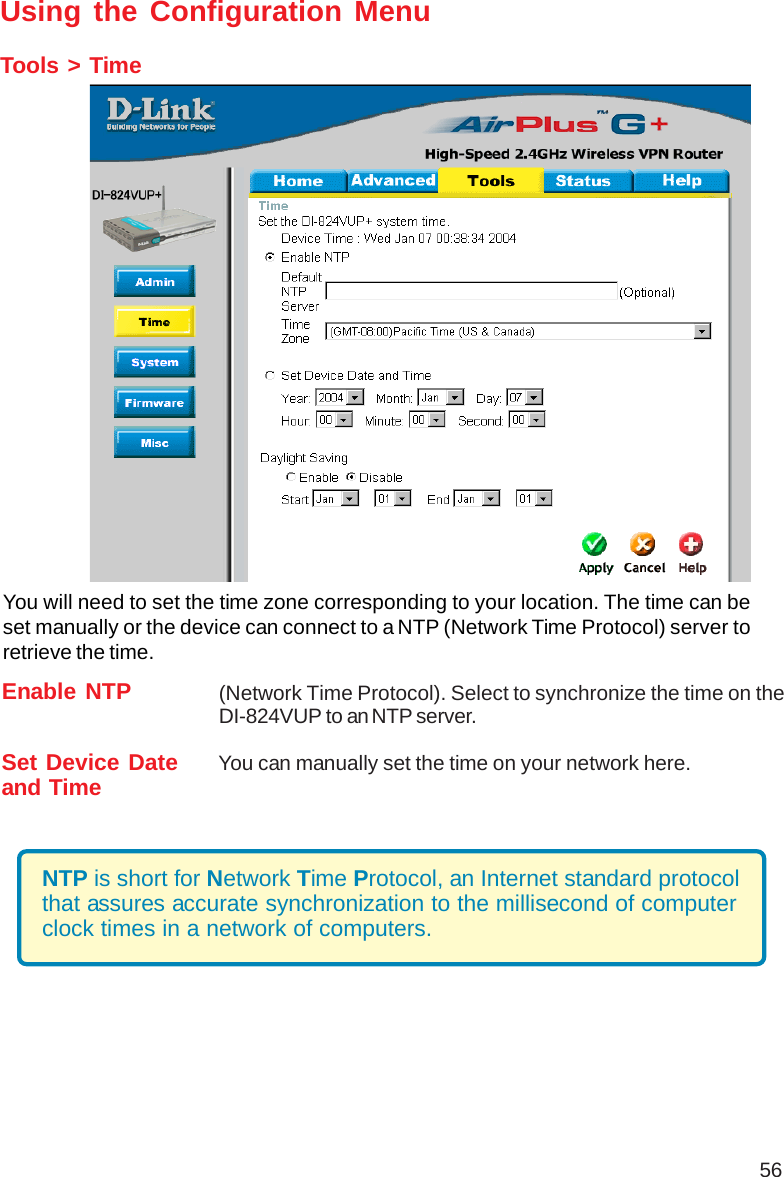
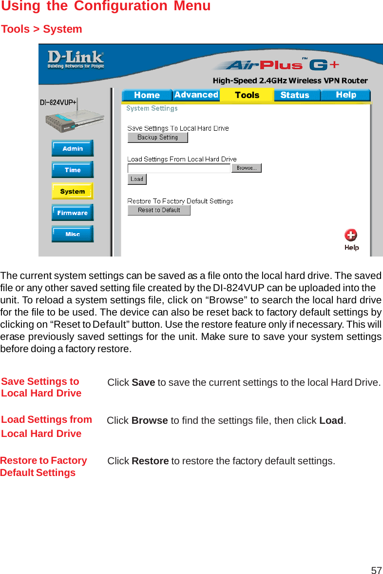
User Manual Part 1
Navigation menu
Upload a User Manual
Namespaces
Wiki Guide
HTML
PDF
Info
Views
User Manual
Discussion / Help
Navigation