D Link DI824VUPB1 Wireless VPN Router User Manual 0115 di 824VUP pmd
D Link Corporation Wireless VPN Router 0115 di 824VUP pmd
D Link >
Contents
- 1. User Manual Part 1
- 2. User Manual Part 2
- 3. USer Manual Part 3
User Manual Part 1

High-Speed Enhanced 2.4 GHz
Manual
Wireless VPN Router
Building Networks for People
1/19/2004
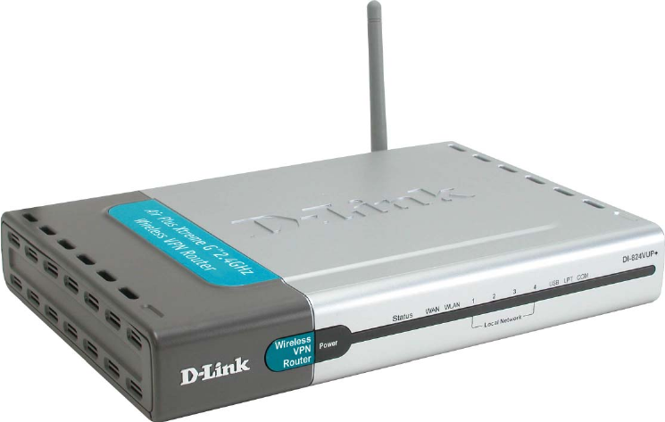
DI-824VUP
D-Link AirPlus G+
2
Contents
Package Contents.................................................................................3
Introduction............................................................................................4
Wireless Basics ....................................................................................6
Getting Started......................................................................................9
Using the Configuration Menu..............................................................11
Networking Basics ..............................................................................72
Reset to Factory Default Settings.......................................................101
Technical Specifications ....................................................................102
Frequently Asked Questions ..............................................................103
Contacting Technical Support ............................................................152
Warranty and Registration..................................................................153
Installing the Print Server Software ......................................................68
Configuring on Windows 98se/Me Platforms .......................................70
3
Contents of Package:
D-Link AirPlus G+ DI-824VUP High-Speed Enhanced
2.4GHz Wireless VPN Router
Power Adapter - 5V DC / 2.5A
Manual on CD
Quick Installation Guide
Package Contents
Note: Using a power supply with a different voltage rating than the one included with the
DI-824VUP will cause damage and void the warranty for this product.
If any of the above items are missing, please contact your reseller.
System Requirements For Configuration:
Computer with Windows, Macintosh, or Linux-based
operating system with an installed Ethernet adapter
Internet Explorer version 6.0 or Netscape Navigator
version 6.0 and above, with JavaScript enabled
Ethernet-Based Cable or DSL Modem
4
Introduction
The D-Link AirPlus G+ DI-824VUP Wireless Broadband Router is an enhanced
802.11b high-performance, wireless router with a printer port. It is an ideal way
to extend the reach and number of computers connected to your wireless
network.
Unlike most 802.11g routers, the DI-824VUP is capable of data transfer speeds
up to 54 Mbps (compared to the standard 11 Mbps) when used with other D-
Link AirPlus Xtreme G products such as the DWL-G650 and DWL-G520 Wireless
Adapters.
After completing the steps outlined in the Quick Installation Guide (included in
your package) you will have the ability to share information and resources, as
well as share a printer wirelessly on your network.
The DI-824VUP is compatible with most popular operating systems, including
Macintosh, Linux and Windows, and can be integrated into a large network.
This Manual is designed to help you connect the Router and D-Link AirPlus
2.4GHz Wireless Adapters into a network in Infrastructure mode. Please take a
look at the Getting Started section in this manual to see an example of an
Infrastructure network using the DI-824VUP.
5
Connections
DHCP server support enables all networked computers to automatically
receive IP addresses
Wireless connection of up to 54Mbps
Web-based interface for Management
Access Control to manage users on the network
Maximum reliability, throughput and connectivity with automatic data rate
switching
Stronger network security with 256-bit encryption
Printer port enables connection to a network printer
Connects multiple computers to an Ethernet Broadband (Cable or DSL)
modem to share the Internet connection
Supports VPN pass-through, providing added security
Advanced Firewall features for added network security
Features & Benefits
Note: Please refer to the Resetting the DI-824VUP to the Factory
Defualt Settings section in this manual for instructions on how to use
the Reset button.
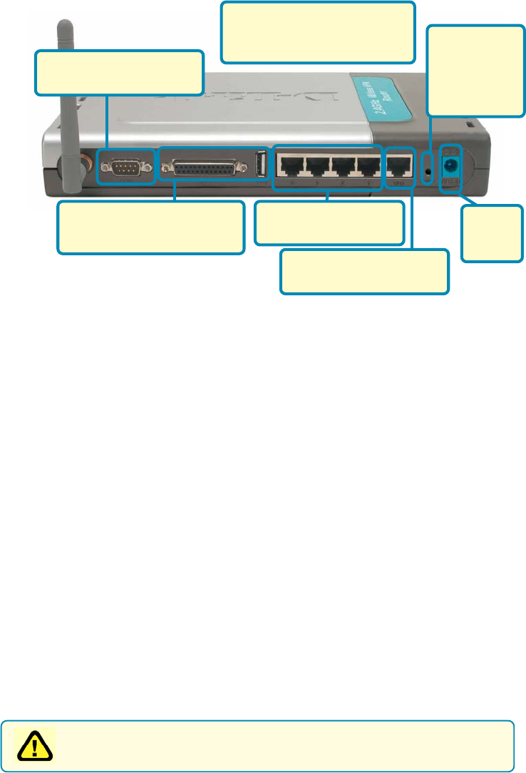
WAN and LAN ports auto detect cable types (straight-through or cross-over)
UPnP supported
LAN ports provide
connections to Ethernet-
enabled devices.
Pressing the
Reset Button
restores the
router to its
original factory
default settings.
All ports (both LAN and WAN)
auto-sense cable types to
accomodate straight-through or
cross-over cable.
Receptor
for the
Power
Adapter.
WAN port is the connection
for the Ethernet cable to the
Cable or DSL modem.
COM port is the connection
to another COM port or back-
up dial-up modem.
The LPT port or USB port is
used to connect to your local
printer.

6
LEDS
LED stands for Light-Emitting Diode. The DI-824VUP has the following
LEDs as described below:
LED LED Activity
Power A steady light indicates
a connection to a power source
WAN A solid light indicates connection on the
WAN port. This LED blinks during data
transmission
WLAN
A blinking light indicates that the wireless
segment is ready. This LED blinks during
wireless data transmission.
D-Link AirPlus wireless products are based on industry standards to provide easy-to-use
and compatible high-speed wireless connectivity within your home, business, or public
access wireless networks. Strictly adhering to the IEEE standard, the D-Link AirPlus
wireless family of products will allow you to securely access the data you want, when
and where you want it. You will be able to enjoy the freedom that wireless networking
delivers.
A wireless local area network (WLAN) is a cellular computer network that transmits and
receives data with radio signals instead of wires. Wireless LANs are used increasingly
in both home and office environments, and public areas such as airports, coffee shops,
and universities. Innovative ways to utilize WLAN technology are helping people to work
and communicate more efficiently. Increased mobility and the absence of cabling and
other fixed infrastructure have proven to be beneficial for many users.
Wireless Basics
Flashes once per second to indicate the
unit is working properly
LOCAL
NETWORK
(Ports 1-4)
A solid light indicates a connection to an
Ethernet-enabled computer on ports 1-4. This
LED blinks during data transmission.
Status
USB
COM
A steady light indicates a connection to a USB
device
A steady light indicates a connection to COM
port or back-up dial-up modem
LPT A steady light indicates a connection to a
parallel printer port
7
Wireless Basics
Wireless users can use the same applications they use on a wired network.
Wireless adapter cards used on laptop and desktop systems support the same
protocols as Ethernet adapter cards.
Under many circumstances, it may be desirable for mobile network devices to
link to a conventional Ethernet LAN in order to use servers, printers, or an Internet
connection supplied through the wired LAN. A Wireless Router is a device used
to provide this link.
People use wireless LAN technology for many different purposes:
Mobility - Productivity increases when people have access to data in any
location within the operating range of the WLAN. Management decisions based
on real-time information can significantly improve worker efficiency.
Low Implementation Costs - WLANs (Wireless Local Area Networks) are
easy to set up, manage, change, and relocate. Networks that frequently change,
both physically and logically, can benefit from WLANs ease of implementation.
WLANs can operate in locations where installation of wiring may be impractical.
Installation Speed and Simplicity - Installing a wireless LAN system can
be fast, easy, and can eliminate the need to pull cable through walls and ceilings.
Network Expansion - Wireless technology allows the network to go where
wires cannot.
Scalability - Wireless Local Area Networks (WLANs) can be configured in a
variety of topologies to meet the needs of specific applications or existing
infrastructure. Configurations are easily changed and range from peer-to-peer
networks suitable for a small number of users to larger infrastructure networks
to accommodate hundreds or thousands of users, depending on the number of
wireless devices deployed.
8
Wireless Basics
The DI-824VUP is compatible with other D-Link AirPlus Xtreme G 802.11g
products, which include:
♦Enhanced 2.4GHz Wireless Cardbus Adapters used with laptop
computers (DWL-G650)
♦Enhanced 2.4GHz Wireless PCI cards used with desktop computers
(DWL-G520)
Installation Considerations
The D-Link AirPlus G+ DI-824VUP lets you access your network, using a
wireless connection, from virtually anywhere. Keep in mind, however, that the
number, thickness, and location of walls, ceilings, or other objects that the
wireless signals must pass through may limit the range. Typical ranges vary
depending on the types of materials and background RF (radio frequency) noise
in your home or business. The key to maximizing wireless range is to follow
these basic guidelines:
1. Keep the number of walls and ceilings between the DI-824VUP and
your receiving device (e.g., the DWL-G650) to a minimum-each wall or
ceiling can reduce your D-Link AirPlus wireless product’s range from 3-90
feet (1-30 meters.) Position your receiving devices so that the number of
walls or ceilings is minimized.
2. Be aware of the direct line between routers and computers. A wall that is
1.5 feet thick (.5 meters), at a 45-degree angle appears to be almost 3 feet
(1 meter) thick. At a 2-degree angle it looks over 42 feet (14 meters) thick!
Try to make sure that devices are positioned so that the signal will travel
straight through a wall or ceiling for better reception.
3. Building Materials make a difference - a solid metal door or aluminum
studs may have a negative effect on range. Try to position wireless
devices and computers with wireless adapters so that the signal passes
through drywall or open doorways and not other materials.
4. Keep your product away (at least 3-6 feet or 1-2 meters) from electrical
devices or appliances that generate RF noise.
Based on the IEEE 802.11g standard, the DI-824VUP is interoperable with
existing compatible 2.4GHz wireless technology with data transfer speeds of
up to 54Mbps (with the D-Link AirPlus family of wireless devices,) as well as
standard 802.11b technology ( the D-Link Air family of wireless devices), with
speeds of up to 11Mbps.
Standards-Based Technology

9
With a single IP Address from your Broadband Internet Service provider you
can share the Internet with all the computers on your local network, without
sacrificing speed or security, using D-Link Air networking products.
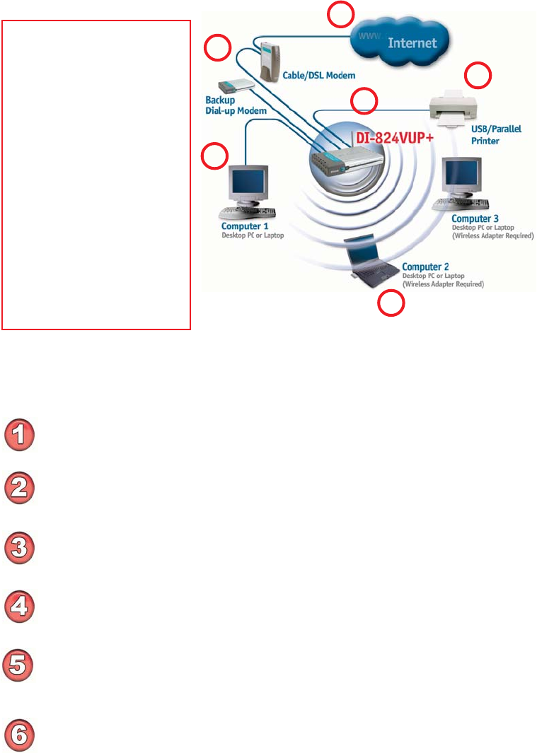
Getting Started
An Infrastructure wireless network contains an Access Point. The
Infrastructure Network example, shown here, contains the following D-Link
network devices:
A wireless Broadband Router -
D-Link AirPlus G+ DI-824VUP
A laptop computer with a wireless adapter -
D-Link AirPlus Xtreme G DWL-G650
A desktop computer with a wireless adapter -
D-Link AirPlus Xtreme G DWL-G520
A Cable modem -
D-Link DCM-201
If you need to assign IP Addresses to the computers on the network, please
remember that the IP Address for each computer must be in the same
IP Address range as all the computers in the network, and the Subnet
Mask must be exactly the same for all the computers in the network.
For example: If the first computer is assigned an IP Address of 192.168.0.2
with a Subnet Mask of 255.255.255.0, then the second computer can be
assigned an IP Address of 192.168.0.3 with a Subnet Mask of 255.255.255.0,
etc.
IMPORTANT: If computers or other devices are assigned the same IP
Address, one or more of the devices may not function properly on
the network.
IP ADDRESS
With its default settings, the DI-824VUP will connect with
other D-Link Air or AirPlus products, right out of the box.
Note: If you are using a DHCP-capable router in your network setup, such
as the DI-824VUP, you will not need to assign a static IP Address.
10
Please remember that D-Link AirPlus wireless devices are pre-configured to connect
together, right out of the box, with their default settings.
Getting Started
Please refer to the following
sections of this manual for
additional information about
setting up a network:
Networking Basics - learn
how to check and assign
your IP Address; share
printers and files.
Using the Configuration
Menu - learn the settings for
the DI-824VUP, using the
web-based interface.
Troubleshooting - learn
how to check for common
installation issues and other
tips for troubleshooting.
For a typical wireless setup at home (as shown above), please do the
following:
You will need broadband Internet access (a Cable or DSL subscription line into
your home or office).
Consult with your Cable or DSL provider for proper installation of the modem.
Connect the Cable or DSL modem to the DI-824VUP wireless broadband router
(See the Quick Installation Guide included with the DI-824VUP.)
If you are connecting a desktop computer to your network, you can install the
D-Link AirPlus Xtreme G DWL-G520 wireless PCI adapter into an available PCI
slot. (See the Quick Installation Guide included with the DWL-G520.)
If you are connecting a laptop computer to your network, install the drivers for
the wireless cardbus adapter (e.g., D-Link AirPlus Xtreme G DWL-G650) into a
laptop computer.(See the Quick Installation Guide included with the DWL-G650.)
(See the Quick Installation Guide included with the DWL-650+.)
Connect your printer to the printer port on the DI-824VUP. Please refer to
the quick installation guide for loading the print server software.
4
5
6
3
1
2
11
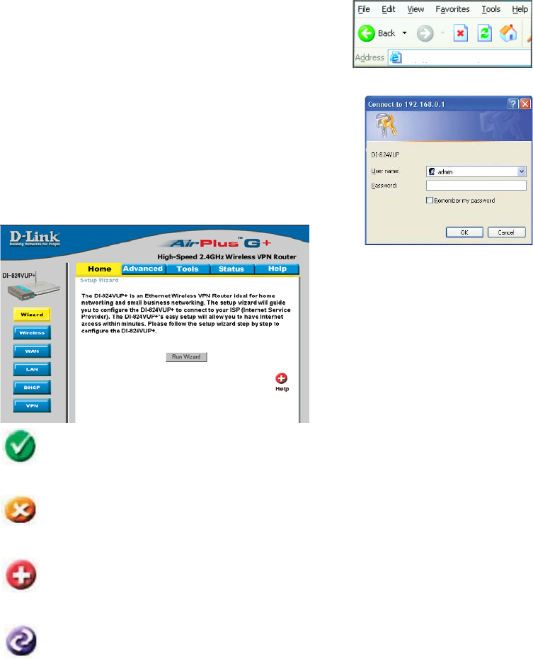
Using the Configuration Menu
Whenever you want to configure your network or the DI-824VUP, you can access the
Configuration Menu by opening the web-browser and typing in the IP Address of the
DI-824VUP. The DI-824VUP default IP Address is shown below:
Open the web browser
Type in the IP Address of
the DI-824VUP
Home > Wizard
The Home>Wizard screen will
appear. Please refer to the
Quick Installation Guide for
more information regarding the
Setup Wizard.
http://192.168.0.1
Note: if you have changed the default IP Address assigned to the DI-824VUP, make sure
to enter the correct IP Address.
The factory default User name is admin and the default
Password is blank (empty). It is recommended that you
change the admin password for security purposes. Please
refer to Tools > Admin to change the admin password.
Clicking Apply will save changes made to the page.
Apply
Clicking Cancel will clear changes made to the page.
Clicking Help will bring up helpful information regarding the page.
Help
Clicking Restart will restart the router. (Necessary for some changes.)
Cancel
Restart
+
12
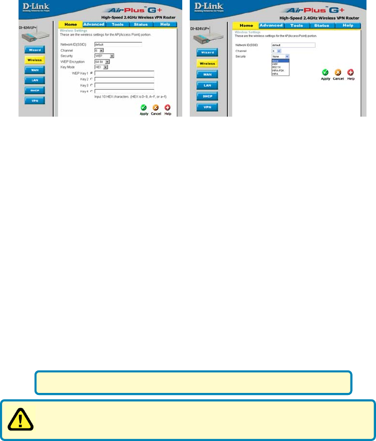
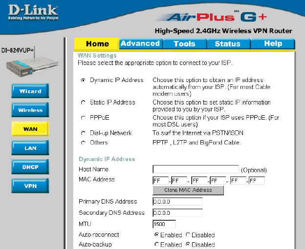
Home > Wireless
Using the Configuration Menu
SSID
Channel
default is the default setting. All devices on the network must
share the same SSID. If you change the default setting, the SSID
may be up to 32 characters long.
6 is the default channel. All devices on the network must share
the same channel.
WEP Encryption Select the level of encryption desired: 64, 128, or 256-bit.
Requires 10 digits
Requires 26 digits
Requires 58 digits
64-bit
128-bit
256-bit
Input up to 4 WEP keys using Hexadecimal format; select the
one you wish to use.
Keys 1-4
WEP Click Enabled or Disabled (default).
Hexadecimal digits consist of the numbers 0-9 and the letters A-F.
WEP (Wired Equivalent Privacy) If you enable encryption on the
DI-824VUP, make sure to also enable encryption on all 802.11b wireless
clients, or wireless connection will not be established.
13
Home > Wireless
Using the Configuration Menu

14
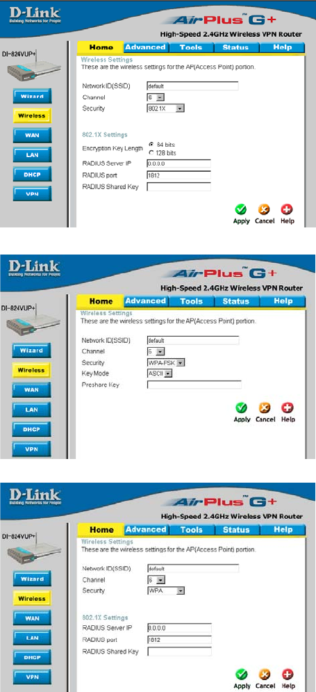
802.1x
RADIUS Server Enter the IP address and port number of the RADIUS server that
will be used as the 802.1x authenticator. Enter the secret key that
has also been entered into the RADIUS server’s configuration.
Encryption Key
The 802.1x is an authentication method which is designed to
compliment the existing WEP encryption. During the authentication
process, the server verifies the identity of the client attempting to
connect to the network. With the proper client account and encryption
key, access to the network is granted. Unfamiliar encryption key or
clients are denied from accessing the wireless network. This feature
will help safe guard a Local Area Network (LAN) from unwanted visitors.
To take the full advantage of the 802.1x in DI-824VUP, all of the
wireless devices on your network must be 802.1x compatible and
must have the 802.11x feature enabled to communicate with the
router. (Note: Windows 2000 users will find a few downloads to
enable 802.1x clients on the Microsoft website.)
Selection for Encryption Key
- 64 bits - This will generate a 10 digit Dynamic Key value for
encryption.
- 128 bits - This will generate a 26 digit Dynamic Key value for
encryption.
- 256bits - This will generate a 58 digit Dynamic Key value for
encryption.
- Lifetime - Select the period of time before a new Dynamic Key
is generated.
* Dynamic Keying is a
technique for changing
the WEP Key used
between the supplicant
(wireless client) and the
access point.
15
Using the Configuration Menu
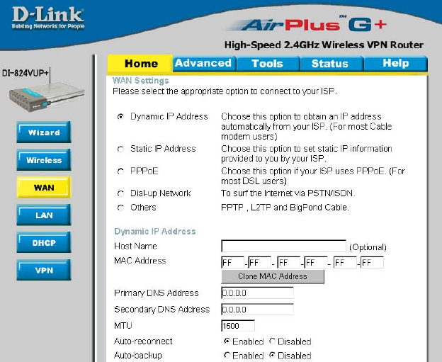
Home > WAN
Choose WAN Type
WAN stands for Wide Area Network. In this case WAN represents the mode in which
your ISP connects to the Internet. If you are uncertain, please ask your ISP which of the
following represents your connection mode to the Internet:
Static IP Address Your ISP assigns you a Static IP Address.
Dynamic
IP Address Obtain an IP address from your ISP automatically (mainly for
Cable users).
Others
For use in Europe only.
For use in Australia only.
PPTP
Big Pond Cable
PPP over Ethernet Some ISPs require the use of PPPoE to connect to their
services (mainly for DSL users).
Dial-up Network Dial-up users can select this option to connect to their ISP
through an analog dial-up modem if broadband connectivity
is unavailable.
16
Using the Configuration Menu
Home > WAN > Dynamic IP Address
Most Cable modem users will select this option to obtain an IP
Address automatically
from their ISP (Internet Service Provider).
Host Name This is optional, but may be required by some ISPs. The host
name is the device name of the Router.
MAC Address The default MAC Address is set to the WAN’s physical inter-
face MAC address on the Router.
Clone
MAC Address This feature will copy the MAC address of the Ethernet card,
and replace the WAN MAC address of the Router with this
Ethernet card MAC address. It is not recommended that you
change the default MAC address unless required by your ISP.
Renew IP Forever Enable this feature to allow the router to automatically recon-
nect to the ISP if the connection drops.
17
Using the Configuration Menu
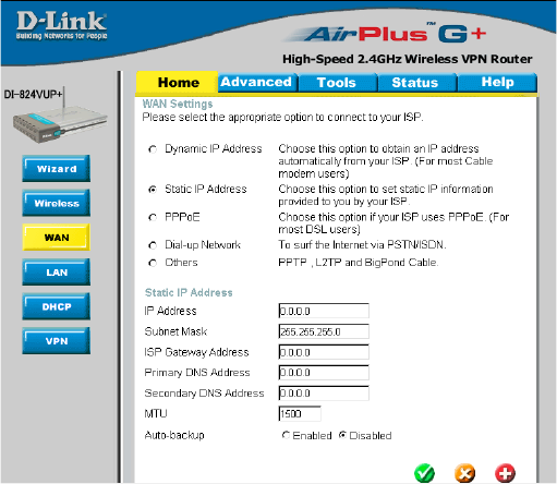
Home > WAN > Static IP Address
If you use a Static IP Address, you will input information here that your ISP has provided
to you.
Secondary DNS (Optional) Input the Secondary DNS address provided by your
ISP.
Primary DNS Input the primary DNS address provided by your ISP.
WAN Gateway Input the Gateway address provided by your ISP.
WAN Subnet Mask Input the Subnet Mask provided by your ISP.
WAN IP Address Input the IP Address provided by your ISP.
MTU Maximum Transmission Unit; default is 1500; you may need to
change the MTU to conform to your ISP.
Auto-backup Enabling this feature will connect your router to the Internet us-
ing a dial-up service if your broadband connection becomes un-
available. A subscription to a dial-up service is required for the
auto-backup to work.
18
Using the Configuration Menu
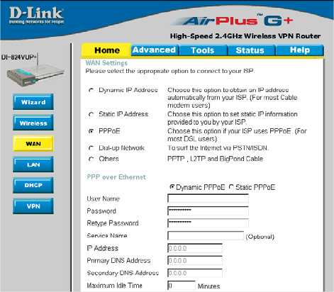
Home > WAN > PPPoE
Most DSL users will
select this option to
obtain an IP address
automatically from
their ISP through the
use of PPPoE.
MTU Maximum Transmission Unit; default is 1492; you may need to
change the MTU to conform to your ISP.
IP Address (Optional) Enter in the IP Address if you are assigned a static
PPPoE address.
Service Name (Optional) Check with your ISP for more information if they
require the use of service name.
Maximum
Idle Time Enter a maximum idle time during which Internet connection is
maintained during inactivity. To disable this feature, enable Auto-
reconnect.
Secondary DNS (Optional) Input the secondary DNS address.
Primary DNS You will get the DNS IP automatically from your ISP but you
may enter a specific DNS address that you want to use instead.
Password
Your PPPoE username provided by your ISP.
User Name
Your PPPoE password provided by your ISP.
Auto-reconnect If enabled, the Broadband Router will automatically connect to
your ISP after your system is restarted or if the connection is
dropped.
Auto-backup Enabling this feature will connect your router to the Internet us-
ing a dial-up service if your broadband connection becomes un-
available. A subscription to a dial-up service is required for the
auto-backup to work.
19
Using the Configuration Menu
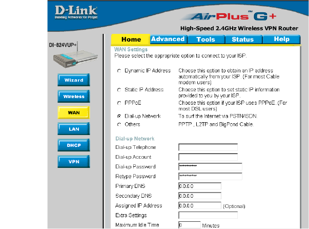
Home > WAN > Dial-up Network
Most Dial-up users will
select this option to con-
nect to their ISP through
an analog dial-up modem.
This feature can be used
as a back-up when your
broadband connectivity is
unavailable.
Extra Settings
Assigned
IP Address (Optional) Enter in the IP Address if you are assigned a static
PPPoE address.
Primary DNS/
Seconday DNS If the settings are configured as “0.0.0.0,” they will be auto-
matically assigned upon connection.
Baud Rate
Maximum Idle Time Enter a maximum idle time during which Internet connection
is maintained during inactivity. To disable this feature, en-
able Auto-reconnect.
Dial-up Password Password provided by your ISP
Dial-up Account
Telephone number to connect to your ISP
Dial-up Telephone
Username provided by your ISP
The communication speed between the DI-824VUP and your
modem.
This setting is used to optimize the communication quality
between the ISP and your analog dial-up modem. (Initializa-
tion string) - optional.
Auto-reconnect If enabled, the Broadband Router will automatically connect
to your ISP after your system is restarted or if the connection
is dropped.
20
Using the Configuration Menu
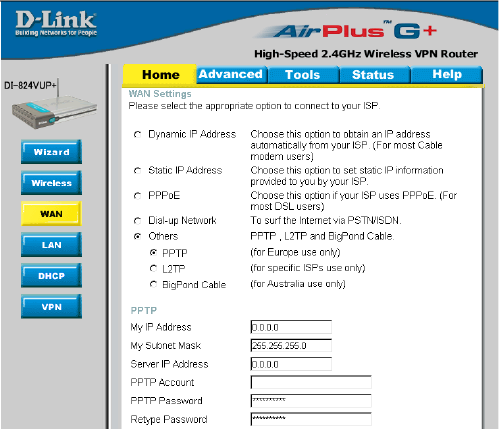
Home > WAN > Others > PPTP
PPTP Password Enter the PPTP password.
PPTP Account Enter the PPTP account name.
My Subnet Mask Enter the Subnet Mask.
Connection ID (Optional) Enter the connection ID if required by your ISP.
Maximum
Idle Time Enter a maximum idle time during which Internet connection is
maintained during inactivity. To disable this feature, enable Auto-
reconnect.
My IP Address Enter the IP Address.
Server IP Address Enter the Server IP Address.
Point-to-Point Tunneling Protocol (PPTP) is a WAN connection used in Europe.
Auto-reconnect If enabled, the Broadband Router will automatically connect to
your ISP after your system is restarted or if the connection is
dropped.
Auto-backup Enabling this feature will connect your router to the Internet
using a dial-up service if your broadband connection becomes
unavailable. A subscription to a dial-up service is required for
the auto-backup to work.
21
Using the Configuration Menu
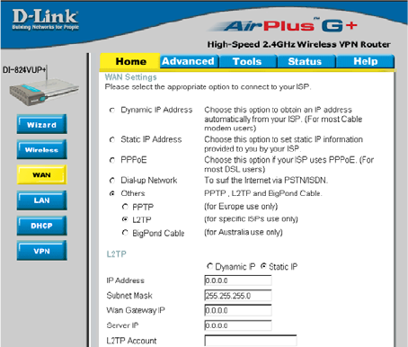
Home > WAN > Others > L2TP
L2TP password Your L2TP password provided by your ISP.
L2TP Account Your L2TP username provided by your ISP.
Subnet Mask Subnet mask provided by your ISP.
Retype Password Re-enter L2TP password.
Maximum Idle
Time Set it to zero or enable Auto-reconnect to disable this feature. If
Auto-reconnect is enabled, this product will automatically con-
nect to the ISP after the router is restarted or connection is
dropped.
IP Address IP address provided by your ISP.
Server IP IP Address of LNS provided by your ISP.
Auto-Reconnect If enabled, the Broadband Router will automatically connect to
your ISP after your system is restarted or if the connection is
dropped.
Layer 2 Tunneling Protocol(L2TP) is a WAN connenction used in Israel.
22
Using the Configuration Menu
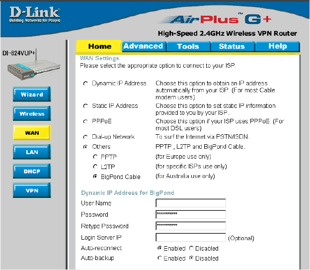
Home > WAN > Others > BigPond Cable
User Name Enter in the user name for the BigPond account.
Password Enter the password for the BigPond account.
Login Server IP (Optional) Enter the Login Server IP if required.
Dynamic IP Address for BigPond is a WAN connection used in Australia.
Auto-reconnect If enabled, the Broadband Router will automatically connect to
your ISP after your system is restarted or if the connection is
dropped.
Auto-backup Enabling this feature will connect your router to the Internet us-
ing a dial-up service if your broadband connection becomes un-
available. A subscription to a dial-up service is required for the
auto-backup to work.
23
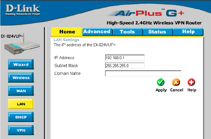
Home > LAN
Using the Configuration Menu
LAN is short for Local Area Network. This is considered your internal network. These are
the IP settings of the LAN interface for the DI-824VUP. These settings may be referred
to as Private settings. You may change the LAN IP address if needed. The LAN IP ad-
dress is private to your internal network and cannot be seen on the Internet.
Domain Name (Optional) The name of your local domain.
Subnet Mask The subnet mask of the LAN interface.
The default subnet mask is 255.255.255.0.
IP Address The IP address of the LAN interface.
The default IP address is: 192.168.0.1.
24
Using the Configuration Menu
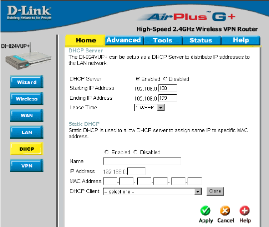
Home > DHCP
DHCP stands for Dynamic Host Control Protocol. The DI-824VUP has a built-in DHCP
server. The DHCP Server will automatically assign an IP address to the computers on
the LAN/private network. Be sure to set your computers to be DHCP clients by setting
their TCP/IP settings to “Obtain an IP Address Automatically.” When you turn your
computers on, they will automatically load the proper TCP/IP settings provided by the
DI-824VUP. The DHCP Server will automatically allocate an unused IP address from
the IP address pool to the requesting computer. You must specify the starting and
ending address of the IP address pool.
Lease Time The length of time for the DHCP lease.
DHCP Clients List Lists the DHCP clients connected to the DI-824VUP. Click Re-
fresh to update the list. The table will show the Host Name, IP
Address, and MAC Address of the DHCP client computer.
Enable or disable the DHCP service.
DHCP Server
Ending IP Address The ending IP address for the DHCP server’s IP assignment.
Starting IP Address The starting IP address for the DHCP server’s IP assignment.
Static DHCP Used to allow the DHCP server to assign the same IP adress to a
specific MAC address. Enter the name, IP address, and MAC
address into the fields. Select which DHCP client to clone.
25
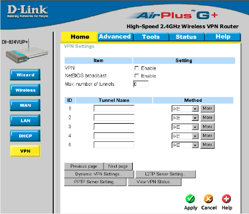
Home > VPN Settings
Using the Configuration Menu
VPN Settings are settings
that are used to create
virtual private tunnels to
remote VPN gateways. The
tunnel technology supports
data confidentiality, data
origin, authentication, and
data integrity of network
information by utilizing
encapsulation protocols,
encryption algorithms, and
hashing algorithms.
Max. number of
tunnels
Create a name for the tunnel.
NetBIOS broadcast
Click Enable to enable VPN tunnels. When you are not
using the VPN feature, it is best to keep VPN disabled.
VPN
Method IPSec VPN supports two kinds of key-obtained methods:
manual key and automatic key exchange. Manual key
approach indicates that the two endpoint VPN gateways
require setting up authentication and encryption key by
the Administrator manually. However, IKE approach will
perform automatic Internet key exchange. Admins of both
endpoint gateways will only need to set the same
pre-shared key.
For more in depth configuration to adjust manual key or IKE
method settings, click More.
More
Tunnel Name
Select the maximum number of allowable tunnels.
Enable this to allow NetBIOS braodcast over the VPN
tunnels.
26
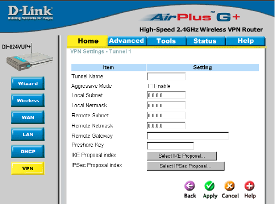
Remote Subnet The subnet of the remote VPN gateway’s local network. It
can be a host, a partial subnet, or a whole subnet.
Remote Netmask The subnet of the remote VPN gateway’s local network.
It can be a host, a partial subnet, or a whole subnet.
Remote Gateway The WAN IP address of remote VPN gateway.
Home > VPN Settings > Tunnel > Method >IKE
Using the Configuration Menu
Local Subnet The subnet of the VPN gateway’s local network. It can be a
host, a partial subnet or a whole subnet.
Local Netmask Local netmask combined with local subnet to form a subnet
domain.
Aggressive Mode Enabling this mode will accelerate establishing tunnel, but
the device will have less security.
Tunnel Name Current tunnel name.
IKE Proposal index Click the button to setup a set of frequent-used IKE proposals
and select from the set of IKE proposals for the tunnel.
IPSec Proposal
index
Click the button to setup a set of frequent-used IPSec proposals
and select from the set of IKE proposals for the tunnel.
Preshared Key The first key that supports IKE mechanism of both VPN
gateways for negotiating further security keys. The pre-
shared key must be the same for both endpoint gateways.
27
Using the Configuration Menu
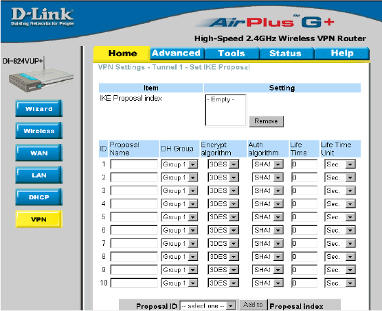
Home > VPN Settings > Tunnel > Method > IKE > Select IKE Proposal
IKE Proposal index
Proposal Name
DH Group
Encrypt algorithm
Auth algorithm
A list of selected proposal indexes from the IKE proposal pool
listed below.
There are three groups that can be selected: group 1
(MODP768), group 2 (MODP1024), and group 5 (MODP1536).
There are two algorithms that can be selected: 3DES and
DES.
There are two algorithms that can be selected: SHA1 and
MD5.
This is the name used to classify the IKE proposal.
28
Using the Configuration Menu
Home > VPN Settings > Tunnel > Method > IKE > Select IKE Proposal
Continued...
Life Time Enter in the life time value.
Life Time Unit There are two units that can be selected: second and KB.
Proposal ID The identifier of IKE proposal can be chosen for adding the
corresponding proposal to the dedicated tunnel.
Add to Click it to add the chosen proposal indicated by proposal ID
to IKE Proposal index list.

29
Using the Configuration Menu
Home > VPN Settings > Tunnel > Method > IKE > Select IPSEC Proposal
IPSec Proposal
index
A list of selected proposal indexes from the IPSec proposal
pool listed below.
Proposal Name
DH Group There are three groups that can be selected: group 1
(MODP768), group 2 (MODP1024), and group 5 (MODP1536).
Encap protocol There are two protocols that can be selected: ESP and AH.
Encrypt algorithm There are two algorithms that can be selected: 3DES and
DES.
This is the name used to classify the IPSec Proposal
Auth algorithm There are two algorithms that can be selected: SHA1 and
MD5.

30
Using the Configuration Menu
Home > VPN Settings > Tunnel > Method > IKE > Select IPSEC Proposal
Continued...
Life Time Enter in a life time value.
Life Time Unit There are two units that can be selected: second and KB.
Proposal ID The identifier of IPSec proposal can be chosen for adding the
corresponding proposal to the dedicated tunnel.
Add to Click it to add the chosen proposal indicated by proposal ID
to IPSec Proposal index list.
31
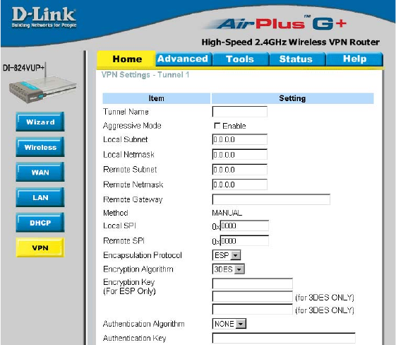
Using the Configuration Menu
Home > VPN Settings > Tunnel > Manual
Remote Subnet The subnet of the remote VPN gateway’s local network. It
can be a host, a partial subnet, or a whole subnet.
Remote Netmask The subnet of the remote VPN gateway’s local network.
It can be a host, a partial subnet, or a whole subnet.
Remote Gateway The WAN IP address of remote VPN gateway.
Local Subnet The subnet of the VPN gateway’s local network. It can be a
host, a partial subnet, or a whole subnet.
Local Netmask Local netmask combined with local subnet to form a subnet
domain.
Aggressive Mode Enabling this mode will accelerate establishing tunnel, but
the device will have less security.
Tunnel Name Current tunnel name.
Remote SPI The value of the remote SPI should be set in hex format.
Local SPI The value of the local SPI should be set in hex format.
Method The set of rules applied when connecting to the VPN gateway.

32
Using the Configuration Menu
Home > VPN Settings > Tunnel > Manual Continued...
Encapsulation
Protocol
There are two protocols that can be selected: ESP and AH.
Encryption
Algorithm
There are two algorithms that can be selected: 3DES and DES.
Authentication
Algorithm
There are two algorithms that can be selected: SHA1 and MD5.
Encryption Key For DES, the encryption key is 8 bytes (16 Char.). For 3DES,
the encryption key is 24 bytes (48 Char.).
Authentication Key For MD5, the authentication algorithm is16 bytes (32 Char.).
For SHA1, the authentication algorithm is 20 bytes.(40 Char.).
Life Time Enter in the life time value.
Life Time Unit There are two units that can be selected: Second and KB.
33
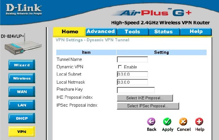
Home > VPN Settings > Dynamic VPN Tunnel
Using the Configuration Menu
Local Subnet The subnet of the VPN gateway’s local network. It can be a
host, a partial subnet, or a whole subnet.
Local Netmask The netmask of the VPN gateway’s local network.
Aggressive Mode Enabling this mode will accelerate establishing the tunnel,
but the device will have less security.
Tunnel Name Current tunnel name.
This feature works with a VPN software client so the DI-
824VUP does not need to know the IP address of the re-
mote clients.
Dynamic VPN
There are three parts that are necessary to setup the
configuration of IKE for the dedicated tunnel: basic setup, IKE
proposal setup, and IPSec proposal setup. Basic setup
includes the setting of following items: local subnet, local
netmask, remote subnet, remote netmask, remote gateway,
and pre-shared key. The tunnel name is derived from the previous
page of VPN setting. IKE proposal setup includes the setting
of a set of frequent-used IKE proposals and selecting from the
set of IKE proposals.
VPN Settings - IKE

34
Using the Configuration Menu
Home > VPN Settings > Dynamic VPN Tunnel Continued...
Preshared Key The first key that supports IKE mechanism of both VPN
gateways for negotiating further security keys. The pre-
shared key must be the same for both endpoint gateways.
IKE Proposal index Click the button to setup a set of frequent-used IKE
proposals and select from the set of IKE proposals for the
dedicated tunnel.
IPSec Proposal
index
Click the button to setup a set of frequent-used IPSec
proposals and select from the set of IKE proposals for the
dedicated tunnel.

35
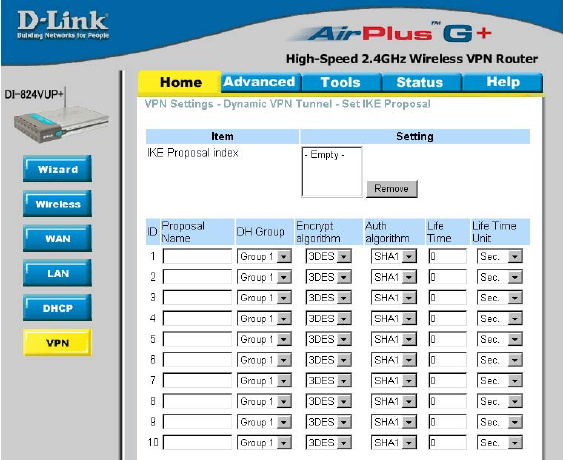
Using the Configuration Menu
Home > VPN Settings > Dynamic VPN Tunnel > Set IKE Proposal
IKE Proposal index
Proposal Name
DH Group
Encrypt algorithm
Auth algorithm
A list of selected proposal indexes from the IKE proposal
pool listed below.
There are three groups that can be selected: group 1
(MODP768), group 2 (MODP1024), and group 5 (MODP1536).
There are two algorithms that can be selected: 3DES and
DES.
It indicates which IKE proposal to be focused.
There are two algorithms that can be selected: SHA1 and
MD5.
36
Life Time Enter in the life time value.
Life Time Unit There are two units that can be selected: second and KB.
Proposal ID The identifier of IKE proposal can be chosen for adding the
corresponding proposal to the dedicated tunnel.
Add to Click it to add the chosen proposal indicated by proposal ID
to IKE Proposal index list.
Using the Configuration Menu
Home > VPN Settings > Dynamic VPN Tunnel > Set IKE Proposal
Continued...
37
Using the Configuration Menu
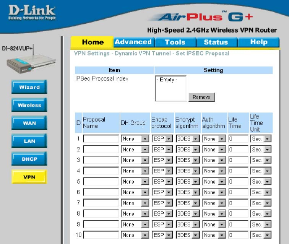
Home > VPN Settings > Dynamic VPN Tunnel > Set IPSEC Proposal
IPSec Proposal
index
A list of selected proposal indexes from the IPSec proposal
pool listed below.
Proposal Name
DH Group There are three groups that can be selected: group 1
(MODP768), group 2 (MODP1024), and group 5 (MODP1536).
Encap protocol There are two protocols that can be selected: ESP and AH.
Encrypt algorithm There are two algorithms that can be selected: 3DES and
DES.
This is the name used to classify the IPSec proposal.
Auth algorithm There are two algorithms that can be selected: SHA1 and
MD5.

38
Using the Configuration Menu
Home > VPN Settings > Dynamic VPN Tunnel > Set IPSEC Proposal
Continued...
Life Time Enter in a life time value.
Life Time Unit There are two units that can be selected: second and KB.
Proposal ID The identifier of IPSec proposal can be chosen for adding the
corresponding proposal to the dedicated tunnel.
Add to Click it to add the chosen proposal indicated by proposal ID
to IPSec Proposal index list.
39
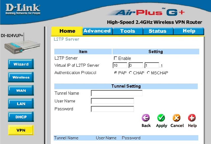
Home > VPN Settings > L2TP Server Setting
Using the Configuration Menu
Enable L2TP
Server
Click to enable the L2TP Server function.
Virtual IP of
L2TP Server Enter your Virtual IP address to access the L2PT server.
Authentication
Protocol
Select one of the following authentication protocols: PAP,
CHAP, or MSCHAP.
Tunnel Name Current tunnel name.
User Name
Password Enter in the password for the L2TP account.
Enter in the username for the L2TP account.
40
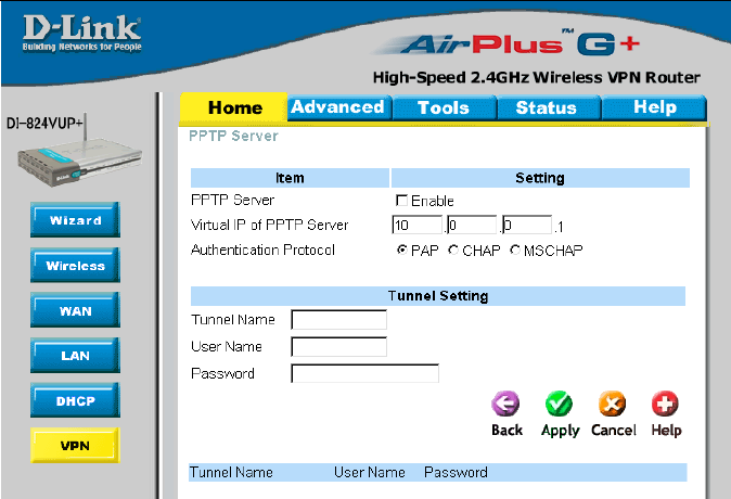
Home > VPN Settings > PPTP Server Setting
Using the Configuration Menu
Enable PPTP
Server
Click to enable the PPTP Server function.
Virtual IP of
PPTP Server
Enter your Virtual IP address to access thePPPT server.
Authentication
Protocol
Select one of the following authentication protocols: PAP,
CHAP, or MSCHAP.
Tunnel Name Current tunnel name.
User Name
Password Enter in the password for the PPTP account.
Enter in the username for the PPTP account.
41
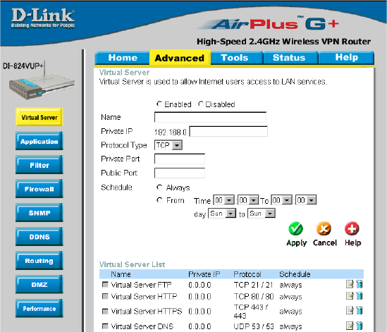
Advanced > Virtual Server
Using the Configuration Menu
The DI-824VUP can be configured as a virtual server so that remote users accessing
Web or FTP services via the public IP address can be automatically redirected to local
servers in the LAN (Local Area Network).
The DI-824VUP firewall feature filters out unrecognized packets to protect your LAN
network so all computers networked with the DI-824VUP are invisible to the outside
world. If you wish, you can make some of the LAN computers accessible from the
Internet by enabling Virtual Server. Depending on the requested service, the DI-824VUP
redirects the external service request to the appropriate server within the LAN network.
Protocol Type The protocol used for the virtual service.
Public Port The port number on the WAN side that will be used to access
the virtual service.
Private IP The server computer in the LAN network that will be providing
the virtual services.
Name The name referencing the virtual service.
Private Port The port number of the service used by the Private IP computer.
Schedule Select Always, or choose From and enter the time period dur-
ing which the virtual service will be available.
42
Using the Configuration Menu
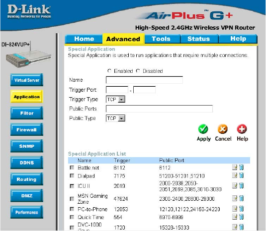
Advanced > Application
Some applications require multiple connections, such as Internet gaming, video
conferencing, Internet telephony, and others. These applications have difficulties working
through NAT (Network Address Translation). Special Applications makes some of these
applications work with the DI-824VUP. If you need to run applications that require multiple
connections, specify the port normally associated with an application in the Trigger
field, then enter the public ports associated with the trigger port into the Incoming Ports
field.
At the bottom of the screen, there are already defined special applications. To use them,
select one from the drop down list and select an ID number you want to use. Then click
the “Copy to” button and the router will fill in the appropriate information to the list. You
will then need to enable the service. If the mechanism of Special Applications fails to
make an application work, try using DMZ host instead.
Note! Only one PC can use each Special Application tunnel.
Trigger Port This is the port used to trigger the application. It can be
either a single port or a range of ports.
Public Ports This is the port number on the WAN side that will be used to
access the application. You may define a single port or a range
of ports. You can use a comma to add multiple ports or port
ranges.
Enabled Select to activate the policy.
43
Using the Configuration Menu
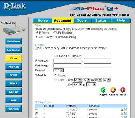
Advanced > Filter > IP Filter
IP Filter
Use IP Filters to deny LAN IP addresses access to the internet.
Protocol
IP Address
Enter in the IP address range of the computers that you want the policy to apply to. If it
is only a single computer that you want the policy applied to, then enter the IP address of
that computer in the Start Source IP and leave the End Source IP blank.
Use IP (Internet Protocol)
filters to allow or deny
computers access to the
Internet based on their IP
address.
Port Range
Enter in the port range of the TCP/UDP ports that you want the policy to apply to. If it is
only a single port that you want the policy applied to, then enter the port number in the
Start Port field and leave the End Port field blank. If you want to use all the ports, you can
leave the port range empty.
Enabled or Disabled
Click Enabled to apply the filter policy or click Disabled to enter an inactive filter policy.
(You can reactivate the policy later.)
Select the protocol type to allow or deny certain types of IP addresses.
Schedule
Select Always, or choose From and enter the time period during which the IP filter policy
will be in effect.
44
Using the Configuration Menu
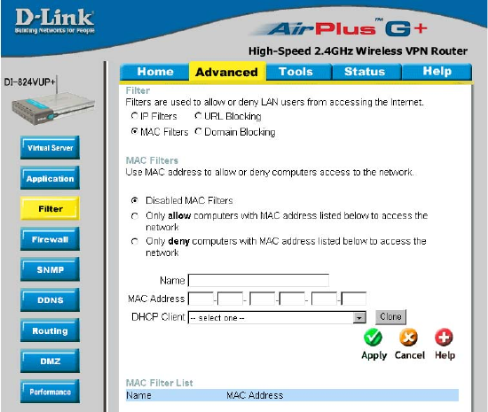
Advanced > Filter > MAC Filters
MAC (Media Access Control) Filters are used to allow or deny LAN (Local Area Network)
computers from accessing the Internet and network by their MAC address.
At the bottom of the screen, there is a list of MAC addresses from the DHCP client
computers connected to the DI-824VUP. To use them, select one from the drop down
list. Then click the “Apply” button and the DI-824VUP will fill in the appropriate information
to the list.
Disabled MAC Filter
Select this option if you do not want to use MAC filters.
Only allow computers with MAC address listed below to access the network
Select this option to only allow computers that are in the list to access the network
and Internet. All other computers will be denied access to the network and
Internet.
Only deny computers with MAC address listed below to access the network
Select this option to only deny computers that are in the list to access the network
and Internet. All other computers will be allowed access to the network and Internet.
Enter the MAC Address of the client that will be filtered.
MAC Address
45
Using the Configuration Menu
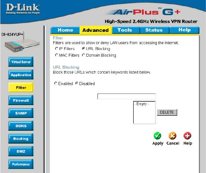
Advanced > Filter > URL Blocking
Use URL Blocking to deny LAN computers from accessing specific web sites by its
URL. A URL is a specially formatted text string that defines a location on the Internet.
If any part of the URL contains the blocked word, the site will not be accessible and
the web page will not display.
Disabled URL Blocking
Select this option if you do not want to use URL Blocking.
46
Using the Configuration Menu
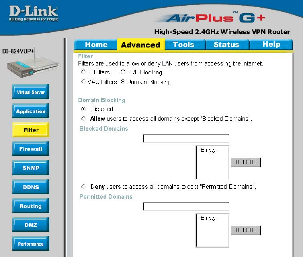
Advanced > Filter > Domain Blocking
Use Domain Blocking to allow or deny computers access to specific Internet domains
whether it is through www, ftp, snmp, etc.
Disabled Domain Blocking
Select this option if you do not want to use Domain Blocking.
Allow users to access all domains except “Blocked Domains”
Select this option to allow users to access the specified Internet domains listed below.
Users will be denied access to all other Internet domains.
Deny users to access all domains except “Permitted Domains”
Select this option to deny users to access the specified Internet domains listed below.
Users will be allowed access to all other Internet domains.

47
Using the Configuration Menu
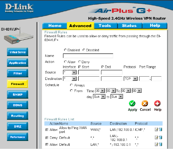
Advanced > Firewall
Firewall Rules is an advance feature used to allow or deny traffic from passing through
the device. It works in the same way as IP Filters with additional settings. You can
create more detailed rules for the device.
Enabled or Disabled
Click Enabled to apply the filter policy or click Disabled to enter an inactive filter policy
(You can reactivate the policy later).
Name
Enter the name of the Firewall Rule.
Action
Select Allow or Deny to allow or deny traffic to pass through the DI-824VUP.
Source
Choose between a LAN or WAN source. An asterisk signifies the selection of both sources.
IP Start
The starting IP address for the filter policy. Leaving the field blank selects all IPs.
IP End
The ending IP address for the filter policy. Leaving the field blank sleects all IPs.
Destination
Choose between a LAN or WAN destination. An asterisk signifies the selection of both
destinations.
48
Using the Configuration Menu
Advanced > Firewall Continued
Schedule
Select Always, or choose From and enter the time period during which the virtual service
will be available.
IP Address
Enter in the IP address range of the computers that you want the policy to apply to. If it
is only a single computer that you want the policy applied to, then enter the IP address of
that computer in the Start Source IP and leave the End Source IP blank.
Port Range
Enter in the port range of the TCP/UDP ports that you want the policy to apply to. If it is
only a single port that you want the policy applied to, then enter the port number in the
Start Port field and leave the End Port field blank. If you want to use all the ports, you can
leave the port range empty.
Protocol
Select one of the following protocols: TCP, UDP, or ICMP.
49
Using the Configuration Menu
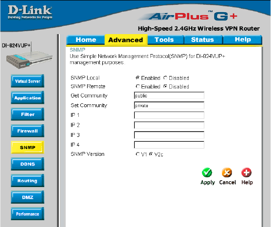
Advanced > SNMP
SNMP (Simple Network Management Protocol) is a widely used network monitoring and
control protocol that reports activity on each network device to the administrator of the
network. SNMP can be used to monitor traffic and statistics of the DI-824VUP. The DI-
824VUP supports SNMP v1 or v2c.
Enable SNMP
Get Community
(Simple Network Management Protocol.)
Enter the password public in this field to allow “Read only”
access to network administration using SNMP. You can view
the network, but no configuration is possible wth this setting.
Set Community Enter the password private in this field to gain “Read and Write”
access to the network using SNMP software. The administra-
tor can configure the network with this setting.
Local
Remote WAN (Wide Area Network).
LAN (Local Area Network).
SNMP v1 Simple Network Management Protocol (SNMP) is an application
layer protocol that facilitates the exchange of management infor-
mation between nework devices.
SNMP v2 Enhanced version of SNMP v1 with additional protocol opera-
tions such as UDP, IP, CLNS, DDP, and IPX.
50
Using the Configuration Menu
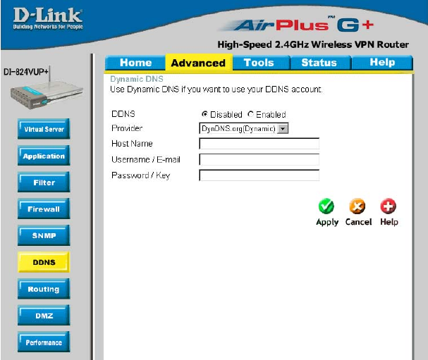
Advanced > DDNS
DDNS (Dynamic Domain Name System) keeps dynamic IP addresses (e.g., IP
addresses assigned by a DHCP capable router or server) linked to a domain name.
Users who have a Dynamic DNS account may use this feature on the DI-824VUP.
DDNS When an IP address is automatically assigned by a DHCP server,
DDNS automatically updates the DNS server. Select Disabled
or Enabled.
Provider Select from the pull-down menu.
Host Name Enter the Host name.
Username/Email Enter the username or email address.
Password/Key Enter the password or key.
51
Using the Configuration Menu
Advanced > Routing
Static routes can be added if
you require specific routes
within your internal network.
These routes will not apply to
the WAN (Internet) network.
Enable Select this option for the specified static route to take effect.
Hop Count - In a transmission path, each link is terminated at a network device
such as a router or gateway. The number of hops equals the number of routers or
gateways that data must pass through before reaching the destination.
Dynamic Routing Settings allow the VPN Router to route IP
packets to another network automatically. The RIP protocol is
applied, and broadcasts the routing information to other routers
on the network regularly.
Dynamic Routing
RIP v1 Protocol in which the IP address is routed through the internet.
RIP v2 Enhanced version of RIP v1with added features such as Au-
thentication, Routing Domain, Next Hop Fowarding, and Subnet-
mask Exchange.
Destination Enter in the IP of the specified network that you want to
access using the static route.
Subnet Mask Enter in the subnet mask to be used for the specified net
work.
Gateway Enter in the gateway IP address to the specified network.
Hop Enter in the amount of hops it will take to the specified
network.
By default, it is set to disable. Check to enable (RIPv1 / RIPv2)
protocol.
52
Using the Configuration Menu
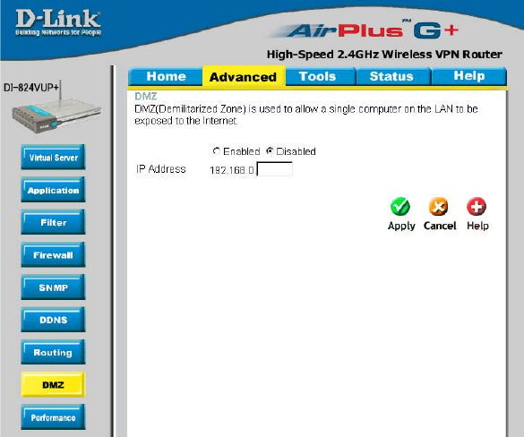
Advanced > DMZ
If you have a computer that cannot run Internet applications properly from behind the DI-
824VUP, then you can allow that computer to have unrestricted Internet access. Enter
the IP address of that computer as a DMZ (Demilitarized Zone) host with unrestricted
Internet access. Adding a client to the DMZ may expose that computer to a variety of
security risks; so only use this option as a last resort.

53
Using the Configuration Menu
Advanced > Performance
Beacon Interval Beacons are packets sent by an Access Point to synchronize a
wireless network. Specify a value. 100 is the default setting and is
recommended.
TX Rates Select the data rate. Default is 1-2-5.5-11-22-54Mbps.
DTIM interval (Delivery Traffic Indication Message) 3 is the default setting. A DTIM
is a countdown informing clients of the next window for listening to
broadcast and multicast messages.
Wireless Mode
G Mode
The DI-824VUP will use either B or G mode depending on which
mode has a stronger frequency.
Mixed Mode
The DI-824VUP will only use G mode.
Select either mix mode or G mode.
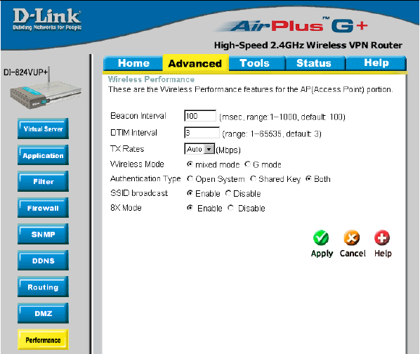
54
Shared Key In this mode, in order to access the DI-824VUP on the network,
the device must be listed in the MAC Address Control List.
Both In this mode, all devices on the network can access the
DI-824VUP.
Authentication Select Open system, Shared Key or Both.
SSID Broadcast Enable is the default setting. Choose Enable to broadcast the SSID
across the network. All devices on a network must share the same
SSID (Service Set Identifier) to establish communication. Choose
Disable if you do not wish to broadcast the SSID over the network.
The DI-824VUP will be visible to all devices on the network. This is
the default setting.
Open System
Using the Configuration Menu
Advanced > Performance (Continued)
8x Enable 8X Mode on the wireless client and the DI-824VUP to
increase data transmission speed. 8X Mode will only work with
wireless devices that also support 8X Mode.
55
Using the Configuration Menu
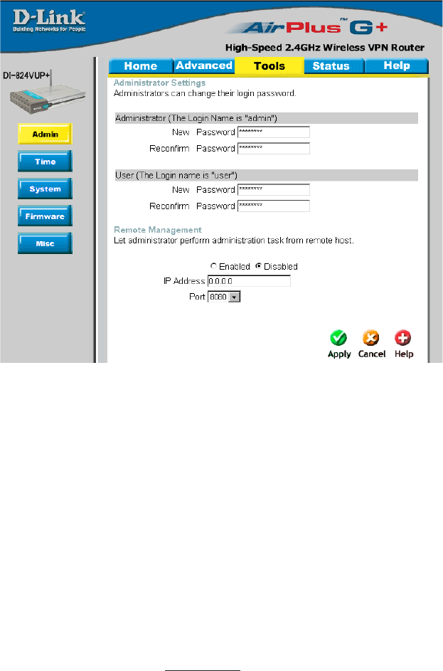
Tools > Admin
Password
Remote
Management
To change the administrator or user password, enter in the old pass-
word and enter the new password twice to confirm.
You can change the administrator and user passwords here. It is recommended that you
change the administrator password from the default setting.The default password is blank
(nothing).
Remote Management allows the device to be configured through
the WAN (Wide Area Network) port from the Internet using a web
browser. A username and password is still required to access the
browser-based management interface.
IP Address Internet IP Address of the computer that has access to the DI-
824VUP. If the IP Address is set to 0.0.0.0, this allows all Internet
IP addresses to access the DI-824VUP.
Port The port number used to access the DI-824VUP.
Example:http://x.x.x.x:8080, where x.x.x.x. is the WAN IP address
of the DI-824VUP and 8080 is the port used for the Web Manage-
ment interface.
56
Using the Configuration Menu
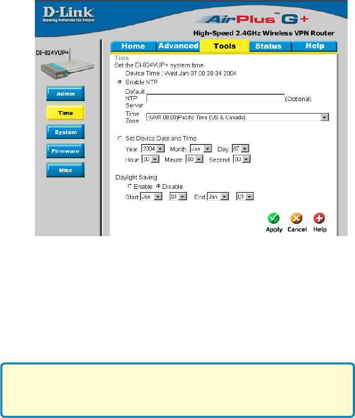
Tools > Time
Enable NTP (Network Time Protocol). Select to synchronize the time on the
DI-824VUP to an NTP server.
Set Device Date
and Time You can manually set the time on your network here.
You will need to set the time zone corresponding to your location. The time can be
set manually or the device can connect to a NTP (Network Time Protocol) server to
retrieve the time.
NTP is short for Network Time Protocol, an Internet standard protocol
that assures accurate synchronization to the millisecond of computer
clock times in a network of computers.
57
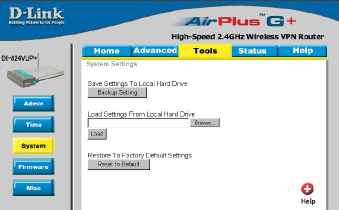
Using the Configuration Menu
Tools > System
Click Save to save the current settings to the local Hard Drive.
Click Browse to find the settings file, then click Load.
Save Settings to
Local Hard Drive
Load Settings from
Local Hard Drive
Restore to Factory
Default Settings Click Restore to restore the factory default settings.
The current system settings can be saved as a file onto the local hard drive. The saved
file or any other saved setting file created by the DI-824VUP can be uploaded into the
unit. To reload a system settings file, click on “Browse” to search the local hard drive
for the file to be used. The device can also be reset back to factory default settings by
clicking on “Reset to Default” button. Use the restore feature only if necessary. This will
erase previously saved settings for the unit. Make sure to save your system settings
before doing a factory restore.
58
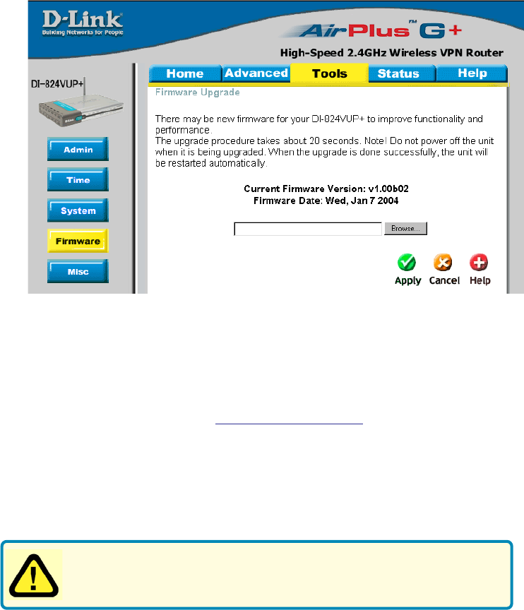
Using the Configuration Menu
Tools > Firmware
Browse After you have downloaded the new firmware, click Browse in
this window to locate the firmware update on your hard drive.
Click Apply to complete the firmware upgrade.
Note! Do not power off the unit when it is being upgraded. When the
upgrade is complete, the unit will be restarted automatically.
You can upgrade the firmware of the device using this tool. Make sure that the firmware
you want to use is saved on the local hard drive of the computer. Click on “Browse” to
search the local hard drive for the firmware to be used for the update. Upgrading the
firmware will not change any of your system settings but it is recommended that you
save your system settings before doing a firmware upgrade. Please check the D-Link
support site for firmware updates at http://support.dlink.com.

59
Using the Configuration Menu
Tools > Misc
Block WAN Ping Click Enable to block the WAN ping. Computers on the Internet
will not get a reply back from the DI-824VUP when it is being
“ping”ed. This may help to increase security.
Restart Device Click Reboot to restart the unit.
Ping Test In the open box, enter in a URL (i.e., www.dlink.com) or an IP
address and click on Ping to test your internet connection.
SPI Mode When this feature is enabled, the router will record the packet
information passed through the router such as IP address, port
address, ACK, SEQ number, and so on. The router will also check
every incoming packet to detect if it is valid.
DoS When DoS is enabled, the router will prevent Denial of Service
attacks on all computers connected to the DI-824VUP.
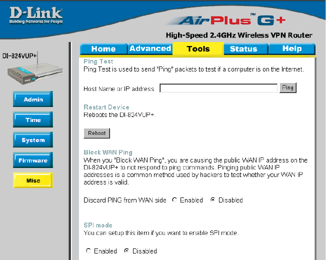
60
Using the Configuration Menu
Tools > Misc (Continued)
Non-standard
FTP port If an FTP server you want to access is not using the standard port
21, then enter in the port number that the FTP server is using in-
stead.
UPnP UPnP is short for Universal Plug and Play which is a networking
architecture that provides compatibility among networking equipment,
software, and peripherals. The DI-824VUP is a UPnP enabled router
and will only work with other UPnP devices/softwares. If you do not
want to use the UPnP Functionality, it can be disabled by selecting
“Disabled”.
VPN Pass-
Through The device supports VPN (Virtual Private Network) pass-through for
both PPTP (Point-to-Point Tunneling Protocol) and IPSec (IP Secu-
rity). Once VPN pass-through is enabled, there is no need to open
up virtual services. Multiple VPN connections can be made through
the device. This is useful when you have many VPN clients on the
LAN.
61
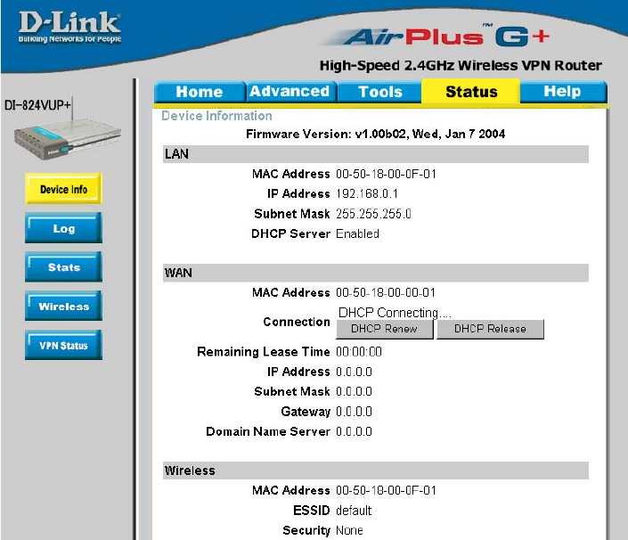
Using the Configuration Menu
Status > Device Info
This screen displays information about the DI-824VUP such as WAN, LAN, and Wire-
less status.
DHCP Renew Use this button to reconnect to your ISP, if your WAN connection is
set up for DHCP.
DHCP Release Use this button to disconnect from your ISP, if your WAN connection
is set up for DHCP.
62
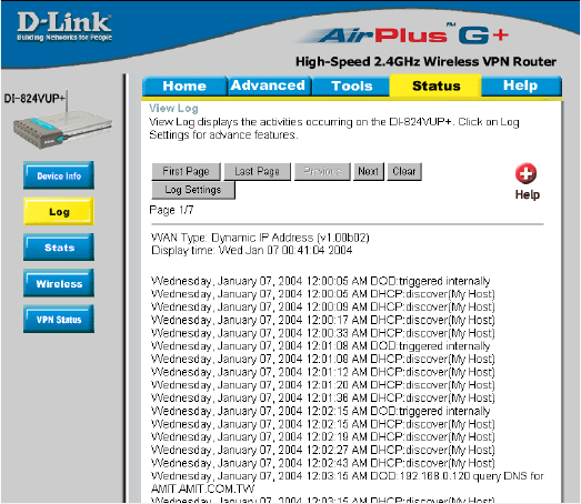
Using the Configuration Menu
Status > Log
This screen displays activities occurring on the DI-824VUP.
Log Settings Click for advanced features (see next page).
First Page Click First Page to go to the first page of the log.
Last Page Click Last Page to go to the last page of the log.
Previous Click Previous to go to the previous page of the log.
Next Click Next to go to the next page of the log.
Clear Click Clear to clear the current page of the log.
63
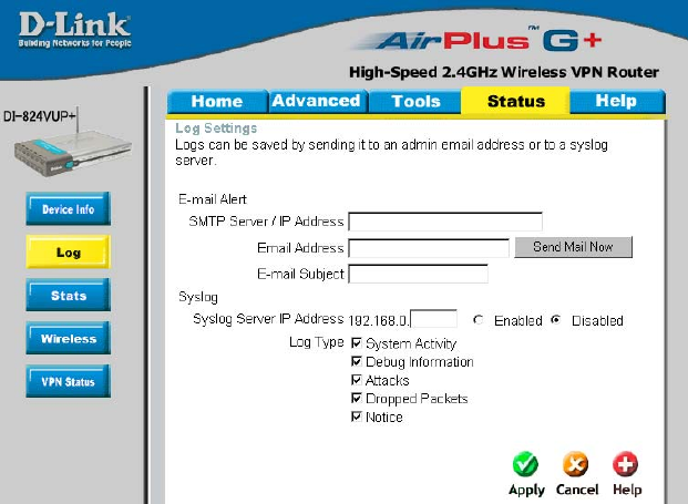
Using the Configuration Menu
Status > Log > Log Settings
Email Address Enter in the email address of the recipient who will receive the
email log.
Enter in the IP address of a syslog server within the network.
Click Enable to activate the policy. The DI-824VUP will send
all of it’s logs to the specified syslog server.
IP Address of the
Syslog Server
E-Mail Alert The DI-824VUP can be set up to send the log files to a spe-
cific email address.
SMTP Server IP Enter in the IP address of the mail server.
Send Mail Now Click to send mail immediately.
Log Type Select the types of activity to log. By default, all values are
selected.
64
Using the Configuration Menu
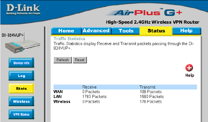
Status > Stats
In the Stats section, traffic statistics are displayed.
Refresh This will update the page.
Reset This will reset the packet counter to zero.
WAN Displays Received / Transmitted packets from the WAN port.
LAN Displays Received / Transmitted packets from the LAN port.
65
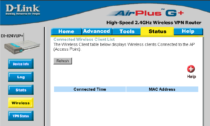
This screen displays the connection time and the MAC Address of the connected
wireless clients. Click on Refresh for the most recent information.
Using the Configuration Menu
Status > Wireless
66
Using the Configuration Menu
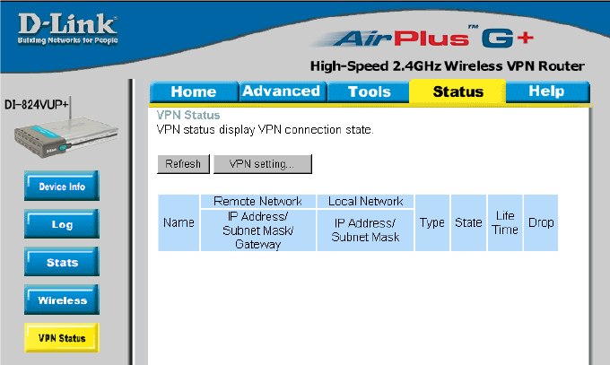
Status > Wireless
This screen displays the VPN connection state.
Click on Refresh for the most recent information.
67
Using the Configuration Menu
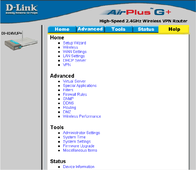
Help
This screen displays the complete Help menu. For help at anytime, click the Help tab in
the Configuration menu.
68
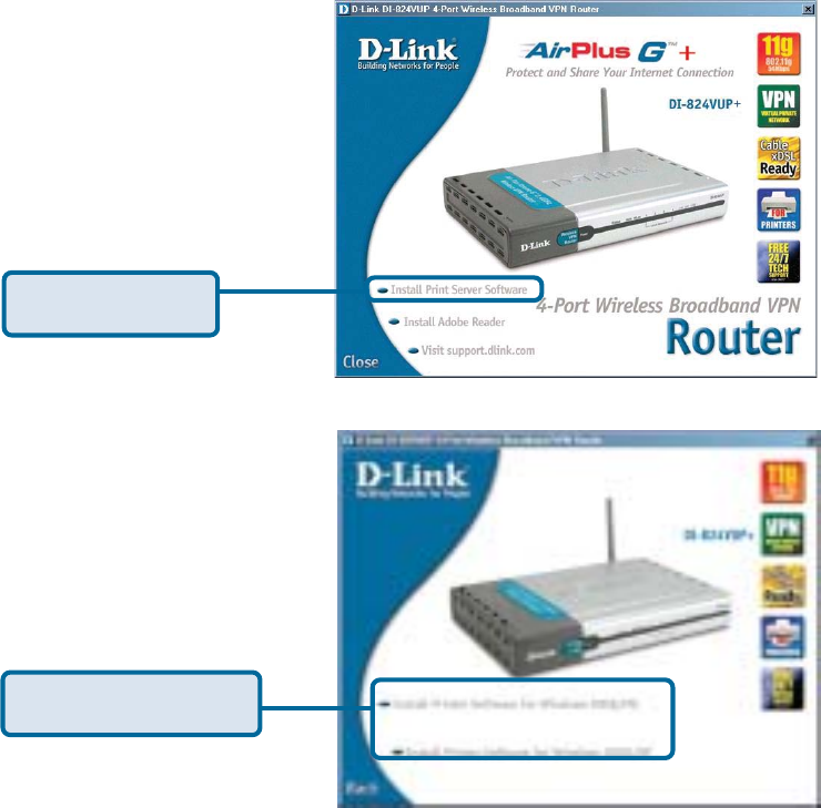
Insert the installation CD-ROM into the CD-ROM drive. The following window will be
shown automatically. If it is not, please run “autorun.exe” on the CD-ROM.
Installing the Print Server Software
Click Install Print
Server Software
Select your Windows
operating system
69
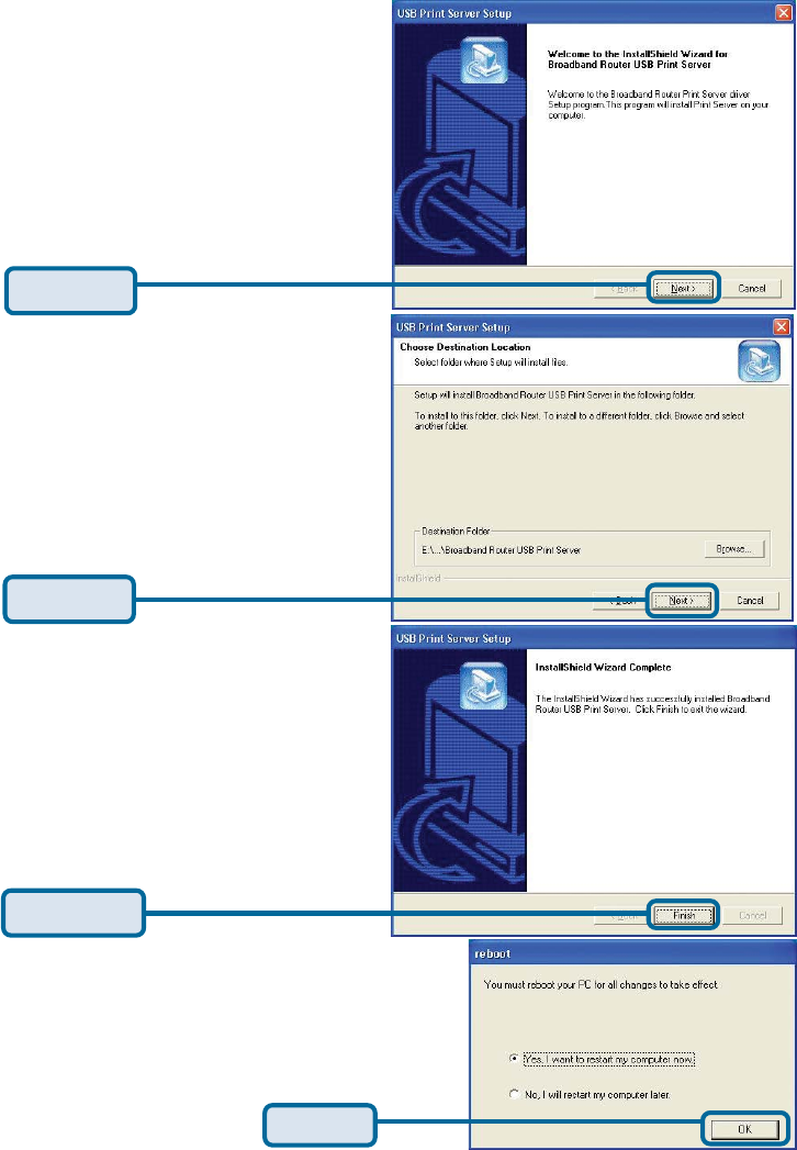
Wait until the following Welcome
dialog appears.
Select the destination folder.
After rebooting your
computer, the software
installation procedure is
finished.
Installing the Print Server Software (continued)
Then, the setup program will begin
to install the programs into the
destination folder.
When the following window is
displayed.
Click Next
Click Next
Click Finish
Click OK
70
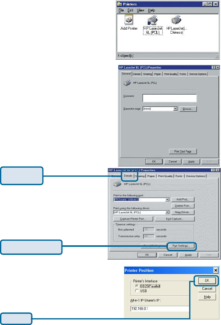
Configuring on Windows 98se/Me Platforms
After you finish the software installation pro-
cedure, your computer will be capable of
network printing provided by the DI-
824VUP. For convenience, we call the
printer connected to the printer port of the
DI-824VUP a printer server. On a Win-
dows 95/98 platform, open the Printers
window in the My Computer menu.
Now, you can configure the print server of
the DI-824VUP:
Find out the corresponding icon of your
printer server, for example, the HP
LaserJet 6L. Right click on that icon, and
then select Properties.
The following screen appears:
Choose the “PRTmate: (All-in-1)”
from the list attached at the Print To
item. Be sure that the Printer Driver
item is configured to the correct driver
of your printer server.
Choose your printer interface.
Type in the IP address of the DI-824VUP.
Click on the
Details tab
Click Port Settings
Click OK
71
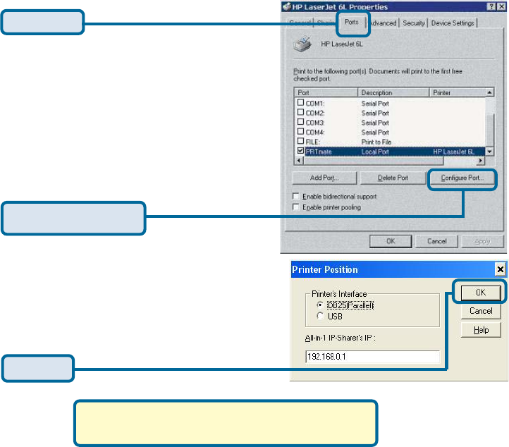
Configuring on Windows 2000/XP Platforms
The configuration procedure for a
Windows 2000/XP platform is similar to
that of Windows 95/98 except the
screen of printer Properties.
(Note: Screen shots are taken in Windows 2000,
similar screens will appear in Windows XP.)
Click Port
Click Configure Port
Choose your printer interface.
Type in the IP address of the DI-824VUP.
Click OK
72
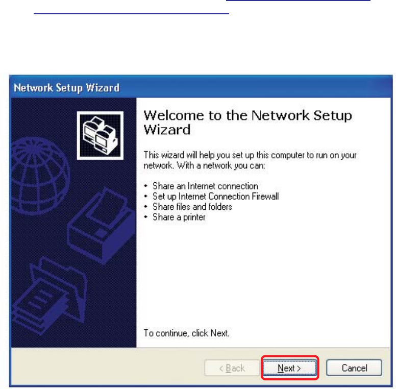
Using the Network Setup Wizard in Windows XP
In this section you will learn how to establish a network at home or work,
using Microsoft Windows XP.
Note: Please refer to websites such as http://www.homenethelp.com
and http://www.microsoft.com/windows2000 for information about networking
computers using Windows 2000, ME or 98.
Go to Start > Control Panel > Network Connections
Select Set up a home or small office network
Networking Basics
When this screen appears, Click Next.
73
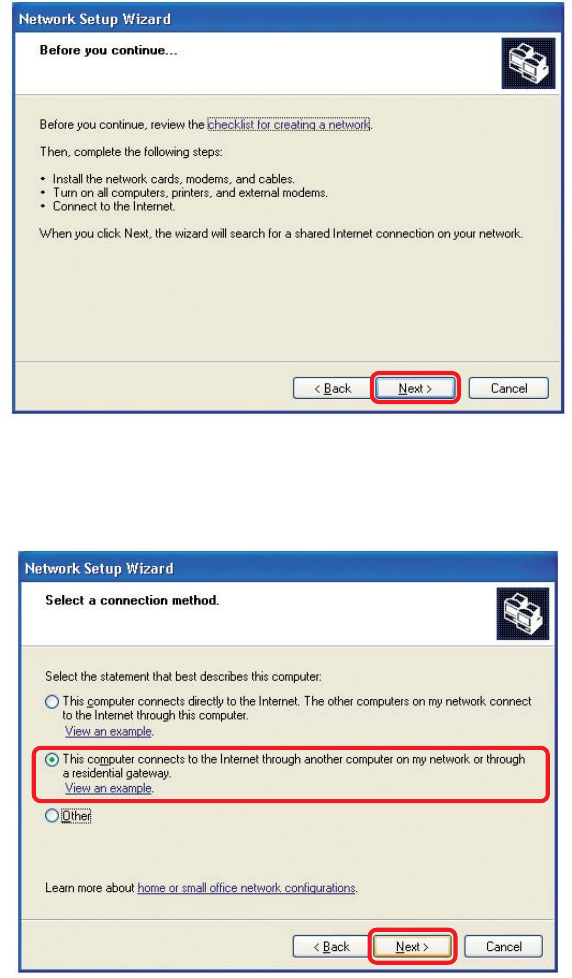
Please follow all the instructions in this window:
Networking Basics
Click Next.
In the following window, select the best description of your computer. If your
computer connects to the internet through a gateway/router, select the
second option as shown.
Click Next.
74
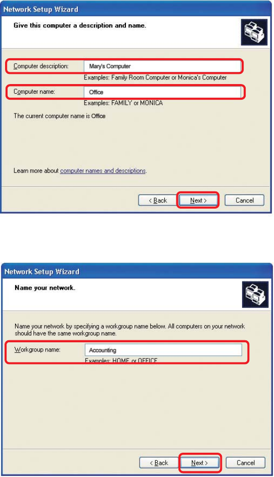
Enter a Computer description and a Computer name (optional).
Networking Basics
Click Next.
Enter a Workgroup name. All computers on your network should have the
same Workgroup name.
Click Next.
75
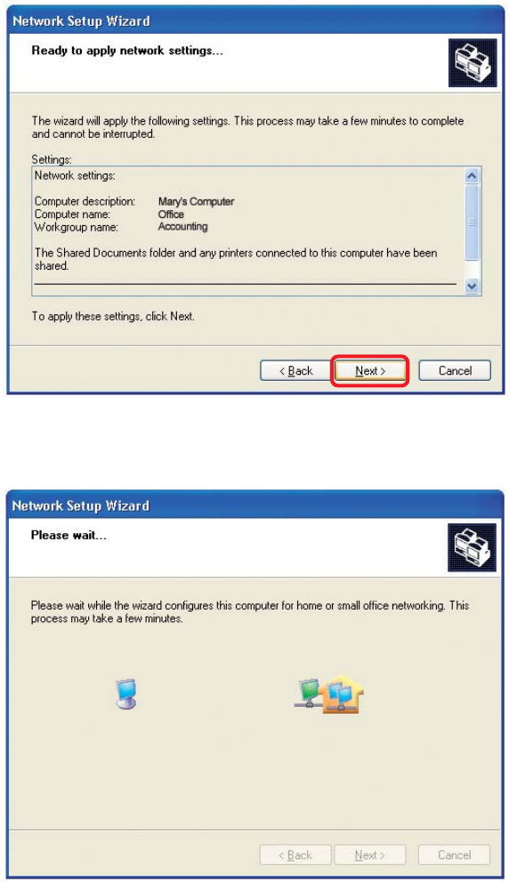
Please wait while the Network Setup Wizard applies the changes.
Networking Basics
When the changes are complete, click Next.
Please wait while the Network Setup Wizard configures the computer.
This may take a few minutes.