D Link DVA-G3672B Wireless ADSL VOIP Router User Manual D Link DVA G3672B
D Link Corporation Wireless ADSL VOIP Router D Link DVA G3672B
D Link >
Contents
- 1. User manual 1
- 2. Users Manual 2
- 3. Users Manual 3
Users Manual 3
Chapter 2 Configuration
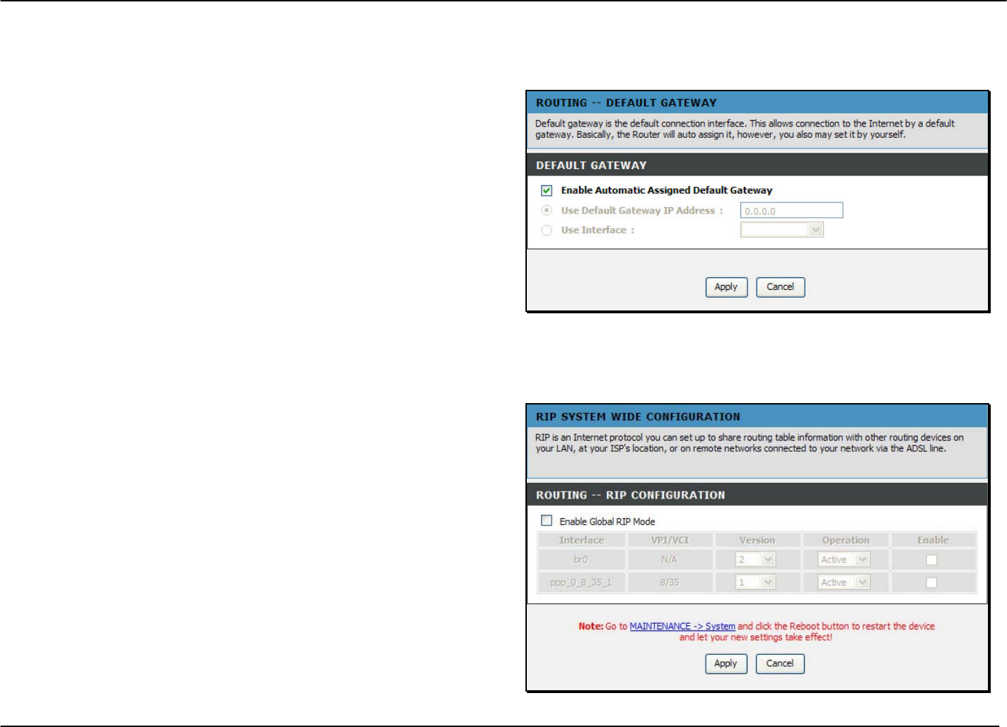
Routing – Default Gateway
To access Default Gateway, point to the Routing on the left window and click Default Gateway submenu, or click the Default
Gateway button in the Routing window.
This page can either automatically assign a default gateway to
the device or manually type in a default gateway or the device
or interface. It is recommended to leave Enable Automatic
Assigned Default Gateway ticked to automatically detect the
Gateway IP address.
Routing – RIP
To access RIP, point to the Routing on the left window and click RIP submenu, or click the RIP button in the Routing window.
The Router supports RIP version 1 and 2 used to share routing
tables with other Layer 3 routing devices on your local network
or remote LAN. The Operation setting refers to the RIP request.
Select Active to allow RIP requests from other devices. Select
Passive to instruct the Router to make RIP requests for routing
tables from other devices.
To enable RIP, tick the Enable Global RTP Mode check box,
select the Version (1, 2, or Both) and Operation (Active or
Passive), and tick the Enable check box in the corresponding
entry. Click the Apply button. Go to Maintenance -> System
and click Reboot to restart the device and let your changes
take effect.
D-Link DVA-G3672B User Manual 56
Chapter 2 Configuration
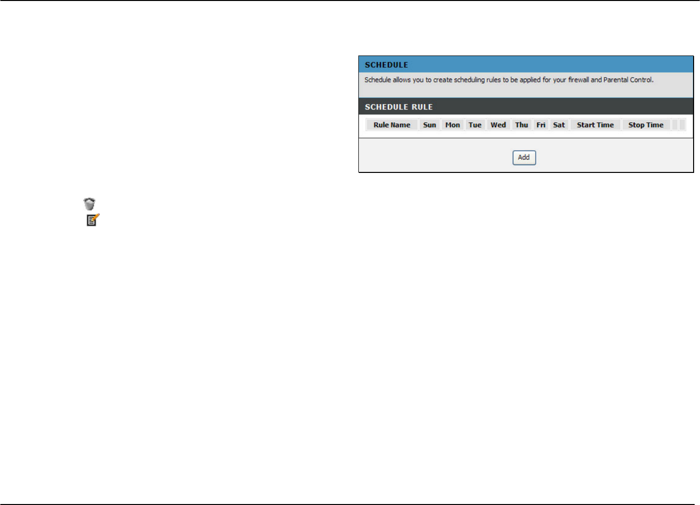
Advanced – Schedules
To access the Schedules window, click the schedules button in the Advanced directory.
You can add schedules in this page and then apply them to
Parental Control.
Click Add to see the Add Schedule Rule section. Enter a Name
for the schedule. Use the radio buttons to click the desired
Day(s), either All Week or Select Day(s) (in which case you
must tick the checkboxes for the desired individual days of the
week), select the desired Start Time and End Time or tick the
All Day – 24 hrs checkbox. Click Apply to see the entry in the
Schedule Rule table. To remove an entry in the table, click the
corresponding button. To modify a table entry, click the
corresponding button, make the desired changes, and then
click the Apply button.
D-Link DVA-G3672B User Manual 57
Chapter 2 Configuration
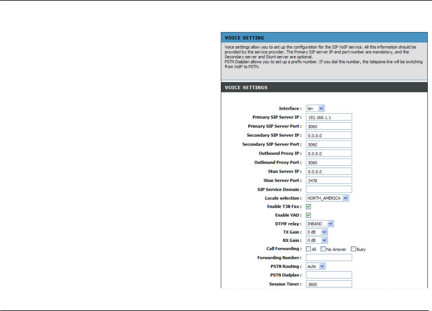
Advanced – Voice
To access the Voice window, click the Voice button in the Advanced directory.
You can set up the basic VoIP settings in this page. All
information in this page should be obtained by your ISP.
Voice over Internet Protocol (VoIP) is a protocol that can
transmit the voice through the Internet. Session Initiation
Protocol (SIP) is a widely used signaling protocol of VoIP. To
start using the VoIP service, select an interface in the Interface
list for the VoIP service, and enter the Primary SIP Server IP
and Primary SIP Server Port. The Secondary SIP Server,
Outbound Proxy IP, Stun Server and SIP Service Domain are
optional. Tick Enable T38 Fax for sending fax data through the
network. Tick Enable VAD to disable silent packet and send
other transmission. Select a DTMF type (Inband, RFC2833 or
SIP Info) in the DTMF relay drop-down list. Tick one of
forwarding call methods for All, No Answer or Busy calls, and
then type a number that calls is forwarded to. Select a routing
rule of the PSTN line (auto, Line1 or Line2) in the PSTN
Routing drop-down list. Enter digits in the PSTN Dialplan field
for transferring VoIP service to PSTN service.
You can also set up the codec priorities in Codec Settings
section. In VoIP Setting section, you can configure the user
name and password for registering to SIP VoIP service.
Click the Apply button, and go to Maintenance -> System and click
Reboot to restart the device and let your changes take effect.
D-Link DVA-G3672B User Manual 58
Chapter 2 Configuration
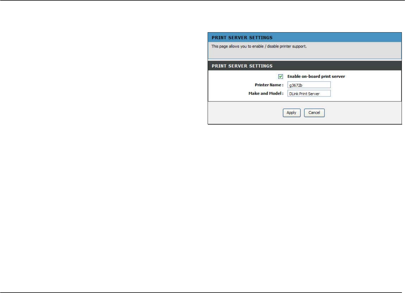
Advanced –Print Server
To access the Print Server window, click the Print Server button in the Advanced directory.
Tick the Enable on-board print server check box, enter a
Printer Name and Model name in the fields, and click Apply to
enable the printer server function.
D-Link DVA-G3672B User Manual 59
Chapter 2 Configuration
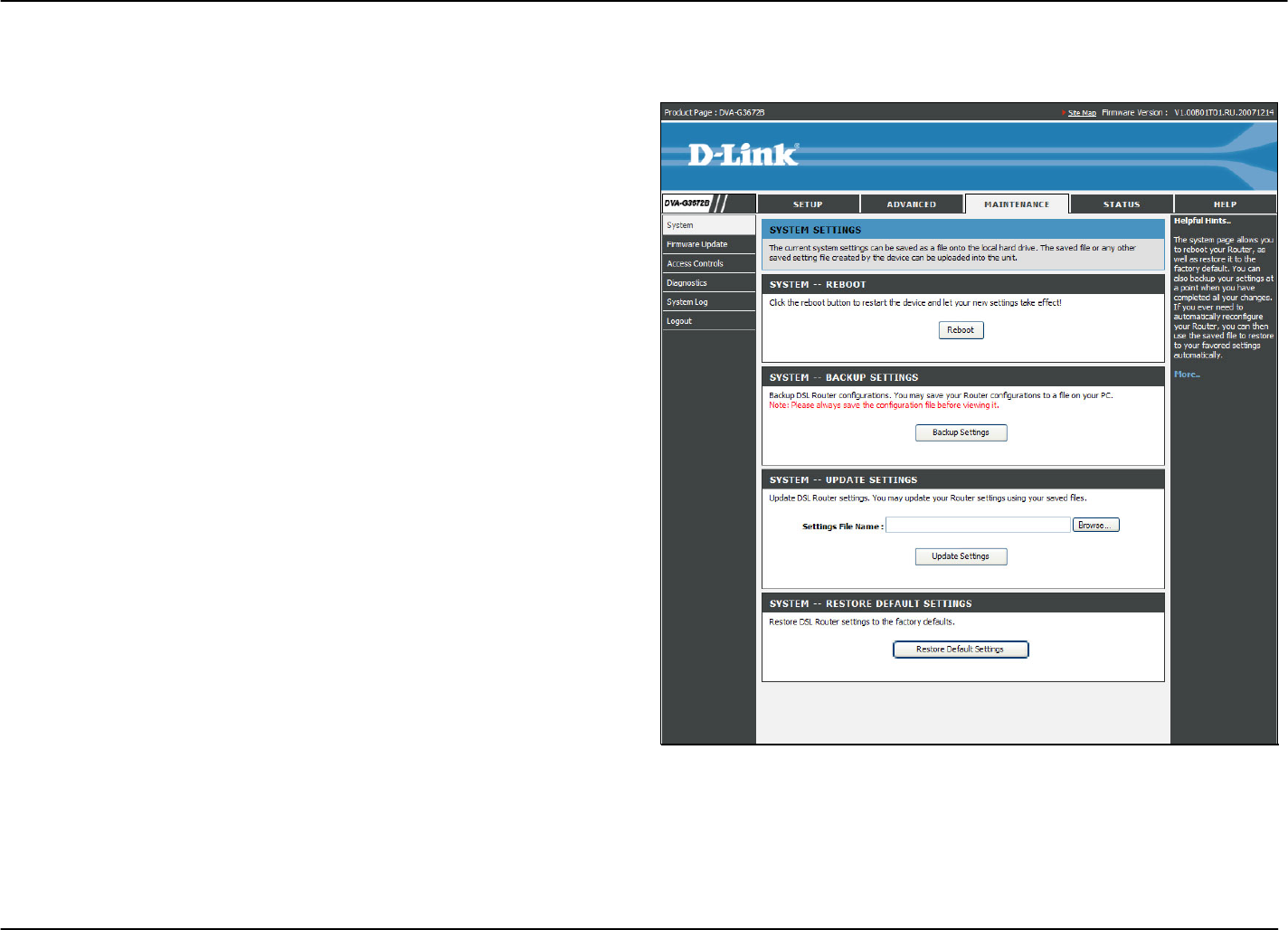
Maintenance – System
To access the System window, click the System button in the Maintenance directory.
When you configure the Router, you will need to restart the
Router to take the settings effect. Click Reboot to restart the
Router.
Once you have configured the Router to your satisfaction, it is a
good idea to back up the configuration file to your computer. To
save the current configuration settings to your computer, click
the Backup Settings button. You will be prompted to select a
location on your computer to put the file. The file type is bin and
may be named anything you wish.
To load a previously saved configuration file, click the Browse
button and locate the file on your computer. Click the Upload
Settings button to load the settings from your local hard drive.
Confirm that you want to load the file when prompted. The
Router will reboot and begin operating with the configuration
settings that have just been loaded.
To reset the Router to its factory default settings, click the
Restore Default Settings button. You will be prompted to
confirm your decision to reset the Router. The Router will
reboot with the factory default settings including IP settings
(192.168.1.1) and Administrator password (admin).
D-Link DVA-G3672B User Manual 60
Chapter 2 Configuration
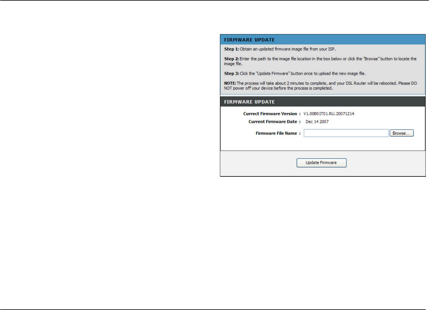
Maintenance – Firmware Update
To access the Firmware Update window, click the Firmware Update button in the Maintenance directory.
Use the Firmware Upgrade menu to load the latest firmware for
the Router. Note that the Router configuration settings may
return to the factory default settings, so make sure you save the
configuration settings with the System menu described above.
To upgrade firmware obtained from your ISP, click the Browse
button to search for the file. Click the Update Firmware button
to begin copying the file. The file will load and restart the Router
automatically.
D-Link DVA-G3672B User Manual 61
Chapter 2 Configuration
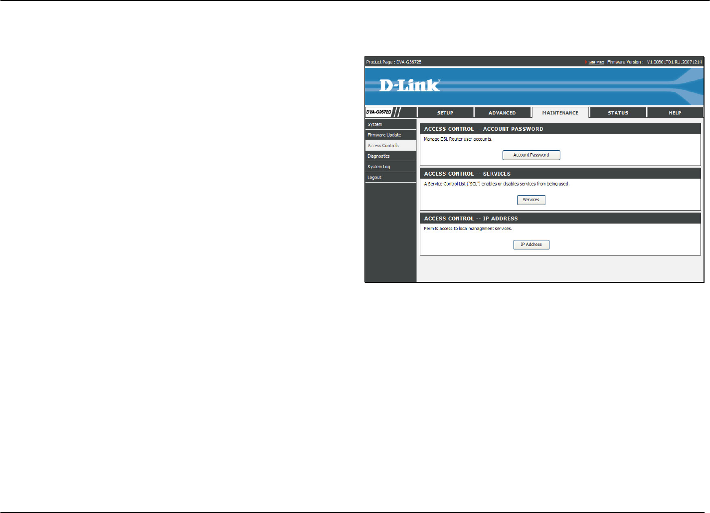
Maintenance – Access Controls
To access the Access Controls window, click the Access Controls button in the Maintenance directory.
In this page, you can choose to change password, manage the
service control or IP address control.
D-Link DVA-G3672B User Manual 62
Chapter 2 Configuration
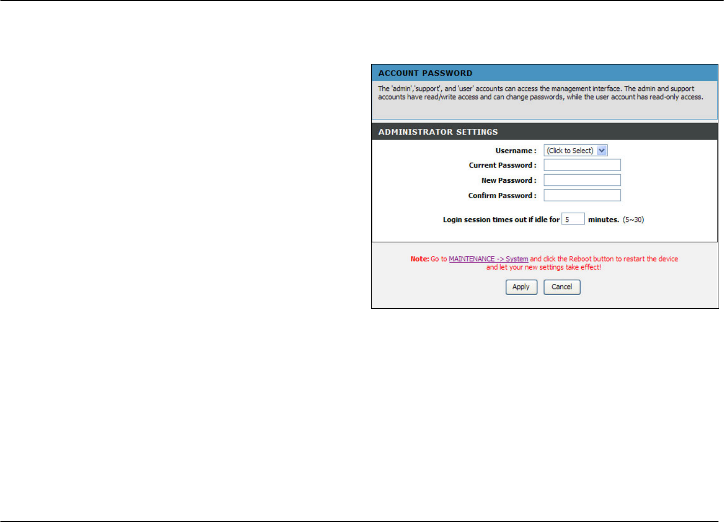
Access Controls – Account Password
To access Account Password, point to the Access Controls on the left window and click Account Password submenu, or click the
Account Password button in the Access Controls window.
There are three different user names for different purpose.
Support is for remote supporter to login from WAN and is able
to adjust TR-069 settings. User and Admin is to login from LAN.
Select a user name (Admin, User or Support), type the Current
Password in the first field, the New Password in the second
field, and enter the password again in the Confirm Password
field to be certain you have typed it correctly.
You can configure the idle time between 5 and 30 minutes for
the webpage asking you to logout.
Click the Apply button. Go to Maintenance -> System and
click Reboot to restart the device.
D-Link DVA-G3672B User Manual 63
Chapter 2 Configuration
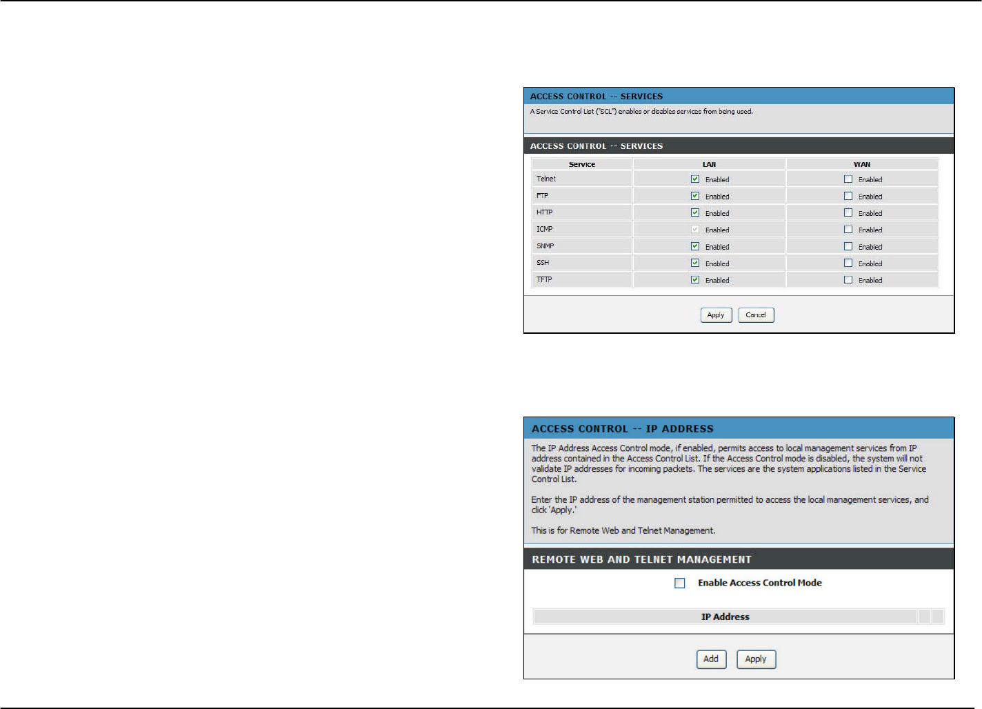
Access Controls – Services
To access Services, point to the Access Controls on the left window and click Services submenu, or click the Services button in
the Access Controls window.
This page lists out all the available services including Telnet,
FTP, HTTP, ICMP, SNMP, SSH and TFTP that can enable at
LAN, WAN or both. Tick to enable the services, or deselect to
disable them.
Access Controls – IP Address
To access IP Address, point to the Access Controls on the left window and click IP Address submenu, or click the IP Address
button in the Access Controls window.
Click Add to see the Add IP Address section. Enter an IP
address and click Apply in the section. The IP address will
show in the table in the Remote Web and Telnet Management
section. Tick the Enable Access Control Mode check box and
click Apply in this section to enable the function.
D-Link DVA-G3672B User Manual 64
Chapter 2 Configuration
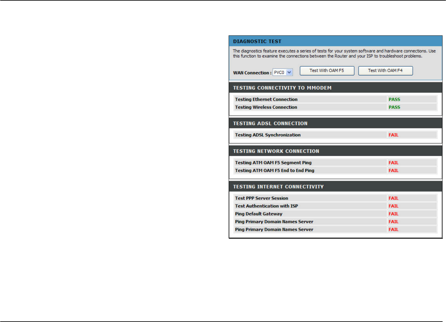
Maintenance – Diagnostics
To access the Diagnostics window, click the Diagnostics button in the Maintenance directory.
This window is used to test connectivity of the Router. A Ping
test may be done through the local or external interface to test
connectivity to known IP addresses. The diagnostics feature
executes a series of tests of your system software and
hardware connections. Use this window when working with your
ISP to troubleshoot problems.
D-Link DVA-G3672B User Manual 65
Chapter 2 Configuration
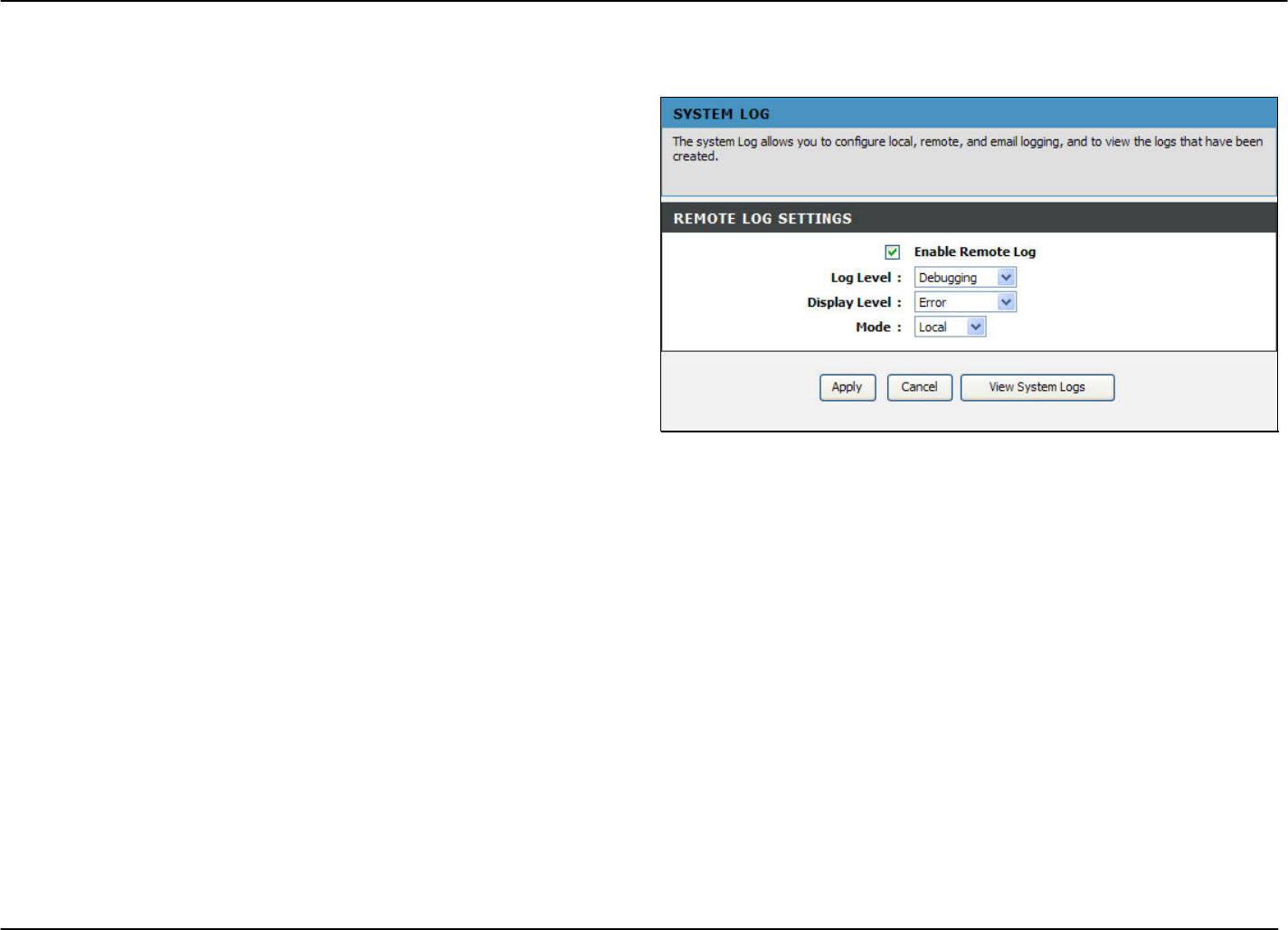
Maintenance – System Log
To access the System Log window, click the System Log button in the Maintenance directory.
The system log allows you to configure local and remote
logging, and to view the logs that have been created.
To generate a system log, tick the Enable Remote Log check
box. Select the Log Level and Display Level from the drop-
down lists. The levels available are the same for each type of
level: Emergency, Alert, Critical, Error, Warning, Notice,
Informational and Debugging. Click the Apply button to allow
your new settings to take effect.
D-Link DVA-G3672B User Manual 66
Chapter 2 Configuration
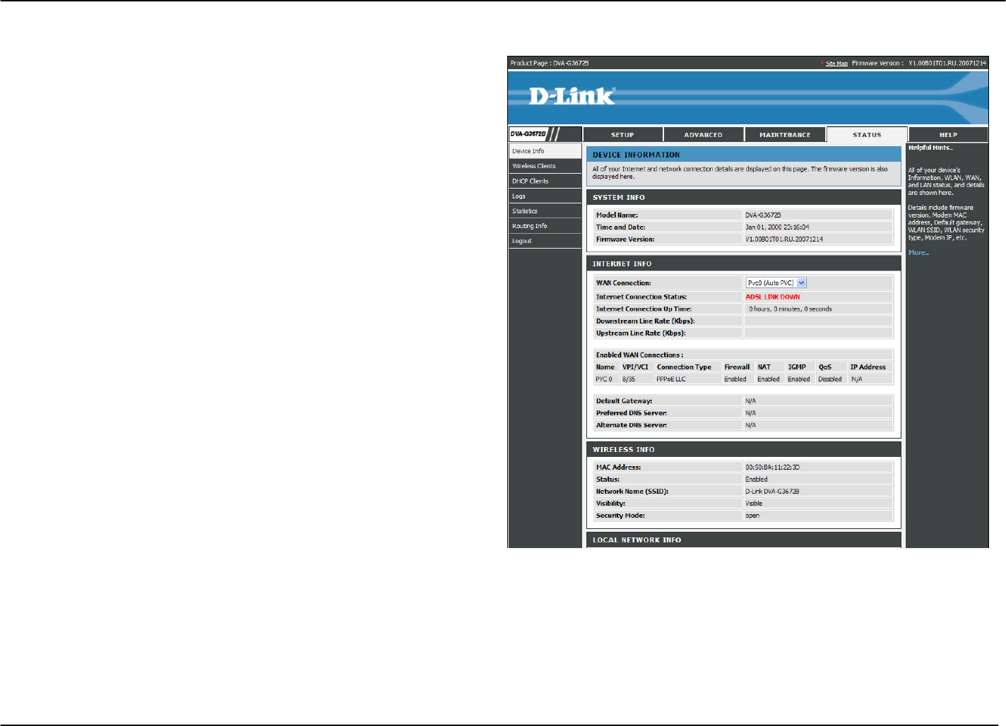
Status – Device Info
Use the Device Information window to quickly view basic
current information about the Wireless, WAN and local
network interfaces, and device information including Model
Name, Time and Date, and Firmware.
D-Link DVA-G3672B User Manual 67
Chapter 2 Configuration
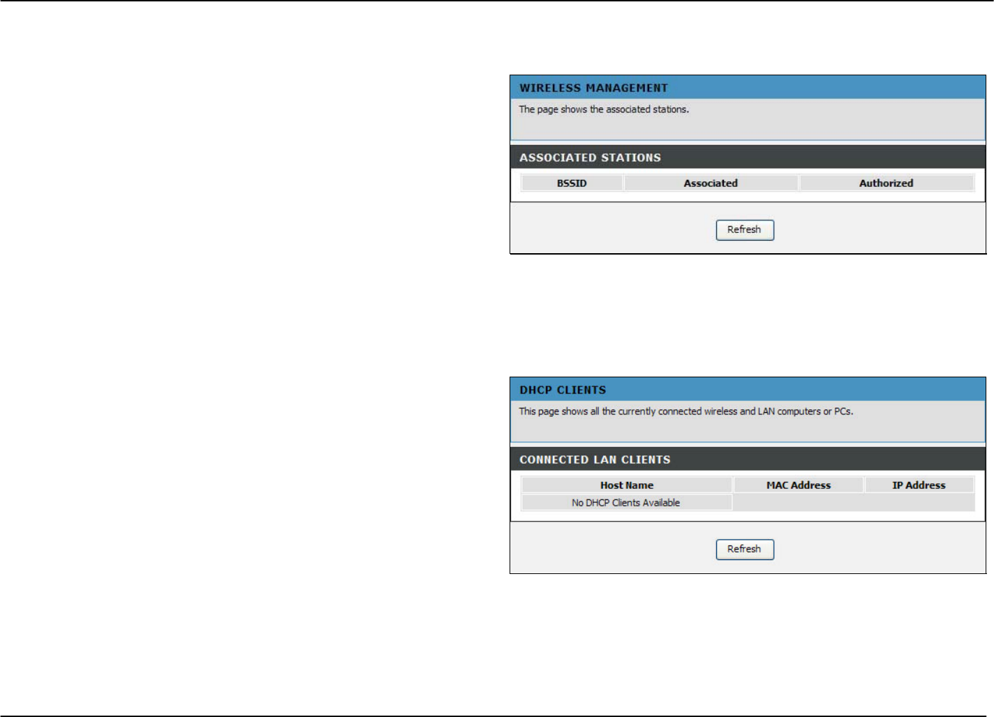
Status – Wireless Clients
To access the Wireless Clients window, click the Wireless Clients button in the Status directory.
The Wireless Clients window lists out the active Wireless
connection when the Wireless function is on.
Status – DHCP Clients
To access the DHCP Clients window, click the DHCP Clients button in the Status directory.
The Connected LAN Clients list displays active DHCP clients
when the Router is acting as a DHCP server.
D-Link DVA-G3672B User Manual 68
Chapter 2 Configuration
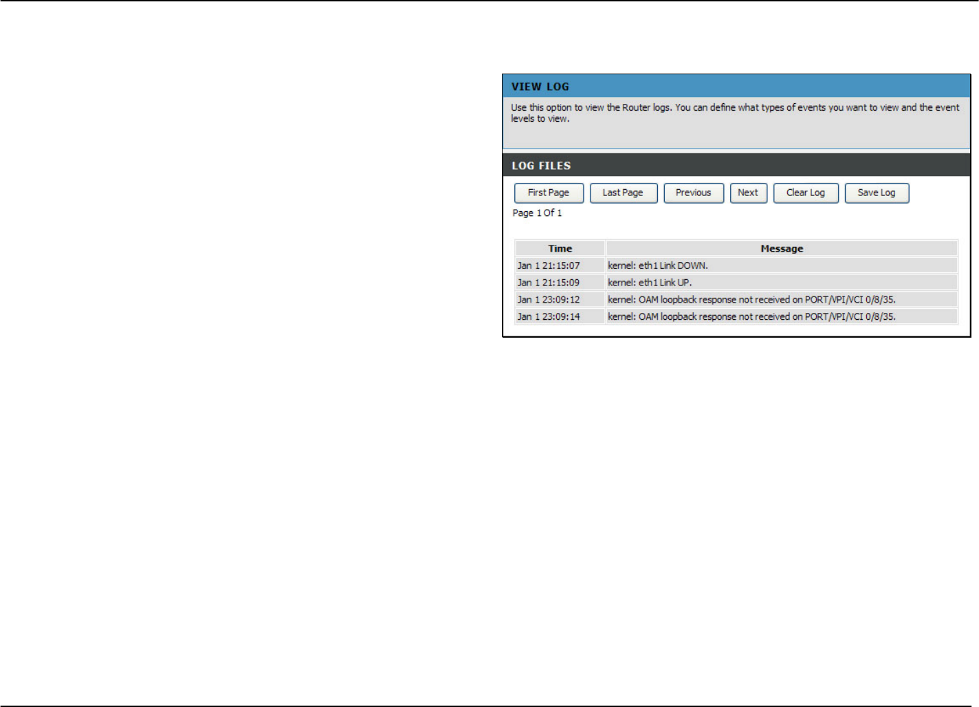
Status – Logs
To access the Logs window, click the Logs button in the Status directory.
This page displays the event logs of the Router. Click Clear
Log to delete all the records. Click Save Log to save the
records as a *.sys file.
D-Link DVA-G3672B User Manual 69
Chapter 2 Configuration
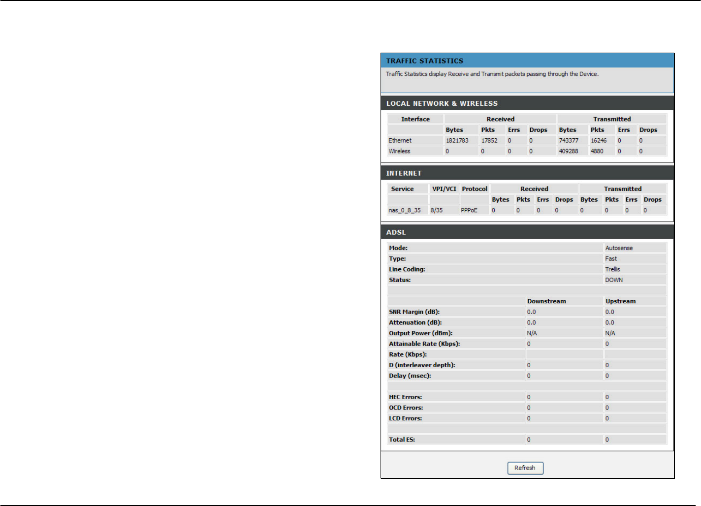
Status – Statistics
To access the Statistics window, click the Statistics button in the Status directory.
Use this window to monitor traffic on the Local Network &
Wireless, Internet or ADSL connections. This window also
displays information concerning ADSL status.
D-Link DVA-G3672B User Manual 70
Chapter 2 Configuration
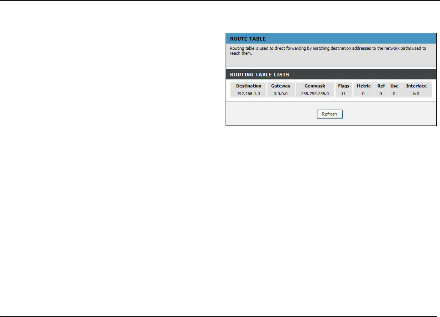
Status – Routing Info
To access the Routing Info window, click the Routing Info button in the Status directory.
This page displays all the routing rules information.
D-Link DVA-G3672B User Manual 71
Chapter 2 Configuration
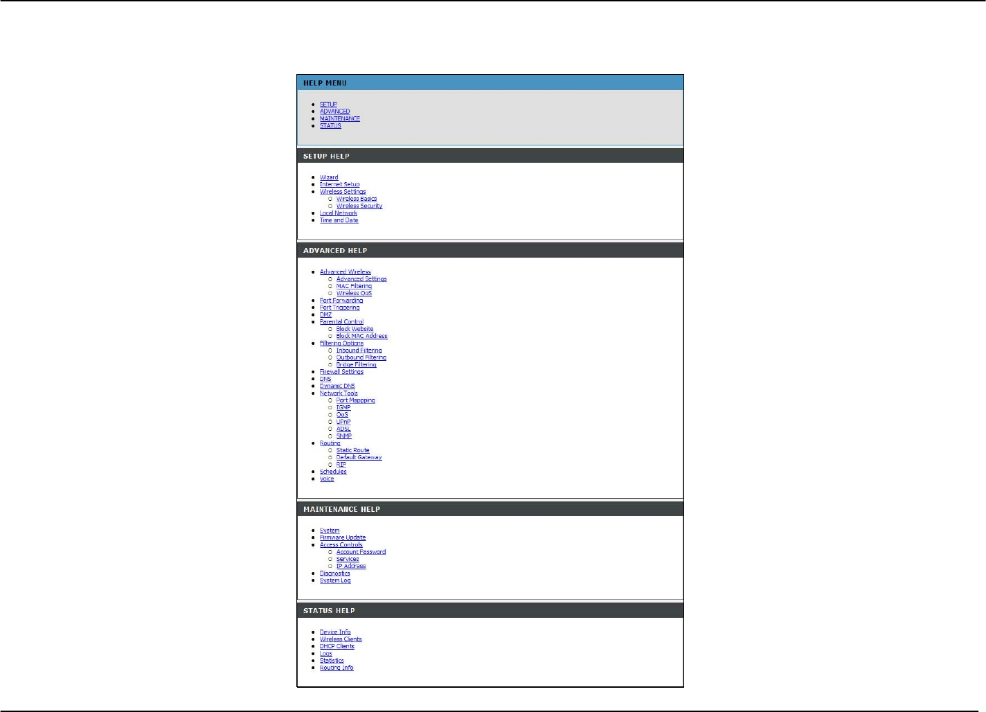
Help
To access the Help window, click the Help directory.
D-Link DVA-G3672B User Manual 72
FCC Notices
This device complies with Part 15 of the FCC Rules. Operation is subject to the following
two conditions: (1) this device may not cause harmful interference, and (2) this device
must accept any interference received, including interference that may cause undesired
operation.
CAUTION: Change or modification not expressly approved by the party responsible
for compliance could void the user’s authority to operate this equipment.
This equipment has been tested and found to comply with the limits for a Class B
digital device, pursuant to Part 15 of the FCC Rules. These limits are designed to provide
reasonable protection against harmful interference in a residential installation. This
equipment generates, uses and can radiate radio frequency energy and, if not installed
and used in accordance with the instructions, may cause harmful interference to radio
communications. However, there is no guarantee that interference will not occur in a
particular installation. If this equipment does cause harmful interference to radio or
television reception, which can be determined by turning the equipment off and on, the
user is encouraged to try to correct the interference by one or more of the following
measures:
--Reorient or relocate the receiving antenna.
--Increase the separation between the equipment and receiver.
--Connect the equipment into an outlet on a circuit different from that to which the receiver
is connected.
--Consult the dealer or an experienced radio/TV technician for help.
CAUTION:
Any changes or modifications not expressly approved by the grantee of this device could
void the user's authority to operate the equipment.
RF exposure warning
This equipment must be installed and operated in accordance with provided instructions
and the antenna(s) used for this transmitter must be installed to provide a separation
distance of at least 20 cm from all persons and must not be co-located or operating in
conjunction with any other antenna or transmitter. End-users and installers must be
provide with antenna installation instructions and transmitter operating conditions for
satisfying RF exposure compliance."