D Link I524I1 Wireless 150 Router User Manual I
D Link Corporation Wireless 150 Router I
UserManual.wiki
>
D Link
>
I524I1 User Manual
>
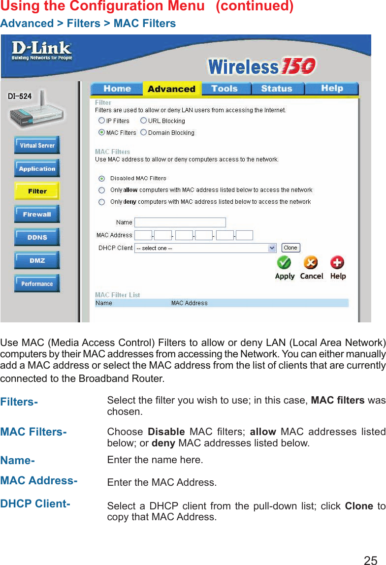
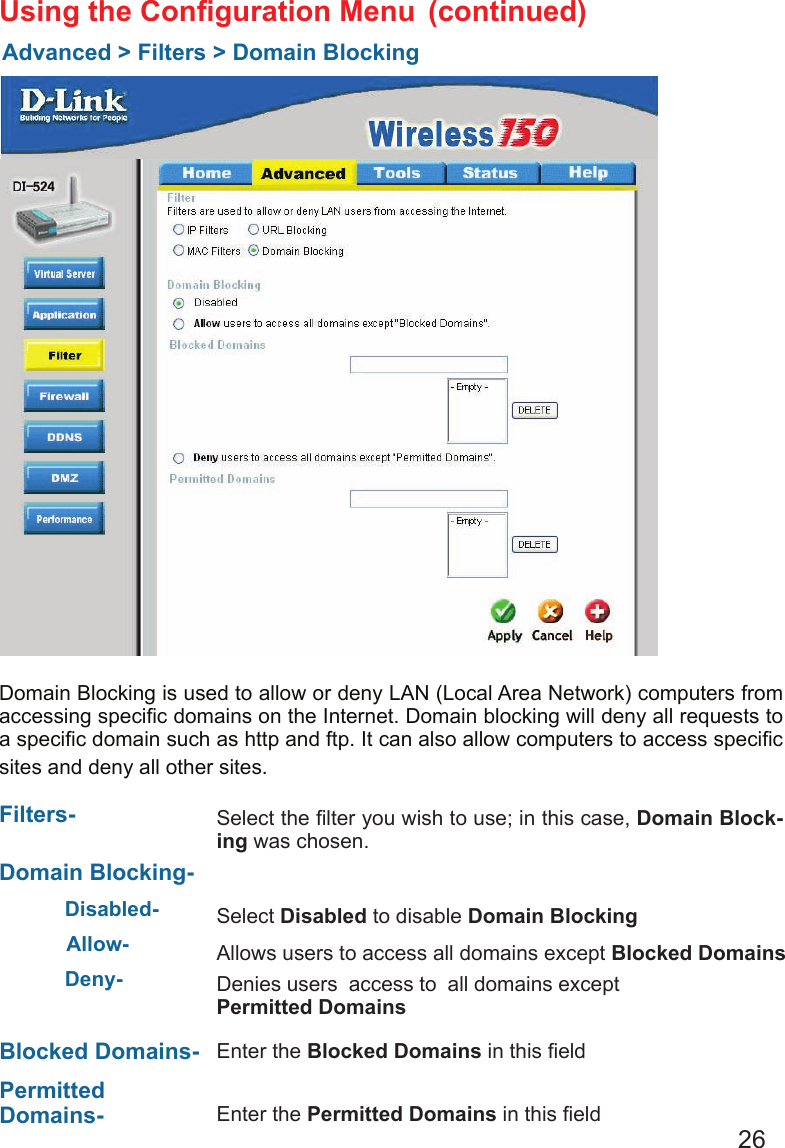
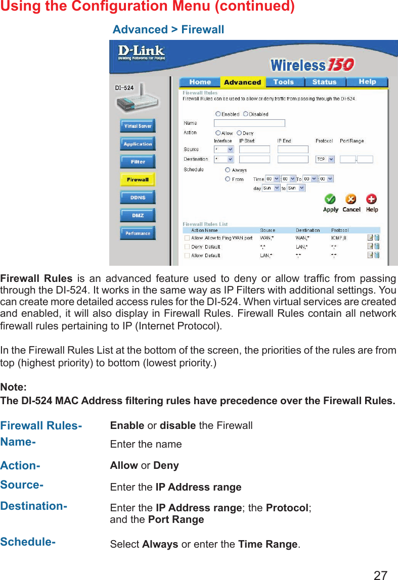
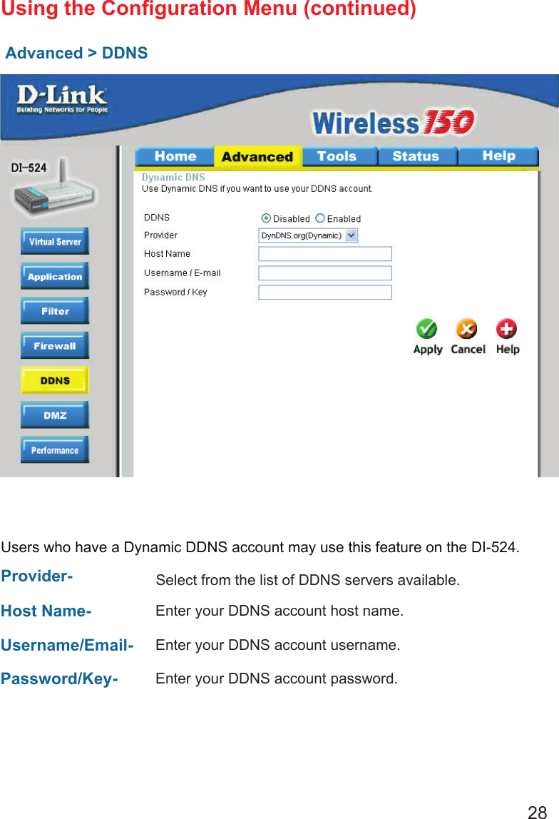
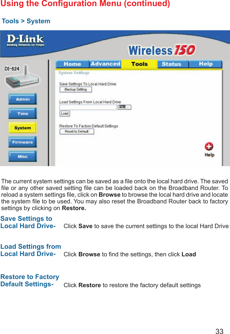
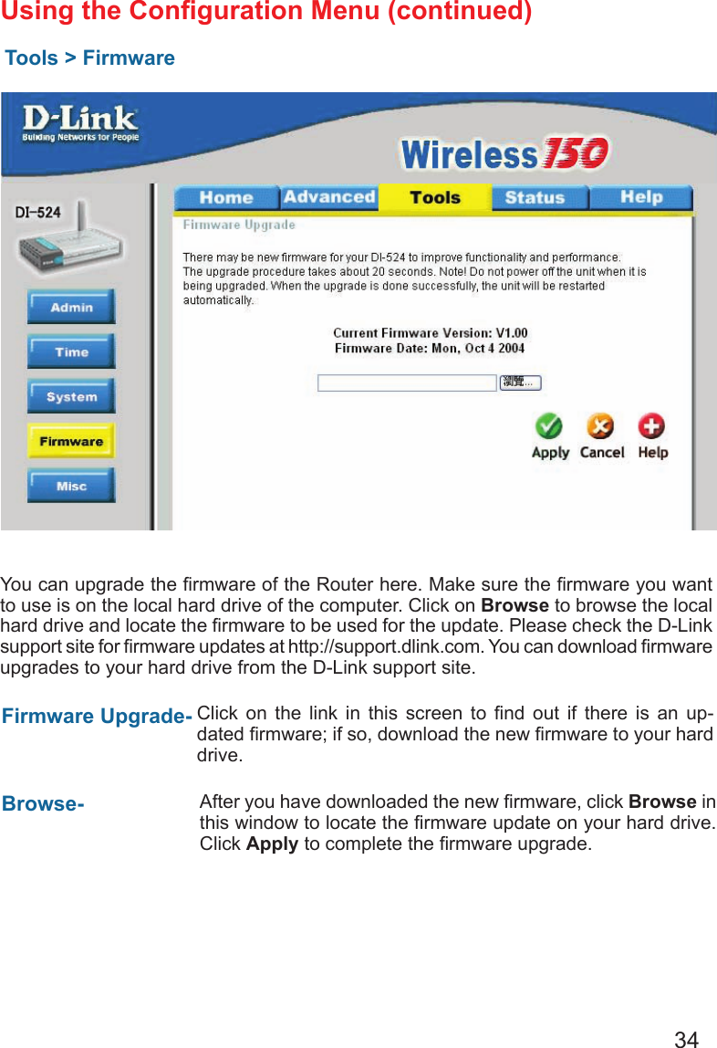
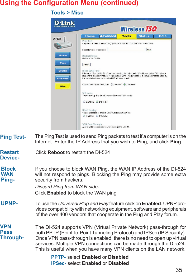
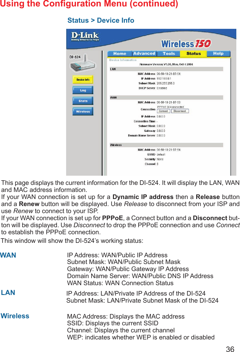
user manual I
Contents
1.
user manual I
2.
user manual II
user manual I
Navigation menu
Upload a User Manual
Namespaces
Wiki Guide
HTML
PDF
Info
Views
User Manual
Discussion / Help
Navigation