Contents
- 1. user manual I
- 2. user manual II
user manual I

Manual
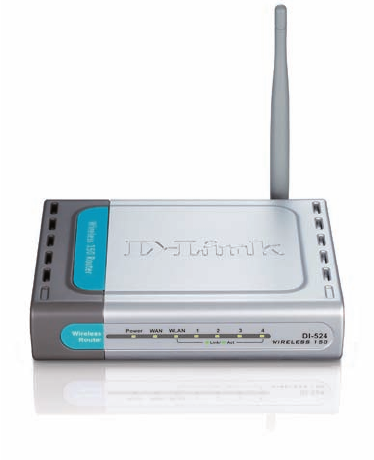
Wireless Router
DI-524
2
Contents
Package Contents ................................................................................ 3
Introduction ........................................................................................... 4
Wireless Basics .................................................................................... 8
Getting Started ....................................................................................11
Using the Conguration Menu ............................................................ 12
Networking Basics .............................................................................. 40
Troubleshooting .................................................................................. 55
Technical Specications ..................................................................... 62
Frequently Asked Questions............................................................... 65
3
Internet Explorer Version 6.0 or Netscape Navigator Version 7.0
and Above
Contents of Package:
D-Link DI-524 Wireless 150 Router
Switching 5V/1A Full-Range
Manual and Warranty on CD
Quick Installation Guide
Ethernet Cable (All the DI-524’s Ethernet ports are Auto-MDIX)
Computers with Windows, Macintosh, or Linux-based
operating systems with an installed Ethernet adapter
Package Contents
Note: Using a power supply with a different voltage rating than the one included with
the DI-524 will cause damage and void the warranty for this product.
If any of the above items are missing, please contact your reseller.
System Requirements for Conguration:
Ethernet-Based Cable or DSL Modem
4
Introduction
The D-Link DI-524 is based on 802.11n technology, wireless router that supports high-
speed wireless networking at home, at work or in public places.
Unlike most routers, the DI-524 provides data transfers at up to 150 Mbps (compared to
the standard 54 Mbps) when used with other D-Link N products. The 802.11g standard
is backwards compatible with 802.11b products. This means that you do not need to
change your entire network to maintain connectivity. You may sacrice some of 802.11g’s
speed when you mix 802.11b and 802.11g devices, but you will not lose the ability to
communicate when you incorporate the 802.11g standard into your 802.11b network.
You may choose to slowly change your network by gradually replacing the 802.11b
devices with 802.11g devices .
In addition to offering faster data transfer speeds when used with other 802.11g products,
the DI-524 has the newest, strongest, most advanced security features available today.
When used with other 802.11g WPA (WiFi Protected Access) and 802.1x compatible
products in a network with a RADIUS server, the security features include:
WPA: Wi-Fi Protected Access authorizes and identies users based on a secret key
that changes automatically at a regular interval. WPA uses TKIP (Temporal
Key Integrity Protocol) to change the temporal key every 10,000 packets (a
packet is a kind of message transmitted over a network.) This insures much
greater security than the standard WEP security. (By contrast, the older WEP
encryption required the keys to be changed manually.)
802.1x: Authentication is a rst line of defense against intrusion. In the Authentication
process the server veries the identity of the client attempting to connect to the
network. Unfamiliar clients would be denied access.
For home users that will not incorporate a RADIUS server in their network, the security
for the DI-524, used in conjunction with other 802.11g products, will still be much stronger
than ever before. Utilizing the Pre Shared Key mode of WPA, the DI-524 will obtain a
new security key every time it connects to the 802.11g network. You only need to input
your encryption information once in the conguration menu. No longer will you have to
manually input a new WEP key frequently to ensure security, with the DI-524, you will
automatically receive a new key every time you connect, vastly increasing the safety
of your communications.
5
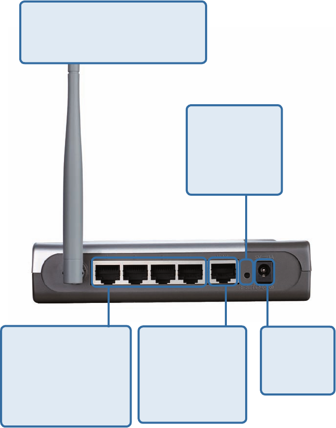
Connections
All Ethernet Ports (WAN and LAN)
are auto MDI/MDIX, meaning you
can use either a straight-through or
a crossover Ethernet cable.
The Auto MDI/
MDIX WAN port is
the connection for
the Ethernet cable
to the Cable or
DSL modem
Auto MDI/MDIX
LAN ports
automatically sense
the cable type
when connecting to
Ethernet-enabled
computers.
Receptor
for the
Power
Adapter
Pressing the
Reset Button
restores the
router to its
original factory
default settings.
6
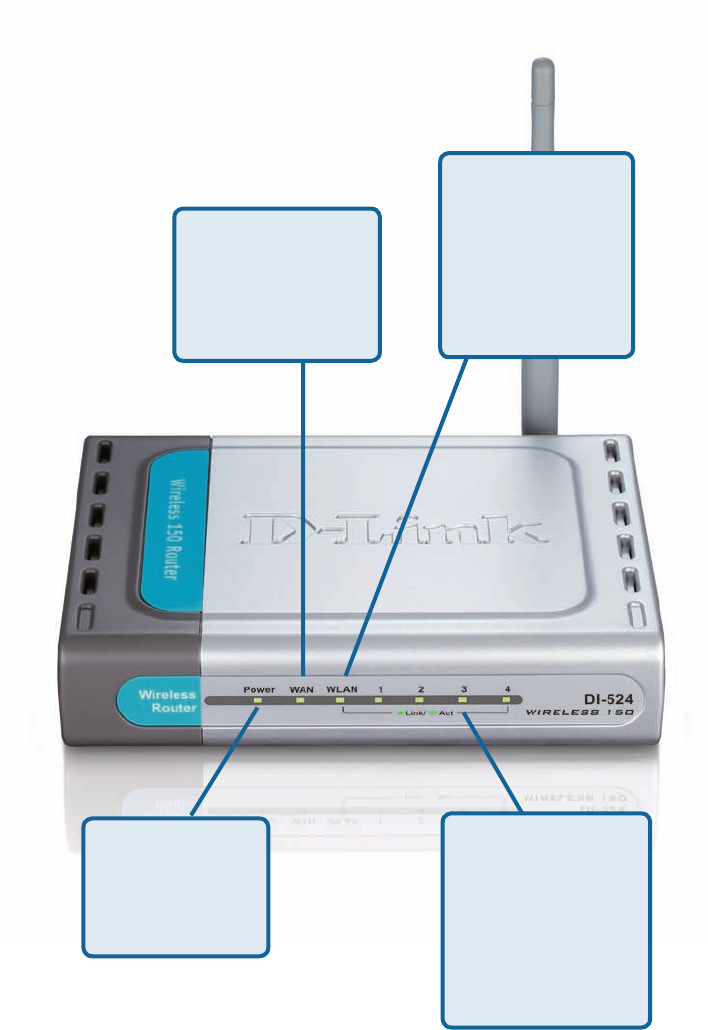
LEDs
WLAN LED
A solid light
indicates that the
wireless segment
is ready. This
LED blinks during
wireless data
transmission
POWER LED
A solid light
indicates a proper
connection to the
power supply
LOCAL
NETWORK LED
A solid light indicates
a connection to an
Ethernet-enabled
computer on ports
1-4. This LED
blinks during data
transmission
WAN LED
A solid light indicates
connection on the
WAN port. This LED
blinks during data
transmission
7
Features
WPA (Wi Fi Protected Access) authorizes and identies users based on a
secret key that changes automatically at a regular interval, for example:
802.1x Authentication in conjunction with the RADIUS server veries the
identity of would be clients
TKIP (Temporal Key Integrity Protocol), in conjunction with a RADIUS
server, changes the temporal key every 10,000 packets, ensuring
greater security
Pre Shared Key mode means that the home user, without a RADIUS
server, will obtain a new security key every time the he or she connects
to the network, vastly improving the safety of communications on the
network.
Backwards compatible with the 802.11b standard to provide a wireless data
rate of up to 11Mbps
Fully compatible with the 802.11g standard to provide a wireless data rate of
up to 54Mbps
Utilizes OFDM technology (Orthogonal Frequency Division Multiplexing)
User-friendly conguration and diagnostic utilities
Operates in the 2.4GHz frequency range
Connects multiple computers to a Broadband (Cable or DSL) modem to
share the Internet connection
IP Filtering
Advanced Firewall features
DHCP server supported enables all networked computers to automatically
receive IP addresses
Web-based interface for Managing and Conguring
Access Control to manage users on the network
Supports special applications that require multiple connections
Equipped with 4 10/100 Ethernet ports, 1 WAN port, Auto MDI/MDIX
URL Filtering
Domain Blocking
Scheduling
Supports NAT with VPN pass-through, providing added security
MAC Filtering
8
Wireless Basics
D-Link wireless products are based on industry standards to provide easy-to-use and
compatible high-speed wireless connectivity within your home, business or public
access wireless networks. D-Link wireless products will allow you access to the data
you want, when and where you want it. You will be able to enjoy the freedom that
wireless networking brings.
A WLAN is a cellular computer network that transmits and receives data with radio signals
instead of wires. WLANs are used increasingly in both home and ofce environments,
and public areas such as airports, coffee shops and universities. Innovative ways to
utilize WLAN technology are helping people to work and communicate more efciently.
Increased mobility and the absence of cabling and other xed infrastructure have proven
to be benecial for many users.
Wireless users can use the same applications they use on a wired network. Wireless
adapter cards used on laptop and desktop systems support the same protocols as
Ethernet adapter cards.
People use wireless LAN technology for many different purposes:
Mobility - Productivity increases when people have access to data in any location
within the operating range of the WLAN. Management decisions based on real-time
information can signicantly improve worker efciency.
Low Implementation Costs – WLANs are easy to set up, manage, change
and relocate. Networks that frequently change can benet from WLANs ease of
implementation. WLANs can operate in locations where installation of wiring may be
impractical.
Installation and Network Expansion - Installing a WLAN system can be fast and
easy and can eliminate the need to pull cable through walls and ceilings. Wireless
technology allows the network to go where wires cannot go - even outside the home
or ofce.
Scalability – WLANs can be congured in a variety of topologies to meet the needs
of specic applications and installations. Congurations are easily changed and range
from peer-to-peer networks suitable for a small number of users to larger infrastructure
networks to accommodate hundreds or thousands of users, depending on the number
of wireless devices deployed.
Inexpensive Solution - Wireless network devices are as competitively priced as
conventional Ethernet network devices.
9
Standards-Based Technology
The DI-524 Wireless Broadband Router utilizes the new 802.11g standard.
The IEEE 802.11g standard is an extension of the 802.11b standard. It increases the
data rate up to 54 Mbps within the 2.4GHz band, utilizing OFDM technology.
This means that in most environments, within the specied range of this device, you
will be able to transfer large les quickly or even watch a movie in MPEG format over
your network without noticeable delays. This technology works by transmitting high-
speed digital data over a radio wave utilizing OFDM (Orthogonal Frequency Division
Multiplexing) technology. OFDM works by splitting the radio signal into multiple
smaller sub-signals that are then transmitted simultaneously at different frequencies
to the receiver. OFDM reduces the amount of crosstalk (interference) in signal
transmissions.
The DI-524 is backwards compatible with 802.11b devices. This means that if you have
an existing 802.11b network, the devices in that network will be compatible with 802.11g
devices at speeds of up to 11Mbps in the 2.4GHz range.
Wireless Basics (continued)
10
Wireless Basics (continued)
Installation Considerations
The DI-524 lets you access your network, using a wireless connection, from virtually
anywhere within its operating range. Keep in mind, however, that the number, thickness
and location of walls, ceilings, or other objects that the wireless signals must pass
through, may limit the range. Typical ranges vary depending on the types of materials
and background RF (radio frequency) noise in your home or business. The key to
maximizing wireless range is to follow these basic guidelines:
Keep the number of walls and ceilings between the DI-524 and other network
devices to a minimum - each wall or ceiling can reduce your D-Link wireless
product’s range from 3-90 feet (1-30 meters.) Position your devices so that
the number of walls or ceilings is minimized.
Be aware of the direct line between network devices. A wall that is 1.5 feet
thick (.5 meters), at a 45-degree angle appears to be almost 3 feet (1 meter)
thick. At a 2-degree angle it looks over 42 feet (14 meters) thick! Position
devices so that the signal will travel straight through a wall or ceiling (instead
of at an angle) for better reception.
Keep your product away (at least 3-6 feet or 1-2 meters) from electrical
devices or appliances that generate extreme RF noise.
Building Materials can impede the wireless signal - a solid metal door or
aluminum studs may have a negative effect on range. Try to position wireless
devices and computers with wireless adapters so that the signal passes
through drywall or open doorways and not other materials.
1
2
3
4
11
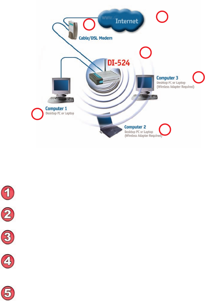
Please remember that wireless devices are pre-congured to connect together, right
out of the box, with their default settings.
You will need broadband Internet access (a Cable or DSL-subscriber line into
your home or ofce)
Consult with your Cable or DSL provider for proper installation of the modem
Connect the Cable or DSL modem to the DI-524 Wireless Broadband Router
(see the printed Quick Installation Guide included with your router.)
If you are connecting a desktop computer to your network, install the D-Link
DWA-125 wireless USB adapter into an available USB port on your desktop
computer. You may also install the DWA-140.
(See the printed Quick Installation Guide included with the network adapter.)
Getting Started
For a typical wireless setup at home (as shown above),
please do the following:
Setting up
a Wireless
Infrastructure
Network
1
2
3
4
Install the D-Link DFE-530TX+ adapter into a desktop computer. The four
Ethernet LAN ports of the DI-524 are Auto MDI/MDIX and will work with both
Straight-Through and Cross-Over cable.
(See the printed Quick Installation Guide included with the DFE-530TX+.)
6
5
12
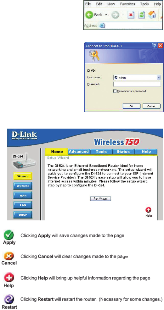
Type admin in the User
Name eld
Leave the Password blank
Click OK
Open the web browser
Type in the IP Address of
the Router (http://192.168.0.1)
Using the Conguration Menu
Home > Wizard
The Home>Wizard
screen will appear.
Please refer to the
Quick Installation
Guide for more
information regarding
the Setup Wizard.
Note: if you have changed the default IP Address assigned to
the DI-524, make sure to enter the correct IP Address.
These buttons
appear on most of the
conguration screens
in this section. Please
click on the appropriate
button at the bottom
of each screen after
you have made a
conguration change.
http://192.168.0.1
Whenever you want to congure your network or the
DI-524, you can access the Conguration Menu by
opening the web-browser and typing in the IP Address
of the DI-524. The DI-524 default IP Address is shown
at right: http://192.168.0.1
13
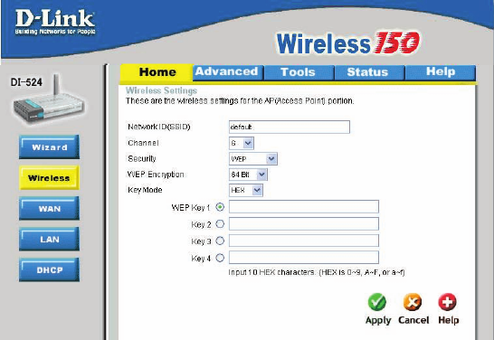
Using the Conguration Menu (continued)
Home > Wireless
Keys 1-4- Input up to 4 WEP keys; select the one you wish to use.
Key Mode- Select HEX or ASCII
WEP Encryption- Select the level of encryption desired: 64-bit, or 128-bit
Network ID(SSID)- Service Set Identier (SSID) is the name designated for a specic
wireless local area network (WLAN). The SSID’s factory default
setting is default. The SSID can be easily changed to connect
to an existing wireless network or to establish a new wireless
network.
Security- Select None, WEP, 802.1X, WPA-PSK or WPA. None is the
default setting. (Note: if you enable encryption on the DI-524,
please make sure that you also enable encryption on all the
wireless clients, or wireless connection will not be established.)
Channel- 6 is the default channel. All devices on the network must share
the same channel. (Note: The wireless adapters will automatically
scan and match the wireless setting.)
14
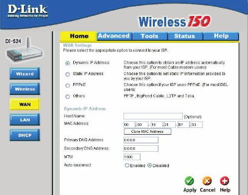
Using the Conguration Menu (continued)
Home > WAN > Dynamic IP Address
Host Name- The Host Name is optional but may be required by some ISPs.
The default host name is the device name of the Router and
may be changed.
MAC Address- The default MAC Address is set to the WAN’s physical interface
MAC address on the Broadband Router. It is not recommended
that you change the default MAC address unless required by
your ISP.
Clone
MAC Address-
The default MAC address is set to the WAN’s physical interface
MAC address on the Broadband Router. You can use the “Clone
MAC Address” button to copy the MAC address of the Ethernet
Card installed by your ISP and replace the WAN MAC address
with the MAC address of the router. It is not recommended
that you change the default MAC address unless required by
your ISP.
Dynamic
IP Address-
Choose Dynamic IP Address to obtain IP Address information
automatically from your ISP. Select this option if your ISP does
not give you any IP numbers to use. This option is commonly
used for Cable modem services.
Primary/
Secondary DNS
Address-
Enter an MTU value only if required by your ISP. Otherwise,
leave it a the default setting.
MTU-
Enter a DNS Address if you do not wish to use the one
provided by your ISP.
Select Enabled or Disabled.
Auto-reconnect-
15
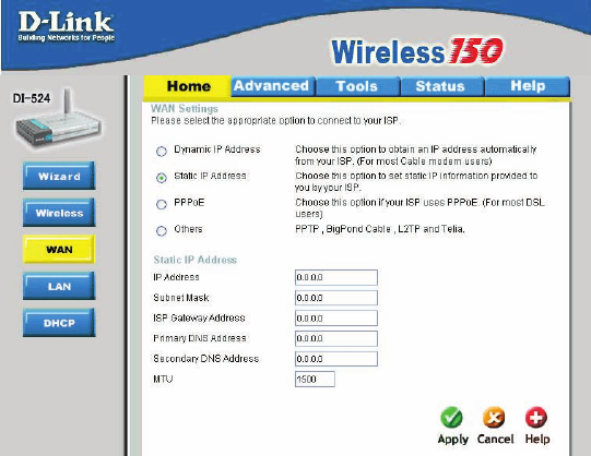
Home > WAN > Static IP Address
Static IP Address-
IP Address-
Subnet Mask-
ISP
Gateway Address-
Primary
DNS Address-
Secondary
DNS Address-
Choose Static IP Address if all WAN IP information is provided
to you by your ISP. You will need to enter in the IP address,
subnet mask, gateway address, and DNS address(es) provided
to you by your ISP. Each IP address entered in the elds must
be in the appropriate IP form, which are four octets separated
by a dot (x.x.x.x). The Router will not accept the IP address if
it is not in this format.
Input the public IP Address provided by your ISP
Input your Subnet mask. (All devices in the network must have
the same subnet mask.)
Input the public IP address of the ISP to which you are
connecting
Input the primary DNS (Domain Name Server) IP address
provided by your ISP
This is optional
Enter an MTU value only if required by your ISP. Otherwise,
leave it at the default setting.
MTU-
Using the Conguration Menu (continued)
16
Using the Conguration Menu (continued)
Home > WAN > PPPoE
IP Address- This option is only available for Static PPPoE. Enter the static
IP Address for the PPPoE connection.
(Continued on the next page)
User Name- Your PPPoE username provided by your ISP.
Service Name- Enter the Service Name provided by your ISP (optional).
Retype Password- Re-enter the PPPoE password
PPPoE-
Static PPPoE-you have an assigned (static) IP Address.
Choose this option if your ISP uses PPPoE. (Most DSL users
will select this option.)
Dynamic PPPoE- receive an IP Address automatically from your ISP.
Primary DNS
Address-
Primary DNS IP address provided by our ISP
Secondary DNS
Address-
This option is only available for Static PPPoE. Enter the static
IP Address for the PPPoE connection.
Choose PPPoE (Point
to Point Protocol over
Ethernet) if your
ISP uses a PPPoE
connection. Your
ISP will provide you
with a username and
password. This option
is typically used for
DSL services. Select
Dynamic PPPoE to
obtain an IP address
automatically for your
PPPoE connection.
Select Static PPPoE to
use a static IP address
for your PPPoeE
connection.
Please be sure
to remove any
existing PPPoE client
software installed on
your computers.
17
Using the Conguration Menu (continued)
Home > WAN > PPPoE continued
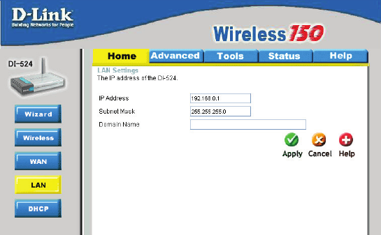
Home > LAN
LAN is short for Local Area Network. This is considered your internal network. These are
the IP settings of the LAN interface for the DI-524. These settings may be referred to as
Private settings. You may change the LAN IP address if needed. The LAN IP address
is private to your internal network and cannot be seen on the Internet.
Auto-reconnect- If enabled, the DI-524 will automatically connect to your ISP after
your system is restarted or if the PPPoE connection is dropped.
MTU- Maximum Transmission Unit-1492 is the default setting-you
may need to change the MTU for optimal performance with
your specic ISP.
Local Domain-Name- This eld is optional. Enter in the local domain name.
Subnet Mask- The subnet mask of the LAN interface.
The default subnet mask is 255.255.255.0
IP Address- The IP address of the LAN interface. The default IP address
is: 192.168.0.1
18
Using the Conguration Menu (continued)
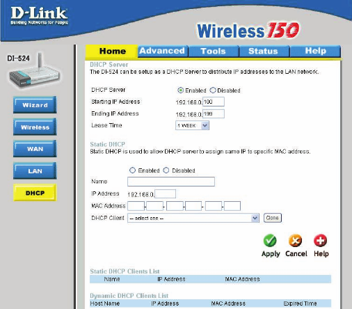
Home > DHCP
DHCP stands for Dynamic Host Control Protocol. The DI-524 has a built-in DHCP
server. The DHCP Server will automatically assign an IP address to the computers on
the LAN/private network. Be sure to set your computers to be DHCP clients by setting
their TCP/IP settings to “Obtain an IP Address Automatically.” When you turn your
computers on, they will automatically load the proper TCP/IP settings provided by the
DI-524. The DHCP Server will automatically allocate an unused IP address from the
IP address pool to the requesting computer. You must specify the starting and ending
address of the IP address pool.
DHCP Server- Select Enabled or Disabled. The default setting is Enabled.
Starting
IP Address-
The starting IP address for the DHCP server’s IP assignment
Ending
IP Address-
The ending IP address for the DHCP server’s IP assignment
Lease Time- The length of time for the IP lease. Enter the Lease time. The
default setting is one hour
19
Advanced > Virtual Server
Using the Conguration Menu (continued)
The DI-524 can be congured as a virtual server so that remote users accessing Web or
FTP services via the public IP address can be automatically redirected to local servers
in the LAN (Local Area Network).
The DI-524 rewall feature lters out unrecognized packets to protect your LAN network
so all computers networked with the DI-524 are invisible to the outside world. If you wish,
you can make some of the LAN computers accessible from the Internet by enabling Virtual
Server. Depending on the requested service, the DI-524 redirects the external service
request to the appropriate server within the LAN network.
The DI-524 is also capable of port-redirection meaning incoming trafc to a particular
port may be redirected to a different port on the server computer.
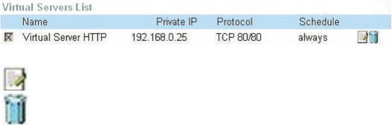
Each virtual service that is created will be listed at the bottom of the screen in the
Virtual Servers List. There are pre-dened virtual services already in the table. You
may use them by enabling them and assigning the server IP to use that particular
virtual service.
20
Advanced > Virtual Server continued
Using the Conguration Menu (continued)
Example #1:
Protocol Type- The protocol used for the virtual service
Public Port- The port number on the WAN (Wide Area Network) side that
will be used to access the virtual service.
Private Port- The port number of the service used by the Private IP
computer
Schedule- The schedule of time when the virtual service will be enabled.
The schedule may be set to Always, which will allow the
particular service to always be enabled. If it is set to Time,
select the time frame for the service to be enabled. If the
system time is outside of the scheduled time, the service will
be disabled.
Virtual Server- Select Enabled or Disabled
Name- Enter the name referencing the virtual service
Private IP- The server computer in the LAN (Local Area Network) that will
be providing the virtual services.
If you have a Web server that you wanted Internet users
to access at all times, you would need to enable it. Web
(HTTP) server is on LAN (Local Area Network) computer
192.168.0.25. HTTP uses port 80, TCP.
Name: Web Server
Private IP: 192.168.0.25
Protocol Type: TCP
Private Port: 80
Public Port: 80
Schedule: always
21
Example #2:
If you have an FTP server that you wanted Internet users to access by WAN port
2100 and only during the weekends, you would need to enable it as such. FTP
server is on LAN computer 192.168.0.30. FTP uses port 21, TCP.
Name: FTP Server
Private IP: 192.168.0.30
Protocol Type: TCP
Private Port: 21
Public Port: 2100
Schedule: From: 01:00AM to 01:00AM, Sat to Sun
Using the Conguration Menu (continued)
Advanced > Virtual Server continued
Click on this icon to edit the virtual service
Click on this icon to delete the virtual service
All Internet users who want to access this FTP Server
must connect to it from port 2100. This is an example of
port redirection and can be useful in cases where there
are many of the same servers on the LAN network.
22
Using the Conguration Menu (continued)
Advanced > Applications
Some applications require multiple connections, such as Internet gaming, video
conferencing, Internet telephony and others. These applications have difculties working
through NAT (Network Address Translation). Special Applications makes some of these
applications work with the DI-524. If you need to run applications that require multiple
connections, specify the port normally associated with an application in the “Trigger Port”
eld, select the protocol type as TCP or UDP, then enter the public ports associated
with the trigger port to open them for inbound trafc.
The DI-524 provides some predened applications in the table on the bottom of the
web page. Select the application you want to use and enable it.
Note! Only one PC can use each Special Application tunnel.
Name: This is the name referencing the special application.
Trigger Port: This is the port used to trigger the application. It can be either
a single port or a range of ports.
Trigger Type: This is the protocol used to trigger the special application.
Public Port: This is the port number on the WAN side that will be used
to access the application. You may dene a single port or a
range of ports. You can use a comma to add multiple ports or
port ranges.
Public Type: This is the protocol used for the special application.
23
Using the Conguration Menu (continued)
Advanced > Filters > IP Filters
Filters are used to deny or allow LAN (Local Area Network) computers from accessing
the Internet. The DI-524 can be setup to deny internal computers by their IP or MAC
addresses. The DI-524 can also block users from accessing restricted web sites.
This is the schedule of time when the IP Filter will be enabled.
Schedule:
Select the protocol type
Protocol Type:
IP Filter is used to deny LAN IP addresses from accessing
the Internet. You can deny specic port numbers or all ports
for the specic IP address.
IP Filters:
The single port or port range that will be denied access to the
Internet.
Port Range:
The IP address of the LAN computer that will be denied
access to the Internet.
IP Address:
24
Using the Conguration Menu (continued)
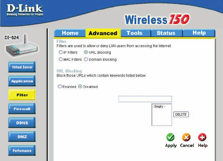
Advanced > Filters > URL Blocking
Filters-
URL Blocking is used to deny LAN computers from accessing specic web sites by the
URL. A URL is a specially formatted text string that denes a location on the Internet.
If any part of the URL contains the blocked word, the site will not be accessible and
the web page will not display. To use this feature, enter the text string to be blocked
and click Apply. The text to be blocked will appear in the list. To delete the text, just
highlight it and click Delete.
Select the lter you wish to use; in this case, URL Blocking
was chosen.
Keywords- Enter the keywords in this eld. Block URLs which contain
keywords listed below.
URL Blocking- Select Enabled or Disabled.
25
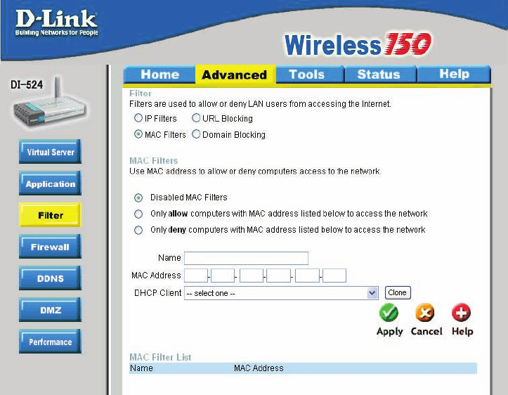
Using the Conguration Menu
Advanced > Filters > MAC Filters
Use MAC (Media Access Control) Filters to allow or deny LAN (Local Area Network)
computers by their MAC addresses from accessing the Network. You can either manually
add a MAC address or select the MAC address from the list of clients that are currently
connected to the Broadband Router.
MAC Filters- Choose Disable MAC lters; allow MAC addresses listed
below; or deny MAC addresses listed below.
Filters-
Name- Enter the name here.
MAC Address- Enter the MAC Address.
DHCP Client- Select a DHCP client from the pull-down list; click Clone to
copy that MAC Address.
Select the lter you wish to use; in this case, MAC lters was
chosen.
(continued)
26
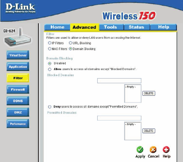
Using the Conguration Menu
Advanced > Filters > Domain Blocking
Filters-
Domain Blocking-
Blocked Domains-
Permitted
Domains-
Domain Blocking is used to allow or deny LAN (Local Area Network) computers from
accessing specic domains on the Internet. Domain blocking will deny all requests to
a specic domain such as http and ftp. It can also allow computers to access specic
sites and deny all other sites.
Select the lter you wish to use; in this case, Domain Block-
ing was chosen.
Disabled-
Allow-
Deny-
Enter the Permitted Domains in this eld
Enter the Blocked Domains in this eld
Select Disabled to disable Domain Blocking
Allows users to access all domains except Blocked Domains
Denies users access to all domains except
Permitted Domains
(continued)
27
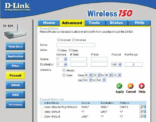
Using the Conguration Menu (continued)
Advanced > Firewall
Firewall Rules is an advanced feature used to deny or allow trafc from passing
through the DI-524. It works in the same way as IP Filters with additional settings. You
can create more detailed access rules for the DI-524. When virtual services are created
and enabled, it will also display in Firewall Rules. Firewall Rules contain all network
rewall rules pertaining to IP (Internet Protocol).
In the Firewall Rules List at the bottom of the screen, the priorities of the rules are from
top (highest priority) to bottom (lowest priority.)
Note:
The DI-524 MAC Address ltering rules have precedence over the Firewall Rules.
Firewall Rules- Enable or disable the Firewall
Name- Enter the name
Action- Allow or Deny
Source- Enter the IP Address range
Schedule- Select Always or enter the Time Range.
Destination- Enter the IP Address range; the Protocol;
and the Port Range
28
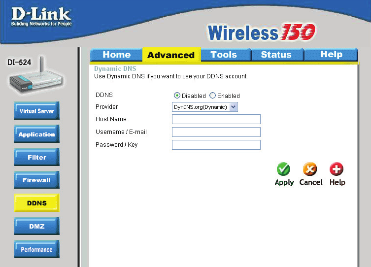
Advanced > DDNS
Using the Conguration Menu (continued)
Users who have a Dynamic DDNS account may use this feature on the DI-524.
Provider- Select from the list of DDNS servers available.
Host Name- Enter your DDNS account host name.
Username/Email- Enter your DDNS account username.
Password/Key- Enter your DDNS account password.
29
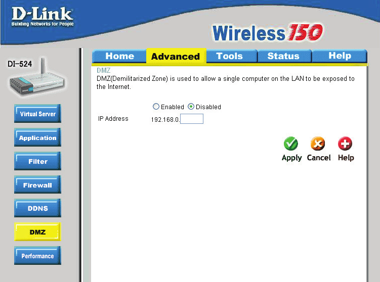
Advanced > DMZ
Using the Conguration Menu (continued)
If you have a client PC that cannot run Internet applications properly from behind the DI-
524, then you can set the client up for unrestricted Internet access. It allows a computer
to be exposed to the Internet. This feature is useful for gaming purposes. Enter the IP
address of the internal computer that will be the DMZ host. Adding a client to the DMZ
(Demilitarized Zone) may expose your local network to a variety of security risks, so
only use this option as a last resort.
DMZ- Enable or Disable the DMZ. The DMZ (Demilitarized Zone)
allows a single computer to be exposed to the internet. By
default the DMZ is disabled.
IP Address- Enter the IP Address of the computer to be in the DMZ
30
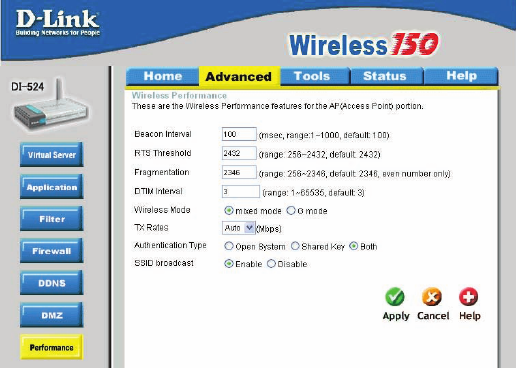
Using the Conguration Menu (continued)
Advanced > Performance
Wireless Mode- Select Short or Long Preamble. The Preamble denes the
length of the CRC block (Cyclic Redundancy Check is a com-
mon technique for detecting data transmission errors) for
communication between the wireless router and the roaming
wireless network adapters. Note: High network trafc areas
should use the shorter preamble type.
Beacon Interval- Beacons are packets sent by an Access Point to synchronize
a wireless network. Specify a value. 100 is the default setting
and is recommended.
RTS Threshold- This value should remain at its default setting of 2432. If incon-
sistent data ow is a problem, only a minor modication should
be made.
Fragmentation- The fragmentation threshold, which is specied in bytes, deter-
mines whether packets will be fragmented. Packets exceeding
the 2346 byte setting will be fragmented before transmis-
sion.2346 is the default setting
DTIM Interval- (Delivery Trafc Indication Message) 3 is the default setting. A
DTIM is a countdown informing clients of the next window for
listening to broadcast and multicast messages.
SSID Broadcast- Choose Enabled to broadcast the SSID across the network.
All devices on a network must share the same SSID (Service
Set Identier) to establish communication. Choose Disabled
if you do not wish to broadcast the SSID over the network.
TX Rates- Auto is the default selection. Selct from the drop down menu.
31
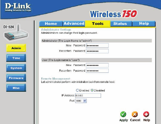
Using the Conguration Menu (continued)
Tools> Admin
At this page, the DI-524 administrator can change the system password. There are two
accounts that can access the Broadband Router’s Web-Management interface. They
are admin and user. Admin has read/write access while user has read-only access.
User can only view the settings but cannot make any changes.
Remote Management- Remote management allows the DI-524 to be congured
from the Internet by a web browser. A username and password is still required to ac-
cess the Web-Management interface. In general, only a member of your network can
browse the built-in web pages to perform Administrator tasks. This feature enables
you to perform Administrator tasks from the remote (Internet) host.
IP Address- The Internet IP address of the computer that has access to the Broad-
band Router. If you input an asterisk (*) into this eld, then any computer will be able
to access the Router. Putting an asterisk (*) into this eld would present a security risk
and is not recommended.
Port- The port number used to access the Broadband Router.
Example- http://x.x.x.x:8080 where x.x.x.x is the WAN IP address of the Broadband
Router and 8080 is the port used for the Web-Mangement interface.
Administrator-
Password-
admin is the Administrator login name
Enter the password and enter again to conrm
User-
Password-
user is the User login name
Enter the password and enter again to conrm
32
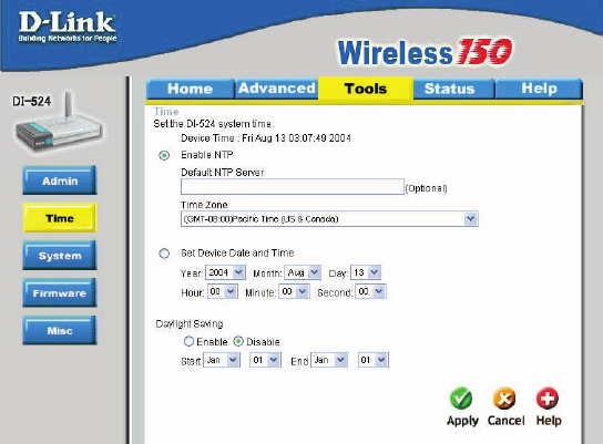
Using the Conguration Menu (continued)
Tools > Time
Time Zone- Set Device Date and Time: To manually input the time. Enter
the values in these elds for the Year, Month, Day, Hour,
Minute, and Second.
Daylight
Saving-
To select Daylight Saving time manually, select enabled or
disabled, and enter a start date and an end date for daylight
saving time.
Set the Time- To manually input the time, enter the values in these elds for the
Year, Month, Day, Hour, Minute, and Second. Click Set Time.
Default
NTP Server-
NTP is short for Network Time Protocol. NTP synchronizes
computer clock times in a network of computers.
This eld is optional.
33
Using the Conguration Menu (continued)
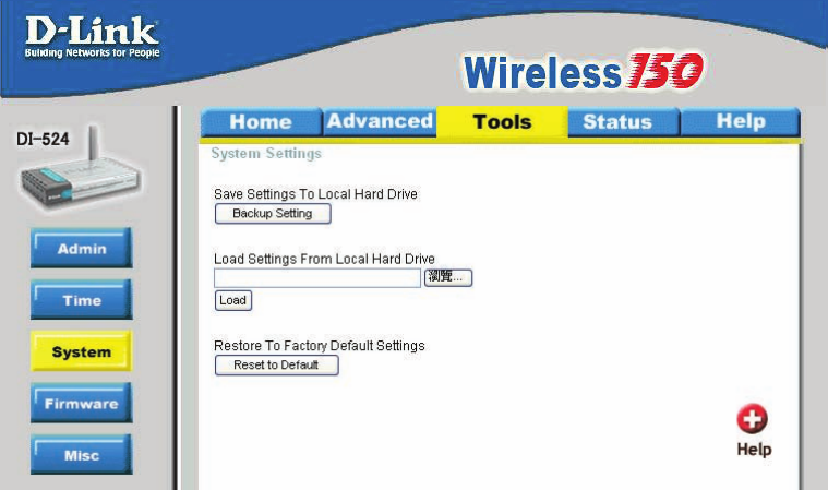
Tools > System
The current system settings can be saved as a le onto the local hard drive. The saved
le or any other saved setting le can be loaded back on the Broadband Router. To
reload a system settings le, click on Browse to browse the local hard drive and locate
the system le to be used. You may also reset the Broadband Router back to factory
settings by clicking on Restore.
Click Save to save the current settings to the local Hard Drive
Click Browse to nd the settings, then click Load
Save Settings to
Local Hard Drive-
Load Settings from
Local Hard Drive-
Restore to Factory
Default Settings- Click Restore to restore the factory default settings
34
Using the Conguration Menu (continued)
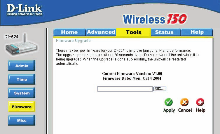
Tools > Firmware
You can upgrade the rmware of the Router here. Make sure the rmware you want
to use is on the local hard drive of the computer. Click on Browse to browse the local
hard drive and locate the rmware to be used for the update. Please check the D-Link
support site for rmware updates at http://support.dlink.com. You can download rmware
upgrades to your hard drive from the D-Link support site.
Firmware Upgrade-
Browse-
Click on the link in this screen to nd out if there is an up-
dated rmware; if so, download the new rmware to your hard
drive.
After you have downloaded the new rmware, click Browse in
this window to locate the rmware update on your hard drive.
Click Apply to complete the rmware upgrade.
35
Using the Conguration Menu (continued)
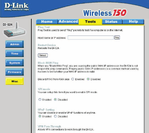
Tools > Misc
Ping Test-
Restart
Device-
Block
WAN
Ping-
Discard Ping from WAN side-
VPN
Pass
Through-
PPTP- select Enabled or Disabled
IPSec- select Enabled or Disabled
The Ping Test is used to send Ping packets to test if a computer is on the
Internet. Enter the IP Address that you wish to Ping, and click Ping
If you choose to block WAN Ping, the WAN IP Address of the DI-524
will not respond to pings. Blocking the Ping may provide some extra
security from hackers.
The DI-524 supports VPN (Virtual Private Network) pass-through for
both PPTP (Point-to-Point Tunneling Protocol) and IPSec (IP Security).
Once VPN pass-through is enabled, there is no need to open up virtual
services. Multiple VPN connections can be made through the DI-524.
This is useful when you have many VPN clients on the LAN network.
Click Reboot to restart the DI-524
Click Enabled to block the WAN ping
UPNP- To use the Universal Plug and Play feature click on Enabled. UPNP pro-
vides compatibility with networking equipment, software and peripherals
of the over 400 vendors that cooperate in the Plug and Play forum.
36
Using the Conguration Menu (continued)
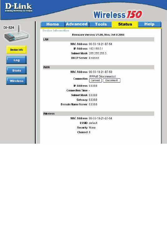
Status > Device Info
This page displays the current information for the DI-524. It will display the LAN, WAN
and MAC address information.
If your WAN connection is set up for a Dynamic IP address then a Release button
and a Renew button will be displayed. Use Release to disconnect from your ISP and
use Renew to connect to your ISP.
If your WAN connection is set up for PPPoE, a Connect button and a Disconnect but-
ton will be displayed. Use Disconnect to drop the PPPoE connection and use Connect
to establish the PPPoE connection.
This window will show the DI-524’s working status:
IP Address: WAN/Public IP Address
Subnet Mask: WAN/Public Subnet Mask
Gateway: WAN/Public Gateway IP Address
Domain Name Server: WAN/Public DNS IP Address
WAN Status: WAN Connection Status
Wireless
IP Address: LAN/Private IP Address of the DI-524
Subnet Mask: LAN/Private Subnet Mask of the DI-524
WAN
LAN
MAC Address: Displays the MAC address
SSID: Displays the current SSID
Channel: Displays the current channel
WEP: indicates whether WEP is enabled or disabled
37
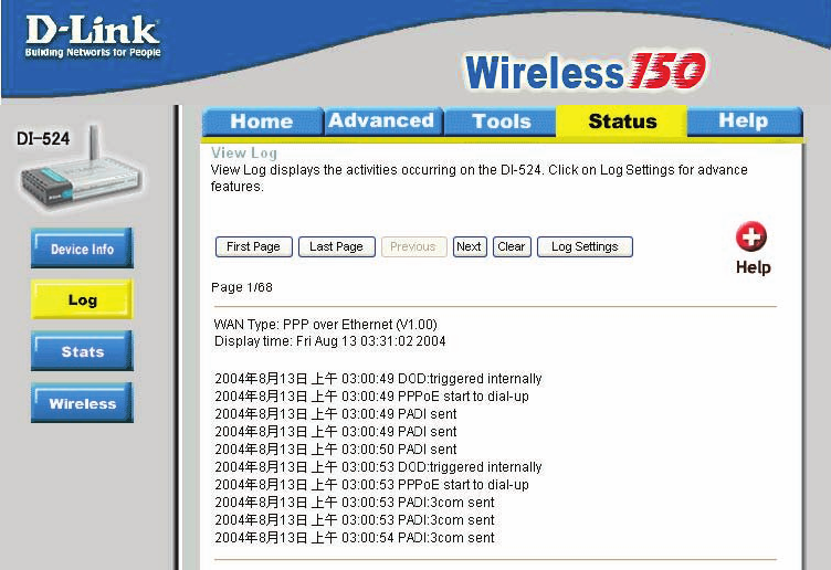
The Broadband Router keeps a running log of events and activities occurring on the
Router. If the device is rebooted, the logs are automatically cleared. You may save the
log les under Log Settings.
Using the Conguration Menu (continued)
Status > Log
View Log- First Page - The rst page of the log
Last Page - The last page of the log
Previous - Moves back one log page
Next - Moves forward one log page
Clear - Clears the logs completely
Log Settings - Brings up the page to congure the log
38
Using the Conguration Menu (continued)
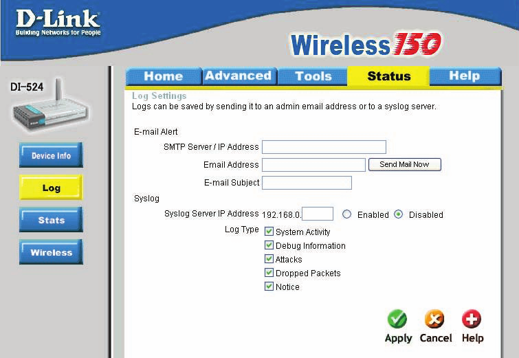
Status > Log > Log Settings
Not only does the Broadband Router display the logs of activities and events, it can
setup to send these logs to another location.
The address of the SMTP server that will be used to send the
logs
The email address to which the logs will be sent.
Click on Send Mail Now to send the email.
SMTP Server/
IP Address -
Email Address -
39
Status > Wireless
Using the Conguration Menu (continued)
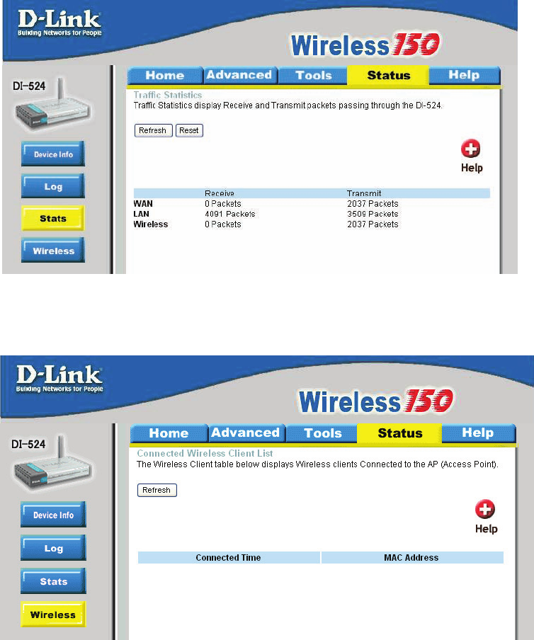
Status > Stats
The screen above displays theTrafc Statistics. Here you can view the amount of
packets that pass through the DI-524 on both the WAN and the LAN ports. The trafc
counter will reset if the device is rebooted.
The wireless client table displays a list of current connected wireless clients. This
table also displays the connection time and MAC address of the connected wireless
client.
Click on Help at any time, for more information.
40
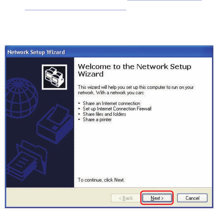
Using the Network Setup Wizard in Windows XP
In this section you will learn how to establish a network at home or work, using
Microsoft Windows XP.
Note: Please refer to websites such as http://www.homenethelp.com
and http://www.microsoft.com/windows2000 for information about networking
computers using Windows 2000, ME or 98.
Go to Start>Control Panel>Network Connections
Select Set up a home or small ofce network
Networking Basics
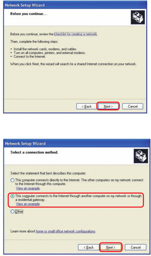
When this screen appears, Click Next.
41
Please follow all the instructions in this window:
Networking Basics
Click Next
In the following window, select the best description of your computer. If your computer
connects to the internet through a gateway/router, select the second option as shown.
Click Next
42
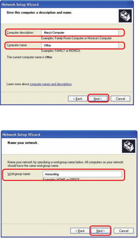
Enter a Computer description and a Computer name (optional.)
Networking Basics
Click Next
Enter a Workgroup name. All computers on your network should have the same
Workgroup name.
Click Next
43
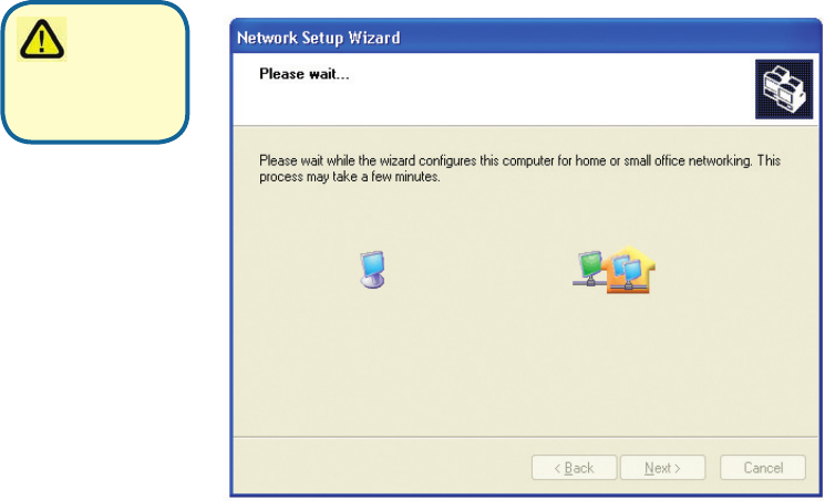
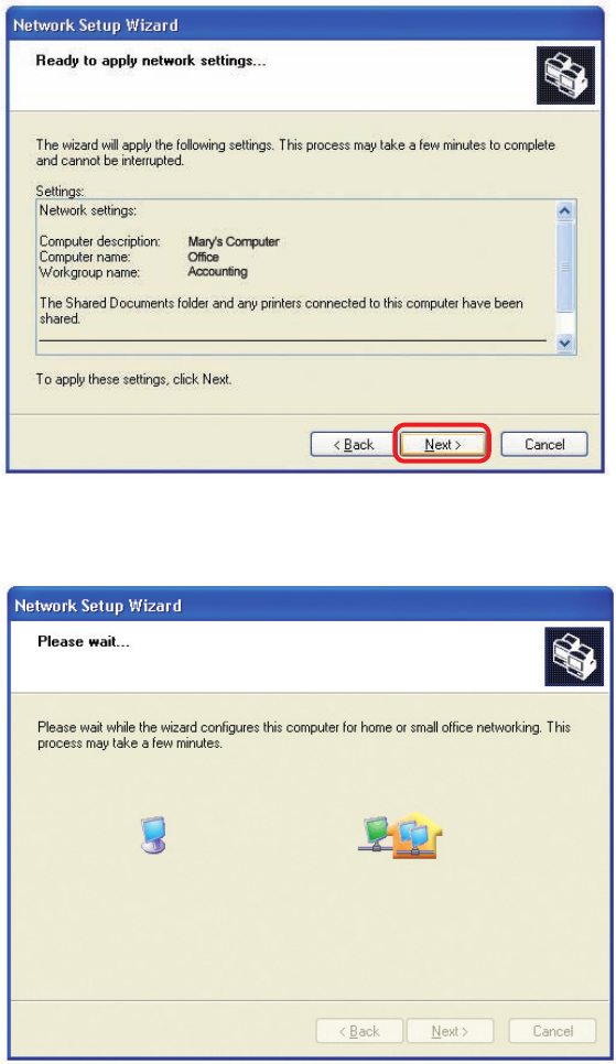
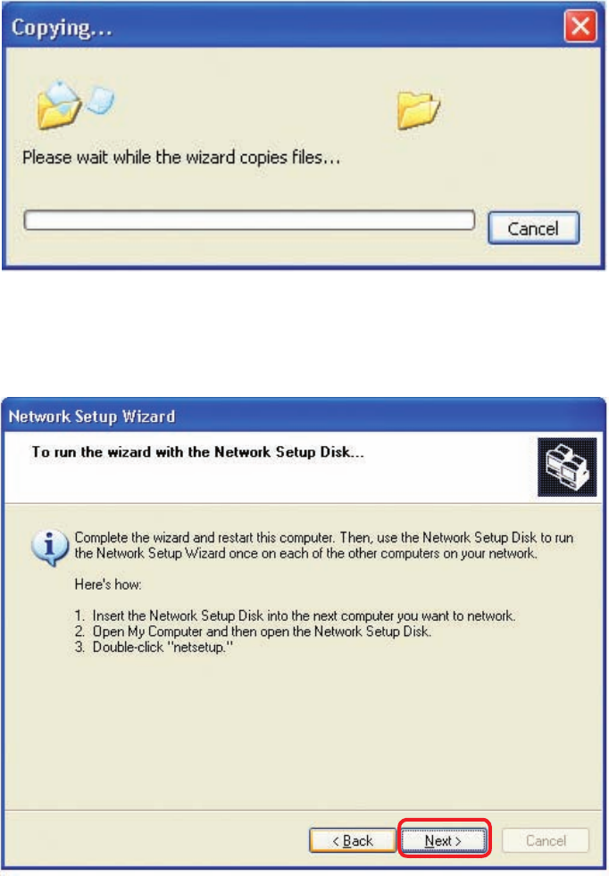
Please wait while the Network Setup Wizard applies the changes.
Networking Basics
When the changes are complete, click Next.
Please wait while the Network Setup Wizard congures the computer.
This may take a few minutes.
44
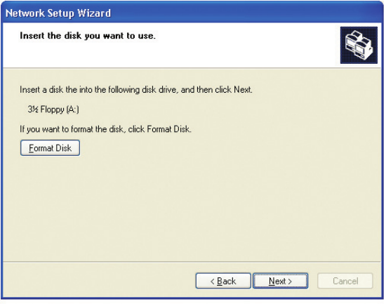
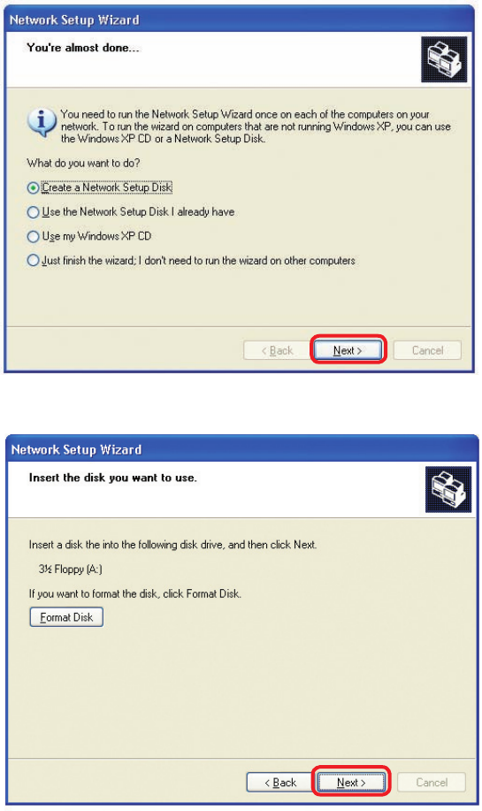
Networking Basics
In the window below, select the option that ts your needs. In this example, Create
a Network Setup Disk has been selected. You will run this disk on each of the
computers on your network. Click Next.
Insert a disk into the Floppy Disk Drive, in this case drive A.
Click Next.
45
Networking Basics
Please read the information under Here’s how in the screen below. After you complete
the Network Setup Wizard you will use the Network Setup Disk to run the Network
Setup Wizard once on each of the computers on your network. To continue click Next.
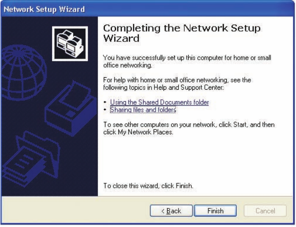
46
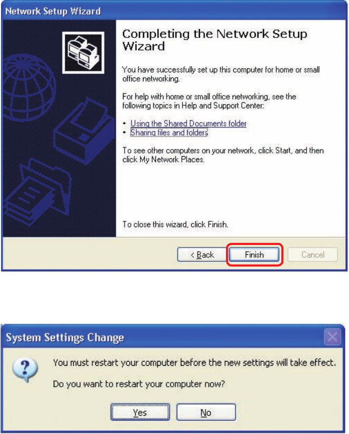
Networking Basics
Please read the information on this screen, then click Finish to complete the
Network Setup Wizard.
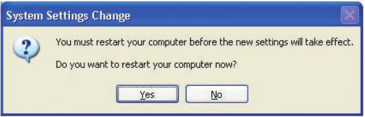
The new settings will take effect when you restart the computer. Click Yes to restart
the computer.
You have completed conguring this computer. Next, you will need to run the Network
Setup Disk on all the other computers on your network. After running the Network
Setup Disk on all your computers, your new wireless network will be ready to use.
47
Networking Basics
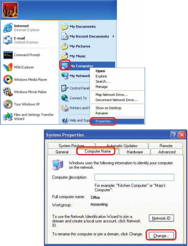
Naming your Computer
To name your computer, please follow these directions:In Windows XP:
Click Start (in the lower left corner of the screen)
Right-click on My Computer
Select Properties and click
Select the Computer
Name Tab in the System
Properties window.
You may enter a
Computer Description
if you wish; this eld is
optional.
To rename the computer
and join a domain, Click
Change.

48
Networking Basics
Naming your Computer
In this window, enter the
Computer name
Select Workgroup and enter
the name of the Workgroup
All computers on your
network must have the same
Workgroup name.
Click OK
Checking the IP Address in Windows XP
The wireless adapter-equipped computers in your network must be in the same IP Ad-
dress range (see Getting Started in this manual for a denition of IP Address Range.)
To check on the IP Address of the adapter, please do the following:
Right-click on
the Local Area
Connection icon
in the task bar
Click on Status
49
Networking Basics
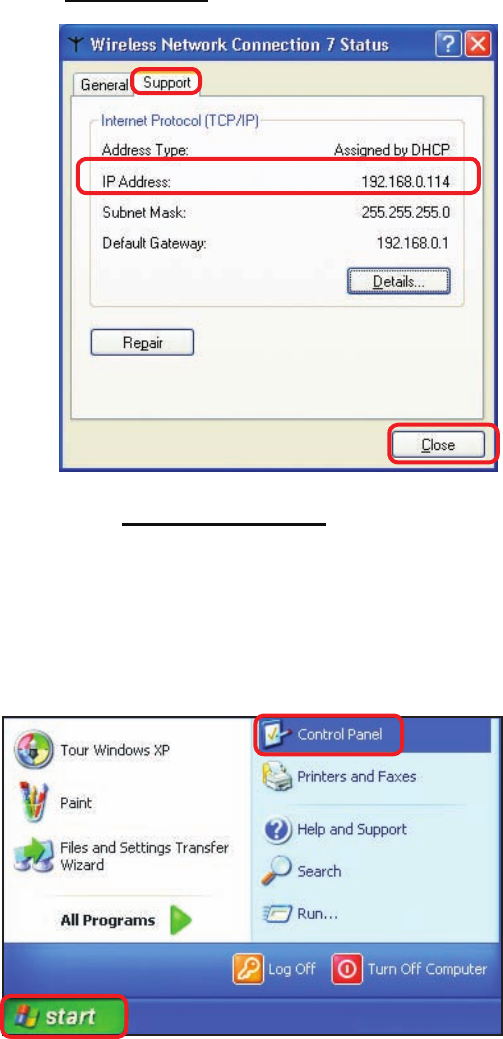
Checking the IP Address in Windows XP
This window will appear.
Click the
Support tab
Click Close
Assigning a Static IP Address in Windows XP/2000
Note: Residential Gateways/Broadband Routers will automatically assign IP Addresses
to the computers on the network, using DHCP (Dynamic Host Conguration Protocol)
technology. If you are using a DHCP-capable Gateway/Router you will not need to
assign Static IP Addresses.
If you are not using a DHCP capable Gateway/Router, or you need to assign a Static
IP Address, please follow these instructions:
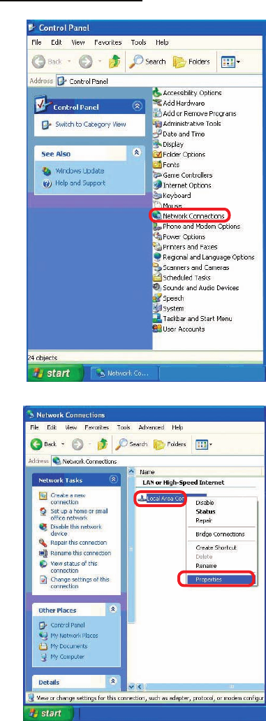
Go to Start
Double-click on
Control Panel
50
Networking Basics
Assigning a Static IP Address in Windows XP/2000
Double-click
on Network
Connections
Double-click on
Properties
Right-click on Local Area
Connections
51
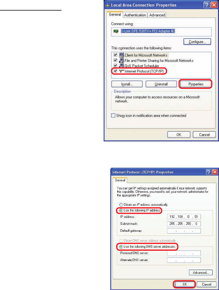
Input your IP address and
subnet mask. (The IP
Addresses on your network
must be within the same
range. For example, if
one computer has an IP
Address of 192.168.0.2,
the other computers should
have IP Addresses that are
sequential, like 192.168.0.3
and 192.168.0.4. The subnet
mask must be the same for
all the computers on the
network.)
Networking Basics
Assigning a Static IP Address
in Windows XP/2000
Input your DNS server
addresses. (Note: If you
are entering a DNS server,
you must enter the IP
Address of the Default
Gateway.)
The DNS server information will be supplied
by your ISP (Internet Service Provider.)
Click OK
Click on Internet Protocol
(TCP/IP)
Click Properties
52
Networking Basics
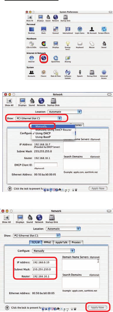
Assigning a Static IP Address with Macintosh OSX
Go to the Apple Menu and select
System Preferences
cClick on Network
Select Built-in Ethernet in the
Show pull-down menu
Select Manually in the
Congure pull-down menu
Input the Static IP Address,
the Subnet Mask and the
Router IP Address in the
appropriate elds
Click Apply Now
53
Networking Basics
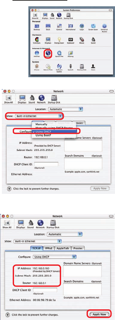
Selecting a Dynamic IP Address with Macintosh OSX
Go to the Apple Menu and select
System Preferences
Click on Network
Select Built-in Ethernet in the
Show pull-down menu
Select Using DHCP in the
Congure pull-down menu
Click Apply Now
The IP Address, Subnet
mask, and the Router’s IP
Address will appear in a few
seconds
54
Networking Basics
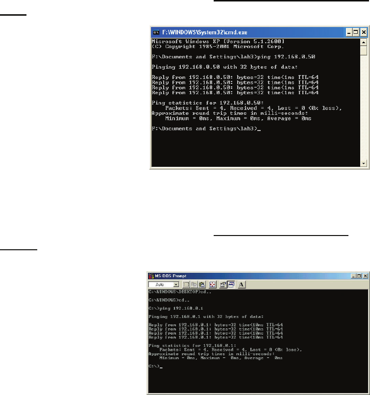
Checking the Wireless Connection by Pinging in Windows XP and
2000
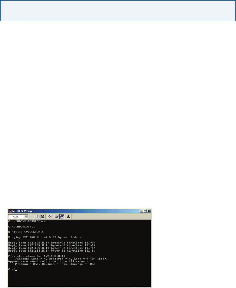
Checking the Wireless Connection by Pinging in Windows Me
and 98
Go to Start > Run >
type cmd. A window
similar to this one
will appear. Type
ping xxx.xxx.xxx.
xxx, where xxx is
the IP Address of
the Wireless Router
or Access Point.
A good wireless
connection will show
four replies from
the Wireless Router
or Acess Point, as
shown.
Go to Start > Run
> type command.
A window similar
to this will appear.
Type ping xxx.xxx.
xxx.xxx where xxx
is the IP Address
of the Wireless
Router or Access
Point. A good
wireless connection
will show four
replies from the
wireless router or
access point, as
shown.
55
Troubleshooting
This Chapter provides solutions to problems that can occur during the installation and
operation of the DI-524 Wireless Broadband Router. We cover various aspects of the
network setup, including the network adapters. Please read the following if you are
having problems.
Note: If you have
changed the default IP
Address, make sure to
ping the correct IP Ad-
dress assigned to the
DI-524.
Note: It is recommended that you use an Ethernet connection to
congure the DI-524 Wireless Broadband Router.
1. The computer used to congure the DI-524 cannot access the
Conguration menu.
Check that the Ethernet LED on the DI-524 is ON. If the LED is not
ON, check that the cable for the Ethernet connection is securely
inserted.
Check that the Ethernet Adapter is working properly. Please see
item 3 (Check that the drivers for the network adapters are
installed properly) in this Troubleshooting section to check that
the drivers are loaded properly.
Check that the IP Address is in the same range and subnet as the
DI-524. Please see Checking the IP Address in Windows XP in
the Networking Basics section of this manual.
Note: The IP Address of the DI-524 is 192.168.0.1. All the computers on the
network must have a unique IP Address in the same range, e.g., 192.168.0.x.
Any computers that have identical IP Addresses will not be visible on the
network. They must all have the same subnet mask, e.g., 255.255.255.0
Do a Ping test to make sure that the DI-524 is responding. Go to
Start>Run>Type Command>Type ping 192.168.0.1. A successful
ping will show four replies.
56
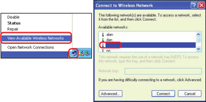
2. The wireless client cannot access the Internet in the
Infrastructure mode.
Make sure the wireless client is associated and joined with the correct Access
Point. To check this connection: Right-click on the Local Area Connection
icon in the taskbar> select View Available Wireless Networks. The Connect to
Wireless Network screen will appear. Please make sure you have selected the
correct available network, as shown in the illustrations below.
Troubleshooting
Check that the IP Address assigned to the wireless adapter is within
the same IP Address range as the access point and gateway. (Since
the DI-524 has an IP Address of 192.168.0.1, wireless adapters must
have an IP Address in the same range, e.g., 192.168.0.x. Each device
must have a unique IP Address; no two devices may have the same IP
Address. The subnet mask must be the same for all the computers on
the network.) To check the IP Address assigned to the wireless adapter,
double-click on the Local Area Connection icon in the taskbar >
select the Support tab and the IP Address will be displayed. (Please
refer to Checking the IP Address in the Networking Basics section of
this manual.)
If it is necessary to assign a Static IP Address to the wireless adapter,
please refer to the appropriate section in Networking Basics. If you
are entering a DNS Server address you must also enter the Default
Gateway Address. (Remember that if you have a DHCP-capable router,
you will not need to assign a Static IP Address. See Networking
Basics: Assigning a Static IP Address.)
57
Troubleshooting
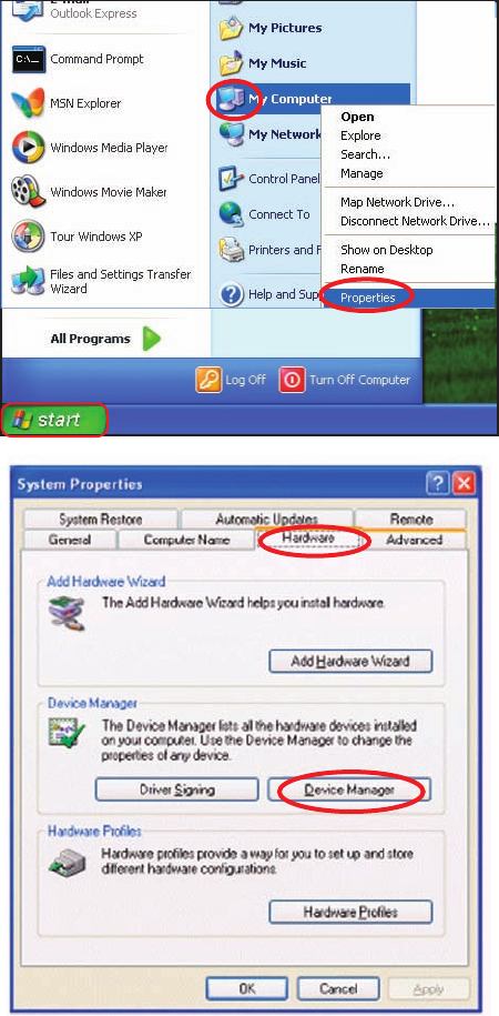
3. Check that the drivers for the network adapters are
installed properly.
You may be using different network adapters than those illustrated here, but this
procedure will remain the same, regardless of the type of network adapters you are
using.
Click Device
Manager
Select the
Hardware
Tab
Go to Start >
My Computer >
Properties
58
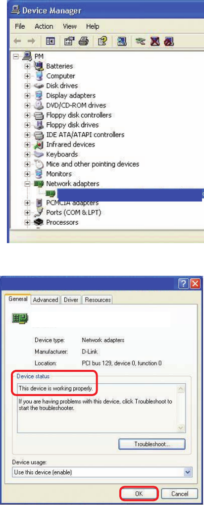
Troubleshooting
Double-click
on Network
Adapters
Right-click on D-Link
AirPlus DWL-G650
Wireless Cardbus
Adapter (In this example
we use the DWL-G650;
you may be using other
network adapters, but
the procedure will remain
the same.)
Select Properties
to check that
the drivers are
installed properly
Look under Device
Status to check that the
device is working
properly
Click OK
D-Link AirPlus DWL-G650 Wireless Cardbus Adapter
D-Link AirPlus DWL-G650 Wireless Cardbus Adapter
D-Link AirPlus DWL-G650
59
Troubleshooting
4. What variables may cause my wireless products
to lose reception?
D-Link products let you access your network from virtually anywhere you want. However,
the positioning of the products within your environment will affect the wireless range.
Please refer to Installation Considerations in the Wireless Basics section of this
manual for further information about the most advantageous placement of your D-Link
wireless products.
5. Why does my wireless connection keep dropping?
6. Why can’t I get a wireless connection?
If you have enabled Encryption on the DI-524, you must also enable encryption on all
wireless clients in order to establish a wireless connection.
Make sure that the SSID on the Router and the Wireless Client are exactly the
same. If they are not, wireless connection will not be established.
For 802.11b, the Encryption settings are: 64, 128, or 256 bit. Make sure that
the encryption bit level is the same on the Router and the Wireless Client.
Move the DI-524 and the wireless client into the same room and then test the
wireless connection.
Disable all security settings. (WEP, MAC Address Control)
Antenna Orientation- Try different antenna orientations for the DI-524. Try to
keep the antenna at least 6 inches away from the wall or other objects.
If you are using 2.4GHz cordless phones, X-10 equipment or other home
security systems, ceiling fans, and lights, your wireless connection will degrade
dramatically or drop altogether. Try changing the Channel on your Router, Access
Point and Wireless adapter to a different Channel to avoid interference.
Keep your product away (at least 3-6 feet) from electrical devices that generate
RF noise, like microwaves, Monitors, electric motors, etc.
60
Troubleshooting
6. Why can’t I get a wireless connection? (continued)
Turn off your DI-524 and the client. Turn the DI-524 back on again, and then
turn on the client.
Check that the LED indicators are indicating normal activity. If not, check that
the AC power and Ethernet cables are rmly connected.
Make sure that all devices are set to Infrastructure mode.
Check that the IP Address, subnet mask, gateway and DNS settings are cor-
rectly entered for the network.
If you are using 2.4GHz cordless phones, X-10 equipment or other home se-
curity systems, ceiling fans, and lights, your wireless connection will degrade
dramatically or drop altogether. Try changing the Channel on your DI-524, and
on all the devices in your network to avoid interference.
Keep your product away (at least 3-6 feet) from electrical devices that generate
RF noise, like microwaves, Monitors, electric motors, etc.
7. I forgot my encryption key.
Reset the DI-524 to its factory default settings and restore the other devices on
your network to their default settings. You may do this by pressing the Reset
button on the back of the unit. You will lose the current conguration settings.