D Link IR513A2 Wireless N Pocket Router User Manual DIR 513 20130115
D Link Corporation Wireless N Pocket Router DIR 513 20130115
UserManual.wiki
>
D Link
>
IR513A2 User Manual
User Manual
Navigation menu
Upload a User Manual
Namespaces
Wiki Guide
HTML
PDF
Info
Views
User Manual
Discussion / Help
Navigation
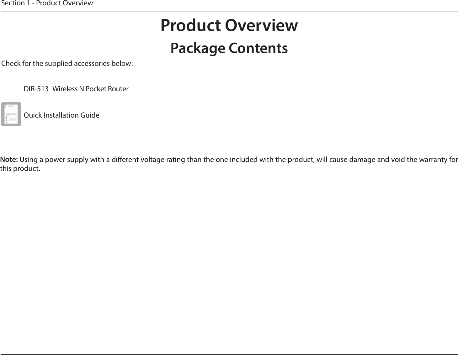
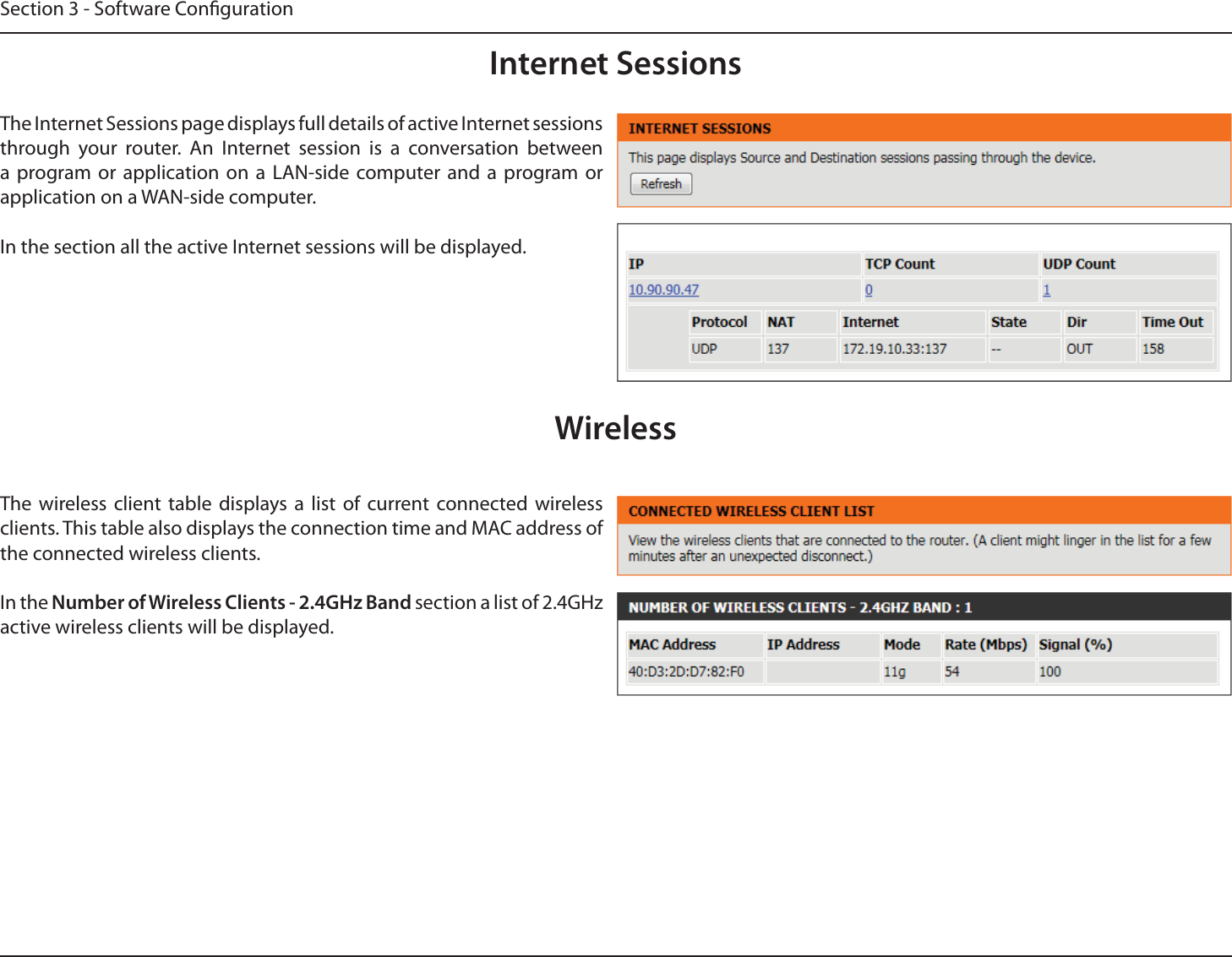
![Section 1 - Product OverviewSystem RequirementsNetwork RequirementsXI"OC@MI@O=<N@? <=G@JM!0)HJ?@HX&"""IJMBRDM@G@NN>GD@IONX"OC@MI@OWeb-based Conguration Utility RequirementsComputer with the following:X4DI?JRN]*<>DIOJNCJM)DIPS=<N@?JK@M<ODIBNTNO@HXIDINO<GG@?"OC@MI@O<?<KO@MBrowser Requirements:X&IO@MI@O"SKGJM@MJMCDBC@MX CMJH@JMCDBC@MX#DM@AJSJMCDBC@MX0<A<MDJMCDBC@MRDOC'<Q<JMCDBC@MWindows® Users:*<F@NPM@TJPC<Q@OC@G<O@NOQ@MNDJIJA'<Q<DINO<GG@?3DNDORRRE<Q<>JHOJ?JRIGJ<?OC@G<O@NOQ@MNDJICD Installation Wizard RequirementsComputer with the following:X4DI?JRN]3DNO<]JM5-RDOC0@MQD>@-<>FXIDINO<GG@?"OC@MI@O<?<KO@M](https://usermanual.wiki/D-Link/IR513A2/User-Guide-1893334-Page-4.png)