D Link IR513A2 Wireless N Pocket Router User Manual DIR 513 20130115
D Link Corporation Wireless N Pocket Router DIR 513 20130115
D Link >
User Manual

D-Link reserves the right to revise this publication and to make changes in the content hereof without obligation to notify any person or organization
of such revisions or changes.
Preface
Trademarks
D-Link and the D-Link logo are trademarks or registered trademarks of D-Link Corporation or its subsidiaries in the United States or other countries.
All other company or product names mentioned herein are trademarks or registered trademarks of their respective companies.
Copyright © 2012 by D-Link Systems, Inc.
All rights reserved. This publication may not be reproduced, in whole or in part, without prior expressed written permission from D-Link Systems, Inc.
Section 1 - Product Overview
Product Overview
Package Contents
DIR-513 Wireless N Pocket Router
Quick Installation Guide
Check for the supplied accessories below:
Note:
this product.

Section 1 - Product Overview
System Requirements
Network Requirements
XI"OC@MI@O=<N@? <=G@JM!0)HJ?@H
X&"""IJMBRDM@G@NN>GD@ION
X"OC@MI@O
Web-based Conguration
Utility Requirements
Computer with the following:
X4DI?JRN]*<>DIOJNCJM)DIPS=<N@?JK@M<ODIBNTNO@H
XIDINO<GG@?"OC@MI@O<?<KO@M
Browser Requirements:
X&IO@MI@O"SKGJM@MJMCDBC@M
X CMJH@JMCDBC@M
X#DM@AJSJMCDBC@M
X0<A<MDJMCDBC@MRDOC'<Q<JMCDBC@M
Windows® Users:*<F@NPM@TJPC<Q@OC@G<O@NOQ@MNDJIJA'<Q<
DINO<GG@?3DNDORRRE<Q<>JHOJ?JRIGJ<?OC@G<O@NOQ@MNDJI
CD Installation Wizard
Requirements
Computer with the following:
X4DI?JRN]3DNO<]JM5-RDOC0@MQD>@-<>F
XIDINO<GG@?"OC@MI@O<?<KO@M
Section 1 - Product Overview
Features
t Internet Connectivity - In conjunction with a DSL or Cable Modem, this device provides high-speed Internet
connectivity to your local network for up to four wired devices.
t Wireless LAN functionality - This router supports features like WMM, RF Output Level Control, WPS, and much
more.
t Networking - This router comes with one WAN port and four LAN ports that enable up to four computers on your
local network to be connected.
t Wireless Distribution System (WDS) mode- The router supports WDS where it can extend the network coverage
from another router.
t Advanced Security - The router also supports a range of security features like Network Filtering, Access Control,
Website Filtering, Inbound Filtering, and SPI.
t IPv6 - This router supports local IPv6 support and IPv6 Internet Connection.
tUser-friendly Setup Wizard -
your router qickly and conveniently.
The DIR-513’s

Section 2 - Hardware Installation
Wireless Installation Considerations
The router lets you access your network using a wireless connection from virtually anywhere within the operating range of your wireless network.
Keep in mind, however, that the number, thickness and location of walls, ceilings, or other objects that the wireless signals must pass through, may
limit the range. Ranges vary depending on the types of materials and background RF (radio frequency) noise in your home or oce. The key to
maximizing the wireless range is to follow these basic guidelines:
1. Keep the number of walls and ceilings between the D-Link router and other network devices to a minimum. Each wall or
ceiling can reduce your adapter’s range from 3 to 90 feet (1 to 30 meters.) Position your devices so that the number of walls
and/or ceilings is minimized.
2. Be aware of the direct line between network devices. A wall that is 1.5 feet thick (0.5 meters), at a 45-degree angle appears to
be almost 3 feet (1 meter) thick. At a 2-degree angle it looks over 42 feet (14 meters) thick. Position devices so that the signal
will travel straight through a wall or ceiling (instead of at an angle) for better reception.
3. Try to position access points, wireless routers, and computers so that the signal passes through open doorways and drywall.
Materials such as glass, metal, brick, insulation, concrete and water can aect wireless performance. Large objects such as sh
tanks, mirrors, le cabinets, metal doors and aluminum studs may also have a negative eect on range.
4. Keep your product at least 3 to 6 feet (1-2 meters) away from electrical devices or appliances that generate RF noise.
5. If you are using 2.4 GHz cordless phones, make sure that the 2.4 GHz phone base is as far away from your wireless device as
possible. The base transmits a signal even if the phone in not in use. In some cases, cordless phones, X-10 wireless devices, and
electronic equipment such as ceiling fans, uorescent lights, and home security systems may dramatically degrade wireless
connectivity.

Section 2 - Hardware Installation
Connect to Cable/DSL/Satellite Modem
If you are connecting the router to a Cable/DSL/Satellite Modem, please follow the steps below:
1. Place the router in an open and central location. Do not plug the power adapter into the router.
2. Turn the power o on your modem. If there is no on/o switch, unplug the modem’s power adapter. Shut down your computer.
3. Unplug the Ethernet cable (that connects your computer to your modem) from your computer and place it into the Internet
port on the router.
4. Plug an Ethernet cable into one of the LAN ports on the router. Plug the other end into the Ethernet port on your computer.
5. Turn on or plug in your modem. Wait for the modem to boot (about 30 seconds).
6. Plug the power adapter into the router and connect to an outlet or power strip. Wait about 30 seconds for the router to boot
up.
7. Turn on your computer.
8. Verify that the Power LED on the router is lit. If the Power LED does not light up, make sure your computer, modem, and router
are powered, on and verify that the cables connected correctly.
9. In a later section in this manual we’ll discuss the Web GUI conguration of the router in more detail..
Section 3 - Software Conguration
Conguration
This section will show you how to congure your new D-Link wireless router using the web-based conguration utility.
Web-based Conguration Utility
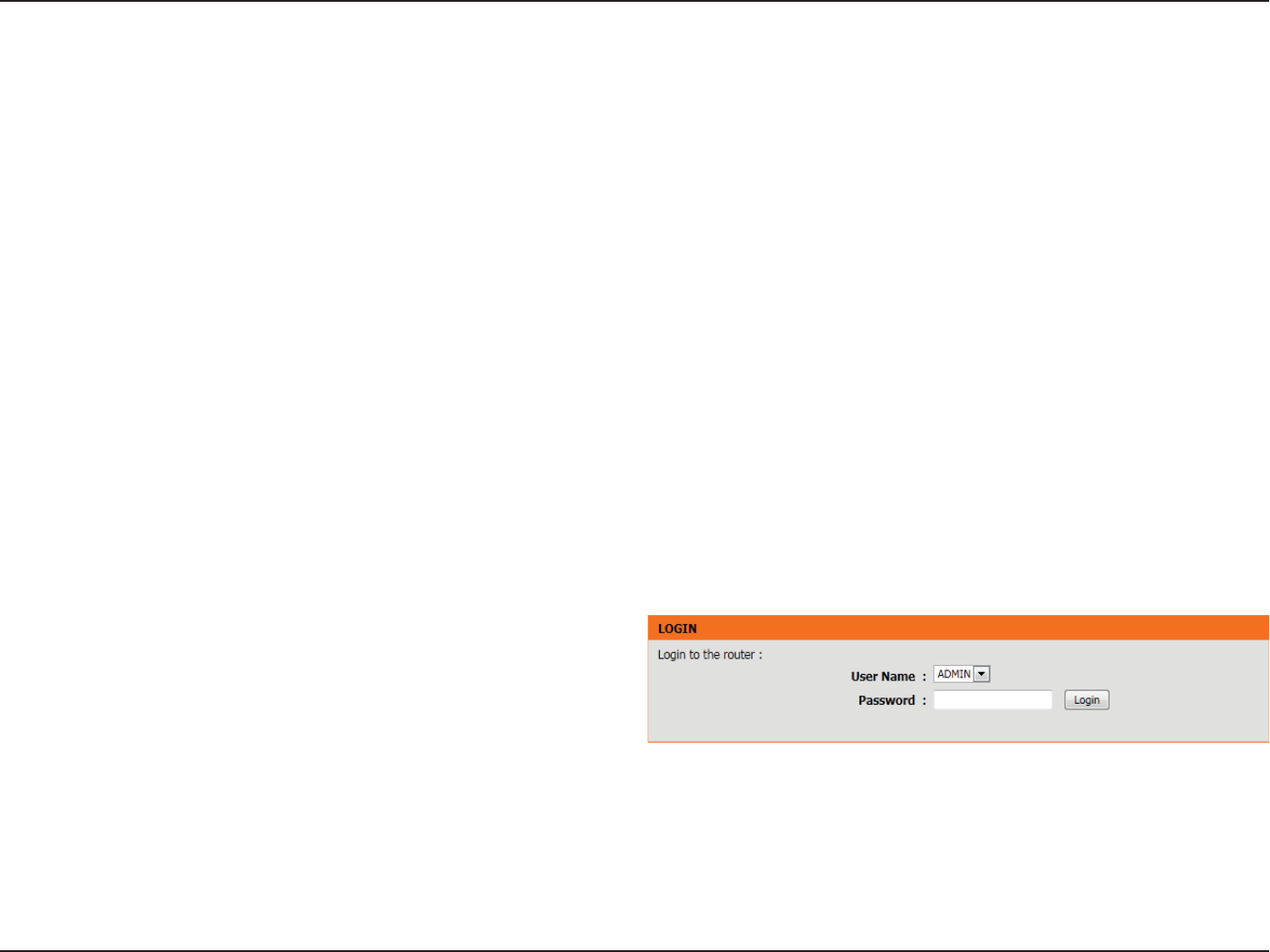
To access the conguration utility, open a web browser such as Internet
Explorer and enter the IP address of the router (192.168.0.1).
You may also connect using the NetBIOS name in the address bar
(http://dlinkrouter).
Enter your password. Admin is the default username and cannot be
changed. The password is left blank by default.
If you get a Page Cannot be Displayed error message, please refer to the
Troubleshooting section for assistance.
Click Login to log into the Router.

Section 3 - Software Conguration
Setup Wizard
Click Internet Connection Setup Wizard to quickly congure your
router. Skip to the next page.
If you want to enter your settings without running the wizard, click
Manual Conguration and skip to page 20.
Internet Connection
Section 3 - Software Conguration
Internet Connection(Setup Wizard)
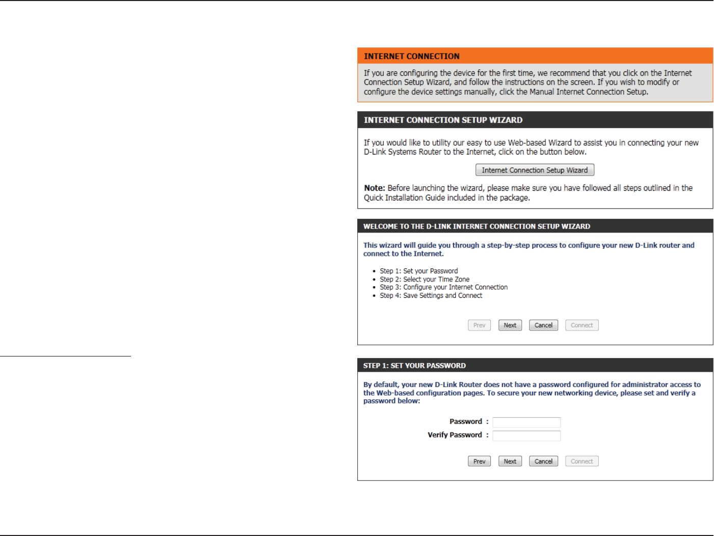
When conguring the router for the rst time, we recommend that you
click Internet Connection Setup Wizard, and follow the instructions
on the screen. This wizard is designed to assist user with a quick and
easy method to congure the Internet connection of this router.
Anytime during the Internet Connection Setup Wizard, you can click on
Cancel to discard any changes made and return to the main Internet
page. Also you can click on Prev to return to the previous window for
re-conguration.
This wizard will guide you through a step-by-step process to congure
your new D-Link router and connect to the Internet.
Click Next to continue.
Step 1: Set Your Password
By default, the D-Link Router does not have a password congured for
administrator access to the Web-based conguration pages. To secure
your new networking device, please enter and verify a password in the
spaces provided. The two passwords must match.
Click Next to continue.
Section 3 - Software Conguration
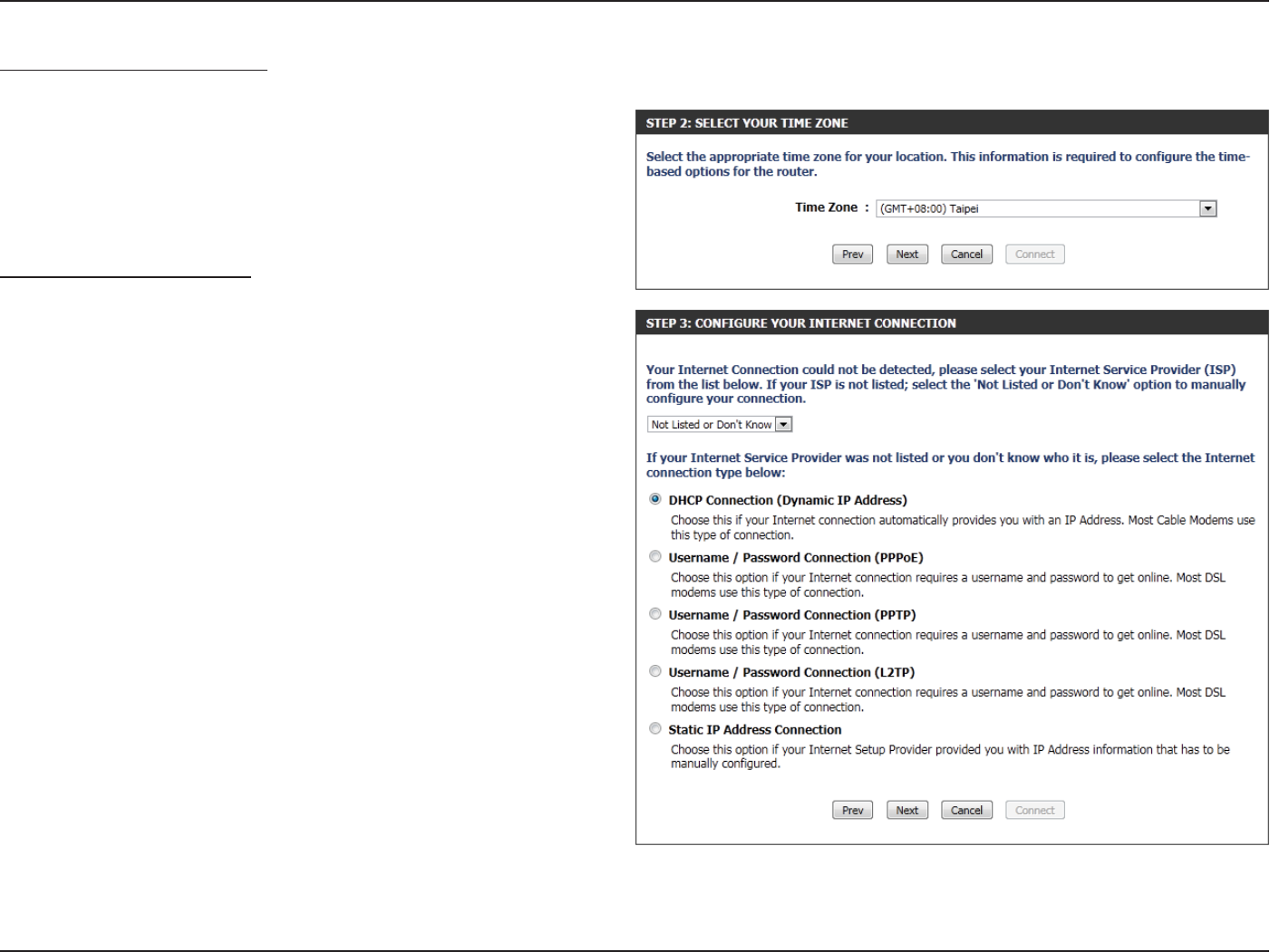
Step 2: Select Your Time Zone
Select the appropriate time zone for your location. This information is
required to congure the time-based options for the router.
Click Next to continue.
Step 3: Internet Connection
Here the user will be able to congure the Internet Connectivity used
by this device. If your ISP connection is listed in the drop-down menu
select it and click Next. If your ISP connection is not listed then you
can proceed to select any of the other manual Internet Connection
methods listed below.
Dynamic IP
Address:
Choose this if your Internet connection
automatically provides you with an IP Address.
Most Cable Modems use this type of connection.
PPPoE: Choose this option if your Internet connection
requires a PPPoE username and password to
get online. Most DSL modems use this type of
connection.
PPTP: Choose this option if your Internet connection
requires a PPTP username and password to get
online.
L2TP: Choose this option if your Internet connection
requires an L2TP username and password to get
online.
Static IP Address: Choose this option if your Internet Setup Provider
provided you with IP Address information that has
to be manually congured.
Section 3 - Software Conguration
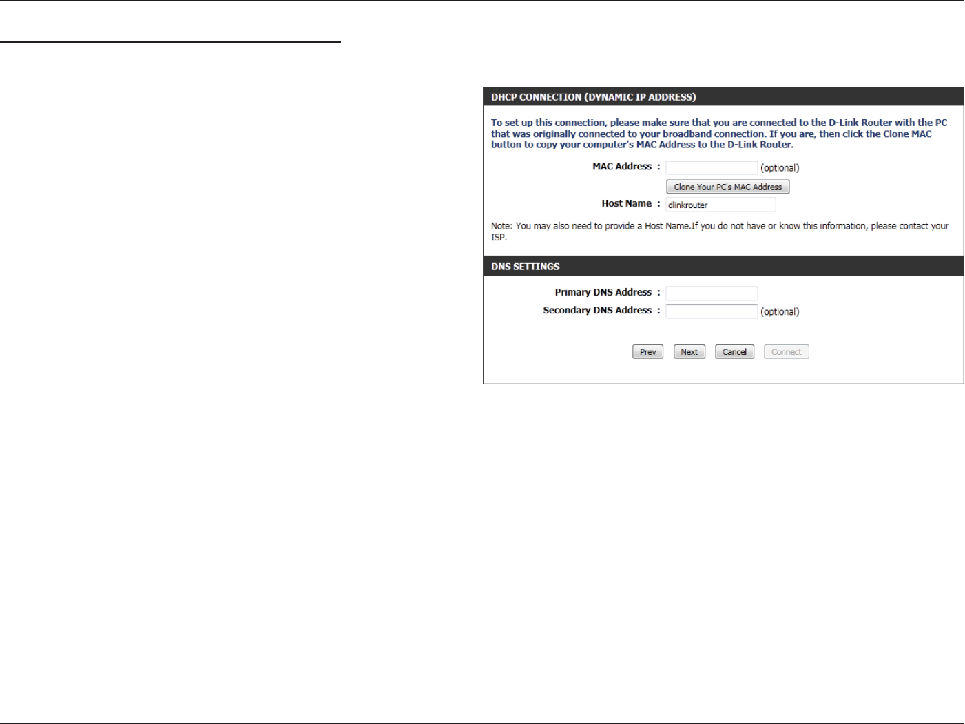
Step 3: Internet Connection (Dynamic IP Address)
After selecting the Dynamic IP Address Internet connection method,
the following page will appear.
MAC Address: Enter the MAC address of the Internet gateway
(plugged into the Internet port of this device).
Clone Button: If the conguration PC also acts as the Internet
gateway, then click on the Clone Your PC’s MAC
Address button to copy the PC’s MAC address into
the space provided. If you’re not sure, leave the
MAC Address eld blank.
Host Name: Enter the host name used. You may also need to
provide a Host Name. If you do not have or know
this information, please contact your ISP.
Primary DNS
Address:
Enter the Primary DNS IP address used.
Secondary DNS
Address:
Enter the Secondary DNS IP address used. This eld is normally optional. Only one DNS address is required for a functional
Internet connection, but using a second DNS address provides more stability.
Click Next to continue.
Section 3 - Software Conguration
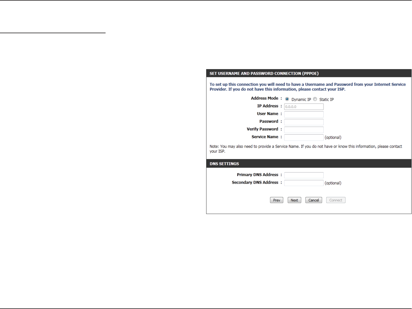
Step 3: Internet Connection (PPPoE)
After selecting the PPPoE Internet connection method, the following
page will appear:
Address Mode: The user can specify whether this Internet
connection requires the use of a Dynamic or Static
IP address. PPPoE usually requires a Dynamic IP
conguration.
IP Address: Enter the PPPoE IP address used. This option is
only available if Static IP is selected.
User Name: Enter the PPPoE account user name used. This
information is given by the ISP.
Password: Enter the PPPoE account password used. This
information is given by the ISP.
Verify Password: Re-enter the PPPoE account password used.
Service Name: This optional eld enables the user to enter a
service name to identify this Internet connection.
Primary DNS
Address:
Enter the Primary DNS IP address used.
Click Next to continue.
Section 3 - Software Conguration
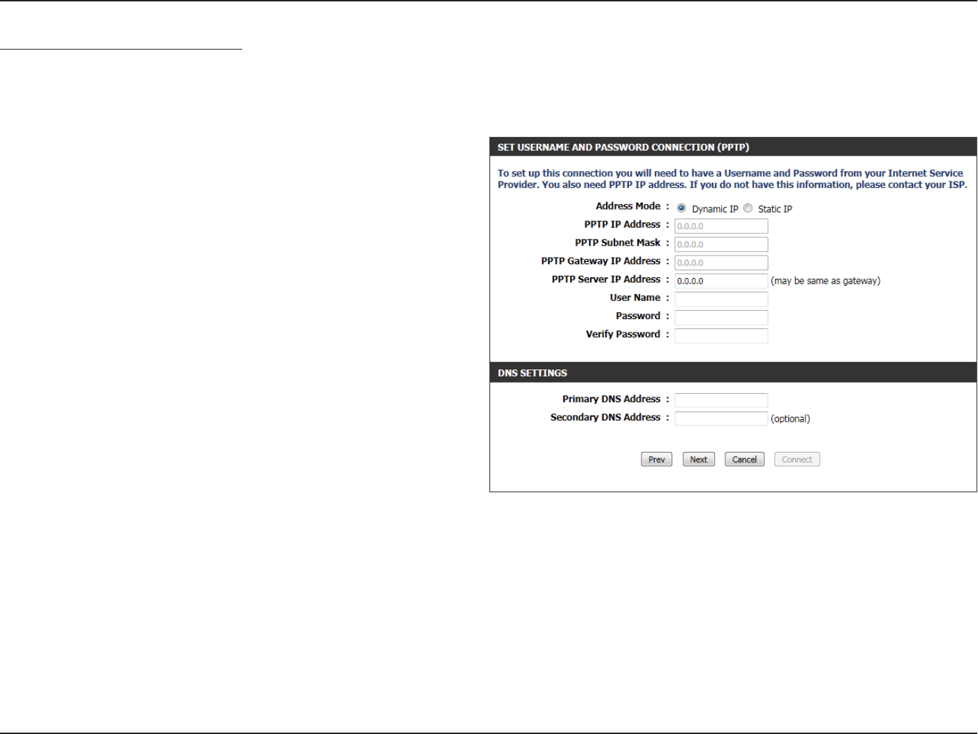
Step 3: Internet Connection (PPTP)
After selecting the PPTP Internet connection method, the following page
will appear:
Address Mode: Here the user can specify whether this Internet
connection requires the use of a Dynamic or Static
IP address. PPTP usually requires a Dynamic IP
conguration.
PPTP IP Address: Enter the PPTP IP address used here. This option is
only available if Static IP is selected.
PPTP Subnet
Mask:
Enter the PPTP Subnet Mask used.
PPTP Gateway IP
Address:
Enter the PPTP Gateway IP address used.
PPTP Server IP
Address:
Enter the PPTP Server IP address used. This is
normally the same as the PPTP Gateway IP address.
User Name: Enter the PPTP username used.
Password: Enter the PPTP password used.
Verify Password: Re-enter the PPTP password used.
Primary DNS
Address:
Enter the Primary DNS IP address used.
Secondary DNS
Address:
Enter the Secondary DNS IP address used. This eld is normally optional. Only one DNS address is required for a functional
Internet connection, but using a second DNS address provides more stability.
Click Next to continue.
Section 3 - Software Conguration
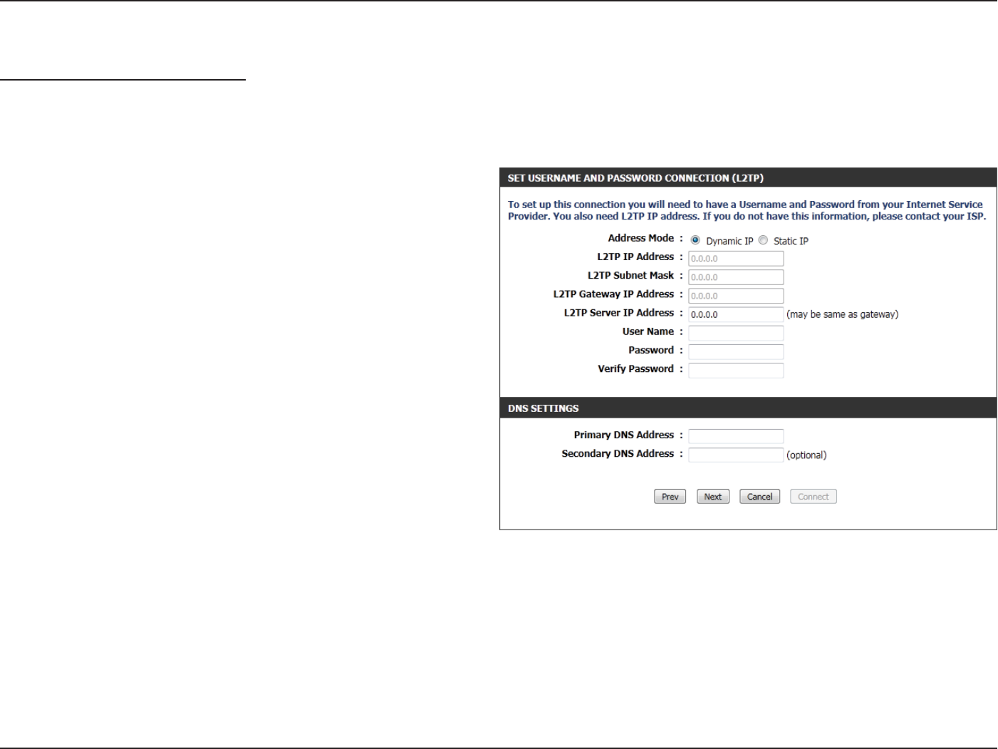
Step 3: Internet Connection (L2TP)
After selecting the L2TP Internet connection method, the following
page will appear:
Address Mode: Here the user can specify whether this Internet
connection requires the use of a Dynamic or Static
IP address. L2TP usually requires a Dynamic IP
conguration.
L2TP IP Address: Enter the L2TP IP address used here. This option is
only available if Static IP is selected.
L2TP Subnet
Mask:
Enter the L2TP Subnet Mask used.
L2TP Gateway IP
Address:
Enter the L2TP Gateway IP address used.
L2TP Server IP
Address:
Enter the L2TP Server IP address used. This is
normally the same as the L2TP Gateway IP address.
User Name: Enter the L2TP username used.
Password: Enter the L2TP password used.
Verify Password: Re-enter the L2TP password used.
Primary DNS
Address:
Enter the Primary DNS IP address used.
Secondary DNS
Address:
Enter the Secondary DNS IP address used. This eld is normally optional. Only one DNS address is required for a functional
Internet connection, but using a second DNS address provides more stability.
Click Next to continue.
Section 3 - Software Conguration
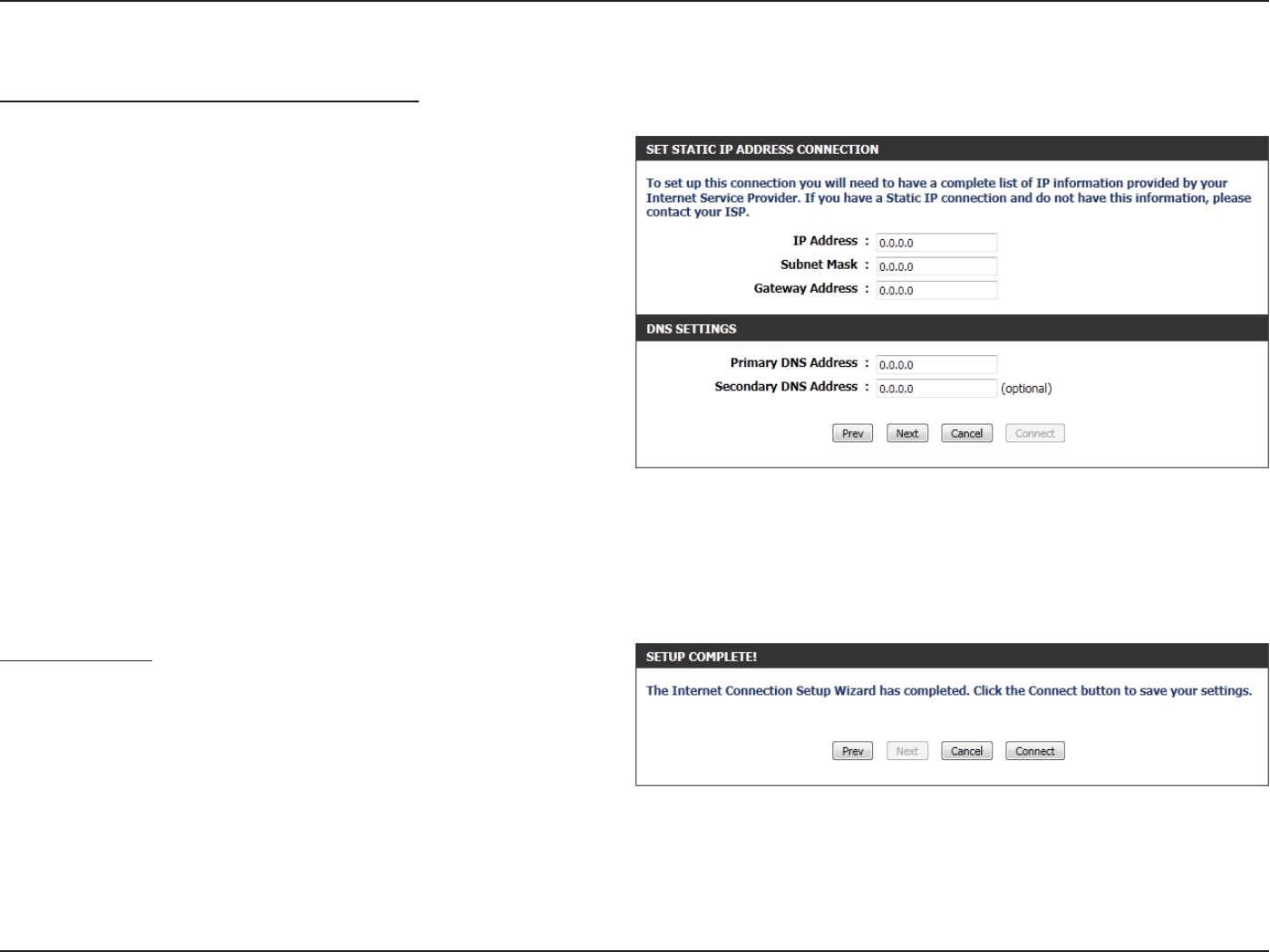
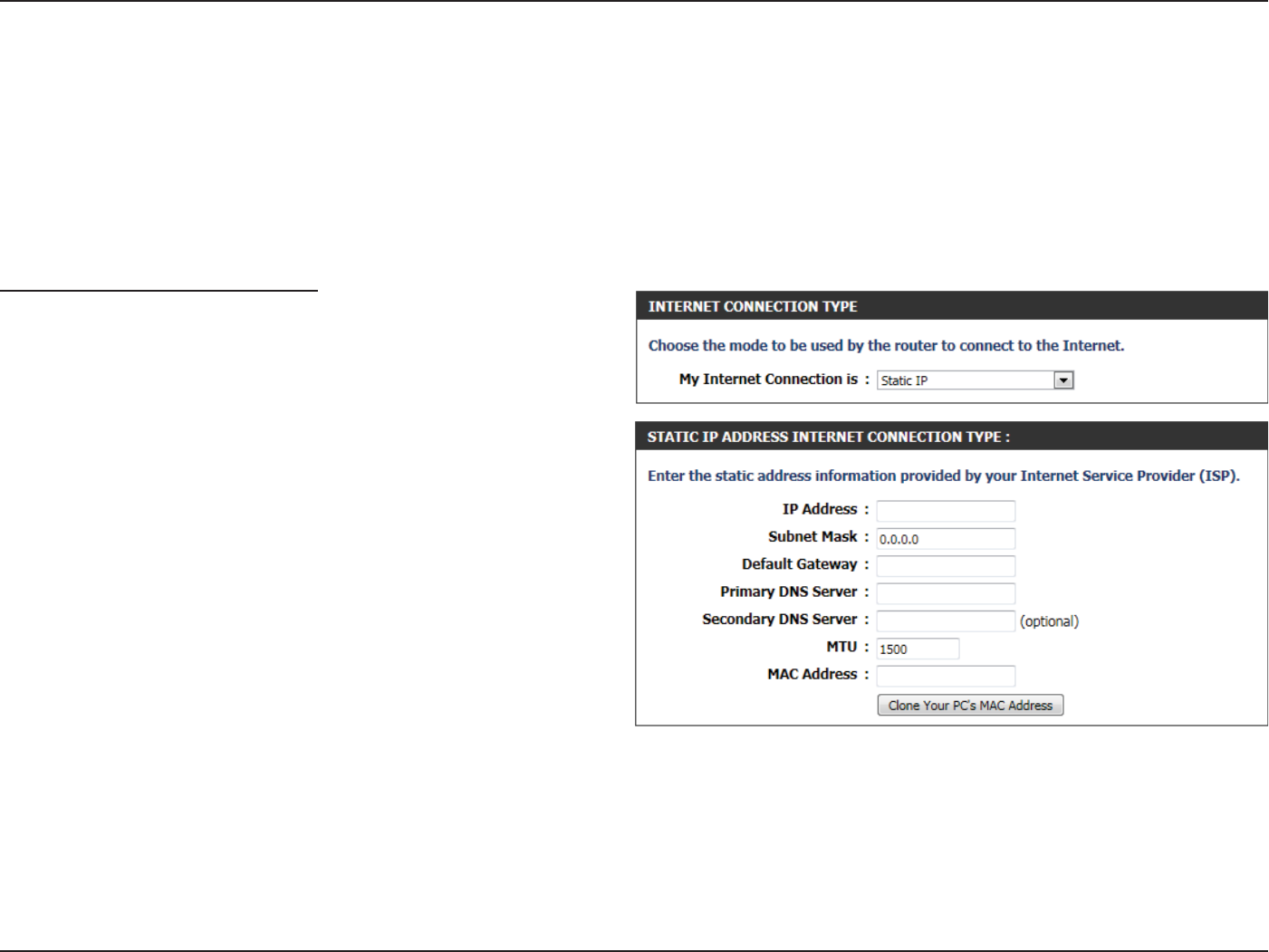
Step 3: Internet Connection (Static IP Address)
After selecting the Static IP Address Internet connection method, the
following page will appear:
IP Address: Enter the Static IP address provided by the ISP.
Subnet Mask: Enter the Subnet Mask provided by the ISP.
Gateway
Address:
Enter the Gateway IP address provided by the ISP.
Primary DNS
Address:
Enter the Primary DNS IP address used.
Secondary DNS
Address:
Enter the Secondary DNS IP address used. This
eld is normally optional. Only one DNS address
is required for a functional Internet connection,
but using a second DNS address provides more
stability.
Click Next to continue.
Setup Complete!
This is the last page of the Internet Connection Setup Wizard.
Click the Connect button to save your settings.
Section 3 - Software Conguration
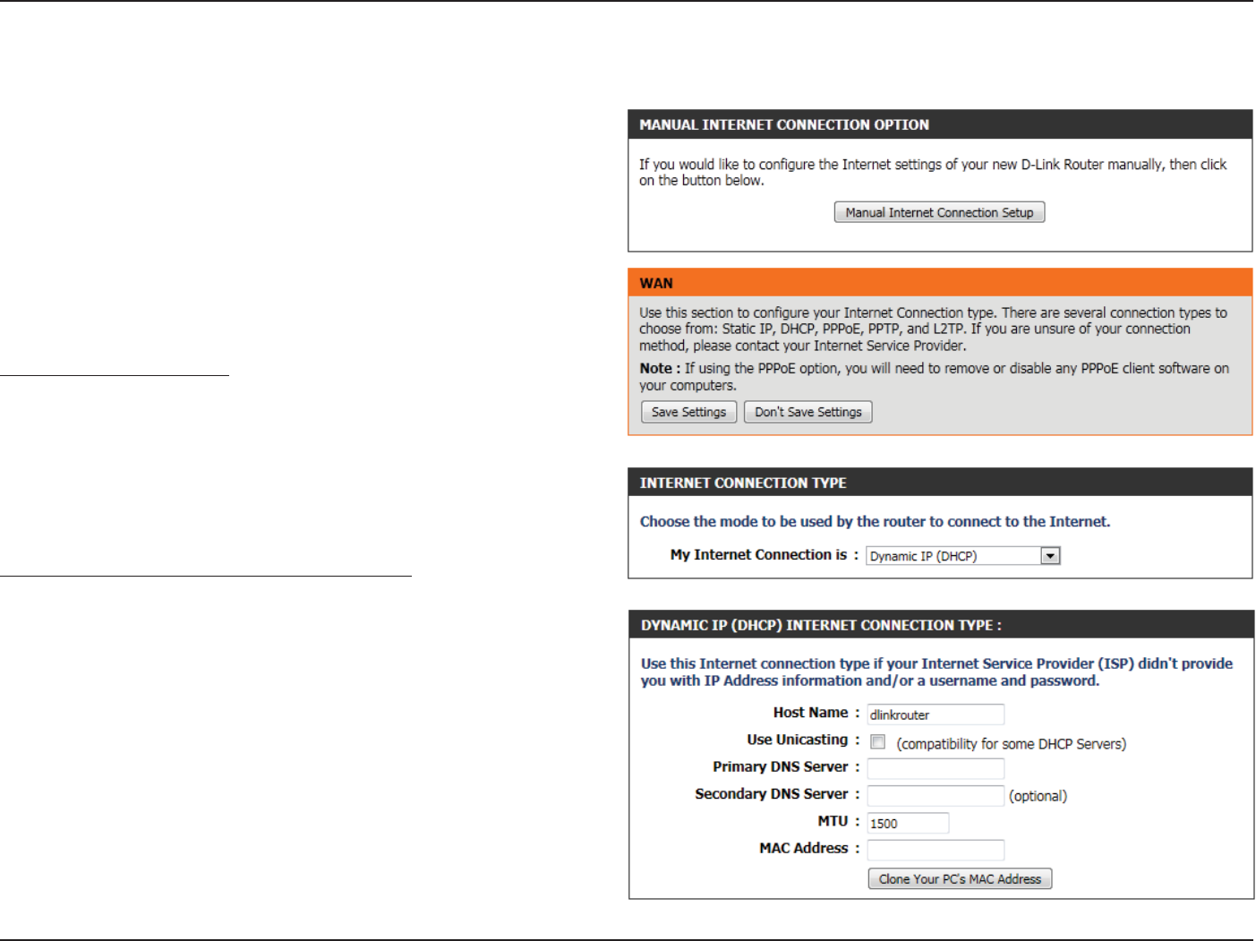
Manual Conguration
At any given point the user can save the conguration done by clicking
on the Save Settings button. If you choose to discard the changes
made, click on the Don’t Save Settings.
Internet Connection Type
In this section, the user can select from a list of Internet Connection
types that can be congured and used on this router. Options to choose
from are Static IP, Dynamic IP, PPPoE, PPTP, L2TP, and DS-Lite.
After selecting a specic Internet Connection type, this page will
automatically refresh and display unique elds to congure related to
the specied Internet Connection type.
My Internet Connection is: Dynamic IP (DHCP)
The default WAN conguration for this router is Dynamic IP (DHCP). This
option allows the router to obtain an IP address automatically from the
device that is connected to the Internet port.
Note: If you’re not sure about the type of Internet Connection you have,
please contact your Internet Service Provider (ISP) for assistance.
Host Name: The Host Name is optional but may be required by
some ISPs. Leave it blank if you are not sure.
Use Unicasting: Tick this option if your ISP uses the unicast method
to provide IP addresses.
Primary DNS: Enter the Primary DNS IP address used.
On this page the user can congure the Internet Connection settings
manually. To access the Manual Internet Connection Setup page, click
on the Manual Internet Connection Setup button. On this page there
are multiple parameters that can be congured regarding the Internet
Connection setup. We’ll discuss them from top to bottom.
Section 3 - Software Conguration
Secondary DNS: Enter the Secondary DNS IP address used. This eld is normally optional. Only one DNS address is required for a functional
Internet connection, but using a second DNS address provides more stability.
MTU: Maximum Transmission Unit - you may need to change the MTU for optimal performance with your specic ISP. 1500 is the
default MTU.
MAC Address: The default MAC Address is set to the Internet port’s physical interface MAC address on the Broadband Router. It is not
recommended that you change the default MAC address unless required by your ISP. You can use the Clone Your PC’s MAC
Address button to replace the Internet port’s MAC address with the MAC address of your Ethernet card.
My Internet Connection is: Static IP
Another Internet Connection type is Static IP. This option allows the user
to manually congure the Static IP Internet Connection type. Normally
the information entered will be supplied by your ISP.
IP Address: Enter the Static IP address provided by the ISP.
Subnet Mask: Enter the Subnet Mask provided by the ISP.
Default
Gateway:
Enter the Gateway IP address provided by the ISP.
Primary DNS: Enter the Primary DNS IP address used.
Secondary DNS: Enter the Secondary DNS IP address used. This
eld is normally optional. Only one DNS address
is required for a functional Internet connection,
but using a second DNS address provides more
stability.
MTU: Maximum Transmission Unit - you may need to
change the MTU for optimal performance with
your specic ISP. 1500 is the default MTU.
MAC Address: The default MAC Address is set to the Internet port’s physical interface MAC address on the Broadband Router. It is not
recommended that you change the default MAC address unless required by your ISP. You can use the Clone Your PC’s MAC
Address button to replace the Internet port’s MAC address with the MAC address of your Ethernet card.
Section 3 - Software Conguration
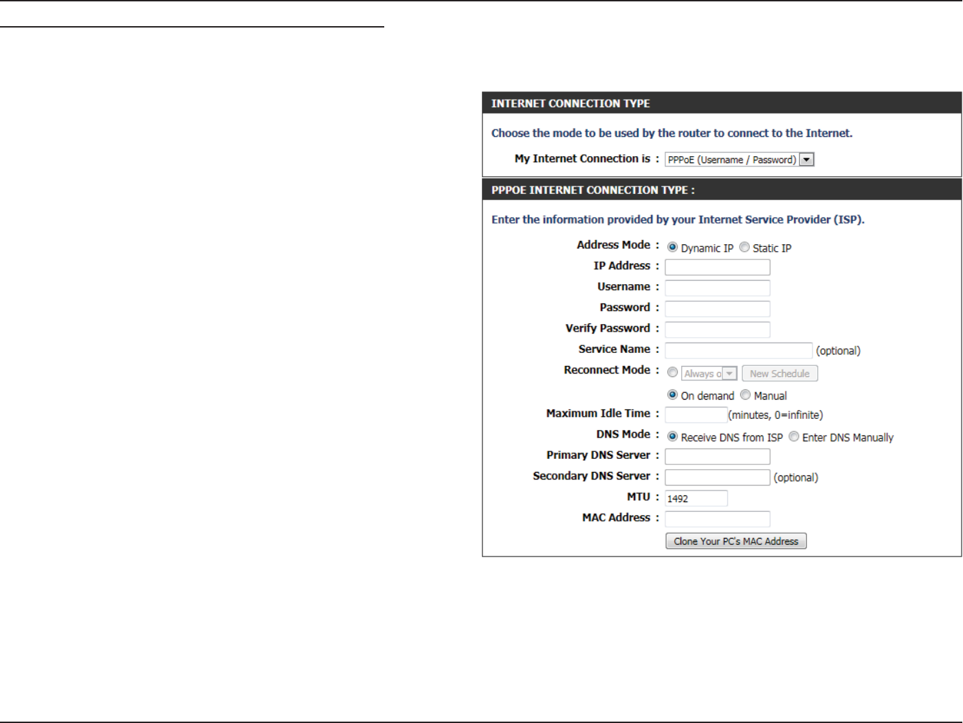
My Internet Connection is: PPPoE (Username/Password)
Another Internet Connection type is PPPoE. This option is typically used if you have a DSL Internet Connection. Make sure to remove the PPPoE
software installed on your computer rst before using this connection type. Most of the information needed for this connection type is provided
to you by your ISP.
Address Mode: Here you can specify whether the Internet
connection requires the use of a Dynamic or Static
IP address. PPPoE usually requires a Dynamic IP
conguration.
IP Address: Enter the PPPoE IP address used here. This option
is only available if Static IP is selected.
Username: Enter the PPPoE account user name used. This
information is given by the ISP.
Password: Enter the PPPoE account password used. This
information is given by the ISP.
Verify Password: Re-enter the PPPoE account password used.
Service Name: This optional eld enables the user to enter a
service name to identify this Internet connection.
Reconnect
Mode:
Use the radio buttons to specify the reconnect
mode. The user can specify a custom schedule
or specify the On Demand, or Manual option. To
specify a custom schedule, use the drop-down
menu to select one of the schedules that has been
dened in the Schedules page. To create a new
schedule, click the New Schedule button to open
the Schedules page. Schedules will be discussed
later.
Maximum Idle
Time:
Enter a maximum idle time during which the Internet connection is maintained during inactivity.
DNS Mode: This option allow the router to obtain the DNS IP addresses from the ISP, when Receive DNS from ISP is selected, or allows the
user to enter the DNS IP address manually, when Enter DNS Manually is selected.
Primary DNS
Server:
Enter the Primary DNS IP address used here.

Section 3 - Software Conguration
Secondary DNS
Server:
Enter the Secondary DNS IP address used here. This eld is normally optional. Only one DNS address is required for a functional
Internet connection, but using a second DNS address provides more stability.
MTU: Maximum Transmission Unit - you may need to change the MTU for optimal performance with your specic ISP. 1492 is the
default MTU.
MAC Address: The default MAC Address is set to the Internet port’s physical interface MAC address on the Broadband Router. It is not
recommended that you change the default MAC address unless required by your ISP. You can use the Clone Your PC’s MAC
Address button to replace the Internet port’s MAC address with the MAC address of your Ethernet card.
Section 3 - Software Conguration
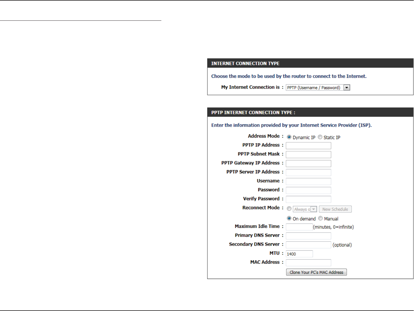
My Internet Connection is: PPTP (Username/Password)
Another Internet Connection type is PPTP. This option is typically used if you have a secure DSL Internet Connection. Most of the information
needed for this connection type is provided to you by your ISP.
Address Mode: Here the user can specify whether this Internet
connection requires the use of a Dynamic or
Static IP address. PPTP usually requires a Dynamic
IP conguration.
PPTP IP Address: Enter the PPTP IP address used. This option is only
available if Static IP is selected.
PPTP Subnet
Mask:
Enter the PPTP Subnet Mask used.
PPTP Gateway IP
Address:
Enter the PPTP Gateway IP address used.
PPTP Server IP
Address:
Enter the PPTP Server IP address used. This is
normally the same a the PPTP Gateway IP address.
Username: Enter the PPTP username used.
Password: Enter the PPTP password used.
Verify Password: Re-enter the PPTP password used.
Reconnect
Mode:
Use the radio buttons to specify the reconnect
mode. The user can specify a custom schedule
or specify the On Demand, or Manual option. To
specify a custom schedule, use the drop-down
menu to select one of the schedules that has
been dened in the Schedules page. To create a
new schedule, click New Schedule to open the
Schedules page. Schedules will be discussed later.
Section 3 - Software Conguration
Maximum Idle
Time:
Enter a maximum idle time during which the Internet connection is maintained during inactivity. To disable this feature,
enable Auto-reconnect.
Primary DNS
Server:
Enter the Primary DNS IP address used.
Secondary DNS
Server:
Enter the Secondary DNS IP address used. This eld is normally optional. Only one DNS address is required for a functional
Internet connection, but using a second DNS address provides more stability.
MTU: Maximum Transmission Unit - you may need to change the MTU for optimal performance with your specic ISP. 1400 is the
default MTU.
MAC Address: The default MAC Address is set to the Internet port’s physical interface MAC address on the Broadband Router. It is not
recommended that you change the default MAC address unless required by your ISP. You can use the Clone Your PC’s MAC
Address button to replace the Internet port’s MAC address with the MAC address of your Ethernet card.
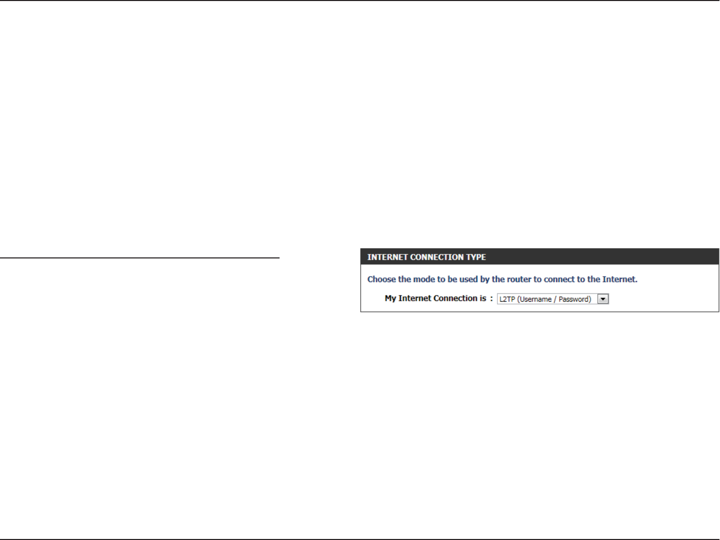
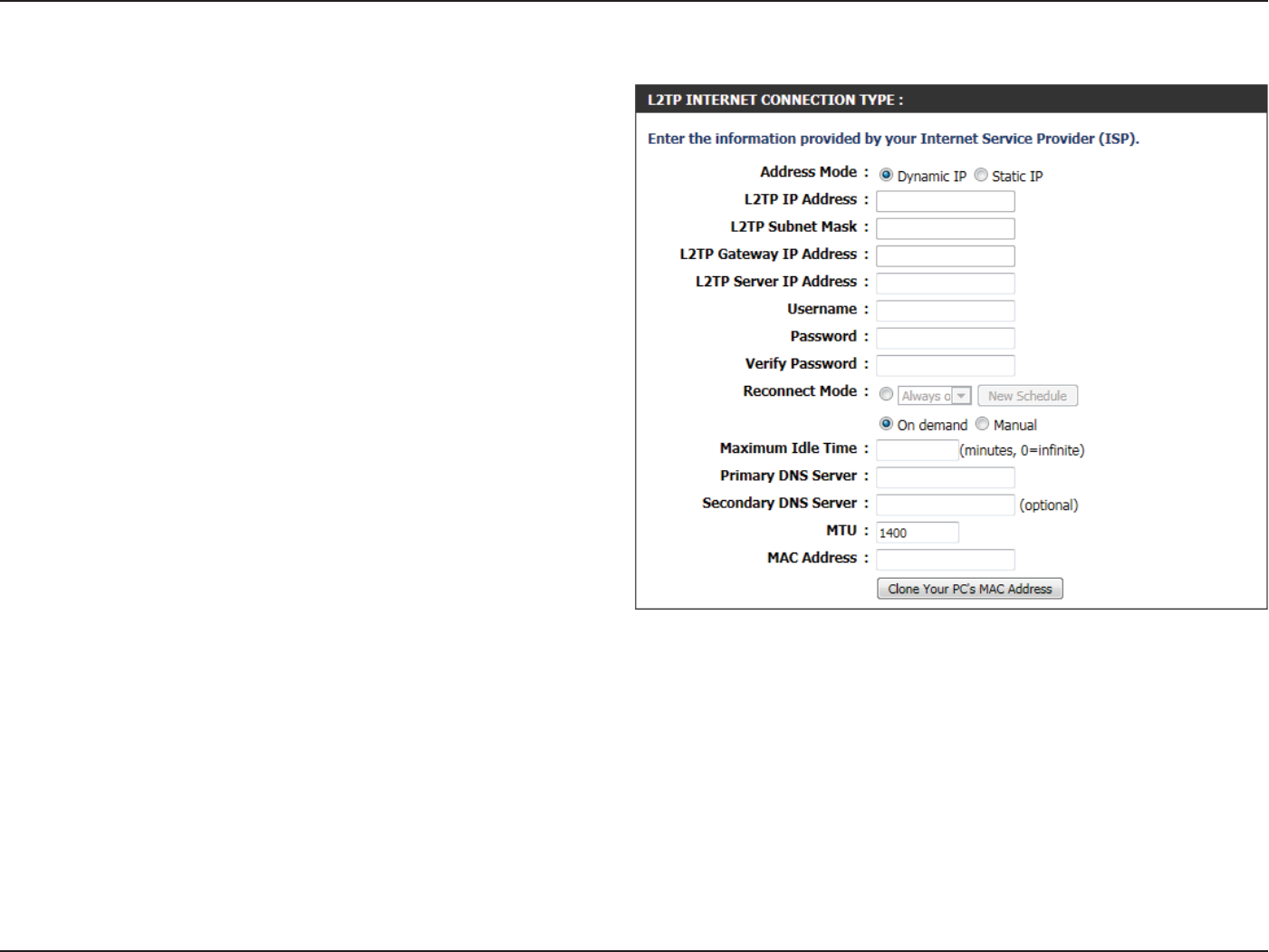
My Internet Connection is: L2TP (Username/Password)
Another Internet Connection type is L2TP. This option is typically used
if you have a secure DSL Internet Connection. Most of the information
needed for this connection type is provided to you by your ISP.
Section 3 - Software Conguration
Address Mode: The user can specify whether this Internet
connection requires the use of a Dynamic or Static
IP address. L2TP usually requires a Dynamic IP
conguration.
L2TP IP Address: Enter the L2TP IP address used. This option is only
available if Static IP is selected.
L2TP Subnet
Mask:
Enter the L2TP Subnet Mask used.
L2TP Gateway IP
Address:
Enter the L2TP Gateway IP address used.
L2TP Server IP
Address:
Enter the L2TP Server IP address used. This is
normally the same as the L2TP Gateway IP address.
Username: Enter the L2TP username used.
Password: Enter the L2TP password used.
Verify Password: Re-enter the L2TP password used.
Reconnect
Mode:
Use the radio buttons to specify the reconnect
mode. The user can specify a custom schedule
or specify the On Demand, or Manual option. To
specify a custom schedule, use the drop-down
menu to select one of the schedules that has been
dened in the Schedules page. To create a new
schedule, click the New Schedule to open the
Schedules page. Schedules will be discussed later.
Maximum Idle
Time:
Enter a maximum idle time during which the Internet connection is maintained during inactivity. To disable this feature,
enable Auto-reconnect.
Primary DNS
Server:
Enter the Primary DNS IP address used.
Secondary DNS
Server:
Enter the Secondary DNS IP address used. This eld is normally optional. Only one DNS address is required for a functional
Internet connection, but using a second DNS address provides more stability.

Section 3 - Software Conguration
MTU: Maximum Transmission Unit - you may need to change the MTU for optimal performance with your specic ISP. 1400 is the
default MTU.
MAC Address: The default MAC Address is set to the Internet port’s physical interface MAC address on the Broadband Router. It is not
recommended that you change the default MAC address unless required by your ISP. You can use the Clone Your PC’s MAC
Address button to replace the Internet port’s MAC address with the MAC address of your Ethernet card.
Section 3 - Software Conguration
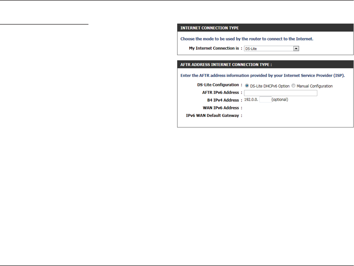
My Internet Connection is: DS-Lite)
Another Internet Connection type is DS-Lite.
After selecting DS-Lite, the following parameters will be available for
conguration:
DS-Lite
Conguration:
Select the DS-Lite DHCPv6 Option to let the router
allocate the AFTR IPv6 address automatically.
Select the Manual Conguration to enter the
AFTR IPv6 address in manually.
AFTR IPv6
Address:
After selecting the Manual Conguration option
above, the user can enter the AFTR IPv6 address
used.
B4 IPv4 Address: Enter the B4 IPv4 address value used.
WAN IPv6
Address:
Once connected, the WAN IPv6 address will be
displayed.
IPv6 WAN
Default Gateway
Once connected, the IPv6 WAN Default Gateway
address will be displayed.
Click on the Save Settings button to accept the changes made.
Click on the Don’t Save Settings button to discard the changes made.
Section 3 - Software Conguration
Wireless Settings
On this page the user can congure the Wireless settings for this device.
There are 3 ways to congure Wireless using this router. Firstly, the user
can choose to make use for the quick and easy Wireless Connection
Setup Wizard. Secondly, the user can choose to make use Wi-Fi Protected
Setup. Lastly, the user can congure the Wireless settings manually.
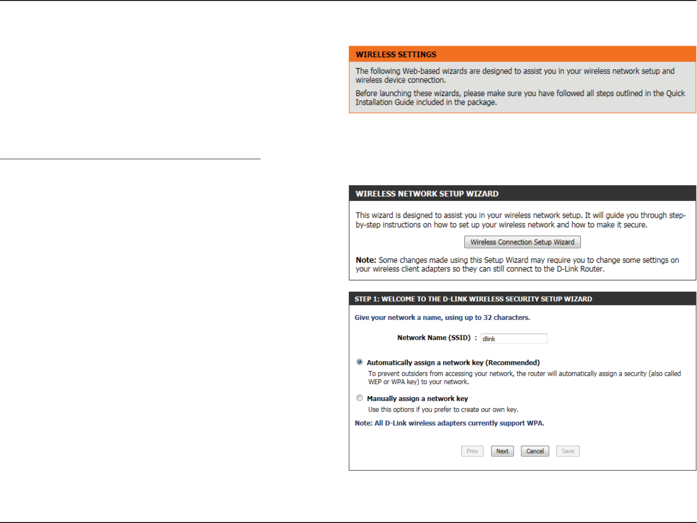
Wireless Settings: Wireless Connection Setup Wizard
The Wireless Connection Setup Wizard is specially designed to assist
basic network users with a simple, step-by-step set of instructions to
congure the wireless settings of this router. It is highly recommended
to customized the wireless network settings to t into your environment
and to add higher security.
To initiate the Wireless Connection Setup Wizard click on the Wireless
Connection Setup Wizard button.
Step 1: In this step, the user must enter a custom Wireless Network
Name or SSID. Enter the new SSID name in the appropriate space
provided. Secondly the user can choose between two wireless security
wizard congurations. The user can select ‘Automatically assign a
network key’, by which the router will automatically generate a WPA/
WPA2 pre-shared key using the TKIP and AES encryption methods; or
the user can select ‘Manually assign a network key’, by which the user
will be prompt to manually enter a WPA/WPA2 pre-shared key using the
TKIP and AES encryption methods.
Click on the Prev button to return to the previous page. Click on the
Next button to continue to the next page. Click on the Cancel button to
discard the changes made and return to the main wireless page.
Section 3 - Software Conguration
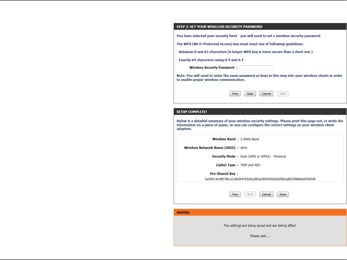
Step 2: This step will only be available if the user selected ‘Manually
assign a network key’ in the previous step. Here the user can manually
enter the WPA/WPA2 pre-shared key in the Wireless Security Password
space provided. The key entered must be between 8 and 63 characters
long. Remember, this key will be used when wireless clients wants to
connect to this device. So please remember this key to prevent future
troubleshooting.
Click on the Prev button to return to the previous page. Click on the
Next button to continue to the next page. Click on the Cancel button to
discard the changes made and return to the main wireless page.
Setup Complete: On this page the user can view the conguration
made and verify whether they are correct.
Click on the Prev button to return to the previous page. Click on the
Cancel button to discard the changes made and return to the main
wireless page. Click on the Save button to accept the changes made.
After click the Save button the device will save the settings made and
return to the main wireless page.
Section 3 - Software Conguration
Wireless Settings: Wi-Fi Protected Setup Wizard
If your Wireless Clients support the WPS connection method, this Wi-Fi
Protected Setup Wizard can be used to initiate a wireless connection
between this device and Wireless clients with a simple click of the WPS
button. The Wi-Fi Protected Setup Wizard is specially designed to assist
basic network users with a simple, step-by-step set of instructions to
connect wireless clients to this router using the WPS method.
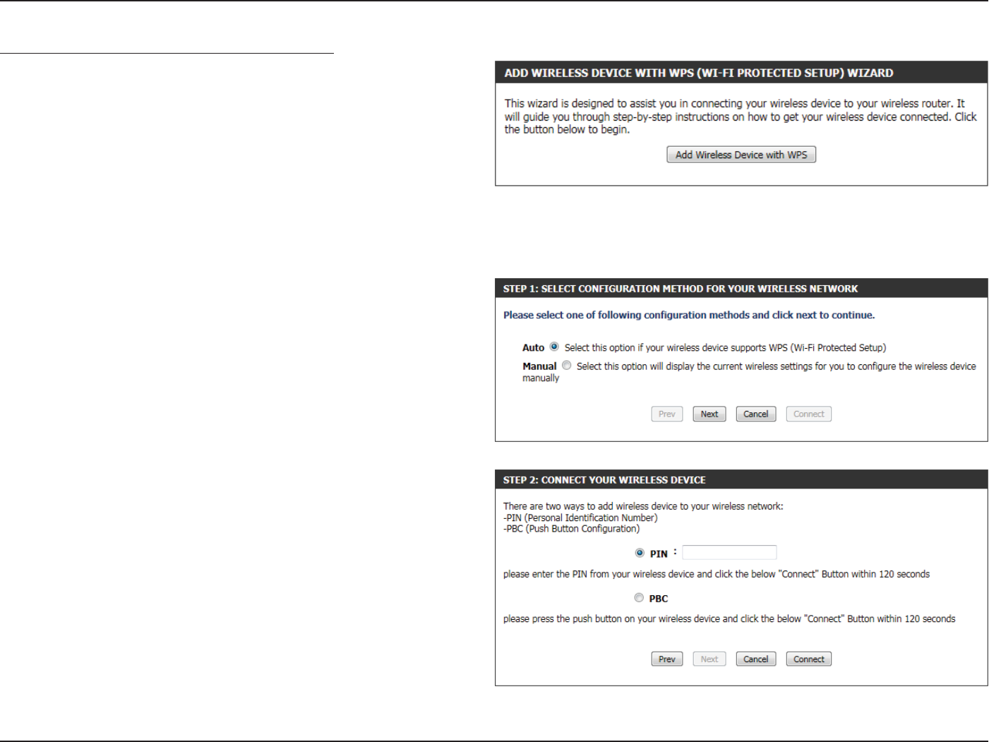
To initiate the Wi-Fi Protected Setup Wizard click on the Add Wireless
Device with WPS button.
Step 1: In this step the user have two options to choose from. You
can choose Auto if the wireless client supports WPS, or Manual if the
wireless client does not support WPS.
Click on the Prev button to return to the previous page. Click on the
Next button to continue to the next page. Click on the Cancel button to
discard the changes made and return to the main wireless page.
Step 2: After selecting Auto, the following page will appear. There are
two ways to add a wireless device, that supports WPS. Firstly, there is the
Personal Identication Number (PIN) method. Using this method will
prompt the user to enter a PIN code. This PIN code should be identical
on the wireless client. Secondly, there is the Push Button Conguration
(PBC) method. Using this method will allow the wireless client to
connect to this device by similarly pressing the PBC button on it.
Click on the Prev button to return to the previous page. Click on the
Next button to continue to the next page. Click on the Cancel button to
discard the changes made and return to the main wireless page.
Section 3 - Software Conguration
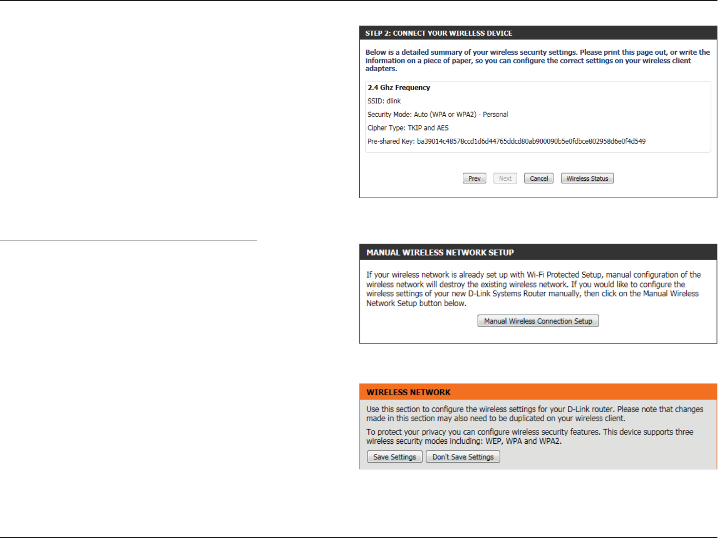
Step 2: After selecting Manual, the following page will appear. On this
page to user can view the wireless conguration of this router. The
wireless clients should congure their wireless settings to be identical
to the settings displayed on this page for a successful connection. This
option is for wireless clients that can’t use the WPS method to connect
to this device.
Click on the Prev button to return to the previous page. Click on the
Next button to continue to the next page. Click on the Cancel button to
discard the changes made and return to the main wireless page. Click
on the Wireless Status button to navigate to the Status > Wireless page
to view what wireless client are connected to this device.
Wireless Settings: Manual Wireless Network Setup
The manual wireless network setup option allows users to congure
the wireless settings of this device manually. This option is for the more
advanced user and includes all parameters that can be congured for
wireless connectivity.
To initiate the Manual Wireless Setup page, click on the Manual Wireless
Connection Setup button.
On this page the user can congure all the parameters related to the
wireless connectivity of this router.
Section 3 - Software Conguration
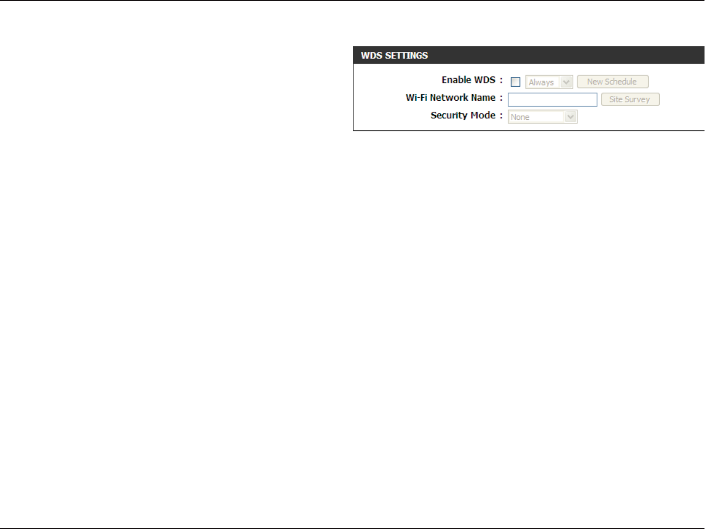
The following parameters will be available for wireless distribution
system (WDS) conguration:
Enable WDS: Check the box to enable the WDS function. If
you do not want to use WDS, uncheck the box
to disable the service. Select the time frame that
you would like your WDS enabled. The schedule
may be set to Always. Any schedule you create will
be available in the drop-down menu. Click New
Schedule to create a new schedule.
Wi-Fi Network
Name:
The Service Set Identier (SSID) is the name of
your wireless network. Click Site Survey to select
an existing SSID or create a name using up to 32
characters. The SSID is case-sensitive.
Security Mode: Select either WEP or WPA-Personal for security
encryption.
Section 3 - Software Conguration
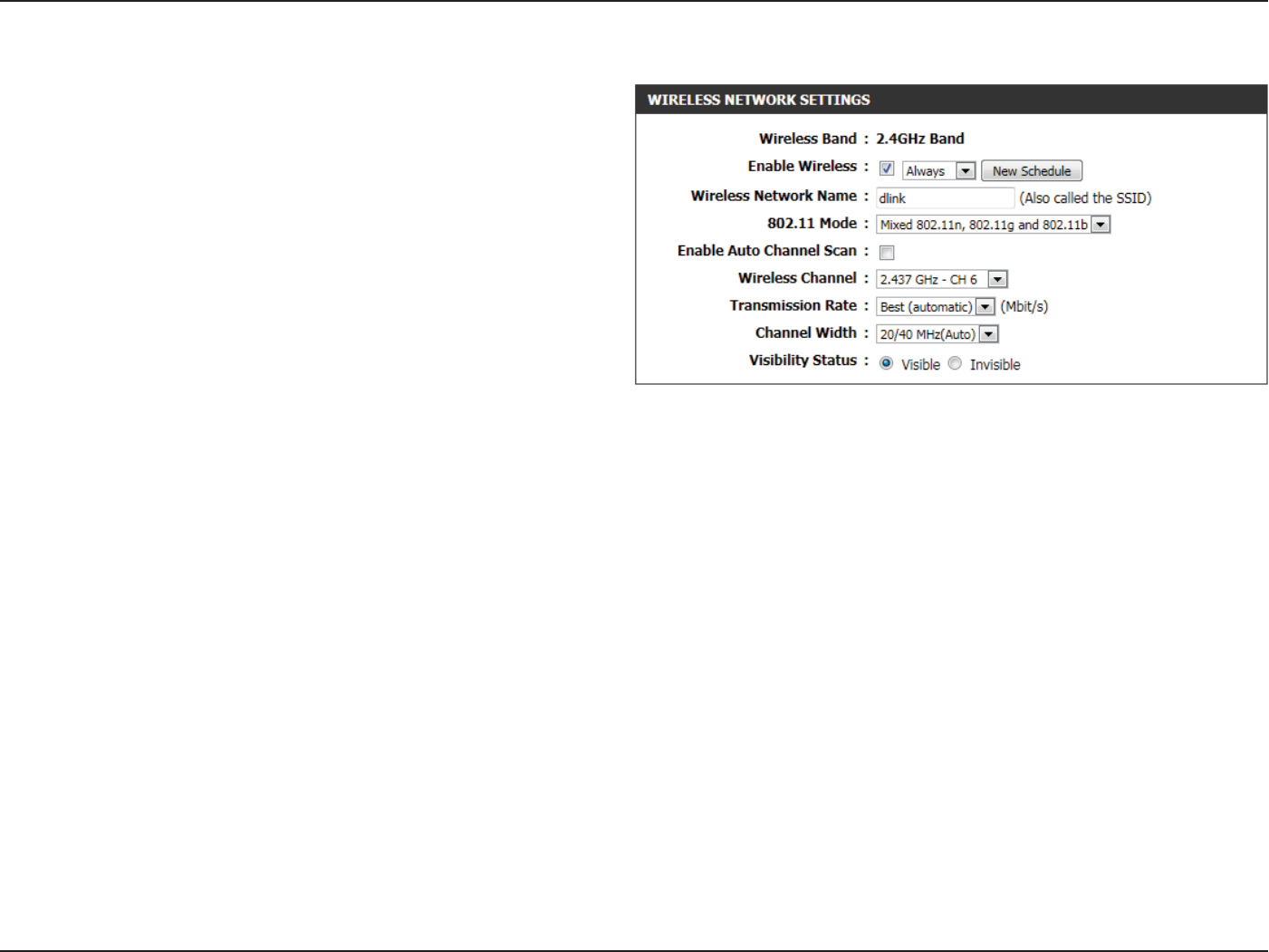
The following parameters will be available for conguration:
Wireless Band: Displays the wireless band being congured. In
this option we nd that the following parameters
will be regarding the 2.4GHz band.
Enable Wireless: Check the box to enable the wireless function. If
you do not want to use wireless, uncheck the box
to disable all the wireless functions. Select the time
frame that you would like your wireless network
enabled. The schedule may be set to Always. Any
schedule you create will be available in the drop-
down menu. Click New Schedule to create a new
schedule.
Wireless
Network Name:
The Service Set Identier (SSID) is the name of
your wireless network. Create a name using up to
32 characters. The SSID is case-sensitive.
802.11 Mode: Here the user can manually select the preferred frequency band to use for this wireless network.
Enable Auto
Channel Scan:
The auto channel selection setting can be selected to allow this device to choose the channel with the least amount of
interference.
Wireless
Channel:
By default the channel is set to 1. The Channel can be changed to t the channel setting for an existing wireless network or to
customize the wireless network. If you enable Auto Channel Selection, this option will be greyed out.
Transmission
Rate:
Select the transmit rate. It is strongly suggested to select Best (Automatic) for best performance.
Channel Width: When using the 802.11n frequency band, the user have an option to choose between a 20MHz or 20/40MHz bandwidth.
Visibility Status: The Invisible option allows you to hide your wireless network. When this option is set to Visible, your wireless network name
is broadcasted to anyone within the range of your signal. If you are not using encryption then they could connect to your
network. When Invisible mode is enabled, you must enter the Wireless Network Name (SSID) on the client manually to connect
to the network.
Section 3 - Software Conguration
By default the wireless security of this router will be disabled. In this
next option the user can enabled or disable wireless security for the
frequency band 2.4GHz. There are two types of encryption that can be
used- WEP or WPA/WPA2.
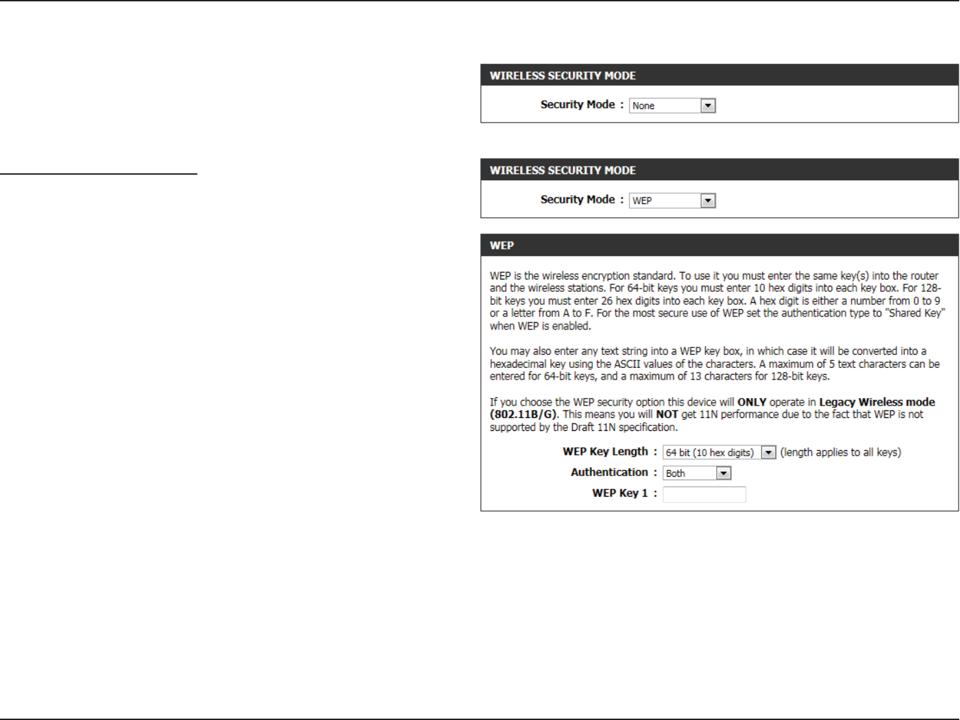
Wireless Security Mode: WEP
Wired Equivalent Privacy (WEP) is the most basic form of encryption
that can be used for wireless networks. Even though it is known as a
‘weak’ security method, it is better than no security at all. Older wireless
adapter sometimes only supports WEP encryption and thus we still nd
this encryption method used today.
WEP Key Length: Here the user can specify to either use a 64Bit or a
128Bit encrypted key.
Authentication: Authentication is a process by which the router
veries the identity of a network device that is
attempting to join the wireless network. There
are two types authentication for this device when
using WEP. Open System allows all wireless devices
to communicate with the router before they are
required to provide the encryption key needed to
gain access to the network. Shared Key requires
any wireless device attempting to communicate
with the router to provide the encryption key
needed to access the network before they are
allowed to communicate with the router.
WEP Key 1: Enter the WEP key used here. For 64-bit keys you must enter 10 hex digits into each key box. For 128-bit keys you must enter
26 hex digits into each key box. A hex digit is either a number from 0 to 9 or a letter from A to F. You may also enter any text
string into a WEP key box, in which case it will be converted into a hexadecimal key using the ASCII values of the characters.
A maximum of 5 text characters can be entered for 64-bit keys, and a maximum of 13 characters for 128-bit keys.
Section 3 - Software Conguration
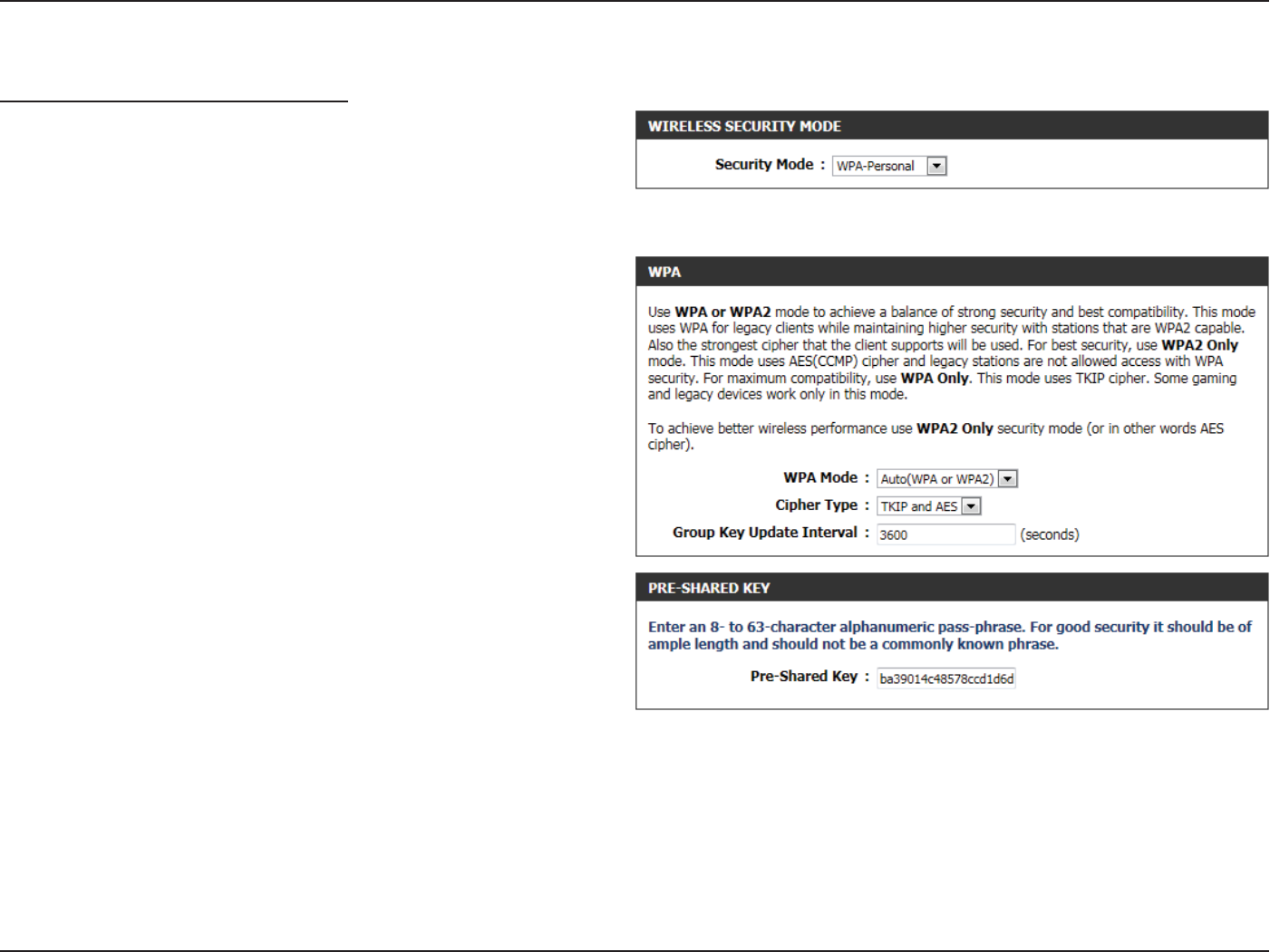
Wireless Security Mode: WPA-Personal
Wi-Fi Protected Access (WPA) is the most advanced and up to date
wireless encryption method used today. This is the recommended
wireless security option. WPA supports two authentication frameworks.
Personal (PSK) and Enterprise (EAP). Personal requires only the use of a
pass-phrase (Shared Secret) for security.
The following parameters will be available for conguration:
WPA Mode: WPA is the older standard; select this option if
the clients that will be used with the router only
support the older standard. WPA2 is the newer
implementation of the stronger IEEE 802.11i
security standard. With the “WPA2” option, the
router tries WPA2 rst, but falls back to WPA if the
client only supports WPA. With the “WPA2 Only”
option, the router associates only with clients that
also support WPA2 security.
Cipher Type: Select the appropriate cipher type to use here.
Options to choose from are Temporal Key Integrity
Protocol (TKIP), Advanced Encryption Standard
(AES), and Both (TKIP and AES).
Group Key
Update Interval:
Enter the amount of time before the group key
used for broadcast and multicast data is changed.
Pre-Shared Key: Enter the shared secret used here. This secret
phrase needs to be the same on all of the wireless
clients for them to be able to connect to the
wireless network successfully.
Section 3 - Software Conguration
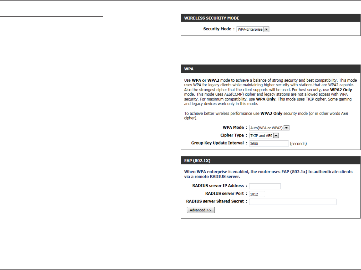
Wireless Security Mode: WPA-Enterprise
Wi-Fi Protected Access (WPA) is the most advanced and up to date
wireless encryption method used today. This is the recommended
wireless security option. WPA supports two authentication frameworks.
Personal (PSK) and Enterprise (EAP). Personal requires only the use of a
pass-phrase (Shared Secret) for security.
WPA Mode: WPA is the older standard; select this option if
the clients that will be used with the router only
support the older standard. WPA2 is the newer
implementation of the stronger IEEE 802.11i
security standard. With the “WPA2” option, the
router tries WPA2 rst, but falls back to WPA if the
client only supports WPA. With the “WPA2 Only”
option, the router associates only with clients that
also support WPA2 security.
Cipher Type: Select the appropriate cipher type to use here.
Options to choose from are Temporal Key Integrity
Protocol (TKIP), Advanced Encryption Standard
(AES), and Both (TKIP and AES).
Group Key
Update Interval:
Enter the amount of time before the group key
used for broadcast and multicast data is changed.
RADIUS Server IP
Address:
When the user chooses to use the EAP
authentication framework, the RADIUS server’s IP
address can be entered here.
RADIUS Server
Port:
When the user chooses to use the EAP
authentication framework, the RADIUS server’s
port number can be entered here.
RADIUS Server
Shared Secret:
Enter the shared secret used here. This secret
phrase needs to be the same on all of the wireless
clients for them to be able to connect to the
wireless network successfully.
Section 3 - Software Conguration
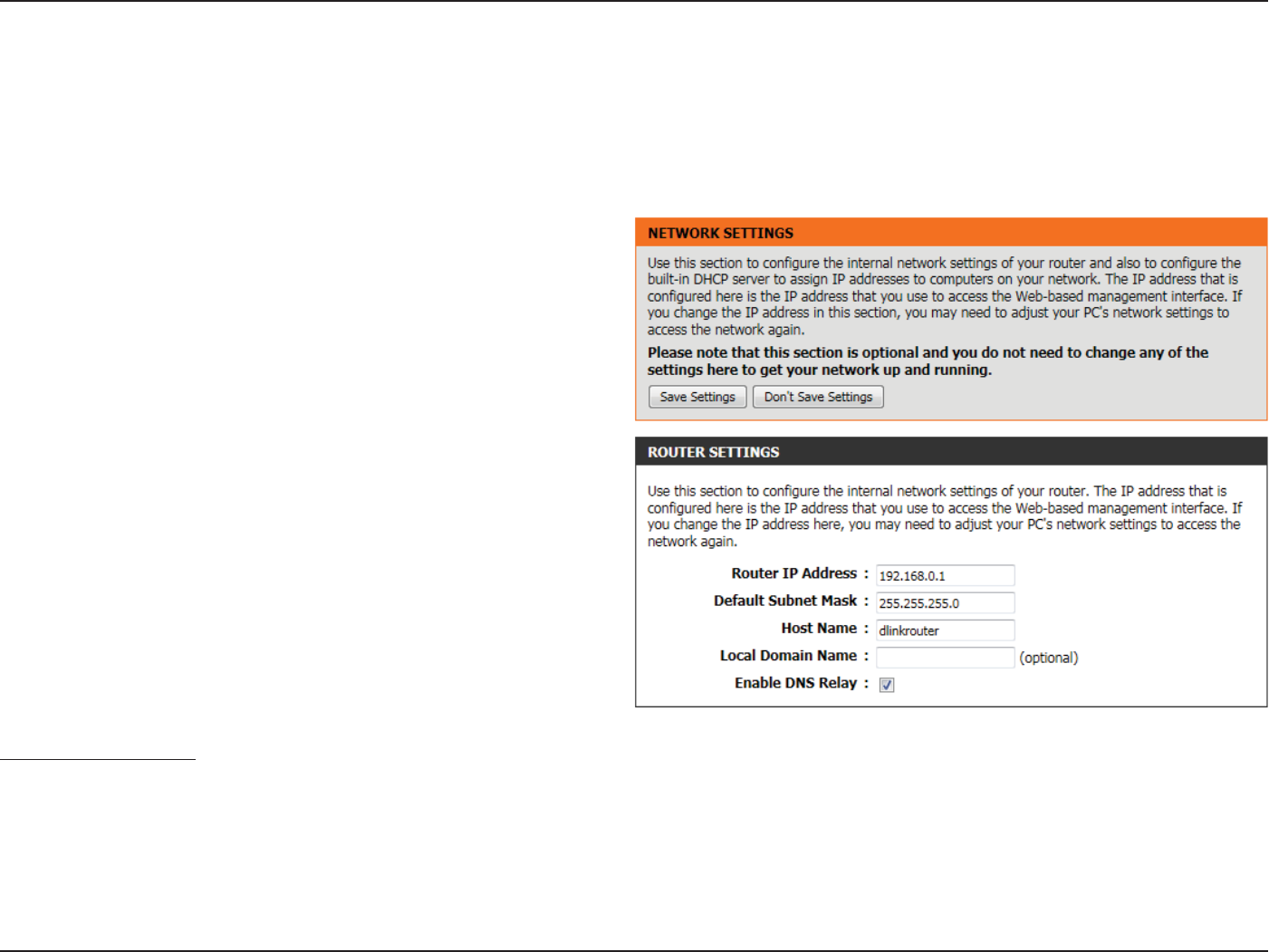
Network Settings
Router IP
Address:
Enter the IP address of the router. The default IP
address is 192.168.0.1. If you change the IP address,
once you click Apply, you will need to enter the
new IP address in your browser to get back into
the conguration utility.
Default Subnet
Mask:
Enter the Subnet Mask. The default subnet mask is
255.255.255.0.
Host Name: Enter a Host Name to identify this device.
Local Domain
Name:
Enter the local domain name used here. (Optional).
Enable DNS
Relay:
Uncheck the box to transfer the DNS server
information from your ISP to your computers. If
checked, your computers will use the router for a
DNS server.
DHCP Server Settings
DHCP stands for Dynamic Host Control Protocol. This device has a built-in DHCP server. The DHCP Server will automatically assign an IP address
to the computers on the LAN/private network. Be sure to set your computers to be DHCP clients by setting their TCP/IP settings to “Obtain an IP
Address Automatically.” When you turn your computers on, they will automatically load the proper TCP/IP settings provided by the router. The
DHCP Server will automatically allocate an unused IP address from the IP address pool to the requesting computer. You must specify the starting
and ending address of the IP address pool.
On this page the user can congure the internal network settings of the router and also able to congure the built-in DHCP server to assign IP
addresses to computers on the network. The IP address that is congured here is the IP address that is used to access the Web-based management
interface. If you change the IP address in this section, you may need to adjust your PC’s network settings to access the network again.
Section 3 - Software Conguration
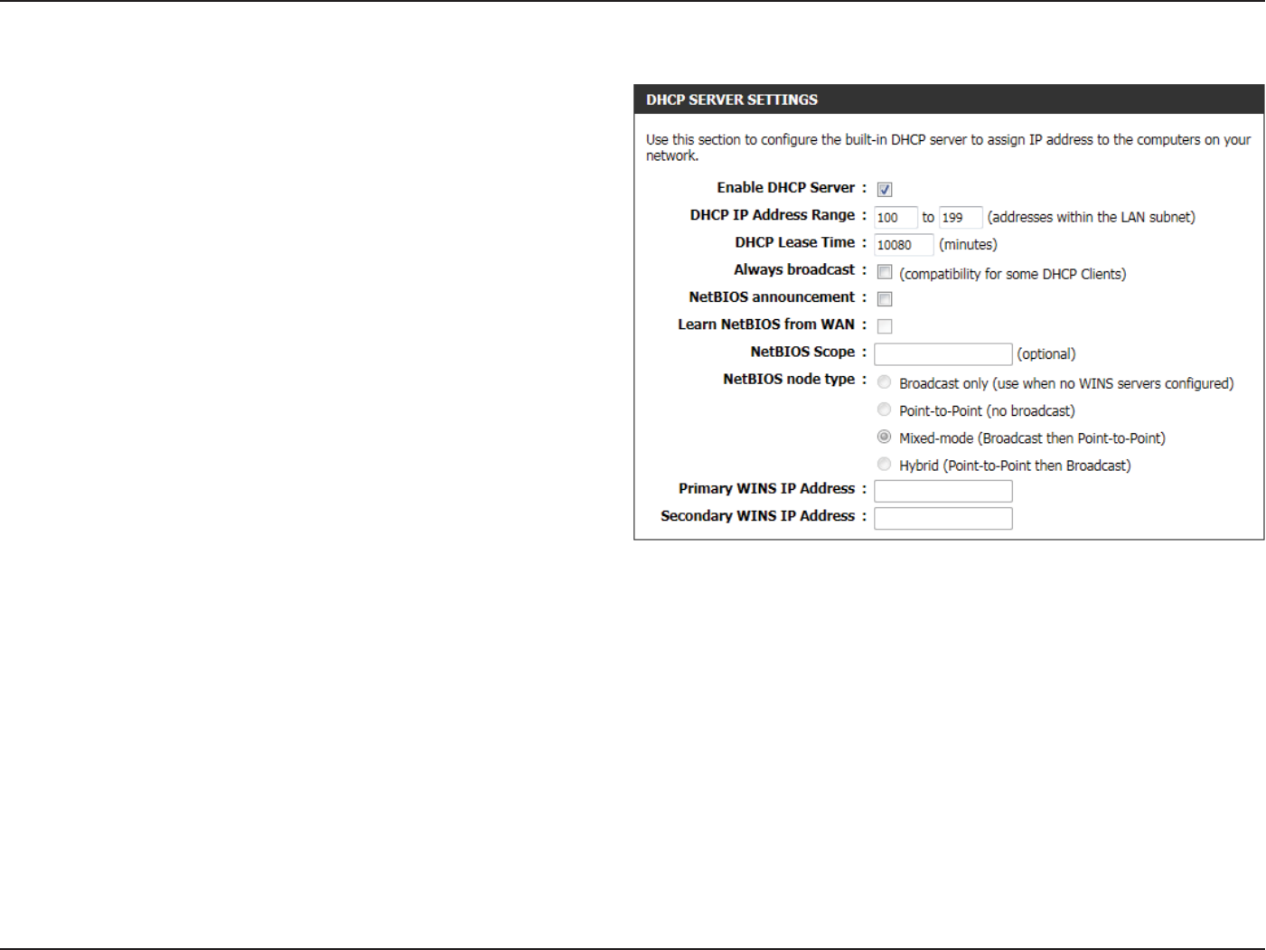
The following parameters will be available for conguration:
Enable DHCP
Server:
Check this box to enable the DHCP server on your
router. Uncheck to disable this function.
DHCP IP Address
Range:
Enter the starting and ending IP addresses for the
DHCP server’s IP assignment.
DHCP Lease
Time:
The length of time for the IP address lease. Enter
the Lease time in minutes.
Always
Broadcast:
If all the computers on the LAN successfully obtain
their IP addresses from the router’s DHCP server
as expected, this option can remain disabled.
However, if one of the computers on the LAN
fails to obtain an IP address from the router’s
DHCP server, it may have an old DHCP client that
incorrectly turns o the broadcast ag of DHCP
packets. Enabling this option will cause the router
to always broadcast its responses to all clients,
thereby working around the problem, at the cost
of increased broadcast trac on the LAN.
NetBIOS
announcement:
Check this box to allow the DHCP Server to oer
NetBIOS conguration settings to the LAN hosts.
NetBIOS allow LAN hosts to discover all other
computers within the network, e.g. within Network
Neighborhood.
Learn NetBIOS
from WAN:
If NetBIOS announcement is switched on, it will cause WINS information to be learned from the WAN side, if available. Turn
this setting o to congure manually.
NetBIOS Scope: This is an advanced setting and is normally left blank. This allows the conguration of a NetBIOS ‘domain’ name under which
network hosts operate. This setting has no eect if the ‘Learn NetBIOS information from WAN’ is activated.

Section 3 - Software Conguration
NetBIOS node
type:
This eld indicates how network hosts are to perform NetBIOS name registration and discovery. H-Node, this indicates a Hybrid-
State of operation. First WINS servers are tried, if any, followed by local network broadcast. This is generally the preferred mode
if you have congured WINS servers. M-Node (default), this indicates a Mixed-Mode of operation. First Broadcast operation
is performed to register hosts and discover other hosts, if broadcast operation fails, WINS servers are tried, if any. This mode
favours broadcast operation which may be preferred if WINS servers are reachable by a slow network link and the majority
of network services such as servers and printers are local to the LAN. P-Node, this indicates to use WINS servers ONLY. This
setting is useful to force all NetBIOS operation to the congured WINS servers. You must have congured at least the primary
WINS server IP to point to a working WINS server. B-Node, this indicates to use local network broadcast ONLY. This setting is
useful where there are no WINS servers available, however, it is preferred you try M-Node operation rst. This setting has no
eect if the ‘Learn NetBIOS information from WAN’ is activated.
Primary WINS
Server IP
address:
Congure the IP address of the preferred WINS server. WINS Servers store information regarding network hosts, allowing
hosts to ‘register’ themselves as well as discover other available hosts, e.g. for use in Network Neighborhood. This setting has
no eect if the ‘Learn NetBIOS information from WAN’ is activated.
Secondary
WINS Server IP
address:
Congure the IP address of the backup WINS server, if any. This setting has no eect if the ‘Learn NetBIOS information from
WAN’ is activated.
Section 3 - Software Conguration
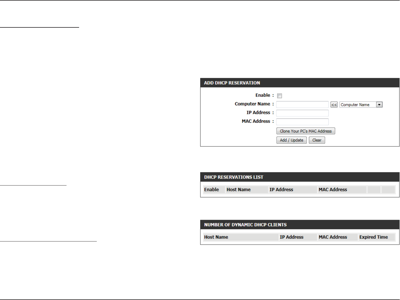
The following parameters will be available for conguration:
Enable: Check this box to enable the reservation.
Computer Name: Enter the computer name. Alternatively, select a
computer that currently has a DHCP lease from
the drop down menu and click << to automatically
populate the Computer Name, IP Address, and
MAC Address elds.
IP Address: Enter the IP address you want to assign to the
computer or device. This IP Address must be
within the DHCP IP Address Range.
MAC Address: Enter the MAC address of the computer or device.
DHCP Reservations List
This shows clients that you have specied to have reserved DHCP
addresses. An entry can be changed by clicking the Edit icon, or deleted
by clicking the Delete icon. When you click the Edit icon, the item is
highlighted, and the ‘Edit DHCP Reservation’ section is activated for
editing.
Number of Dynamic DHCP Clients
In this section you can see what LAN devices are currently leasing IP
addresses.
Add/Edit DHCP Reservation
This option lets you reserve IP addresses, and assign the same IP address to the network device with the specied MAC address any time it requests
an IP address. This is almost the same as when a device has a static IP address except that the device must still request an IP address from the D-Link
router. The D-Link router will provide the device the same IP address every time. DHCP Reservations are helpful for server computers on the local
network that are hosting applications such as Web and FTP. Servers on your network should either use a static IP address or use this option.
Section 3 - Software Conguration
IPv6
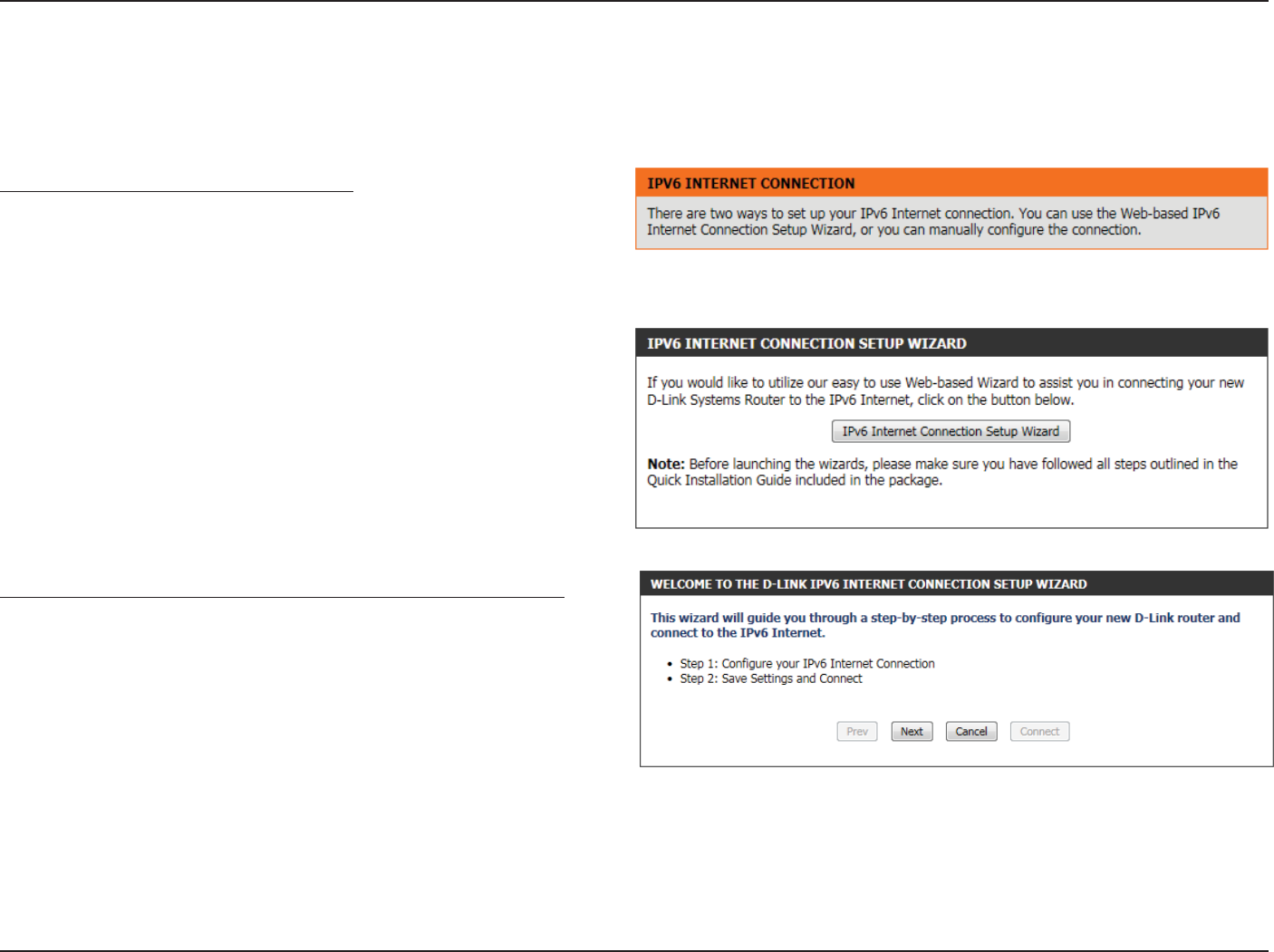
On this page, the user can congure the IPv6 Connection type. There are two ways to set up the IPv6 Internet connection. You can use the Web-
based IPv6 Internet Connection Setup Wizard, or you can manually congure the connection.
IPv6 Internet Connection Setup Wizard
For the beginner user that have not congured a router before, click
on the IPv6 Internet Connection Setup Wizard button and the router
will guide you through a few simple steps to get your network up and
running.
After clicking on the IPv6 Internet Connection Setup Wizard button, this
page will appear.
Welcome to the D-Link IPv6 Internet Connection Setup Wizard
This wizard will guide you through a step-by-step process to congure
your new D-Link router and connect to the IPv6 Internet.
Click Next to continue to the next page. Click Cancel to discard the
changes made and return to the main page.
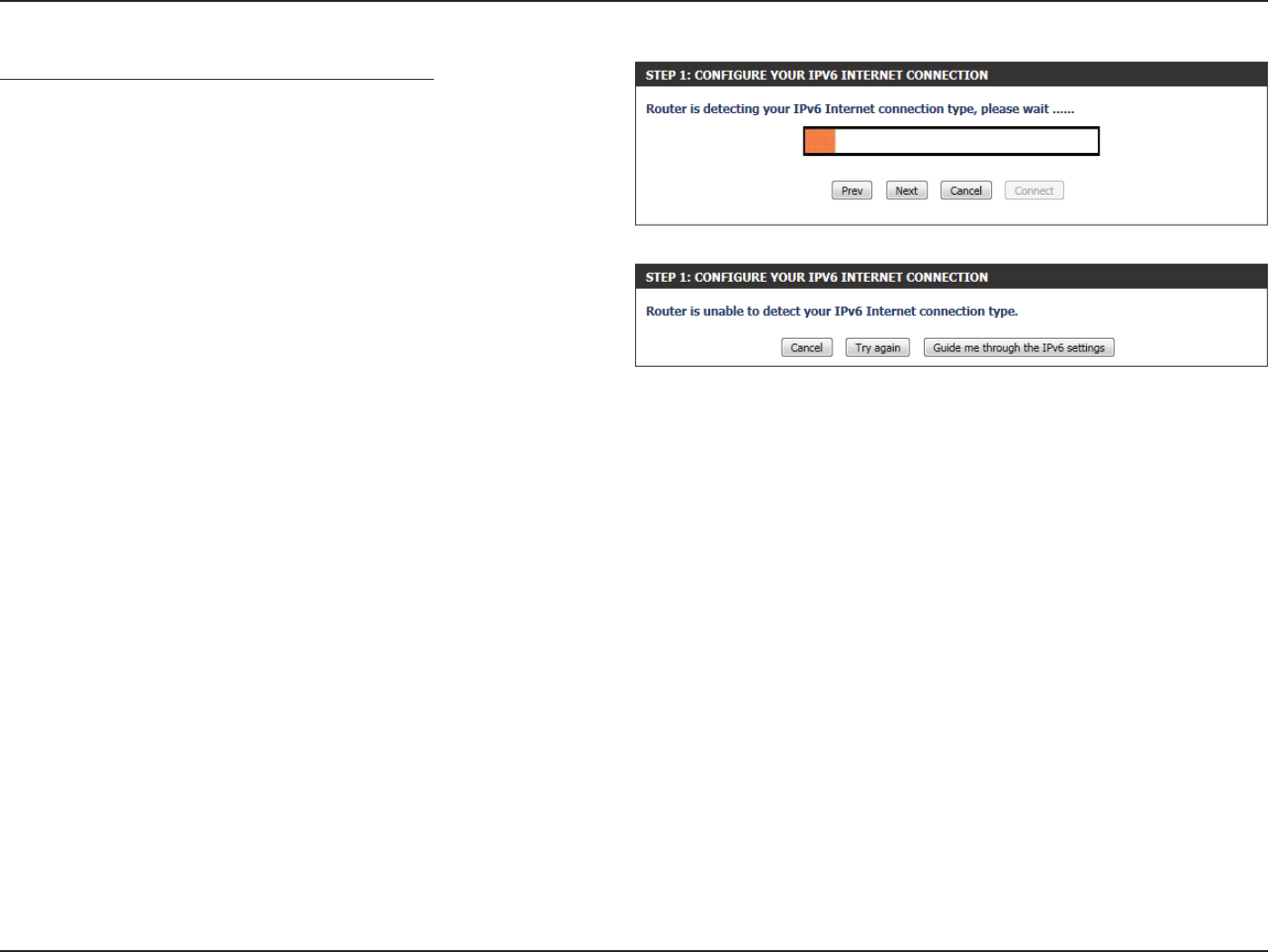
Section 3 - Software Conguration
Step 1: Congure Your IPv6 Internet Connection
The router will try and detect whether its possible to obtain the IPv6
Internet Connection type automatically. If this succeeds then the user
will be guided through the input of the appropriate parameters for the
connection type found.
However, if the automatic detection fails, the user will be prompt to
either Try again or to click on the Guide me through the IPv6 settings
button to initiate the manual continual of the wizard.
Section 3 - Software Conguration
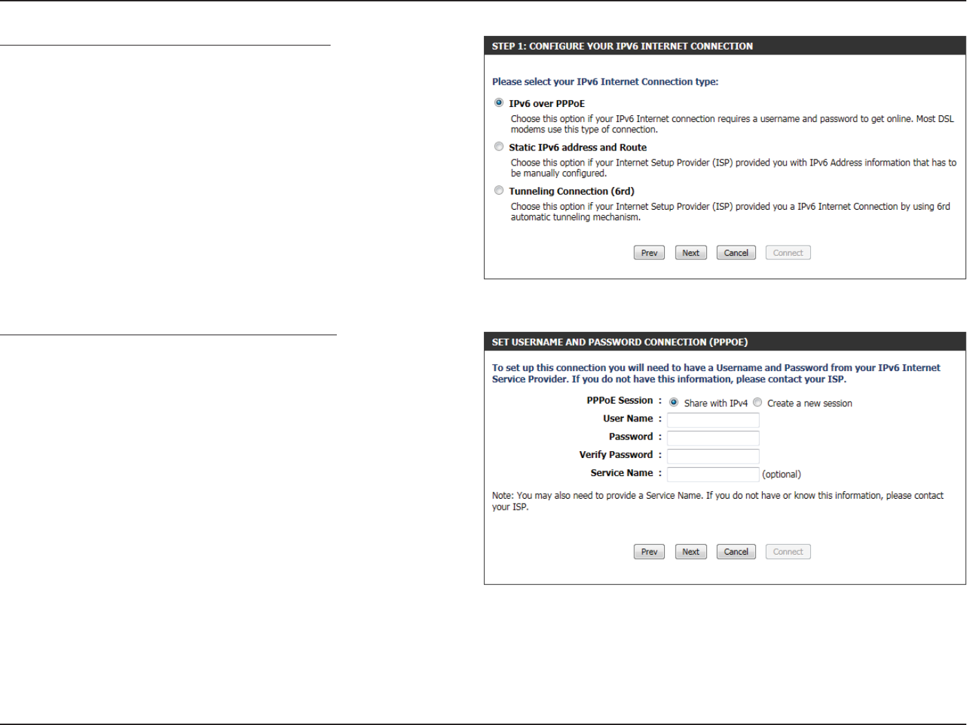
Step 1: Congure Your IPv6 Internet Connection
There are several connection types to choose from. If you are unsure
of your connection method, please contact your IPv6 Internet Service
Provider.
Note: If using the PPPoE option, you will need to ensure that any PPPoE
client software on your computers has been removed or disabled. The 3
options available on this page is IPv6 over PPPoE, Static IPv6 address
and Route, and Tunneling Connection.
Choose the required IPv6 Internet Connection type and click on the
Next button to continue. Click on the Prev button to return to the
previous page. Click on the Cancel button to discard all the changes
made and return to the main page.
Set Username and Password Connection (PPPoE)
After selecting the IPv6 over PPPoE option, the user will be able to
congure the IPv6 Internet connection that requires a username and
password to get online. Most DSL modems use this type of connection.
The following parameters will be available for conguration:
PPPoE Session: Select the PPPoE Session value used here. This
option will state that this connection shares it’s
information with the already congured IPv6
PPPoE connection, or the user can create a new
PPPoE connection here.
User Name: Enter the PPPoE username used here. This
information is obtainable from the ISP.
Password: Enter the PPPoE password used here. This
information is obtainable from the ISP.
Verify Password: Re-enter the PPPoE password used here.
Service Name: Enter the service name for this connection here. This option is optional.
Click on the Next button to continue. Click on the Prev button to return to the previous page.
Click on the Cancel button to discard all the changes made and return to the main page.
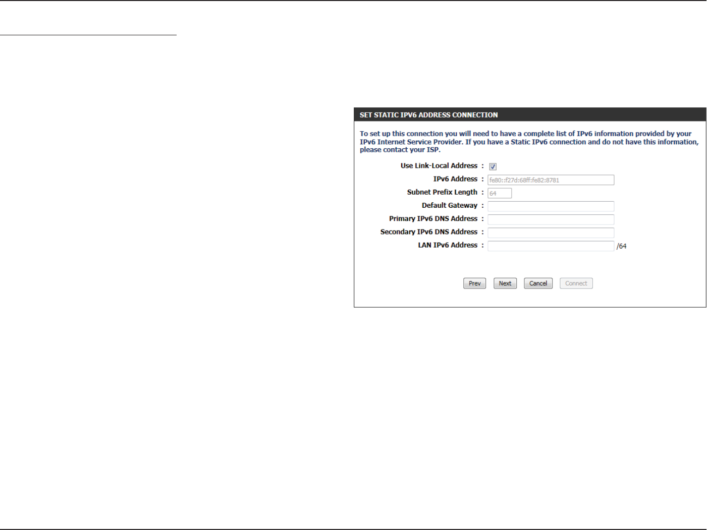
Section 3 - Software Conguration
Use Link-Local
Address:
The Link-local address is used by nodes and
routers when communicating with neighboring
nodes on the same link. This mode enables IPv6-
capable devices to communicate with each other
on the LAN side.
IPv6 Address: Enter the WAN IPv6 address for the router here.
Subnet Prex
Length:
Enter the WAN subnet prex length value used
here.
Set Static IPv6 Address Connection
This mode is used when your ISP provides you with a set IPv6 addresses that does not change. The IPv6 information is manually entered in your
IPv6 conguration settings. You must enter the IPv6 address, Subnet Prex Length, Default Gateway, Primary DNS Server, and Secondary DNS
Server. Your ISP provides you with all this information.
Click on the Next button to continue. Click on the Prev button to return to the previous page.
Click on the Cancel button to discard all the changes made and return to the main page.
Default Gateway
Primary IPv6
DNS Address:
Secondary IPv6
DNS Address:
LAN IPv6
Address:
Enter the WAN default gateway IPv6 address used
here.
Enter the WAN primary DNS Server address used
here.
Enter the WAN secondary DNS Server address used here.
These are the settings of the LAN (Local Area Network) IPv6 interface for the router. The router’s LAN IPv6 Address conguration
is based on the IPv6 Address and Subnet assigned by your ISP. (A subnet with prex /64 is supported in LAN.)
Section 3 - Software Conguration
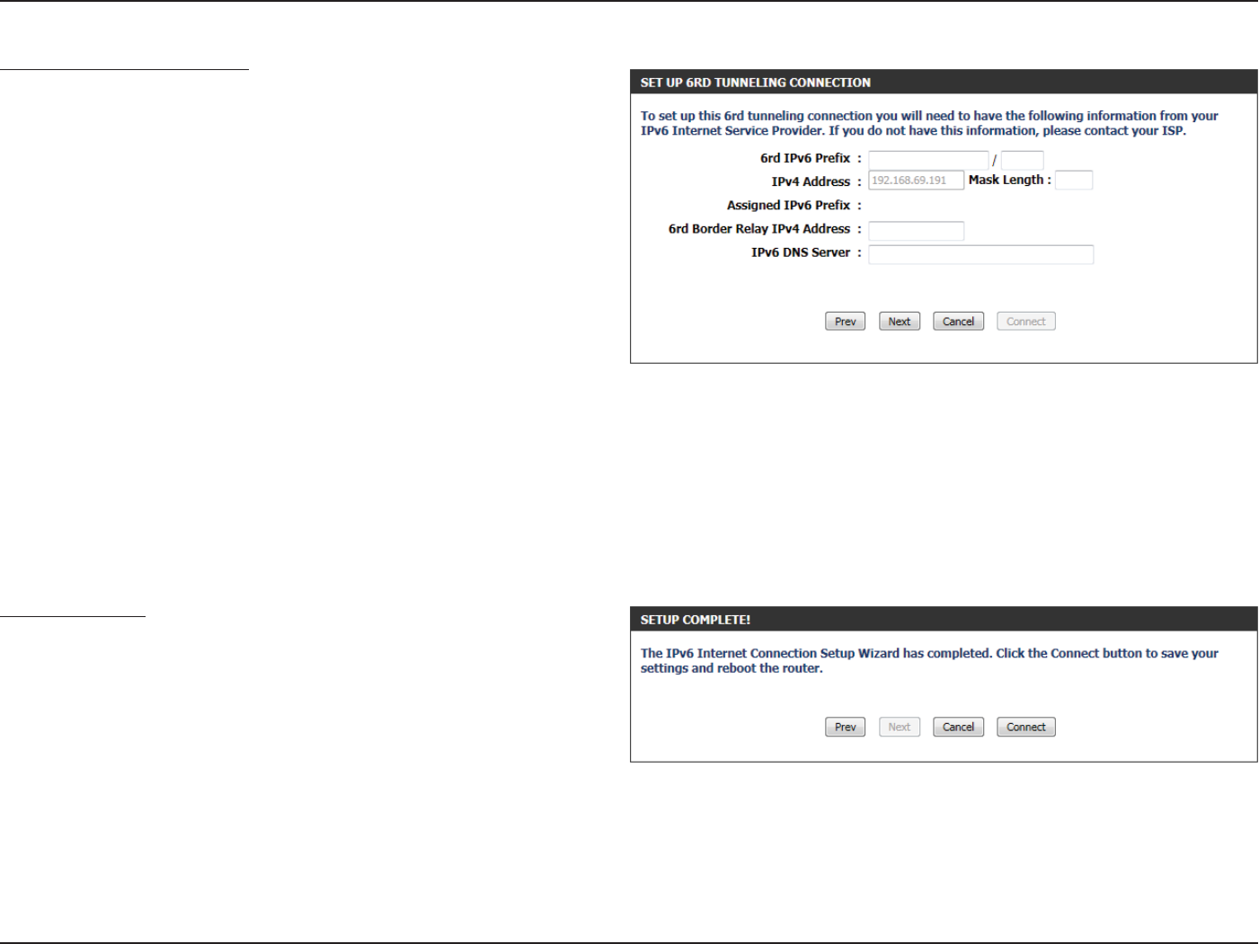
Tunneling Connection (6rd)
After selecting the Tunneling Connection (6rd) option, the user can
congure the IPv6 6rd connection settings.
The following parameters will be available for conguration:
6rd IPv6 Prex: Enter the 6rd IPv6 address and prex value used
here.
IPv4 Address: Enter the IPv4 address used here.
Mask Length: Enter the IPv4 mask length used here.
Assigned IPv6
Prex:
Displays the IPv6 assigned prex value here.
6rd Border Relay
IPv4 Address:
Enter the 6rd border relay IPv4 address used here.
IPv6 DNS Server: Enter the primary DNS Server address used here.
Click on the Next button to continue. Click on the Prev button to return to the previous page.
Click on the Cancel button to discard all the changes made and return to the main page.
Setup Complete
The IPv6 Internet Connection Setup Wizard was completed.
Click on the Connect button to continue. Click on the Prev button to
return to the previous page. Click on the Cancel button to discard all
the changes made and return to the main page.
Section 3 - Software Conguration
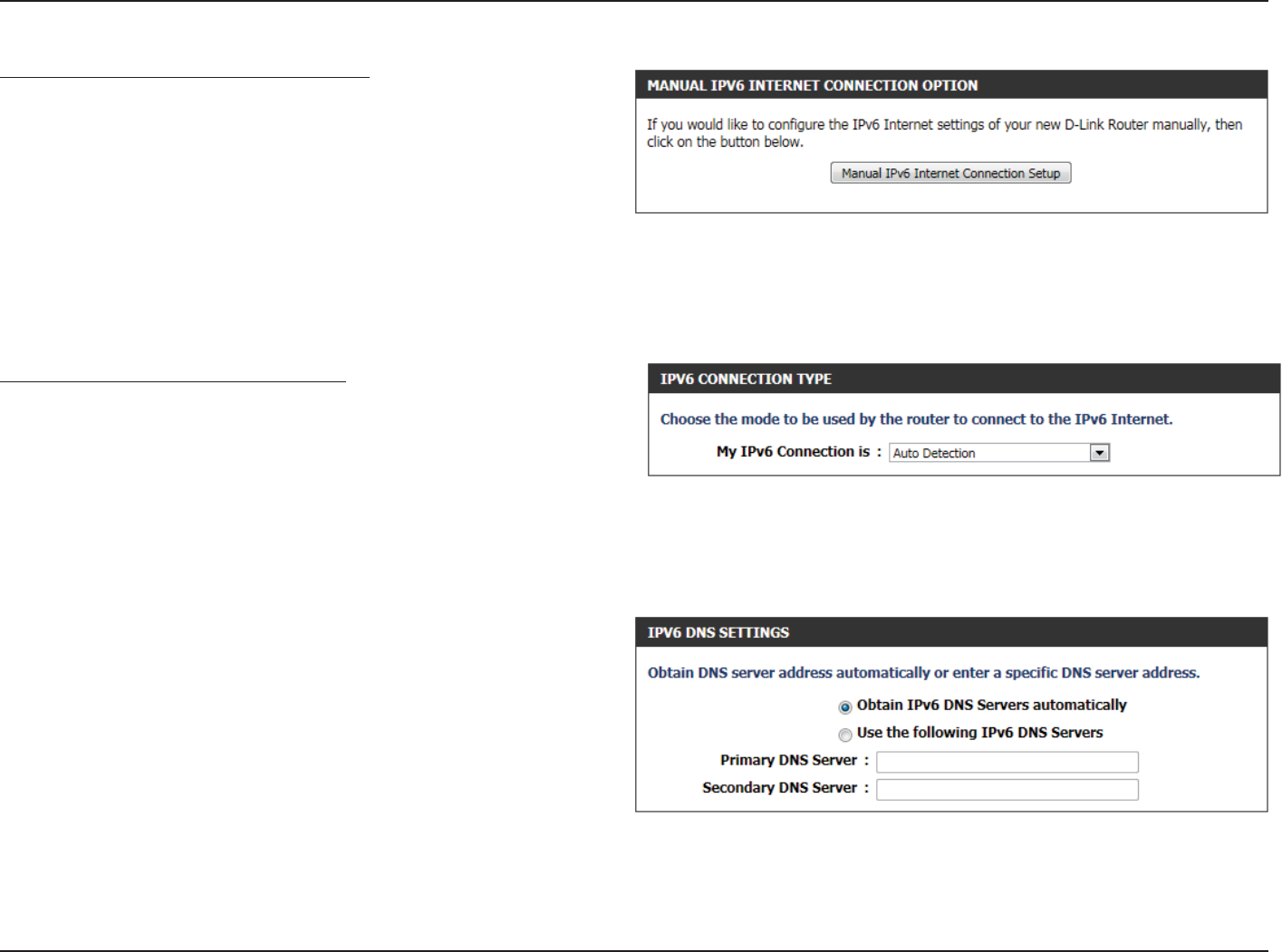
Manual IPv6 Internet Connection Option
For the advanced user that have congured a router before, click on
the Manual IPv6 Internet Connection Setup button to input all the
settings manually.
On this page the user can manually congure the mode that the
Router will use to access an IPv6 Internet connection. There are several
connection types to choose from: Link-local, Static IPv6, DHCPv6,
Stateless Auto-Conguration, PPPoE, IPv6 over IPv4 Tunnel and 6to4.
If you are unsure of your connection method, please contact your IPv6
ISP.
IPv6 Connection Type: Auto Detection
In the following section we’ll discuss the parameters that can be
congured when setting up an Auto Detection (Stateless/DHCPv6)
connection. This is a method of connection where the ISP assigns your
IPv6 address when your router requests one from the ISP’s server. Some
ISP’s require you to make some settings on your side before your router
can connect to the IPv6 Internet.
Obtain IPv6
DNS Server
automatically:
Select this option to obtain the DNS Server
addresses automatically.
Use the
following IPv6
DNS Servers:
Select this option to manually enter the DNS
Server addresses used.
Primary DNS: Enter the primary DNS Server address used here.
Secondary DNS: Enter the secondary DNS Server address used
here.
Section 3 - Software Conguration
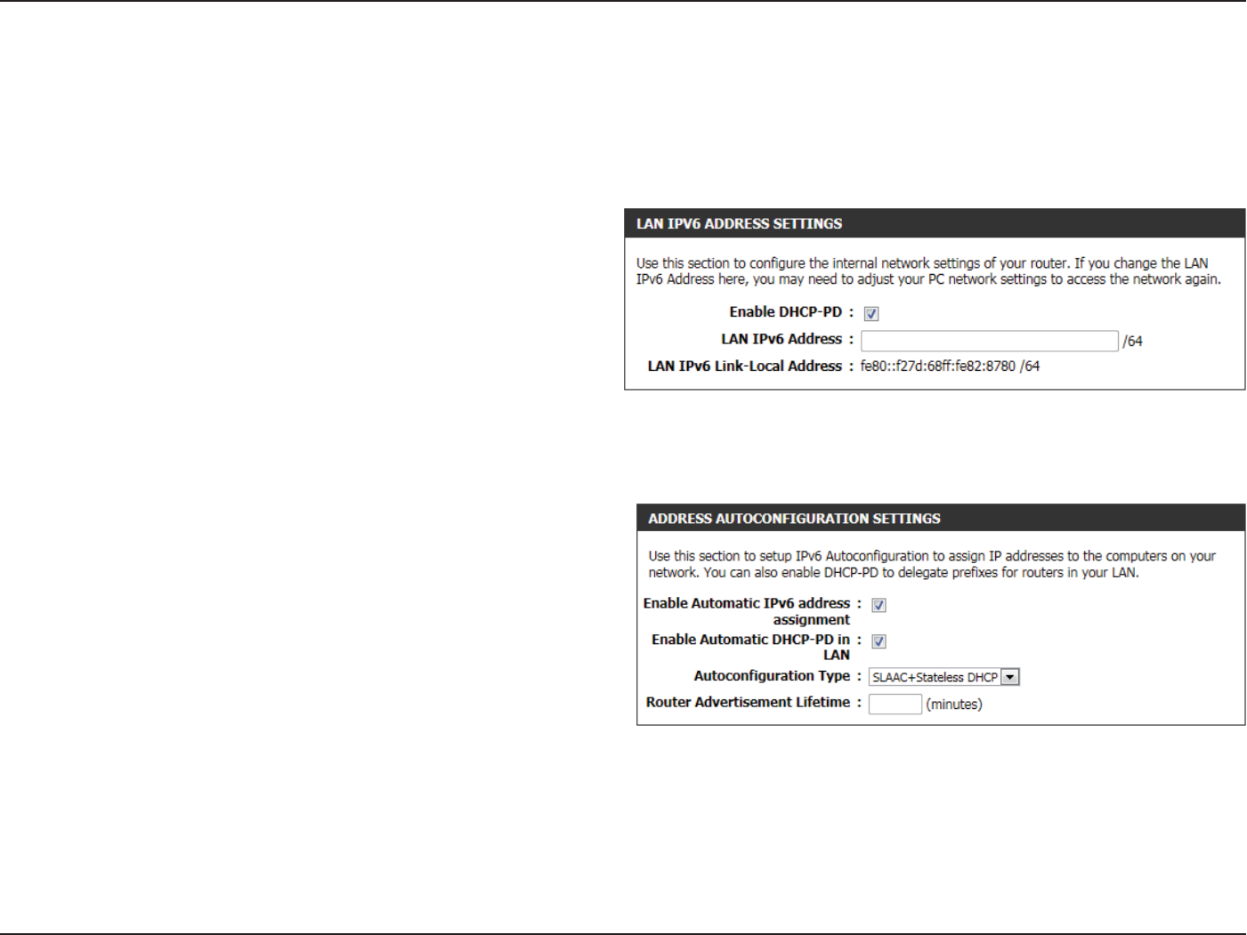
Use the section to congure the internal network settings of your router. The LAN IPv6 Link-Local Address is the IPv6 Address that you use to access
the Web-based management interface. If you change the LAN IPv6 Address here, you may need to adjust your PC’s network settings to access the
network again. DHCP-PD can be used to acquire a IPv6 prex for the LAN interface.
Enable DHCP-
PD:
Select this option to enable DHCP PD.
LAN IPv6
Address:
Enter the LAN IPv6 address used here. This address
must be in the ‘/64’ subnet.
LAN IPv6 Link-
Local Address:
Displays the LAN IPv6 Link-Local address used
here.
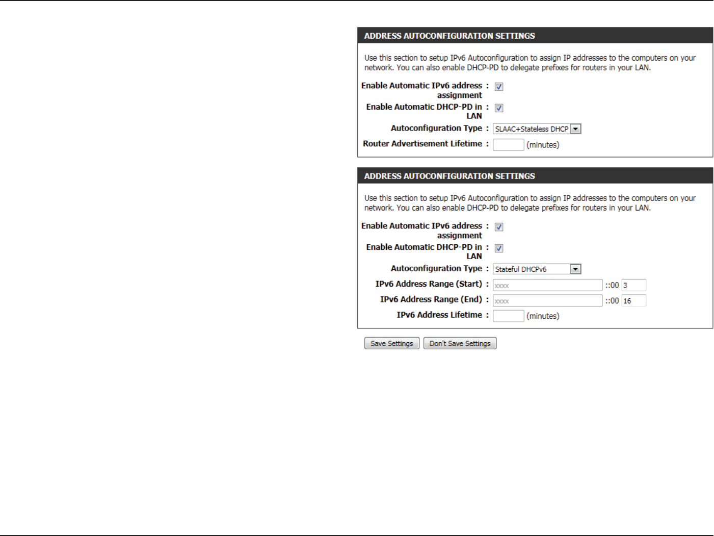
The following parameters will be available for conguration:
Enable Automatic
IPv6 address:
The user can tick this option to enable the auto-
conguration feature.
Enable Automatic
DHCP-PD in LAN:
Autoconguration
Tick this option to enable the automatic DHCP-PD
on the LAN.
Autoconguration
Type:
The user can select the auto-conguration type
used here.
Router
Advertisement
Lifetime:
This option is only available when the auto-
conguration type is set to Stateless. Enter the
router advertisement lifetime value used here.
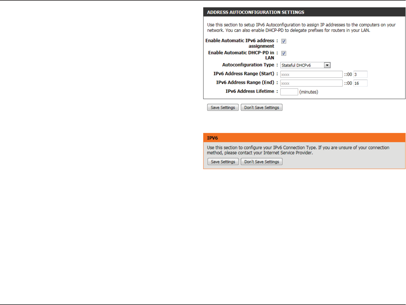
Section 3 - Software Conguration
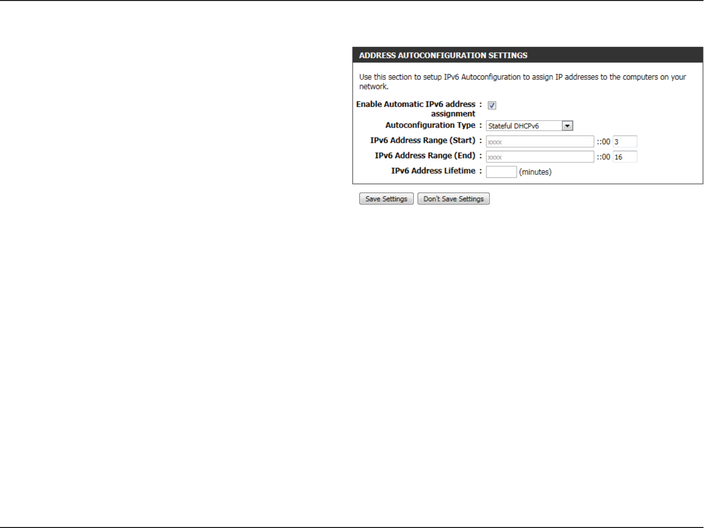
IPv6 Address
Range (Start):
This option is only available when the auto-
conguration type is set to Stateful. Enter the
start IPv6 Address for the DHCPv6 range for your
local computers.
IPv6 Address
Range (End):
This option is only available when the auto-
conguration type is set to Stateful. Enter the end
IPv6 Address for the DHCPv6 range for your local
computers.
IPv6 Address
Lifetime:
This option is only available when the auto-
conguration type is set to Stateful. Enter the IPv6
Address Lifetime (in minutes).
Click on the Save Settings button to accept the changes made.
Click on the Don’t Save Settings button to discard the changes made.
Section 3 - Software Conguration
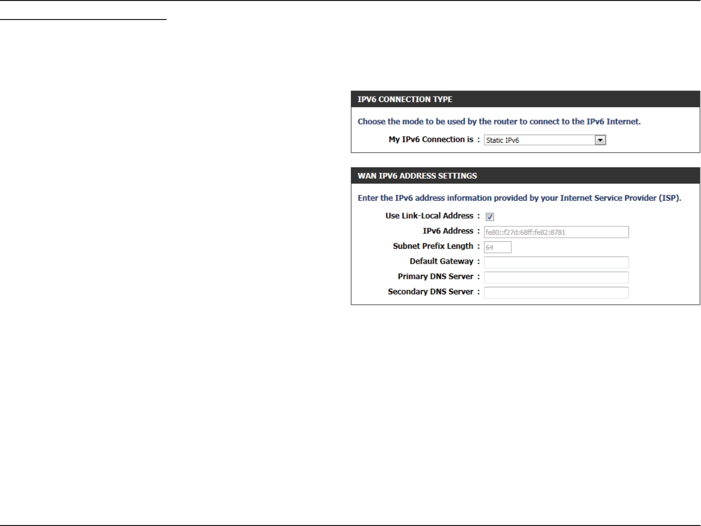
IPv6 Connection Type: Static IPv6
In the following section we’ll discuss the parameters that can be congured when setting up an Static IPv6 connection. This mode is used when
your ISP provides you with a set IPv6 addresses that does not change. The IPv6 information is manually entered in your IPv6 conguration settings.
You must enter the IPv6 address, Subnet Prex Length, Default Gateway, Primary DNS Server, and Secondary DNS Server. Your ISP provides
you with all this information.
The following parameters will be available for conguration:
Use Link-Local
Address:
The Link-local address is used by nodes and
routers when communicating with neighboring
nodes on the same link. This mode enables IPv6-
capable devices to communicate with each other
on the LAN side.
IPv6 Address: Enter the WAN IPv6 address for the router here.
Subnet Prex
Length:
Default
Gateway:
Enter the WAN default gateway IPv6 address used
here.
Primary DNS
Server:
Secondary DNS
Servers:
Enter the WAN primary DNS Server address used
here.
Enter the WAN secondary DNS Server address used
here.
Section 3 - Software Conguration
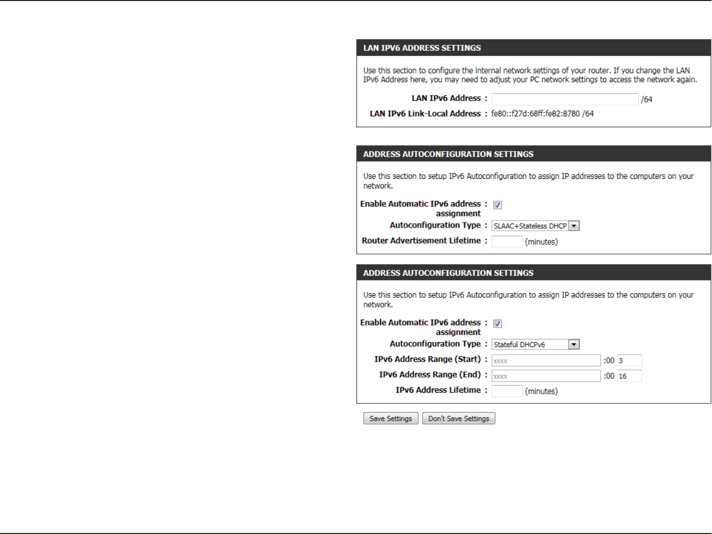
The following parameters will be available for conguration:
LAN IPv6
Address:
Enter the LAN (local) IPv6 address for the router
here.
LAN IPv6 Link-
Local Address:
Displays the Router’s LAN Link-Local Address here.
The following parameters will be available for conguration:
Enable Automatic
IPv6 address:
The user can tick this option to enable the auto-
conguration feature.
Autoconguration
Type:
The user can select the auto-conguration type
used here.
Router
Advertisement
Lifetime:
This option is only available when the auto-
conguration type is set to Stateless. Enter the
router advertisement lifetime value used here.
IPv6 Address
Range (Start):
This option is only available when the auto-
conguration type is set to Stateful. Enter the
start IPv6 Address for the DHCPv6 range for
your local computers.
IPv6 Address
Range (End):
This option is only available when the auto-
conguration type is set to Stateful. Enter the
end IPv6 Address for the DHCPv6 range for your
local computers.
IPv6 Address
Lifetime:
This option is only available when the auto-
conguration type is set to Stateful. Enter the
IPv6 Address Lifetime (in minutes).
Click on the Save Settings button to accept the changes made.
Click on the Don’t Save Settings button to discard the changes made.
Section 3 - Software Conguration
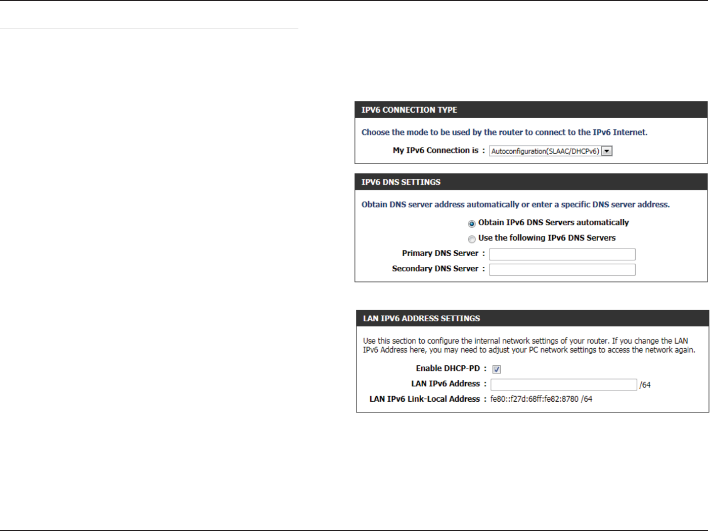
IPv6 Connection Type: Autoconguration (SLAAC/DHCPv6)
In the following section we’ll discuss the parameters that can be congured when setting up an Autoconguration (SLAAC/DHCPv6) connection.
This is a method of connection where the ISP assigns your IPv6 address when your router requests one from the ISP’s server. Some ISP’s require you
to make some settings on your side before your router can connect to the IPv6 Internet.
The following parameters will be available for conguration:
Obtain IPv6
DNS Servers
automatically:
Select this option to obtain the DNS Server
addresses automatically.
Use the
following IPv6
DNS Servers:
Select this option to manually enter the DNS
Server addresses used.
Primary DNS
Server:
Enter the WAN primary DNS Server address used
here.
Secondary DNS
Server:
Enter the WAN secondary DNS Server address
used here.
Enable DHCP-PD:
LAN IPv6 Address:
LAN IPv6 Link-
Local Address:
Select this option to enable DHCP PD.
Enter the LAN IPv6 address used here. This address
must be in the ‘/64’ subnet.
Displays the LAN IPv6 Link-Local address used
here.
Section 3 - Software Conguration
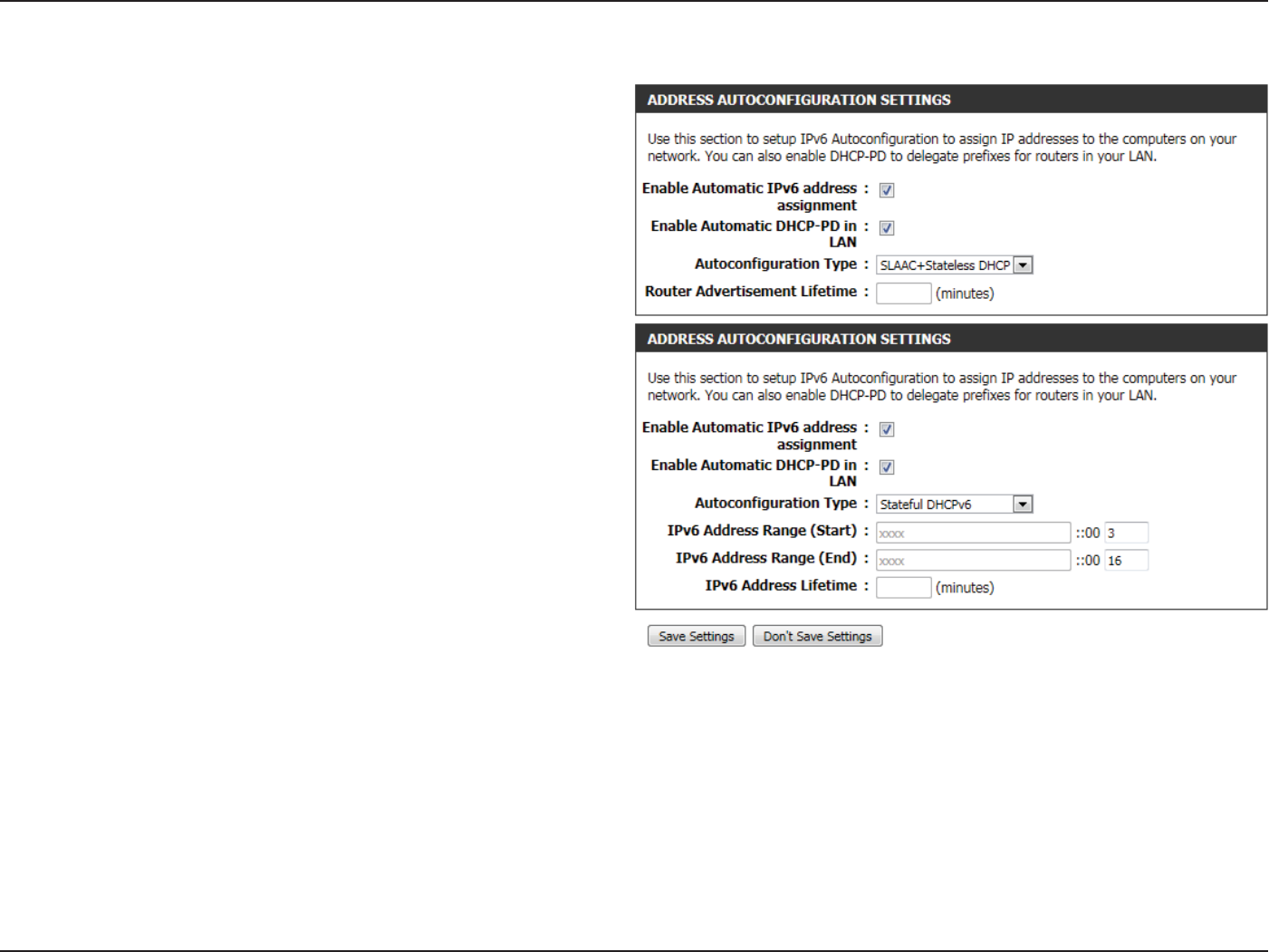
The following parameters will be available for conguration:
Enable Automatic
IPv6 address:
The user can tick this option to enable the auto-
conguration feature.
Enable Automatic
DHCP-PD in LAN:
Tick this option to enable the automatic DHCP-
PD on the LAN.
Autoconguration
Type:
The user can select the auto-conguration type
used here.
Router
Advertisement
Lifetime:
This option is only available when the auto-
conguration type is set to Stateless. Enter the
router advertisement lifetime value used here.
IPv6 Address
Range (Start):
This option is only available when the auto-
conguration type is set to Stateful. Enter the
start IPv6 Address for the DHCPv6 range for your
local computers.
IPv6 Address
Range (End):
This option is only available when the auto-
conguration type is set to Stateful. Enter the
end IPv6 Address for the DHCPv6 range for your
local computers.
IPv6 Address
Lifetime:
This option is only available when the auto-
conguration type is set to Stateful. Enter the
IPv6 Address Lifetime (in minutes).
Click on the Save Settings button to accept the changes made.
Click on the Don’t Save Settings button to discard the changes made.
Section 3 - Software Conguration
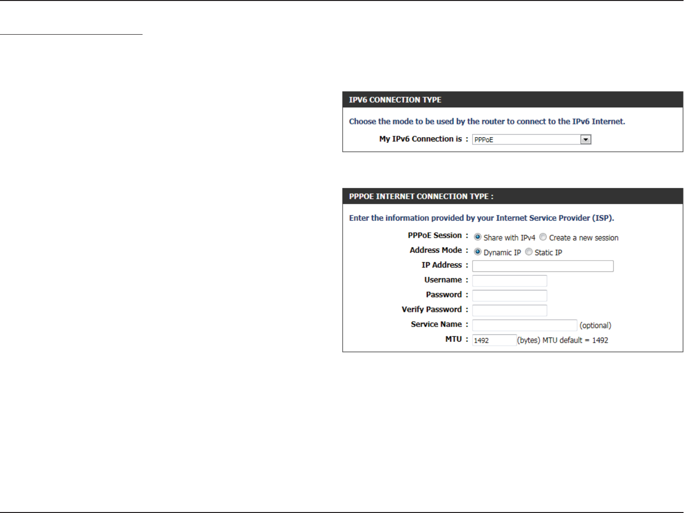
IPv6 Connection Type: PPPoE
Select this option if your ISP requires you to use a PPPoE (Point to Point Protocol over Ethernet) connection to IPv6 Internet. DSL providers typically
use this option. This method of connection requires you to enter a Username and Password (provided by your Internet Service Provider) to gain
access to the IPv6 Internet. The supported authentication protocols are PAP and CHAP.
The following parameters will be available for conguration:
PPPoE Session: Select the PPPoE Session value used here. This
option will state that this connection shares it’s
information with the already congured IPv6
PPPoE connection, or the user can create a new
PPPoE connection here.
Address Mode: Select the appropriate address mode used here.
Select Dynamic IP if the ISP’s servers assign the
router’s WAN IPv6 address upon establishing a
connection. If your ISP has assigned a xed IPv6
address, select Static IP. The ISP provides the value
for the IPv6 Address.
IP Address: Enter the ISP PPPoE IP address in here.
Username: Enter the PPPoE username used here. This information is obtainable from the ISP.
Password: Enter the PPPoE password used here. This information is obtainable from the ISP.
Verify Password: Re-enter the PPPoE password used here.
Service Name: Enter the service name for this connection here. This option is optional.
MTU: Enter the MTU value used here. The default value is 1492.
Section 3 - Software Conguration
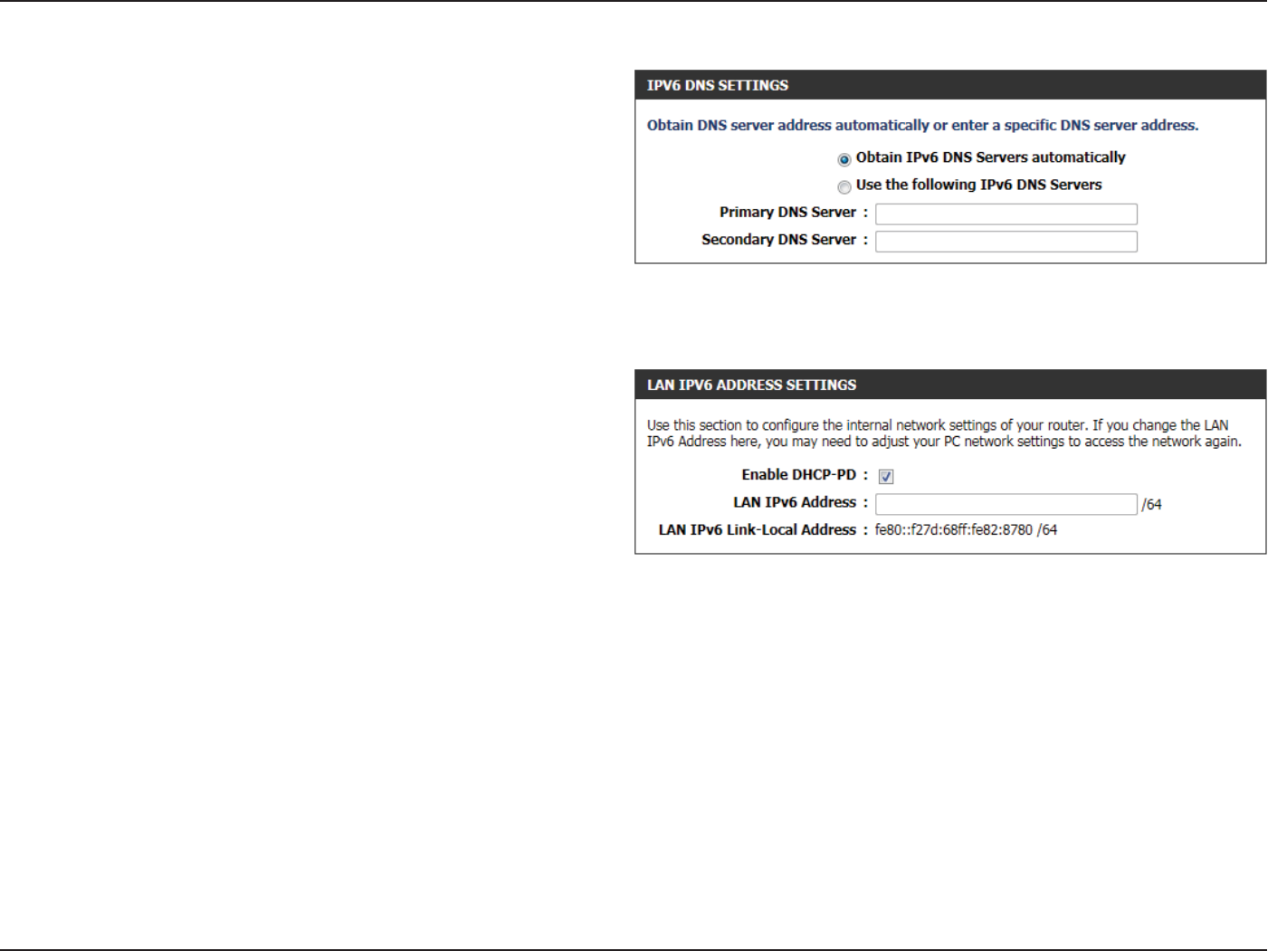
The following parameters will be available for conguration:
Obtain IPv6: Select this option to obtain the DNS Server
addresses automatically.
Use IPv6: Select this option to manually enter the DNS
Server addresses used.
Primary DNS: Enter the primary DNS Server address used here.
Secondary DNS: Enter the secondary DNS Server address used
here.
The following parameters will be available for conguration:
Enable DHCP-
PD:
Select this option to enable DHCP PD.
LAN IPv6
Address:
Enter the LAN IPv6 address used here. This address
must be in the ‘/64’ subnet.
LAN IPv6 Link-
Local Address:
Displays the LAN IPv6 Link-Local address used
here.
Section 3 - Software Conguration
The following parameters will be available for conguration:
Enable Automatic
IPv6 address:
The user can tick this option to enable the
auto-conguration feature.
Enable Automatic
DHCP-PD in LAN:
Tick this option to enable the automatic DHCP-
PD on the LAN.
Autoconguration
Type:
The user can select the auto-conguration
type used here.
Router
Advertisement
Lifetime:
This option is only available when the auto-
conguration type is set to Stateless. Enter the
router advertisement lifetime value used here.
IPv6 Address Range
(Start):
This option is only available when the auto-
conguration type is set to Stateful. Enter the
start IPv6 Address for the DHCPv6 range for
your local computers.
IPv6 Address Range
(End):
This option is only available when the auto-
conguration type is set to Stateful. Enter the
end IPv6 Address for the DHCPv6 range for
your local computers.
IPv6 Address
Lifetime:
This option is only available when the auto-
conguration type is set to Stateful. Enter the
IPv6 Address Lifetime (in minutes).
Click on the Save Settings button to accept the changes made.
Click on the Don’t Save Settings button to discard the changes made.
Section 3 - Software Conguration
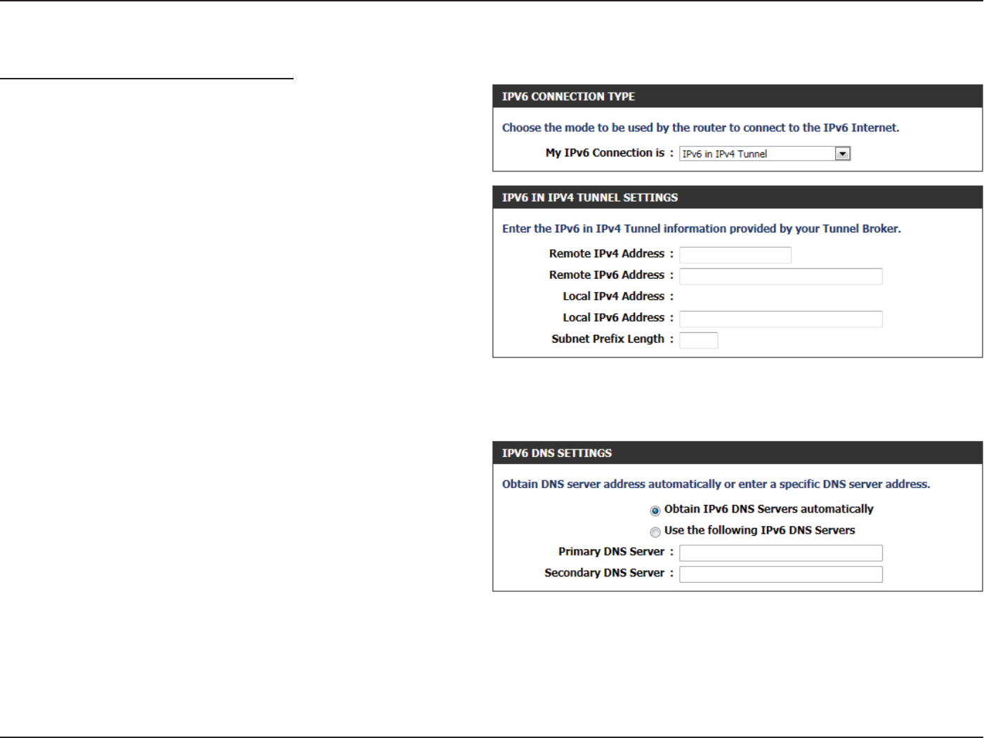
IPv6 Connection Type: IPv6 in IPv4 Tunnel
In section to the user can congure the IPv6 connection to run in IPv4
Tunnel mode. IPv6 over IPv4 tunneling encapsulates IPv6 packets in
IPv4 packets so that IPv6 packets can be sent over an IPv4 infrastructure.
The following parameters will be available for conguration:
Remote IPv4
Address:
Enter the remote IPv4 address used here.
Remote IPv6
Address:
Enter the remote IPv6 address used here.
Local IPv4
Address:
Enter the local IPv4 address used here.
Local IPv6
Address:
Enter the local IPv6 address used here.
Subnet Prex
Length:
Enter the Subnet prex length value used here.
The following parameters will be available for conguration:
Obtain IPv6
DNS Servers
automatically:
Select this option to obtain the DNS Server
addresses automatically.
Use the
following IPv6
DNS Servers:
Select this option to manually enter the DNS
Server addresses used.
Primary DNS
Server:
Enter the WAN primary DNS Server address used here.
Secondary DNS
Server:
Enter the WAN secondary DNS Server address used here.
Section 3 - Software Conguration
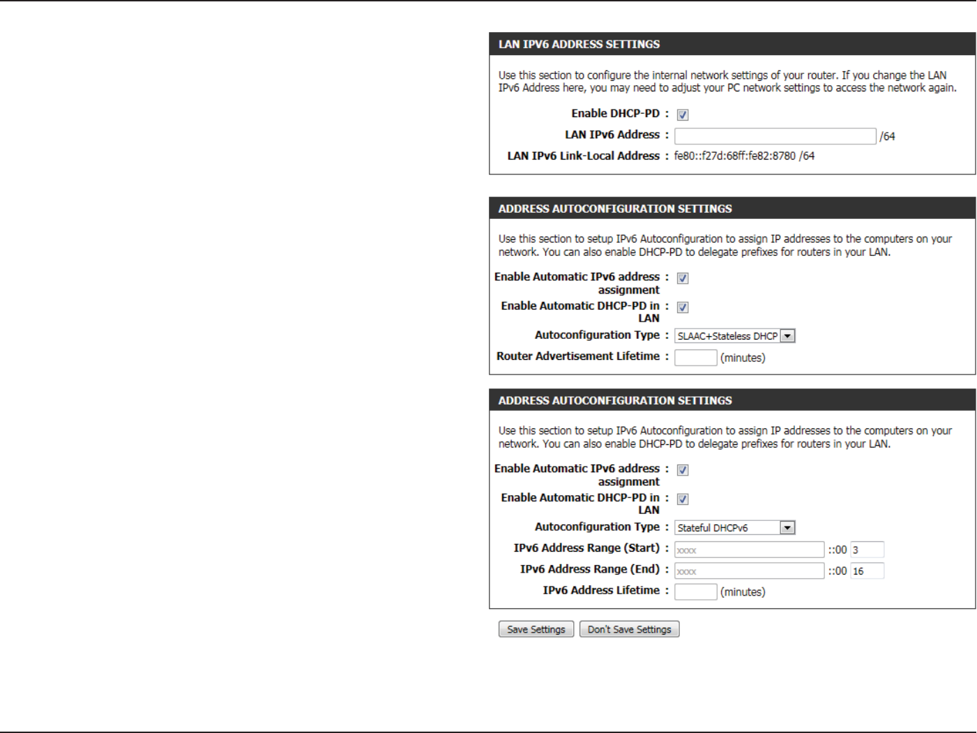
The following parameters will be available for conguration:
Enable DHCP-
PD:
Select this option to enable DHCP PD.
LAN IPv6
Address:
Enter the LAN IPv6 address used here. This address
must be in the ‘/64’ subnet.
LAN IPv6 Link-
Local Address:
Displays the LAN IPv6 Link-Local address used
here.
The following parameters will be available for conguration:
Enable Automatic
IPv6 address:
The user can tick this option to enable the auto-
conguration feature.
Enable Automatic
DHCP-PD in LAN:
Tick this option to enable the automatic DHCP-
PD on the LAN.
Autoconguration
Type:
The user can select the auto-conguration type
used here.
Router
Advertisement
Lifetime:
This option is only available when the auto-
conguration type is set to Stateless. Enter the
router advertisement lifetime value used here.
IPv6 Address
Range (Start):
This option is only available when the auto-
conguration type is set to Stateful. Enter the
start IPv6 Address for the DHCPv6 range for your
local computers.
IPv6 Address
Range (End):
This option is only available when the auto-
conguration type is set to Stateful. Enter the
end IPv6 Address for the DHCPv6 range for your
local computers.
IPv6 Address
Lifetime:
This option is only available when the auto-
conguration type is set to Stateful. Enter the
IPv6 Address Lifetime (in minutes).
Click on the Save Settings button to accept the changes made.
Click on the Don’t Save Settings button to discard the changes made.
Section 3 - Software Conguration
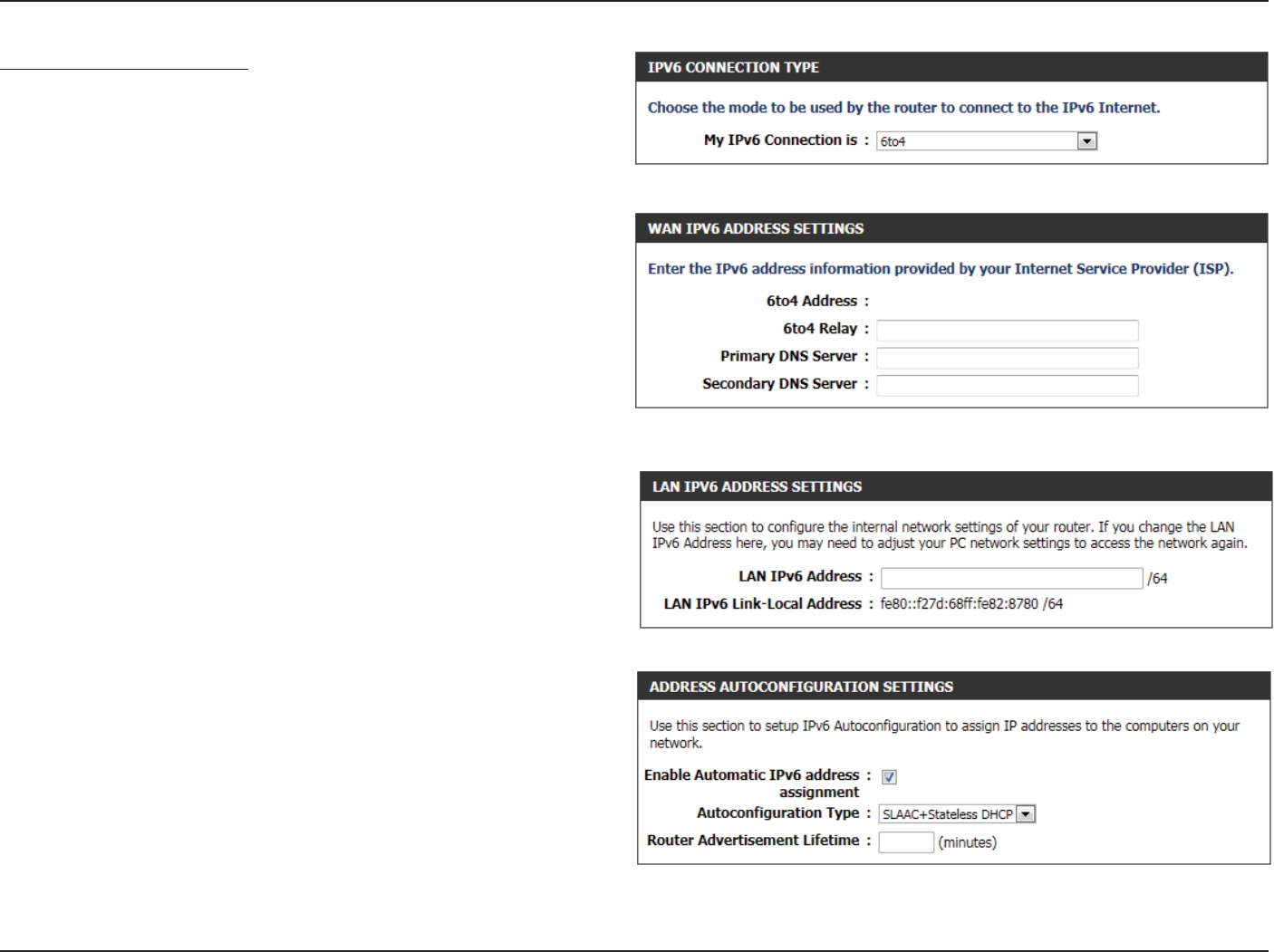
IPv6 Connection Type: 6to4
In this section the user can congure the IPv6 6to4 connection settings.
6to4 is an IPv6 address assignment and automatic tunneling technology
that used to provide unicast IPv6 connectivity between IPv6 sites and
hosts across the IPv4 Internet.
The following parameters will be available for conguration:
6to4 Address: Here the 6to4 congured address will be displayed.
6to4 Relay: Enter the 6to4 relay address used here.
Primary DNS
Server:
Enter the primary DNS Server address used here.
Secondary DNS
Server:
Enter the secondary DNS Server address used
here.
The following parameters will be available for conguration:
LAN IPv6
Address:
Enter the LAN IPv6 address used here. This address
must be in the ‘/64’ subnet.
LAN IPv6 Link-
Local Address:
Displays the LAN IPv6 Link-Local address used
here.
Enable Automatic
IPv6 address
Autoconguration
Type:
Router
Advertisement
Lifetime:
The user can tick this option to enable the auto-
conguration feature.
The user can select the auto-conguration type
used here.
This option is only available when the auto-
conguration type is set to Stateless. Enter the
router advertisement lifetime value used here
Section 3 - Software Conguration
The following parameters will be available for conguration:
Enable Automatic
IPv6 address:
The user can tick this option to enable the auto-
conguration feature.
Autoconguration
Type:
The user can select the auto-conguration type
used here.
IPv6 Address
Range (Start):
This option is only available when the auto-
conguration type is set to Stateful. Enter the
start IPv6 Address for the DHCPv6 range for your
local computers.
IPv6 Address
Range (End):
This option is only available when the auto-
conguration type is set to Stateful. Enter the
end IPv6 Address for the DHCPv6 range for your
local computers.
IPv6 Address
Lifetime:
This option is only available when the auto-
conguration type is set to Stateful. Enter the
IPv6 Address Lifetime (in minutes).
Click on the Save Settings button to accept the changes made.
Click on the Don’t Save Settings button to discard the changes made.
Section 3 - Software Conguration
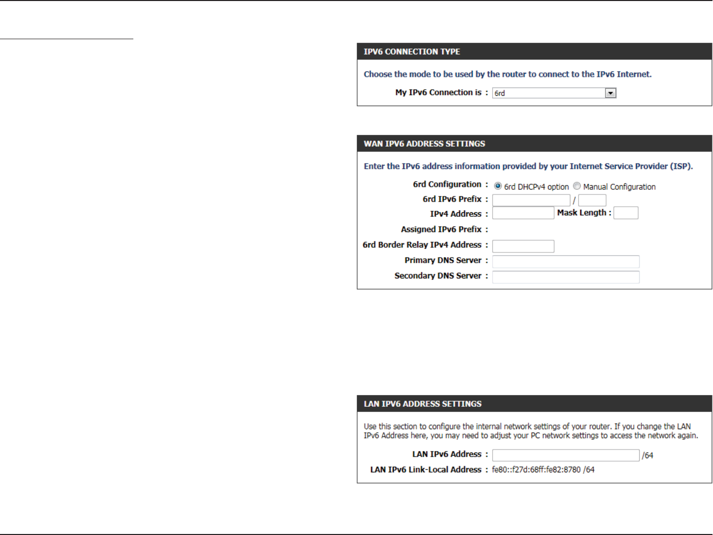
IPv6 Connection Type: 6rd
In this section the user can congure the IPv6 6rd connection settings.
The following parameters will be available for conguration:
6rd
Conguration:
Select the desired 6rd conguration option here.
6rd IPv6 Prex: Enter the 6rd IPv6 address and prex value used
here.
IPv4 Address: Enter the IPv4 address used here.
Mask Length: Enter the IPv4 mask length used here.
Assigned IPv6
Prex:
Displays the IPv6 assigned prex value here.
6rd Border Relay
IPv4 Address:
Enter the 6rd border relay IPv4 address used here.
Primary DNS
Server
Enter the primary DNS Server address used here.
Secondary DNS
Server:
Enter the secondary DNS Server address uses here.
The following parameters will be available for conguration:
LAN IPv6
Address:
Enter the LAN IPv6 address used here. This address
must be in the ‘/64’ subnet.
LAN IPv6 Link-
Local Address:
Displays the LAN IPv6 Link-Local address used
here.
Section 3 - Software Conguration
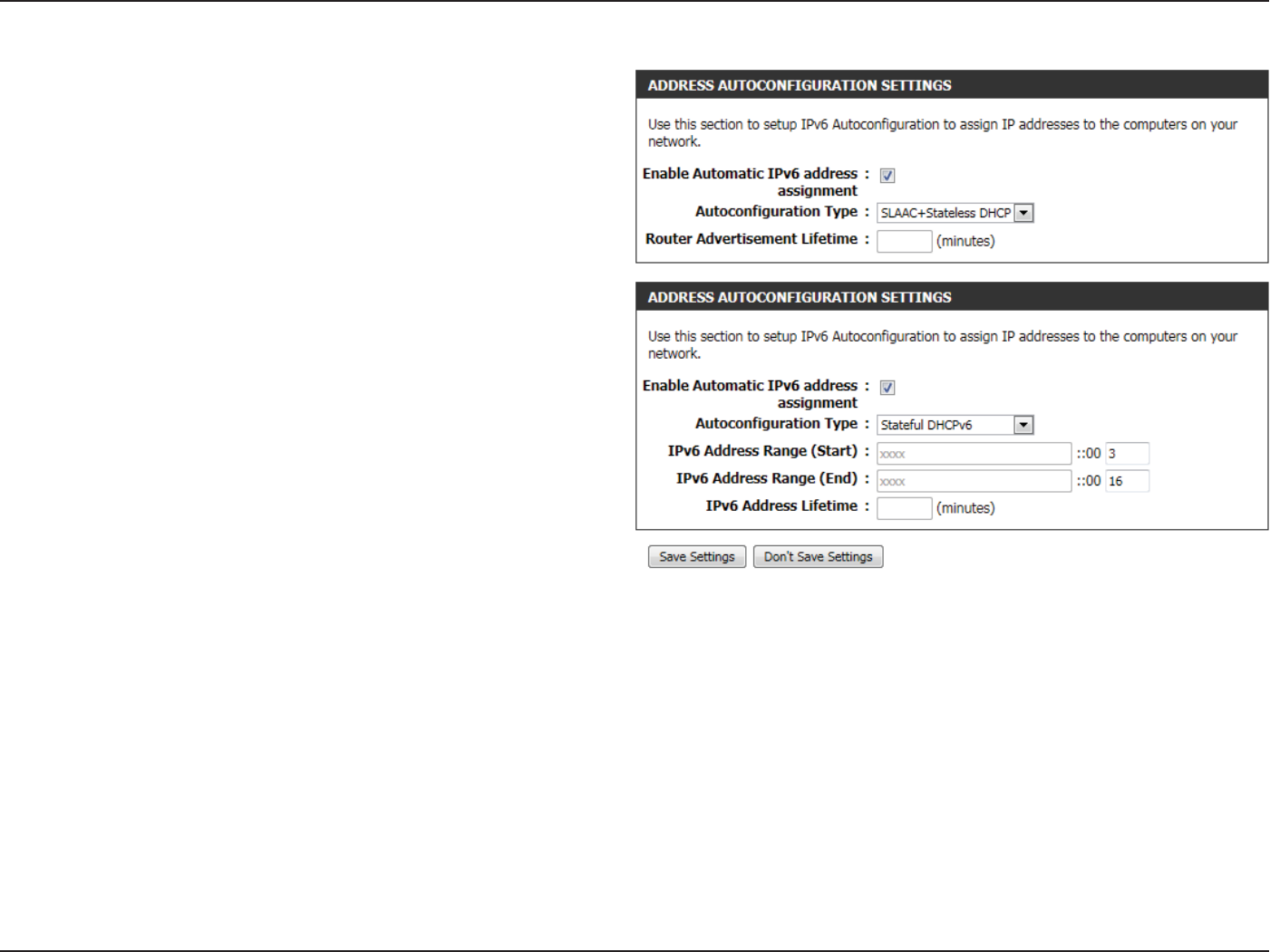
The following parameters will be available for conguration:
Enable Automatic
IPv6 address:
The user can tick this option to enable the auto-
conguration feature.
Autoconguration
Type:
The user can select the auto-conguration type
used here.
Router
Advertisement
Lifetime:
This option is only available when the auto-
conguration type is set to Stateless. Enter the
router advertisement lifetime value used here.
IPv6 Address
Range (Start):
This option is only available when the auto-
conguration type is set to Stateful. Enter the
start IPv6 Address for the DHCPv6 range for
your local computers.
IPv6 Address
Range (End):
This option is only available when the auto-
conguration type is set to Stateful. Enter the
end IPv6 Address for the DHCPv6 range for your
local computers.
IPv6 Address
Lifetime:
This option is only available when the auto-
conguration type is set to Stateful. Enter the
IPv6 Address Lifetime (in minutes).
Click on the Save Settings button to accept the changes made.
Click on the Don’t Save Settings button to discard the changes made.
Section 3 - Software Conguration
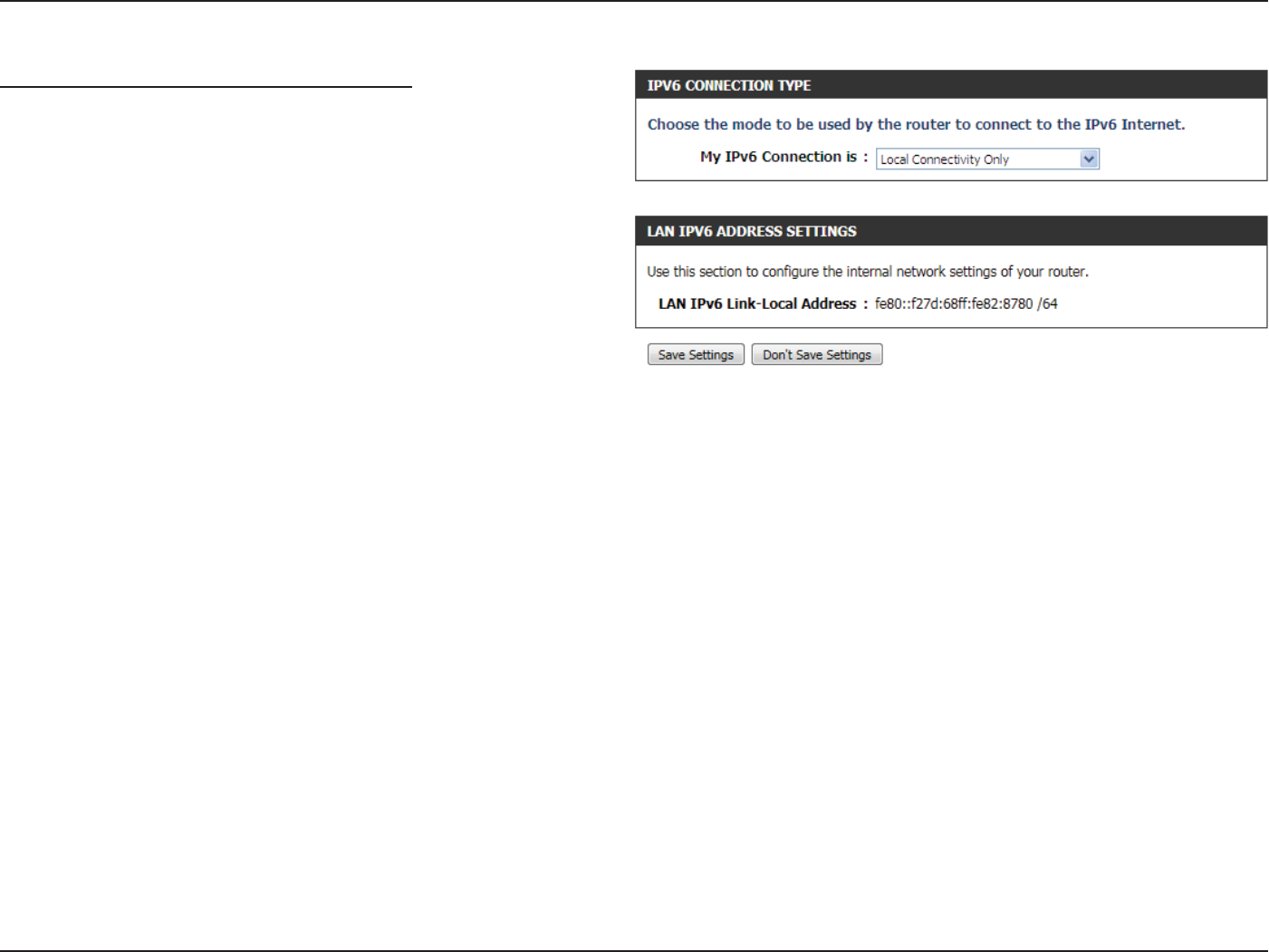
IPv6 Connection Type: Local Connection Only
The Link-local address is used by nodes and routers when communicating
with neighboring nodes on the same link. This mode enables IPv6-
capable devices to communicate with each other on the LAN side.
The following parameters will be available for conguration:
LAN IPv6 Link-
Local Address:
Displays the LAN IPv6 Link-Local address used
here.
Click on the Save Settings button to accept the changes made.
Click on the Don’t Save Settings button to discard the changes made.

Section 3 - Software Conguration
Advanced Category
This section allows the user to congure the more advanced features that can be done by this router. Features like Port Forwarding, Firewall
settings, Quality of Service settings and more.
Section 3 - Software Conguration
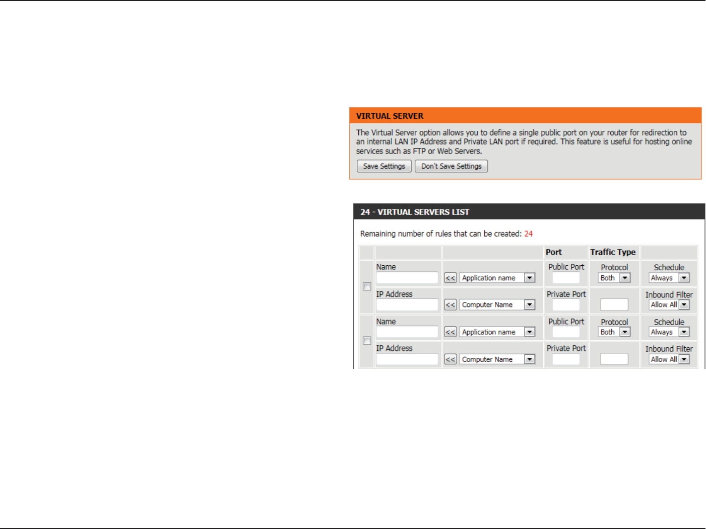
Virtual Server
This router can be congured as a virtual server so that remote users accessing Web or FTP services via the public IP address can be automatically
redirected to local servers in the LAN (Local Area Network). The router’s rewall feature lters out unrecognized packets to protect the LAN network
so all computers networked with the router are invisible to the outside world. The user can make some of the LAN computers accessible from the
Internet by enabling Virtual Server.
Depending on the requested service, the router redirects the external
service request to the appropriate server within the LAN network. The
router is also capable of port-redirection, meaning that incoming trac
to a particular port may be redirected to a dierent port on the server
computer.
Checkbox: Check the box on the left side to enable the Virtual
Server rule.
Name: Enter a name for the rule or select an application
from the drop-down menu. Select an application
and click << to populate the elds.
IP Address: Enter the IP address of the computer on your local
network that you want to allow the incoming
service to. If your computer is receiving an IP
address automatically from the router (DHCP),
you computer will be listed in the Computer Name
drop-down menu. Select your computer and click
<<.

Section 3 - Software Conguration
Port: Enter the port that you want to open next to Public Port and Private Port. The public and private ports are usually the same.
The public port is the port seen from the Internet side, and the private port is the port being used by the application on the
computer within your local network.
Trac Type: Select TCP, UDP, or All from the Protocol drop-down menu.
Schedule: Use the drop-down menu to schedule the time that the Virtual Server Rule will be enabled. The schedule may be set to
Always, which will allow the particular service to always be enabled. You can create your own times in the Schedules page.
Click on the Save Settings button to accept the changes made.
Click on the Don’t Save Settings button to discard the changes made.
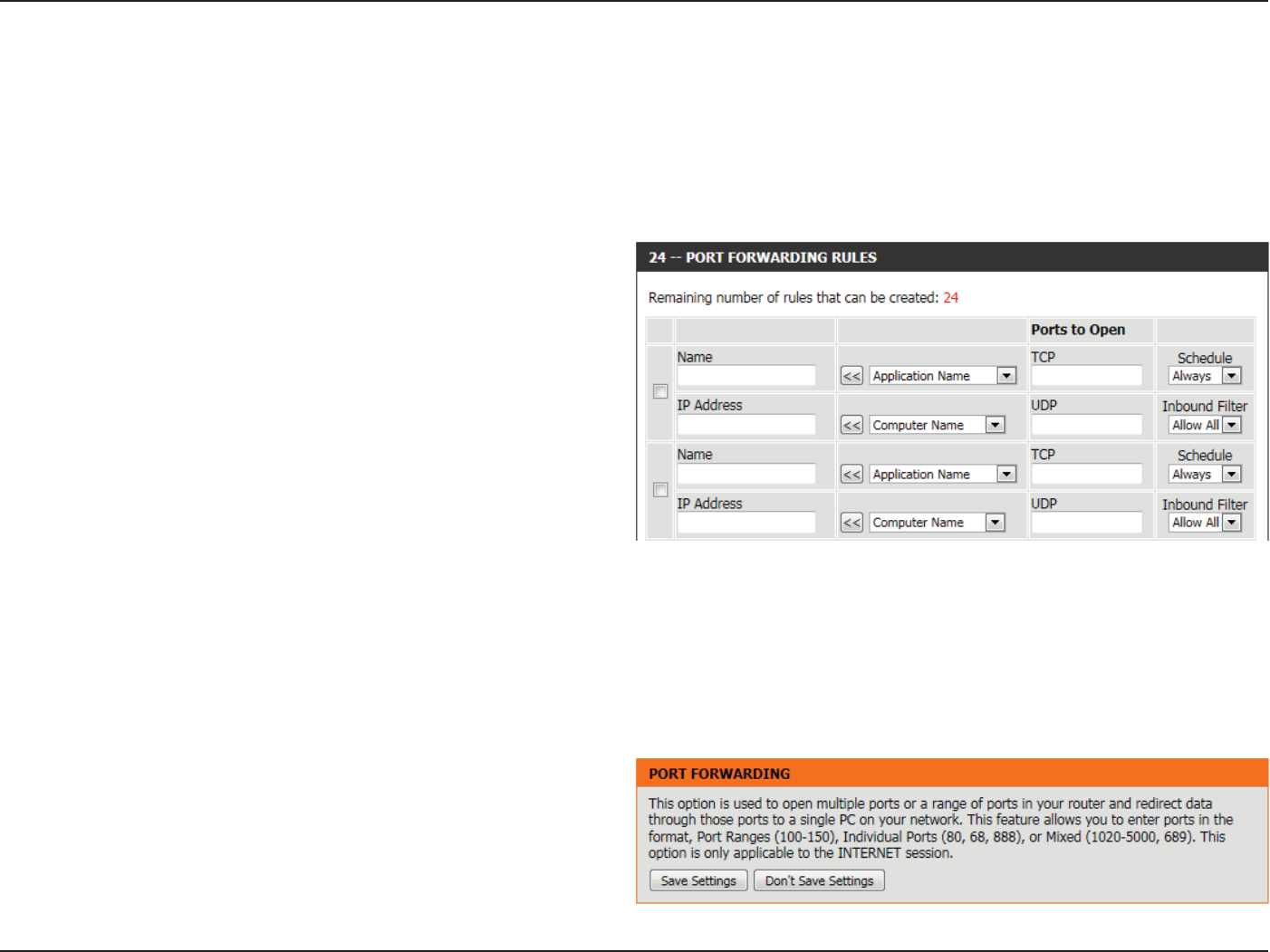
Section 3 - Software Conguration
Port Forwarding
The Port Forwarding option gives Internet users access to services on your LAN. This feature is useful for hosting online services such as FTP, Web or
game servers. For each entry, you dene a public port on your router for redirection to an internal LAN IP Address and LAN port. This option is used
to open multiple ports or a range of ports in your router and redirect data through those ports to a single PC on your network. This feature allows
you to enter ports in the format, Port Ranges (100-150), Individual Ports (80, 68, 888), or Mixed (1020-5000, 689). This option is only applicable to
the INTERNET session.
The following parameters will be available for conguration:
Checkbox: Tick the checkbox on the left side to enable the
Port Forwarding rule.
Name: Enter a name for the rule or select an application
from the drop-down menu. Select an application
and click << to populate the elds.
IP Address: Enter the IP address of the computer on your local
network that you want to allow the incoming
service to. If your computer is receiving an IP
address automatically from the router (DHCP),
you computer will be listed in the Computer Name
drop-down menu. Select your computer and click
<<.
Ports to Open: Enter the external port number in the appropriate space provided. If the port number is TCP then enter the number in the TCP
space, and if the port number is UDP than enter it in the UDP space.
Schedule: Use the drop-down menu to schedule the time that the Port Forwarding rule will be enabled. The schedule may be set to
Always, which will allow the particular service to always be enabled. You can create your own times in the Schedules page.
Inbound Filter: Select the inbound lter rule here. Options to choose from are Allow All, Deny All, and any other custom rule created.
Click on the Save Settings button to accept the changes made.
Click on the Don’t Save Settings button to discard the changes made.
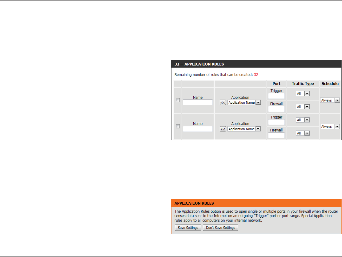
Section 3 - Software Conguration
Application Rules
Some applications require multiple connections, such as Internet gaming, video conferencing, Internet telephony and others. These applications
have diculties working through NAT (Network Address Translation). Special Applications makes some of these applications work with the router.
If you need to run applications that require multiple connections, specify the port normally associated with an application in the “Trigger Port”
eld, select the protocol type as TCP or UDP, then enter the rewall (public) ports associated with the trigger port to open them for inbound trac.
The following parameters will be available for conguration:
Checkbox: Check the box on the left side to enable the
Application Rule.
Name: Enter a name for the rule. You may select a
predened application from the Application
drop-down menu and click <<.
Application: Displays a list of predened application to use in
the rules.
Port (Trigger): This is the port used to trigger the application. It
can be either a single port or a range of ports.
Port (Firewall): This is the port number on the Internet side that
will be used to access the application. You may
dene a single port or a range of ports. You can
use a comma to add multiple ports or port ranges.
Trac Type: Select the protocol of the rewall port (TCP, UDP, or All).
Schedule: The schedule of time when the Application Rule will be enabled. The schedule may be set to Always, which will allow the
particular service to always be enabled. You can create your own times in the Schedules page.
Click on the Save Settings button to accept the changes made.
Click on the Don’t Save Settings button to discard the changes made.
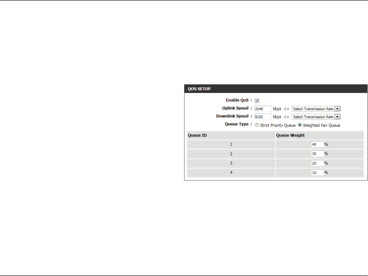
Section 3 - Software Conguration
QoS Engine
The QoS Engine option helps improve your network gaming performance by prioritizing applications. By default the QoS Engine settings are
disabled and application priority is not classied automatically. The QoS section contains a queuing mechanism, trac shaping and classication.
It supports two kinds of queuing mechanisms. Strict Priority Queue (SPQ) and Weighted Fair Queue (WFQ). SPQ will process trac based on
trac priority. Queue1 has the highest priority and Queue4 has the lowest priority. WFQ will process trac based on the queue weight. Users can
congure each queue’s weight. The sum of all the queue’s weight must be 100. When surng the Internet, the system will do trac shaping based
on the uplink and downlink speed. The classication rules can be used to classify trac to dierent queues, then SPQ or WFQ will do QoS based on
the queue’s priority or weight.
Enable QoS: This option is disabled by default. Enable this
option for better performance and experience with
online games and other interactive applications,
such as VoIP.
Uplink Speed: The speed at which data can be transferred from
the router to your ISP. This is determined by your
ISP. ISP’s often dene speed as a download/upload
pair. For example, 1.5Mbits/284Kbits. Using this
example, you would enter 284. Alternatively you
can test your uplink speed with a service such as
www.dslreports.com.
Downlink Speed: The speed at which data can be transferred from
the ISP to the router. This is determined by your
ISP. ISP’s often dene speed as a download/upload
pair. For example, 1.5Mbits/284Kbits.
Using this example, you would enter 1500. Alternatively you can test your downlink speed with a service such as www.
dslreports.com.
Queue Type: Here the user can specify the queue type used. When choosing the option Strict Priority Queue, the router will apply QoS
based on the internal specication for the queue ID’s listed. When choosing the option Weight Fair Queue, the router will
apply QoS based on the user dened percentage in the Queue Weight column.
Queue ID: In this column the Queue ID used will be displayed.
Queue Priority: In this column the Queue Priority used will be displayed.
Queue Weight: After choosing to use the Weight Fair Queue option, under Queue Type, the user will be able to manual enter the Queue
Weight for each individual Queue ID.
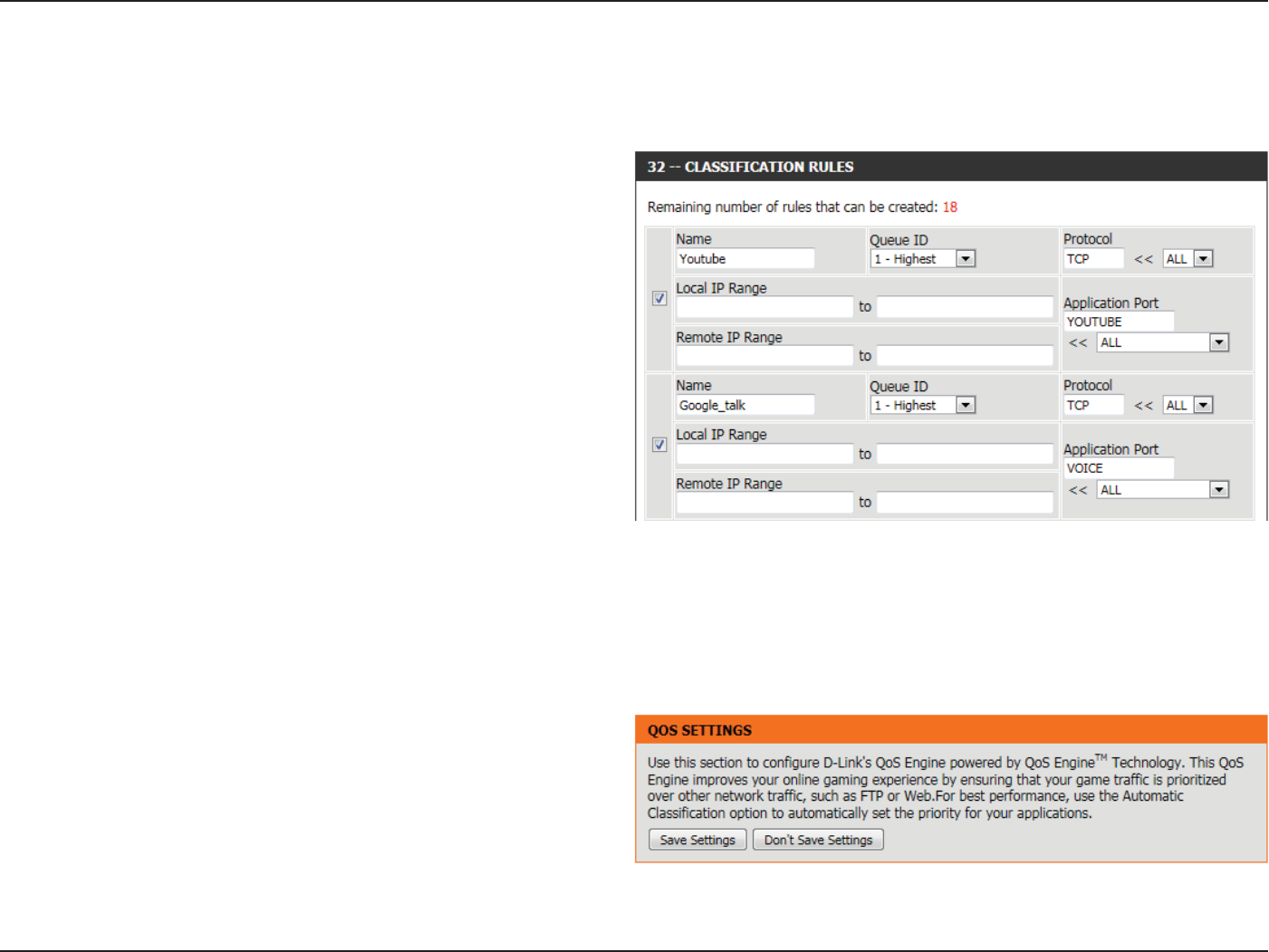
Section 3 - Software Conguration
The following parameters will be available for conguration:
Checkbox: Tick this option to enable the rule specied.
Name: Enter a custom name for the rule being created
here. This name is used for identication.
Queue ID: Select the appropriate priority requirement from
the drop-down menu that will be applied to this
rule. Option to choose from are Highest, Higher,
Normal, and Best Eort.
Protocol: Select the protocol used for the application for
in the drop-down menu and it will automatically
place it in the Protocol eld.
Local IP Range: Enter the local IP range used here. This is the IP
range of you Local Area Network. The Router’s IP
cannot be included in this range.
Remote IP
Range:
Enter the remote IP range used here. This is the
IP range of the public network from the Internet
Port side. To apply this rule to any IP addresses
from the public side, enter the range 0.0.0.1 to
255.255.255.254.
Application Port: Enter the application port number used here.
Click on the Save Settings button to accept the changes made.
Click on the Don’t Save Settings button to discard the changes made.
After specifying the QoS framework used, in the QoS setup section, the user can now create individual rules for scenarios that require the use of
trac control and data priority manipulation.
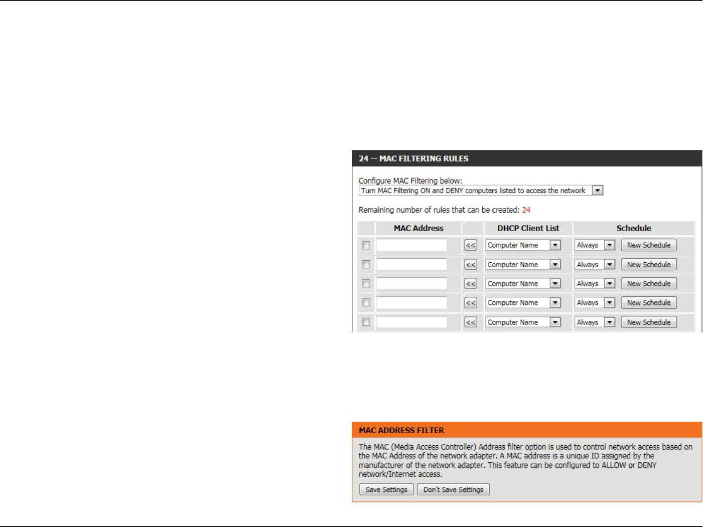
Section 3 - Software Conguration
Network Filter
The MAC (Media Access Controller) Address lter option is used to control network access based on the MAC Address of the network adapter. A
MAC address is a unique ID assigned by the manufacturer of the network adapter. This feature can be congured to ALLOW or DENY network/
Internet access.
In the MAC Filtering Rules section, the user can create and edit Network lter rules. This maximum amount of rules that can be created are 24 rules.
The following parameters will be available for conguration:
Congure MAC
Filtering below:
Select Turn MAC Filtering OFF, Turn MAC Filtering
ON and ALLOW computers listed to access the
network, or Turn MAC Filtering ON and DENY
computers listed to access the network from the
drop-down menu.
Checkbox: Check the box on the left side to enable the
Network Filter.
MAC Address: Enter the MAC address you would like to use in
this ltering rule.
DHCP Client List: Select a DHCP client from the Computer Name
drop-down menu and click << to copy that MAC
Address.
Schedule: The schedule of time when the Network Filter will
be enabled. The schedule may be set to Always,
which will allow the particular service to always be
enabled. Click the New Schedule button to create
your own times in the Schedules page.
Click on the Save Settings button to accept the changes made.
Click on the Don’t Save Settings button to discard the changes made.
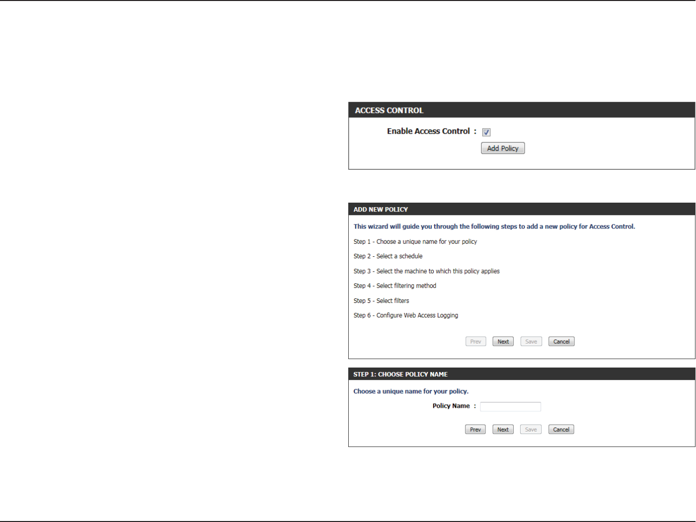
Section 3 - Software Conguration
Access Control
The Access Control option allows you to control access in and out of your network. Use this feature as Access Controls to only grant access to
approved sites, limit web access based on time or dates, and/or block internet access for applications like P2P utilities or games.
The following parameters will be available for conguration:
Enable Access
Control:
Tick this option to enable the Access Control
feature.
Add Policy: Click on this button to add a new Access Control
Policy.
After clicking on the Add Policy button, the add policy wizard will guide
you through the step-by-step process in adding a new policy. The rst
window explains the process.
Throughout this wizard the user will be able to:
Click on the Prev button to return to the previous window.
Click on the Next button to continue to the next window.
Click on the Cancel button to discard the changes made and return to
the main Access Control window.
Step 1: In the rst step, the user can enter the policy name used.
The following parameters will be available for conguration:
Policy Name: Enter the new policy name used for this rule here.
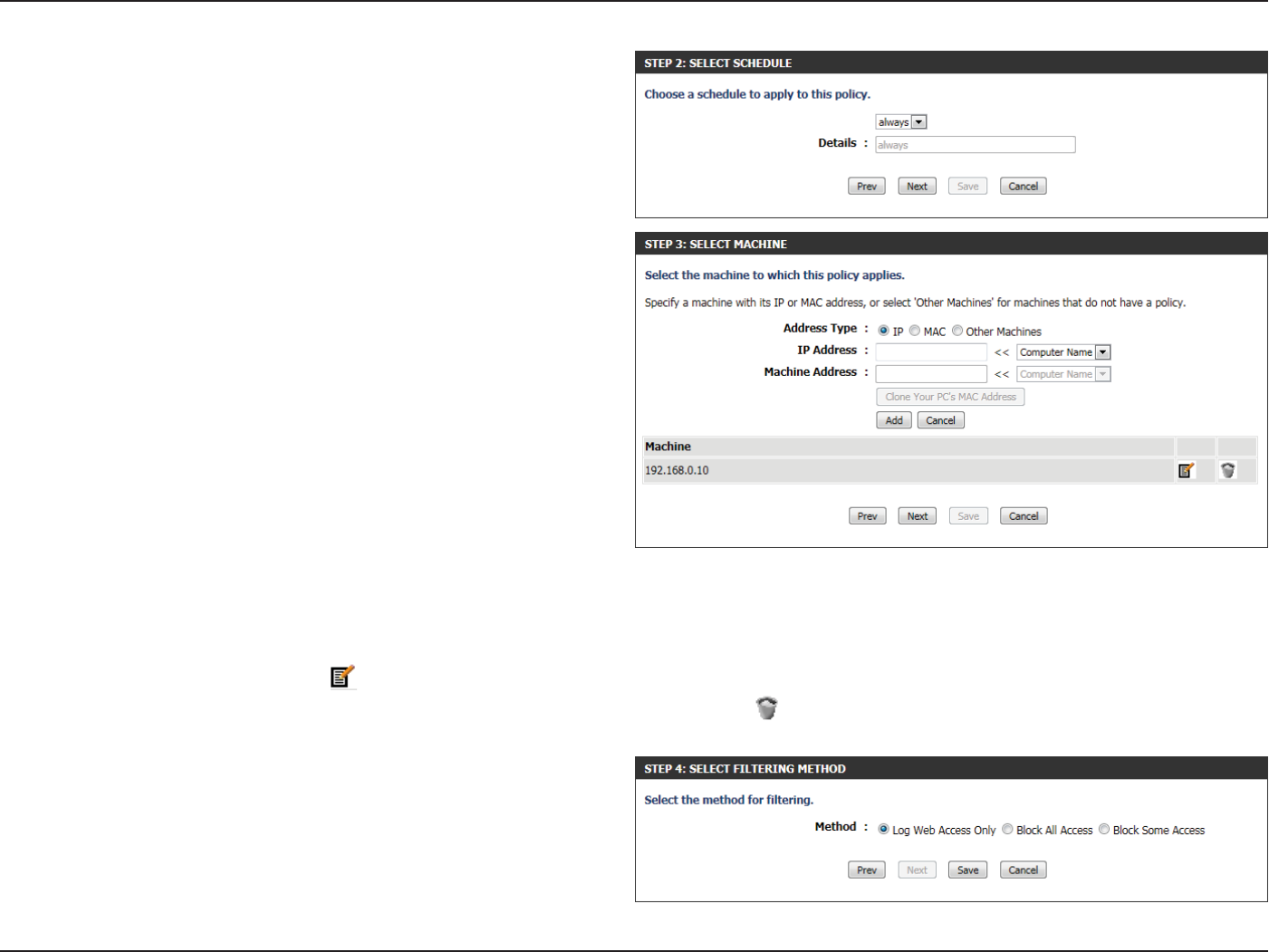
Section 3 - Software Conguration
Step 2: In the second step, the user can congure the schedule settings
for this rule.
The following parameters will be available for conguration:
Details: Select the appropriate predened schedule rule
to apply to this rule from the drop-down menu.
Step 3: In the third step, the user can congure the address type and IP
address of the machines used in this rule.
The following parameters will be available for conguration:
Address Type: Specify a machine with its IP or MAC address, or
select ‘Other Machines’ for machines that do not
have a policy.
IP Address: After selecting the IP address type, the user can
enter the IP address of the machines used in
this rule here. Alternatively, the user can select a
Computer from the Computer Name list.
Machine
Address:
After selecting the MAC address type, the user
can enter the MAC address of the machine used in
this rule here. Alternatively, the used can select a
Computer from the Computer Name list.
Add: Click on this button to add the machine to the list.
Update: After clicking the option, the user will be able to update the machine information.
Delete: If the user chooses to remove a machine from the list, click on the icon.
Step 4: In the fourth step, the user can select the ltering method used
for this rule.
The following parameters will be available for conguration:
Method: Here the user can select the ltering method used.
Options to choose from are ‘Log Web Access Only’,
‘Block All Access’, and ‘Block Some Access’.
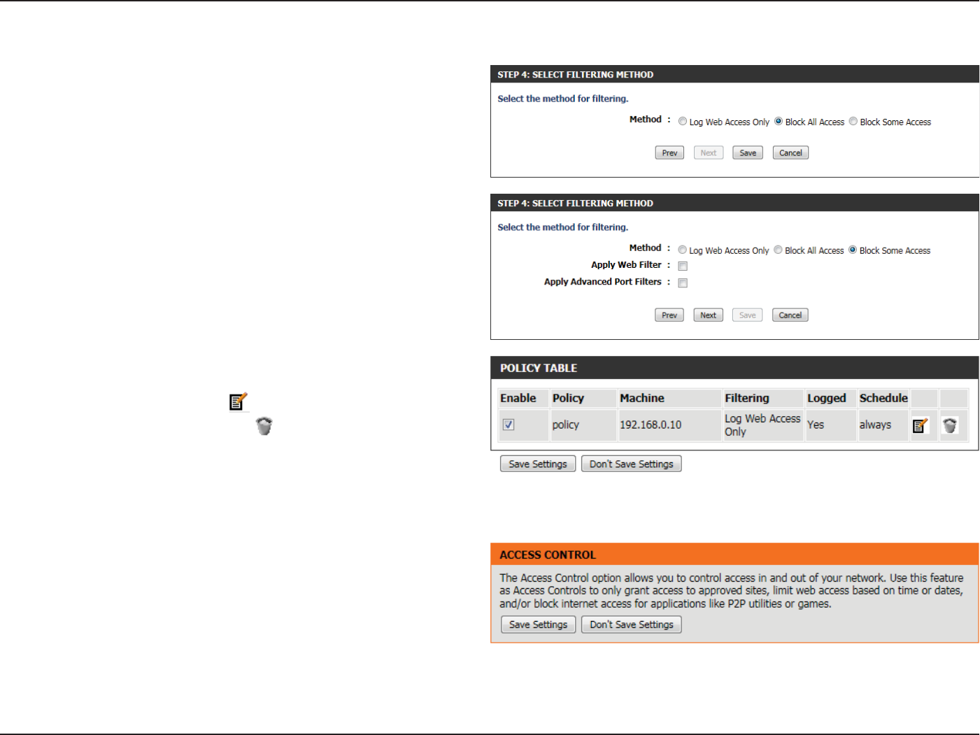
Section 3 - Software Conguration
The following parameters will be available for conguration:
Apply Web Filter: After selecting the ‘Block Some Access’ option,
the user will be able to select this option. Selecting
this option will allow the web lter access control
feature to be applied to this rule.
Apply Advanced
Port Filters:
After selecting the ‘Block Some Access’ option,
the user will be able to select this option. Selecting
this option will allow the advanced port lters
access control feature to be applied to this rule.
Click on the Save button to accept the changes made and return to the
main Access Control window.
In the Policy Table section a list on access control rules will be displayed.
To edit a specic rule, click on the icon.
To remove a specic rule, click on the icon.
Click on the Save Settings button to accept the changes made.
Click on the Don’t Save Settings button to discard the changes made.
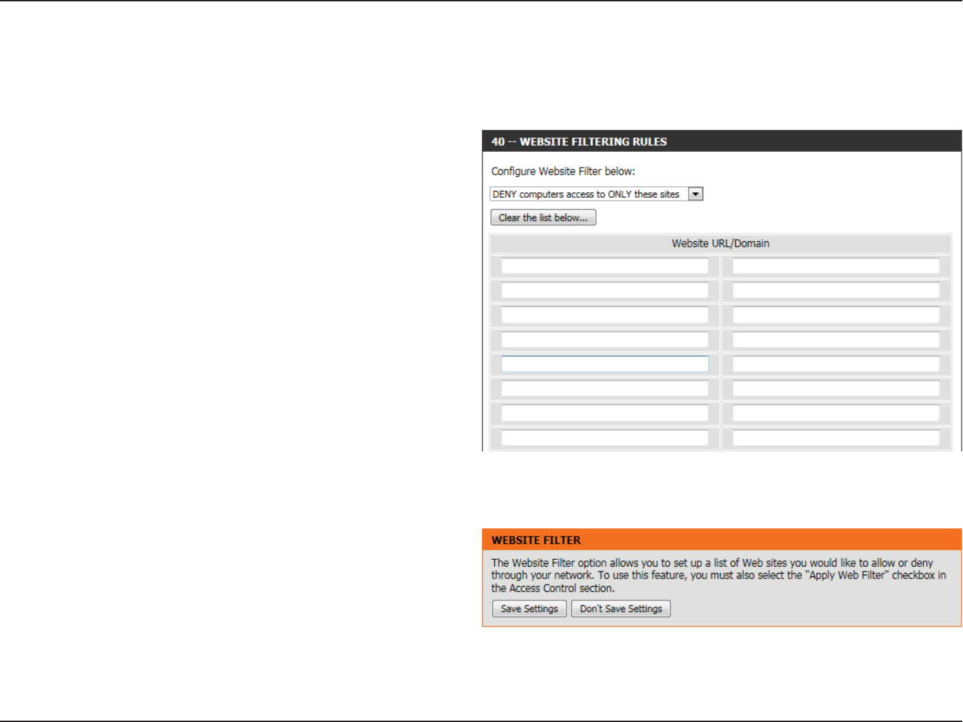
Section 3 - Software Conguration
Website Filter
Website Filters are used to allow you to set up a list of Web sites that can be viewed by multiple users through the network.
Website Filter is used to allow or deny computers on your network from
accessing specic web sites by keywords or specic Domain Names.
Select ‘ALLOW computers access to ONLY these sites’ in order only
allow computers on your network to access the specied URLs and
Domain Names. ‘DENY computers access to ONLY these sites’ in order
deny computers on your network to access the specied URLs and
Domain Names.
The following parameters will be available for conguration:
Website URL/
Domain:
Enter the URL or Domain name that you want to
allow or block here.
An example of an URL is: http://www.facebook.
com/
An example of a domain name is: facebook.com
Click on the Clear the list below... button to remove all the entries from
the spaces in the list.
Click on the Save Settings button to accept the changes made.
Click on the Don’t Save Settings button to discard the changes made.
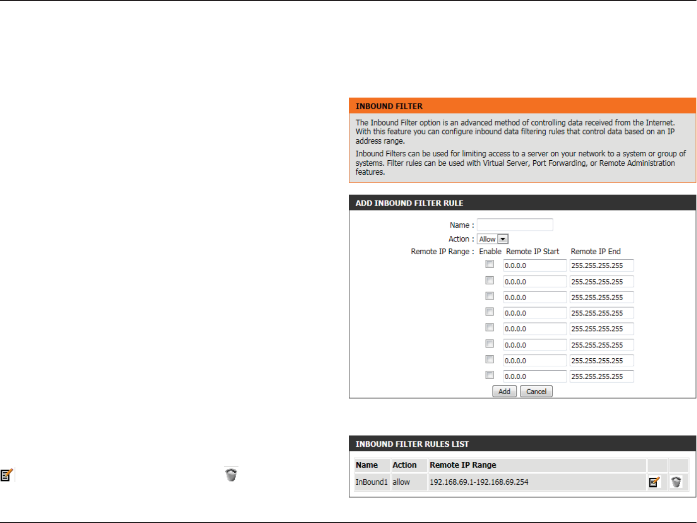
Section 3 - Software Conguration
Inbound Filter
The Inbound Filter option is an advanced method of controlling data received from the Internet. With this feature you can congure inbound
data ltering rules that control data based on an IP address range. Inbound Filters can be used for limiting access to a server on your network to a
system or group of systems. Filter rules can be used with Virtual Server, Port Forwarding, or Remote Administration features. The user can add new
Inbound lter rule in the next section.
The following parameters will be available for conguration:
Name: The user can enter a custom name for the inbound
lter rule here.
Action: Select an action that will take place when this rule
is initiated. Options to choose from are Allow and
Deny.
Enable: Tick this option to enable the specied IP range
for this rule.
Remote IP Start: Enter the remote starting IP address here in the
range.
Remote IP End: Enter the remote ending IP address here in the
range.
Add: Click this button to add the new inbound lter
rule.
Cancel: Click this button to discard the new inbound lter
rule.
In the Inbound Filter Rules List section, the user can view a list of the
inbound lter rules already created. To edit a specic rule, click on the
icon. The delete a specic rule, click on the icon.
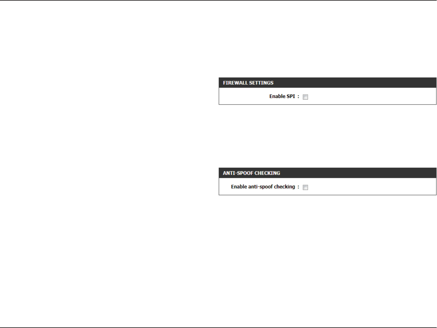
Section 3 - Software Conguration
Firewall Settings
A rewall protects your network from the outside world. The router oers a rewall type functionality. The SPI feature helps prevent cyber attacks.
Sometimes you may want a computer exposed to the outside world for certain types of applications. If you choose to expose a computer, you can
enable DMZ. DMZ is short for Demilitarized Zone. This option will expose the chosen computer completely to the outside world.
The following parameters will be available for conguration:
Enable SPI: Check the Enable SPI box to enable the SPI (Stateful
Packet Inspection, also known as dynamic packet
ltering) feature. Enabling SPI helps to prevent
cyber attacks by tracking more state per session.
It validates that the trac passing through the
session conforms to the protocol.
The following parameters will be available for conguration:
Enable anti-
spoof checking:
Tick this option to enable the anti-spoof checking
feature.
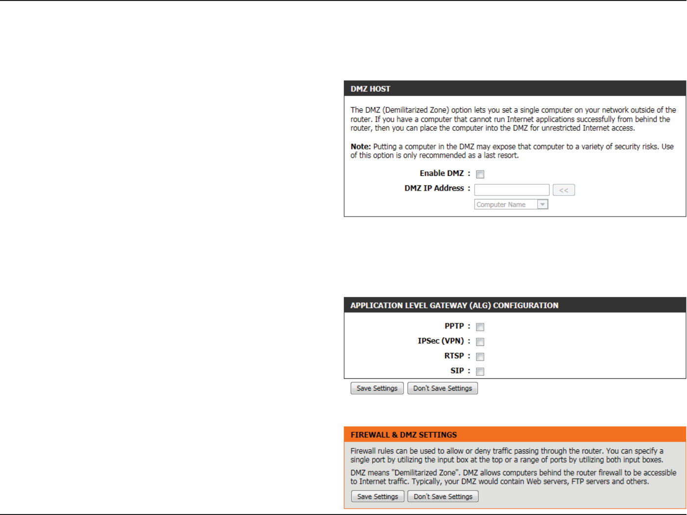
Section 3 - Software Conguration
The following parameters will be available for conguration:
Enable DMZ: Tick this option to enable the DMZ feature.
DMZ IP Address: Enter the IP address of the computer on the
LAN that you want to have unrestricted Internet
communication in the DMZ IP address eld. To
specify an existing DHCP client, use the Computer
Name drop-down to select the computer that you
want to make a DMZ host. If selecting a computer
that is a DHCP client, be sure to make a static
reservation in the Setup > Network Settings page
so that the IP address of the DMZ machine does
not change.
The following parameters will be available for conguration:
PPTP: Tick this option to allow PPTP access to the LAN
network.
IPSec (VPN): Tick this option to allow IPSec (VPN) access to the
LAN network.
RSTP: Tick this option to allow RSTP access to the LAN
network.
SIP: Tick this option to allow SIP access to the LAN
network.
Click on the Save Settings button to accept the changes made.
Click on the Don’t Save Settings button to discard the changes made.
Firewall rules can be used to allow or deny trac passing through the router. You can specify a single port by utilizing the input box at the top or
a range of ports by utilizing both input boxes. DMZ means “Demilitarized Zone”. DMZ allows computers behind the router rewall to be accessible
to Internet trac. Typically, your DMZ would contain Web servers, FTP servers and others.
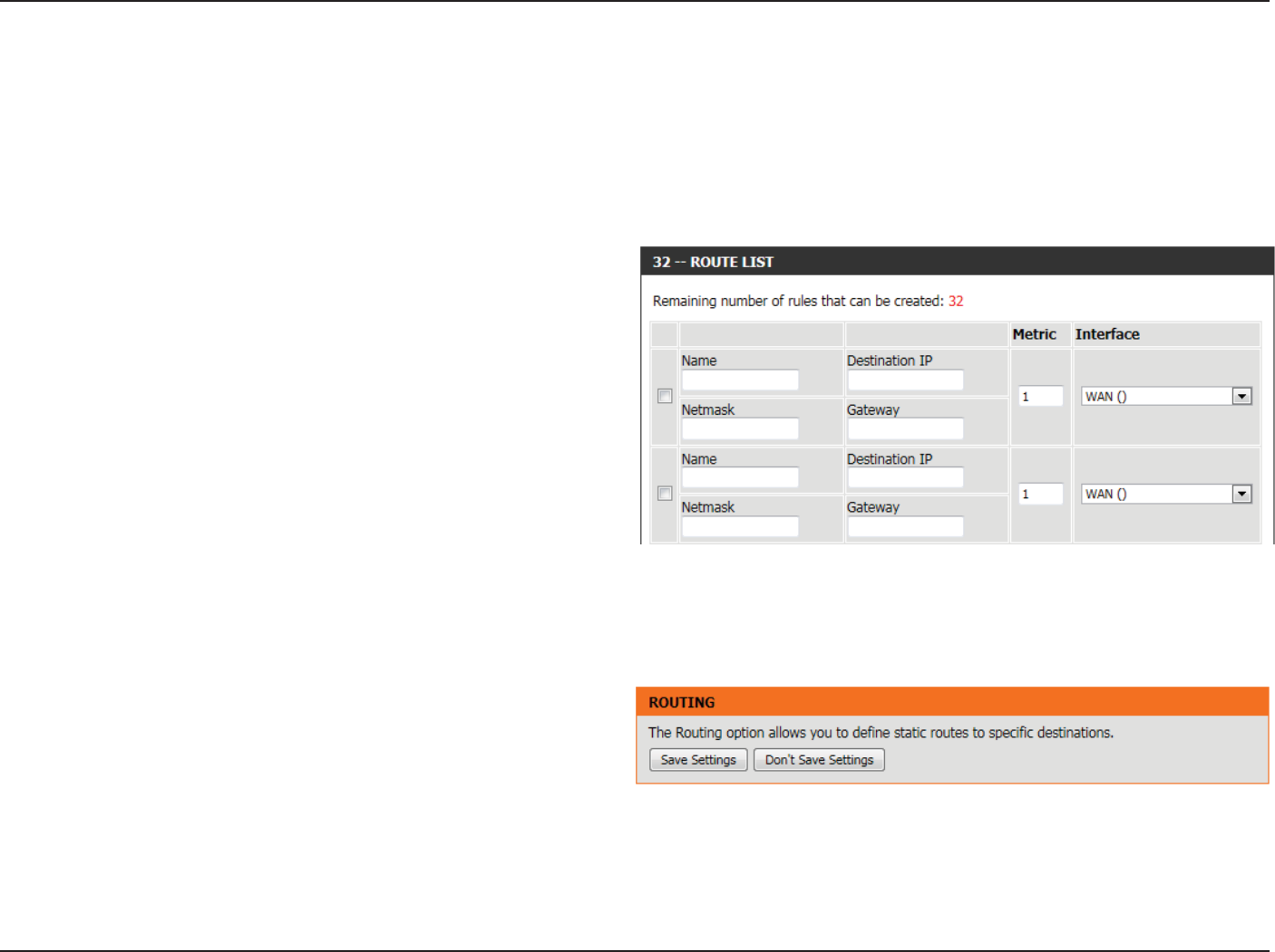
Section 3 - Software Conguration
Routing
The Routing option is an advanced method of customizing specic routes of data through your network.
In the Routing List section, the user can congure routing rules used by this router. The maximum amount of rules that can be congured is 32.
The following parameters will be available for conguration:
Checkbox: To enable a route, check the box that is on the left
side of the route.
Name: Enter a name for the rule used here.
Destination IP: Enter the IP address of the packets that will take
this route.
Netmask: Enter the netmask to specify the subnet of the IP
packets that will take this route.
Gateway: Enter the next hop that will be taken if this route
is used.
Metric: Enter the metric value that this route will use here.
Interface: Use the drop-down menu to specify if the IP packet must use the WAN or LAN interface to transit out of the Router.
Click on the Save Settings button to accept the changes made.
Click on the Don’t Save Settings button to discard the changes made.
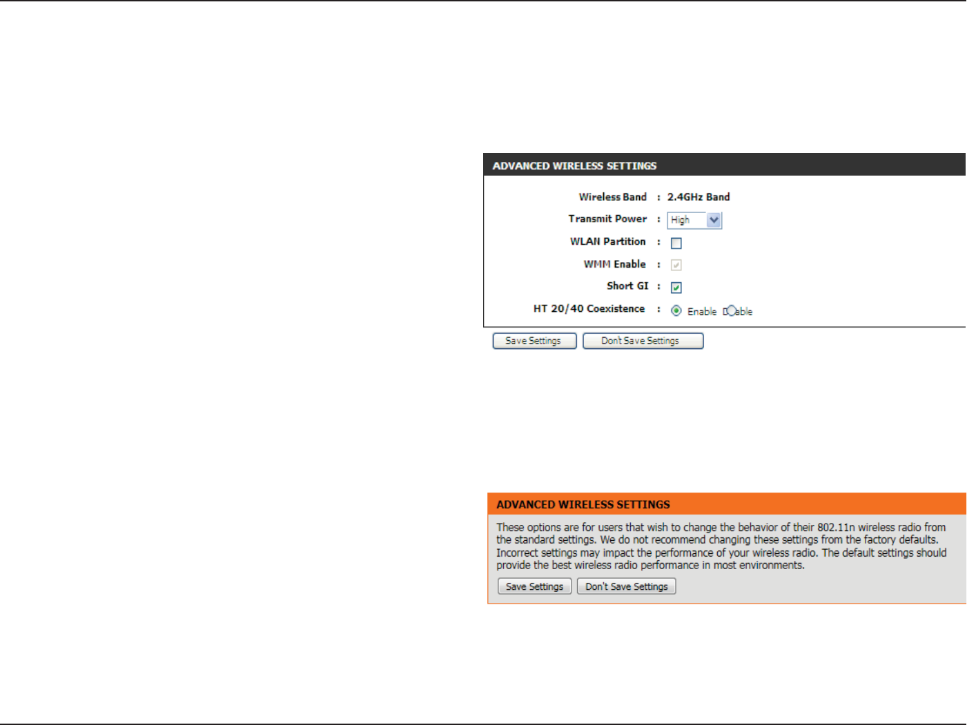
Section 3 - Software Conguration
Advanced Wireless
These options are for users that wish to change the behavior of their 802.11n wireless radio from the standard settings. We do not recommend
changing these settings from the factory defaults. Incorrect settings may impact the performance of your wireless radio. The default settings
should provide the best wireless radio performance in most environments.
The following parameters will be available for conguration:
Wireless Band: Here the user can view the wireless frequency
band being congured. In the case 2.4GHz.
Transmit Power: This option sets the transmit power of the
antennas.
WLAN Partition:
WMM Enable:
Short GI:
HT 20/40
Coexistence:
Check this box to enable WLAN Partition.
Check this box to enable the WMM feature.
Check this box to reduce the guard interval time
therefore increasing the data capacity.
However, it’s less reliable and may create higher
data loss.
Click on the Save Settings button to accept the changes made.
Click on the Don’t Save Settings button to discard the changes made.
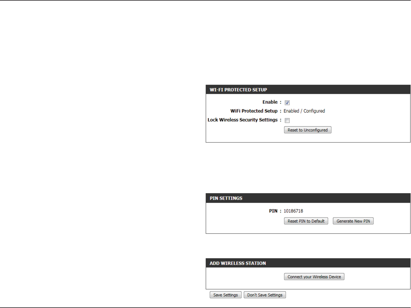
Section 3 - Software Conguration
Wi-Fi Protected Setup
Wi-Fi Protected Setup (WPS) System is a simplied method for securing your wireless network during the “Initial setup” as well as the “Add New
Device” processes. The Wi-Fi Alliance (WFA) has certied it across dierent products as well as manufactures. The process is just as easy, as depressing
a button for the Push-Button Method or correctly entering the 8-digit code for the Pin-Code Method. The time reduction in setup and ease of use
are quite benecial, while the highest wireless Security setting of WPA2 is automatically used.
The following parameters will be available for conguration:
Enable: Tick this option to enable the Wi-Fi Protected
Setup feature.
WiFi Protected
Setup:
This parameter displays the WPS setup status.
Lock Wireless
Security
Settings:
Tick this option to lock the congured wireless
security settings.
In the PIN Settings section, the user not only will be able to view the PIN code, but will also be able to reset the PIN to default or to generate a
new PIN code. A PIN is a unique number that can be used to add the router to an existing network or to create a new network. The default PIN
may be printed on the bottom of the router. For extra security, a new PIN can be generated. You can restore the default PIN at any time. Only the
Administrator (“admin” account) can change or reset the PIN.
In the Wi-Fi Protected Setup section, the user can enable the WPS feature of this router.
The following parameters will be available for conguration:
PIN: Shows the current value of the router’s PIN.
Reset PIN to
Default:
Click this button to restore the default PIN of the
router.
Generate New
PIN:
Click this button to create a random number that
is a valid PIN. This becomes the router’s PIN. You
can then copy this PIN to the user interface of the
registrar.
Click the ‘Connect your Wireless Device’ button to start Wireless
Connection Setup Wizard. This wizard helps you add wireless devices to
the wireless network.
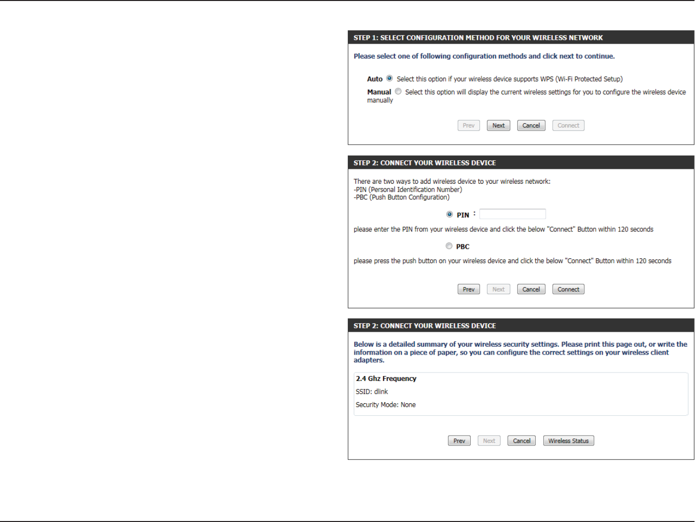
Section 3 - Software Conguration
Step 1: In this step the user have two options to choose from. You
can choose Auto if the wireless client supports WPS, or Manual if the
wireless client does not support WPS.
Click on the Prev button to return to the previous page. Click on the
Next button to continue to the next page. Click on the Cancel button to
discard the changes made and return to the main wireless page.
Step 2: After selecting Auto, the following page will appear. There are
two ways to add a wireless device, that supports WPS. Firstly, there is the
Personal Identication Number (PIN) method. Using this method will
prompt the user to enter a PIN code. This PIN code should be identical
on the wireless client. Secondly, there is the Push Button Conguration
(PBC) method. Using this method will allow the wireless client to
connect to this device by similarly pressing the PBC button on it.
Click on the Prev button to return to the previous page. Click on the
Next button to continue to the next page. Click on the Cancel button to
discard the changes made and return to the main wireless page.
Step 2: After selecting Manual, the following page will appear. On this
page to user can view the wireless conguration of this router. The
wireless clients should congure their wireless settings to be identical
to the settings displayed on this page for a successful connection. This
option is for wireless clients that can’t use the WPS method to connect
to this device.
Click on the Prev button to return to the previous page. Click on the
Next button to continue to the next page. Click on the Cancel button to
discard the changes made and return to the main wireless page. Click
on the Wireless Status button to navigate to the Status > Wireless page
to view what wireless client are connected to this device.
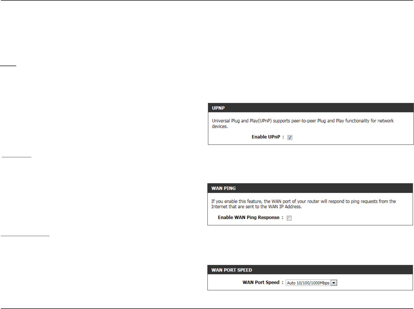
Section 3 - Software Conguration
Advanced Network
This section contains settings which can change the way the router handles certain types of trac. We recommend that you not change any of
these settings unless you are already familiar with them or have been instructed to change them by one of our support personnel.
The following parameters will be available for conguration:
Enable UPnP: Tick this option to enable the UPnP feature of the
router.
UPnP
UPnP is short for Universal Plug and Play which is a networking architecture that provides compatibility among networking equipment, software,
and peripherals. The device is a UPnP enabled router, meaning it will work with other UPnP devices/software. If you do not want to use the UPnP
functionality, it can be disabled by selecting “Disabled”.
WAN Ping
When you Enable WAN Ping response, you are causing the public WAN (Wide Area Network) IP address on the device to respond to ping commands
sent by Internet users. Pinging public WAN IP addresses is a common method used by hackers to test whether your WAN IP address is valid.
The following parameters will be available for conguration:
Enable WAN
Ping Response:
Tick this option to enable the WAN Ping Response
option of the router.
WAN Port Speed
This allows you to select the speed of the WAN interface of the router. Option to choose from are Auto 10/100/1000Mbps, 10Mbps, 100Mbps, or
1000Mbps.
The following parameters will be available for conguration:
WAN Port Speed: You may set the port speed of the Internet port
to Auto 10/100/1000Mbps, 10Mbps, 100Mbps,
or 1000Mbps. Some older cable or DSL modems
may require you to set the port speed to 10Mbps.
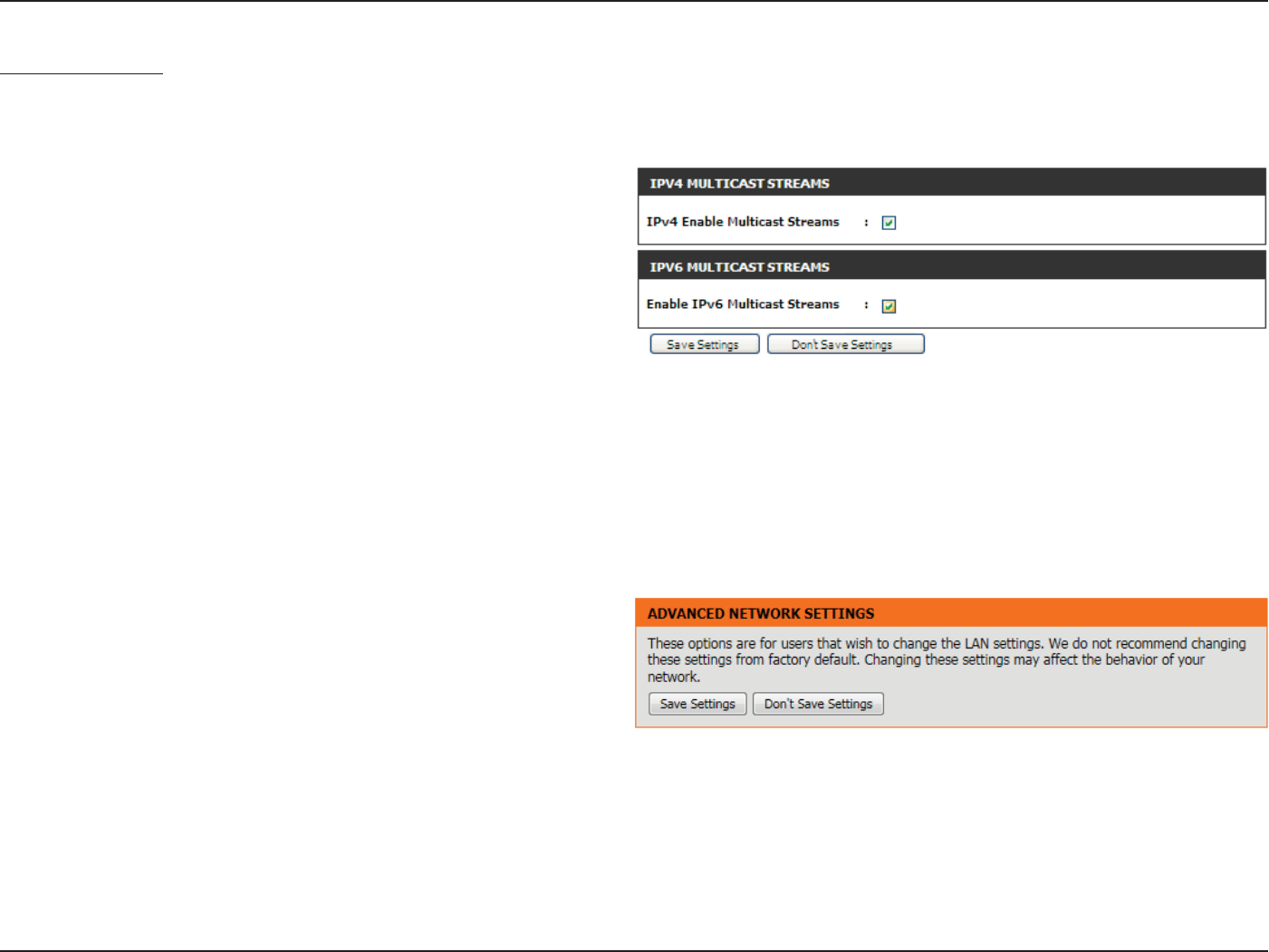
Section 3 - Software Conguration
Multicast Streams
This section enables the user to allow IPv4 or IPv6 Multicast trac to pass from the Internet to your network more eciently.
The following parameters will be available for conguration:
IPv4 Enable
Multicast
Streams
Enable IPv6
Multicast
Streams
Enable Multicast
Streams:
Enable this option if you are receiving video on
demand type of service from the Internet. The
router uses the IGMP protocol to support ecient
multicasting transmission of identical content,
such as multimedia, from a source to a number
of recipients. This option must be enabled if any
applications on the LAN participate in a multicast
group. If you have a multimedia LAN application
that is not receiving content as expected, try
enabling this option.
Click on the Save Settings button to accept the changes made.
Click on the Don’t Save Settings button to discard the changes made.

Section 3 - Software Conguration
Tools Category
In this category the user will be able to congure features that are related to the router itself. Features like the time settings, login accounts,
rmware update and more.
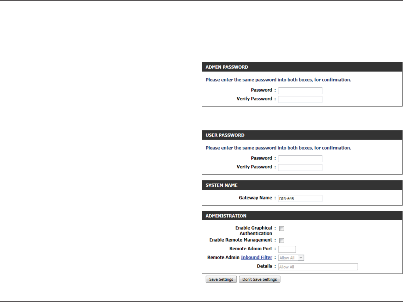
Section 3 - Software Conguration
Admin
In the Admin Password section, the user can change the Administrator
login password used for this device.
The following parameters will be available for conguration:
Password: Enter the new login password used here.
Verify Password: Re-enter the new login password here.
In the User Password section, the user can change the User login
password used for this device.
The following parameters will be available for conguration:
Password: Enter the new login password used here.
Verify Password: Re-enter the new login password here.
In the System Name section, the user can change the gateway name
used for this device.
The following parameters will be available for conguration:
Gateway Name: Enter the router gateway name used here.
The following parameters will be available for conguration:
Enable Graphical
Authentication:
Tick this option to enable the graphical image
conrmation when the user login to the web
conguration.
This page will allow you to change the Administrator password and congure the authentication settings. This window also allows you to enable
Remote Management, via the Internet. For security reasons, it is recommended that you change the password for the Admin and User accounts.
Be sure to write down the new password to avoid having to reset the router in case they are forgotten.
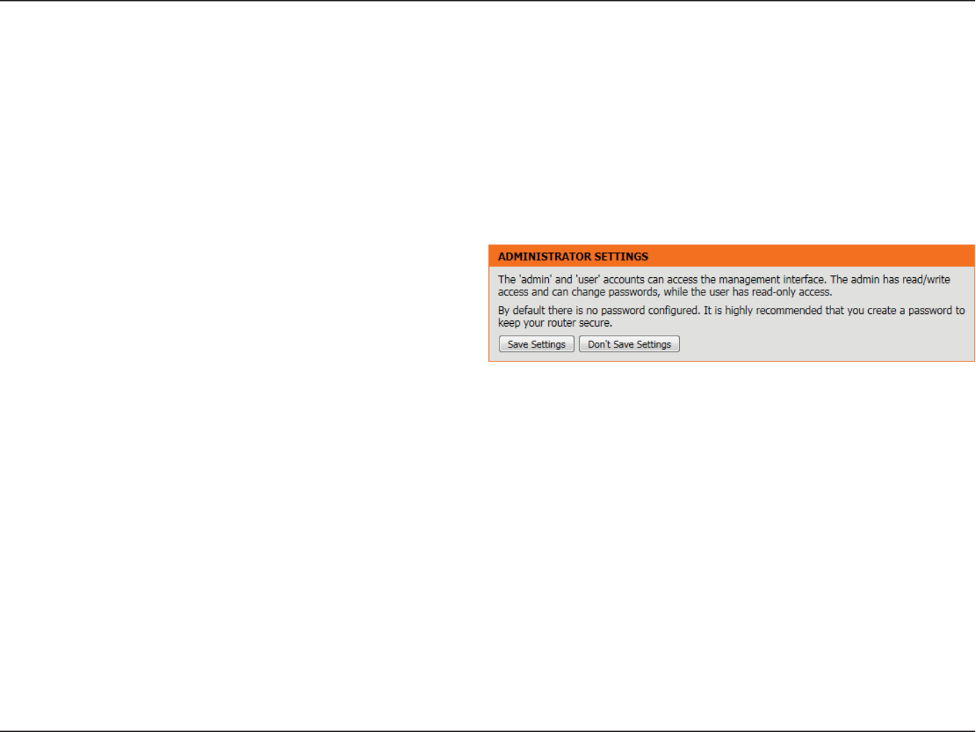
Section 3 - Software Conguration
Enable Remote
Management:
Tick this option to enable remote management.
This option will enable the router to be accessible
from the Internet port.
Remote Admin
Port:
Enter the remote administration port number used here. Sometimes services like an internal web server will occupy the port
number 80. In this option the user can change the remote administration port to 8080 for example.
Remote Admin
Inbound Filter:
Select the appropriate remote admin inbound lter behavior here. Options to choose from are Allow All and Deny All.
Details: Enter the remote admin inbound lter detail description used here.
Click on the Save Settings button to accept the changes made.
Click on the Don’t Save Settings button to discard the changes made.
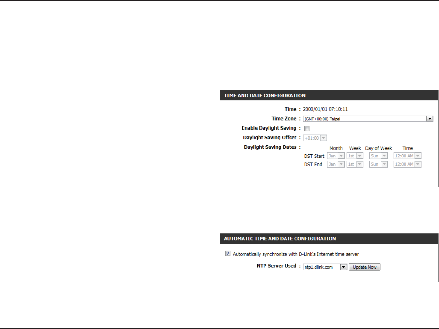
Section 3 - Software Conguration
Time
The Time window allows you to congure, update, and maintain the correct time on the internal system clock. From this section you can set the
time zone that you are in and set the Time Server. Daylight Saving can also be congured to automatically adjust the time when needed.
The following parameters will be available for conguration:
Time: Here will be displayed the current time
conguration running on this device.
Time Zone: Select the appropriate time zone used on this
device here.
Enable Daylight
Saving:
Check this box if the country your are located in
uses Daylight Saving time.
Daylight Saving
Oset:
Select the daylight savings oset used here.
Daylight Saving
Dates:
Select the start date and end date for daylight
saving time.
Time and Date Conguration
Here the user can congure the time zone as well as the daylight savings settings used for this router.
Automatic Time and Date Conguration
Here the user can congure whether this router will automatically synchronize it’s time and date with a public time server.
The following parameters will be available for conguration:
Automatically
synchronize:
NTP is short for Network Time Protocol. NTP
synchronizes computer clock times in a network
of computers. Tick this option to enable automatic
time and date synchronizing.
NTP Server Used: Select the appropriate time server used here. The
interval at which the router will communicate with
the NTP server is set to 7 days.
Update Now: After selecting the appropriate time server and enabling the automatic synchronization option, click on this button to update
the current time and date of the router.
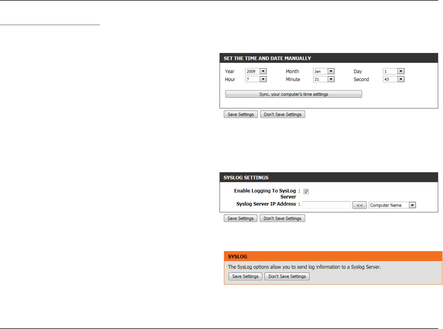
Section 3 - Software Conguration
Set the Time and Date Manually
Here the user can congure the time and date values, used by this router, manually. Here the user can also synchronize the router’s time with the
conguration computer’s time.
The following parameters will be available for conguration:
Set Manually: Here the user can manually congure the date and
time used by this device. Options to congure are
Year, Month, Day, Hour, Minute, and Second.
Click on the Save Settings button to accept the changes made.
Click on the Don’t Save Settings button to discard the changes made.
Syslog
The Syslog options allow you to send log information to a System Log
Server.
The following parameters will be available for conguration:
Enable Logging
To SysLog
Server:
Tick this option to enable the Syslog feature.
Syslog Server IP
Address:
Enter the Syslog Server IP address used here.
Click on the Save Settings button to accept the changes made.
Click on the Don’t Save Settings button to discard the changes made.
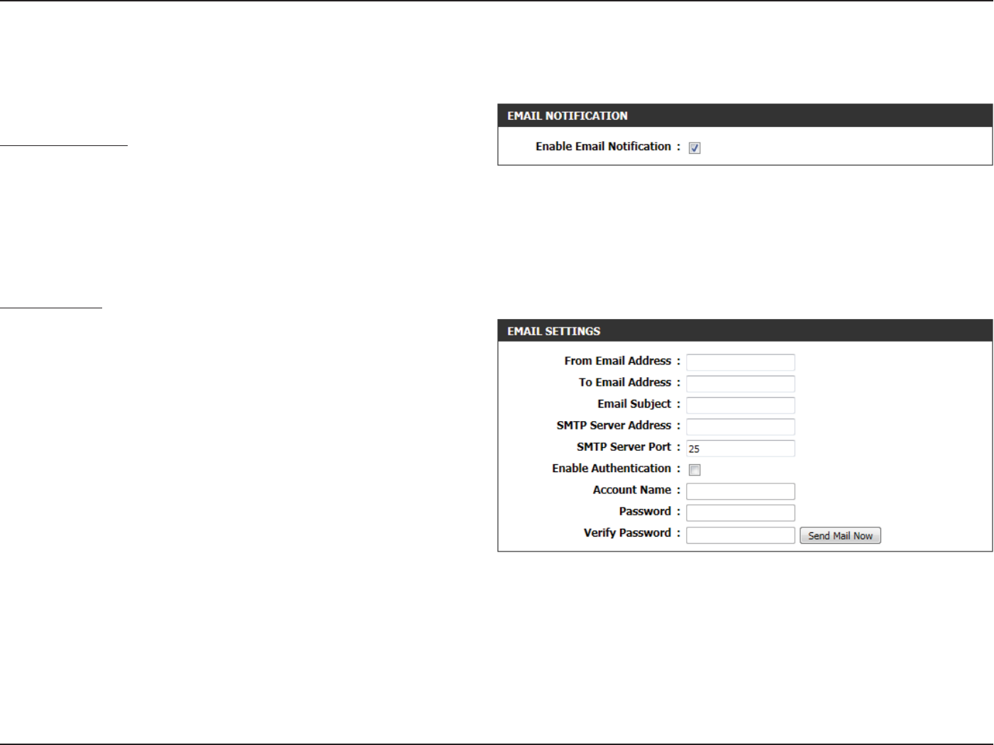
Section 3 - Software Conguration
Email Settings
Email Notication
When this option is enabled, router activity logs or rmware upgrade
notications can be emailed to a designated email address.
The following parameters will be available for conguration:
Enable Email
Notication:
Tick this option to enable the Email notication
feature.
Email Settings
Here this user can manually enter the email settings required to enable
the email notication feature.
The following parameters will be available for conguration:
From Email
Address:
This email address will appear as the sender
when you receive a log le or rmware upgrade
notication via email.
To Email
Address:
Enter the email address where you want the email
sent.
Email Subject: Enter the text that you want to appear in the
subject line of the e-mail that is sent.
SMTP Server
Address:
Enter the SMTP server address for sending email. If your SMTP server requires authentication, select this option.
SMTP Server
Port:
Enter the SMTP server port number used for sending email.
Enable
Authentication:
Tick this option if the SMTP server requires authentication for sending mail.
The Email feature can be used to send the system log les and router alert messages to your email address.
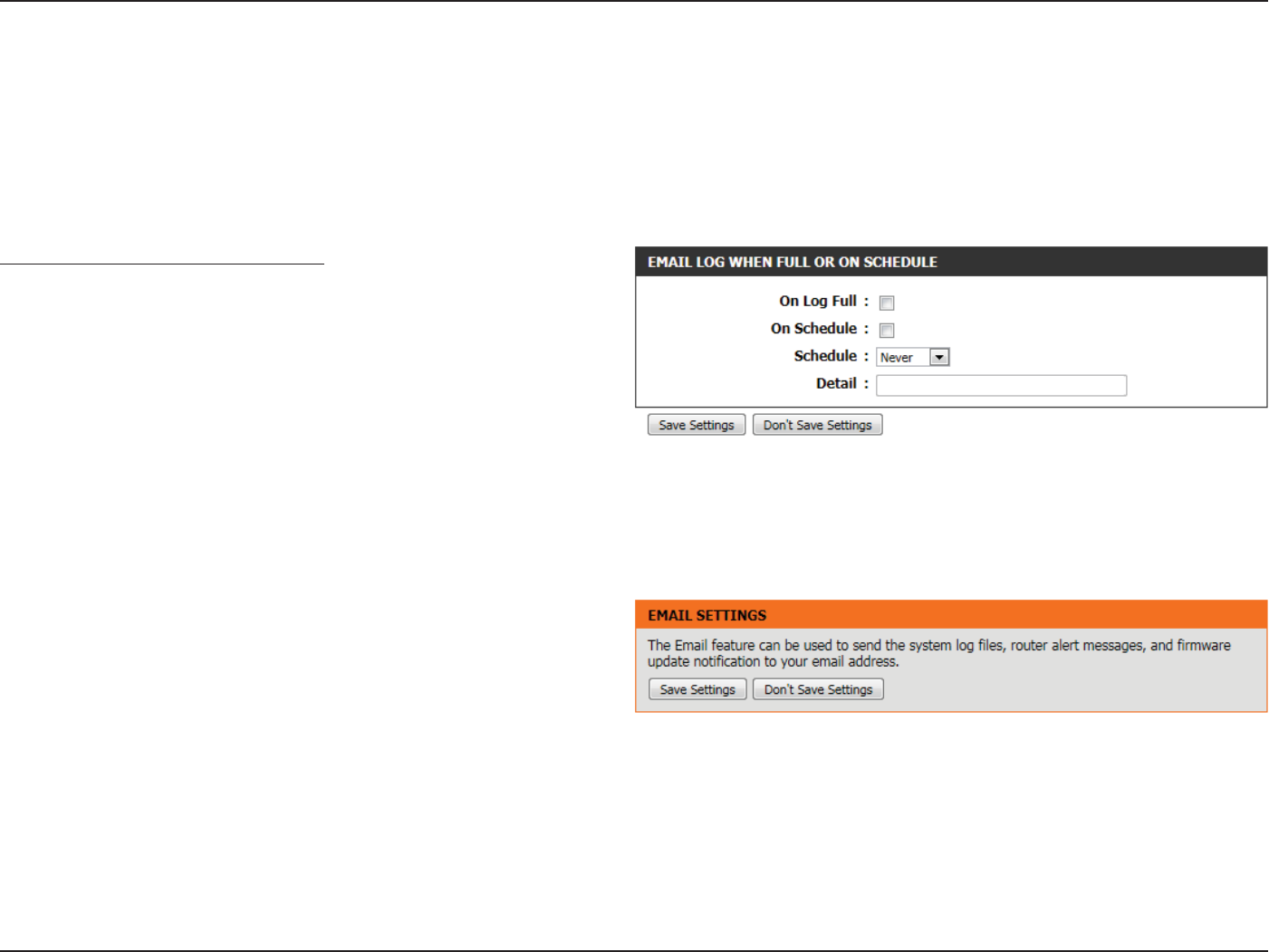
Section 3 - Software Conguration
Email Log When Full or on Schedule
Normally emails are sent at the starting and ending time dened in the
schedule. However, rebooting the router during the schedule period
will cause additional emails to be sent.
The following parameters will be available for conguration:
On Log Full: Select this option if you want logs to be sent by
email when the log is full.
On Schedule: Select this option if you want logs to be sent by email according to a schedule.
Schedule: If you selected the ‘On Schedule’ option, select one of the dened schedule rules. If you do not see the schedule you need in
the list of schedules, go to the Tools > Schedules screen and create a new schedule.
Detail: Enter a detailed description here.
Click on the Save Settings button to accept the changes made.
Click on the Don’t Save Settings button to discard the changes made.
Account Name: Enter your account for sending email.
Password: Enter the password associated with the account.
Verify Password: Re-enter the password associated with the account here.
Send Mail Now: Click this button to send a test email from the Router to verify that the email settings have been congured correctly.
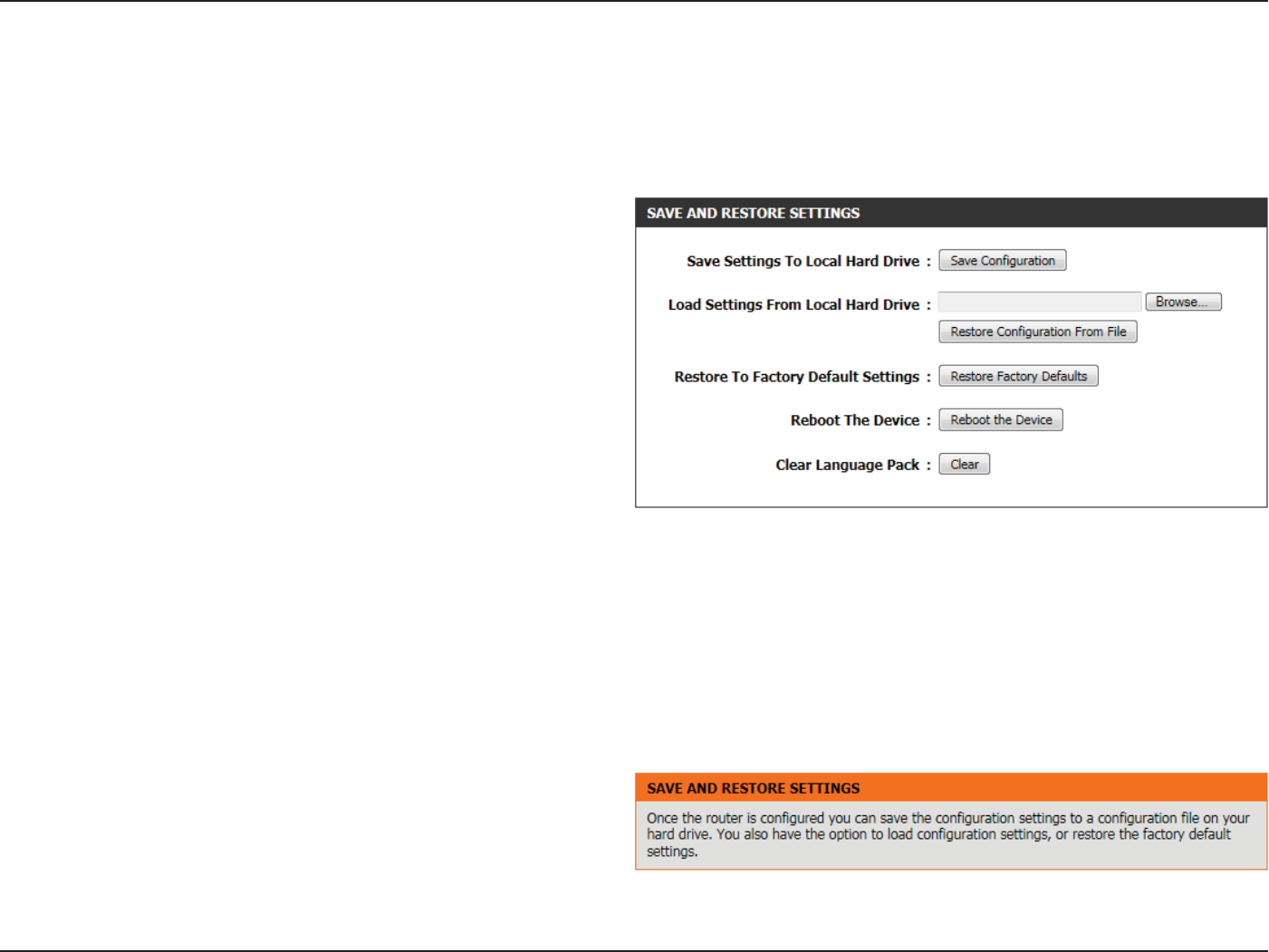
Section 3 - Software Conguration
System
This section allows you to manage the router’s conguration settings, reboot the router, and restore the router to the factory default settings.
Restoring the unit to the factory default settings will erase all settings, including any rules that you’ve created.
The following parameters will be available for conguration:
Save Settings To
Local Hard Drive:
Use this option to save the current router
conguration settings to a le on the hard disk of
the computer you are using. First, click the Save
button. A le dialog will appear, allowing you to
select a location and le name for the settings.
Load Settings
From Local Hard
Drive:
Use this option to load previously saved router
conguration settings. First, use the Browse option
to nd a previously saved le of conguration
settings. Then, click the Restore Conguration
From File button below to transfer those settings
to the router.
Restore To
Factory Default
Settings:
This option will restore all conguration settings
back to the settings that were in eect at the
time the router was shipped from the factory.
Any settings that have not been saved will be
lost, including any rules that you have created. If
you want to save the current router conguration
settings, use the Save button above.
Reboot The
Device:
Click to reboot the router.
Clear Language
Pack:
If you previously installed a language pack and want to revert all the menus on the Router interface back to the default
language settings, click the Clear button.
Click on the Save Settings button to accept the changes made.
Click on the Don’t Save Settings button to discard the changes made.
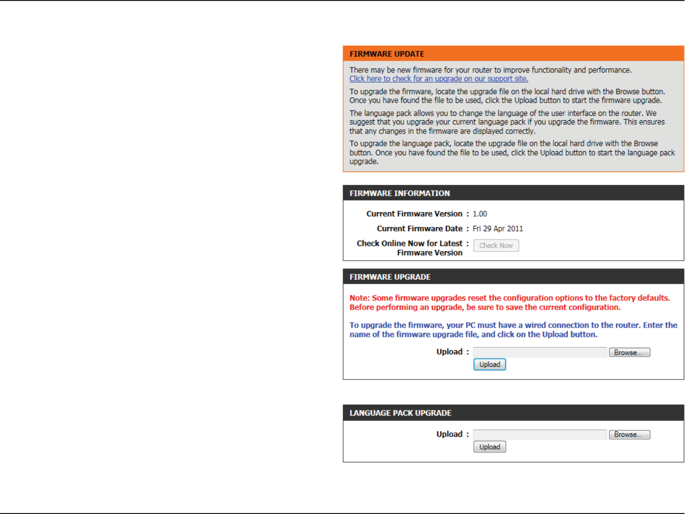
Section 3 - Software Conguration
Firmware
Use the Firmware window to upgrade the rmware of the Router and
install language packs. If you plan to install new rmware, make sure
the rmware you want to use is on the local hard drive of the computer.
If you want to install a new language pack, make sure that you have
the language pack available. Please check the support site for rmware
updates. You can download rmware upgrades to your hard drive from
the support site.
In the Firmware Information section the user can view the Current
Firmware Version number running on this device, the Current Firmware
Date of this same rmware version running on this device, and a button
to click that will Check Online Now for Latest Firmware Version.
In the Firmware Upgrade section the user can physically upgrade the
rmware of this device clicking on the Browse button and navigating
to the rmware le, saved on the local hard drive. After locating the le,
click on the Upload button to initiate the rmware upgrade.
Note: Some rmware upgrades will reset the conguration, of the
device, to factory defaults. Be sure to save the current conguration rst
before any rmware update.
In the Language Pack Upgrade section, the user can change the router’s
language pack by clicking on the Browse button and navigating to the
language pack, downloaded to the computer. After navigating to the
language pack le, click on the Upload button to initiate the language
pack upload and conguration. Always keep a close lookout on the
local vendor’s website for new rmware upgrades and language packs.
Note: Always update the rmware or language packs for this device using the wired connection. Never upgrade using a wireless connection.
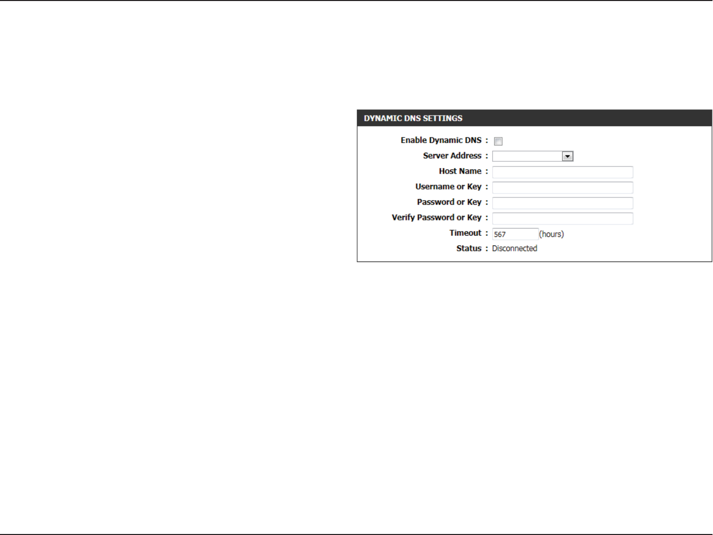
Section 3 - Software Conguration
Dynamic DNS
The DDNS feature allows you to host a server (Web, FTP, Game Server, etc…) using a domain name that you have purchased (www.
whateveryournameis.com) with your dynamically assigned IP address. Most broadband Internet Service Providers assign dynamic (changing) IP
addresses. Using a DDNS service provider, your friends can enter in your domain name to connect to your server no matter what your IP address is.
The following parameters will be available for conguration:
Enable Dynamic
DNS:
Dynamic Domain Name System is a method of
keeping a domain name linked to a changing IP
Address. Check the box to enable DDNS.
Server Address: Choose your DDNS provider from the drop down
menu.
Host Name: Enter the Host Name that you registered with your
DDNS service provider.
Username or
Key:
Enter the Username or Key for your DDNS account.
Password or Key: Enter the Password or Key for your DDNS account.
Verify Password
or Key:
Re-enter the Password or Key for your DDNS
account.
Timeout: Enter the timeout value used for the DDNS account
here.
Status: Displays the DDNS connection status here.
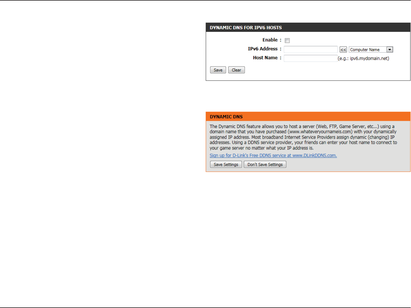
Section 3 - Software Conguration
The following parameters will be available for conguration:
Enable: Tick this option to enable the Dynamic DNS feature
for IPv6 hosts.
IPv6 Address: Enter the IPv6 Address used here. Alternatively,
the user can select the Computer Name for the
drop-down list and click on the << button to add
it the IPv6 Address eld.
Host Name: Enter the IPv6 host name used for the DDNS
account here.
Click on the Save button to add the IPv6 host to the IPv6 Dynamic DNS
List.
Click on the Clear button to clear the information entered in the elds.
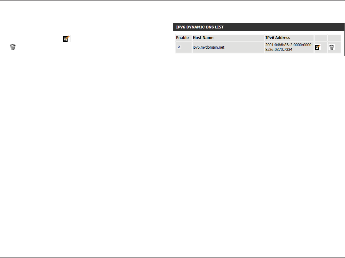
Section 3 - Software Conguration
In the IPv6 Dynamic DNS List section, a list of IPv6 hosts will be
displayed. Tick the Enable checkbox to make the host active. To edit a
specic entry click on the icon. To remove a specic entry, click on
the icon.
Click on the Save Settings button to accept the changes made.
Click on the Don’t Save Settings button to discard the changes made.
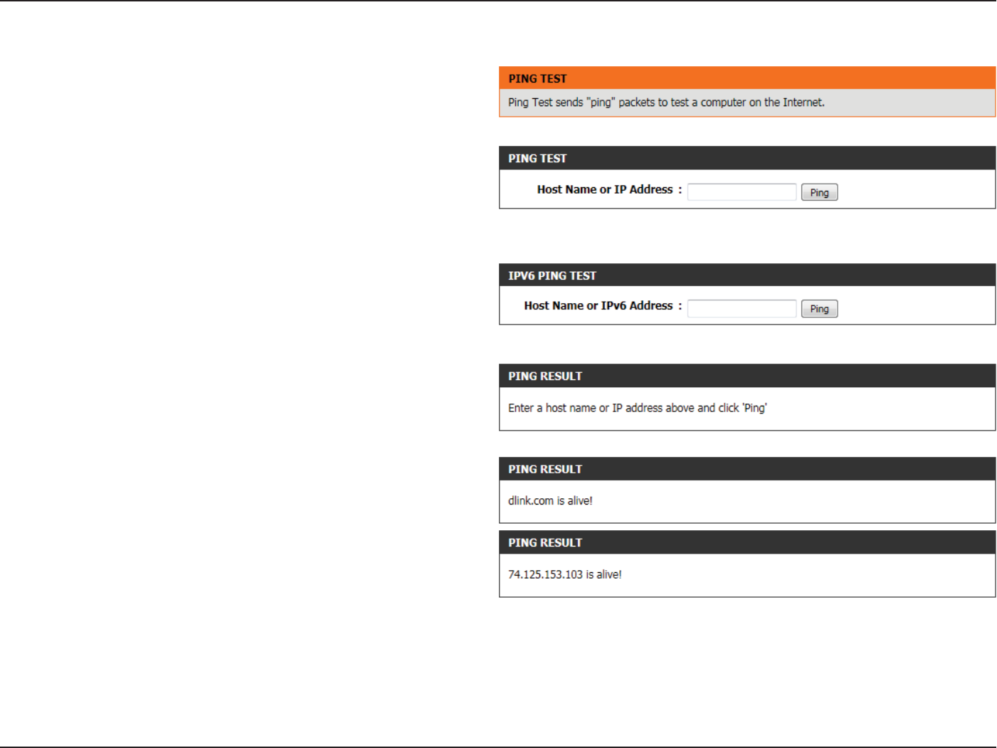
Section 3 - Software Conguration
System Check
This useful diagnostic utility can be used to check if a computer is on the
Internet. It sends ping packets and listens for replies from the specic
host.
In the Ping Test section the user can test the Internet connectivity by
entering in a host name or the IP address that you want to Ping and click
on the Ping button. The status of your Ping attempt will be displayed in
the Ping Result box.
In the IPv6 Ping Test section the user can test the Internet connectivity
by entering in a host name or the IPv6 address that you want to Ping
and click on the Ping button. The status of your Ping attempt will be
displayed in the Ping Result box.
In the Ping Result section the results of the attempted ping will be
displayed.
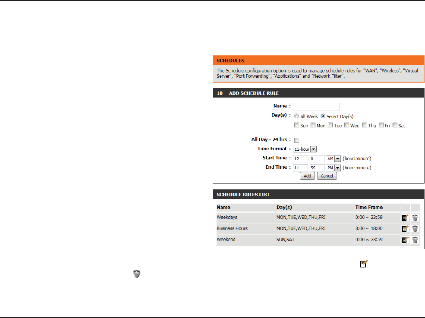
Section 3 - Software Conguration
Schedules
The following parameters will be available for conguration:
Name: Enter the custom name for the new schedule rule
here. This name is used for identication.
Day(s): To use every day in the week for this rule, select
the All Week option. To use only selected days for
this rule, select the Select Day(s) option and tick
the appropriate days used for this rule.
All Day - 24 hrs: To enable this rule to run 24 hours instead of only
a certain part of the day, tick this option.
Time Format: Select the appropriate time format to use here.
Start Time: If the All Day option is not selected, the user can
enter the starting time here.
End Time: If the All Day option is not selected, the user can
enter the ending time here.
Click on the Add button to add this new rule to the schedule rules list.
Click on the Cancel button to discard the information and cancel the
rule addition.
In the Schedule Rules List section, the user can view the available schedule rules created. To edit an existing rule, click on the icon of the specic
entry, To remove an existing rule, click on the icon of the specic entry.
Schedules can be created for use with enforcing rules. For example, if you want to restrict web access to Mon-Fri from 3pm to 8pm, you could
create a schedule selecting Mon, Tue, Wed, Thu, and Fri and enter a Start Time of 3pm and End Time of 8pm.

Section 3 - Software Conguration
Status Category
In this category the user will be able to view information regarding the conguration and functionality of this device. The information includes
WAN, LAN and Wireless congurations, System, Firewall, Router logs, and more.
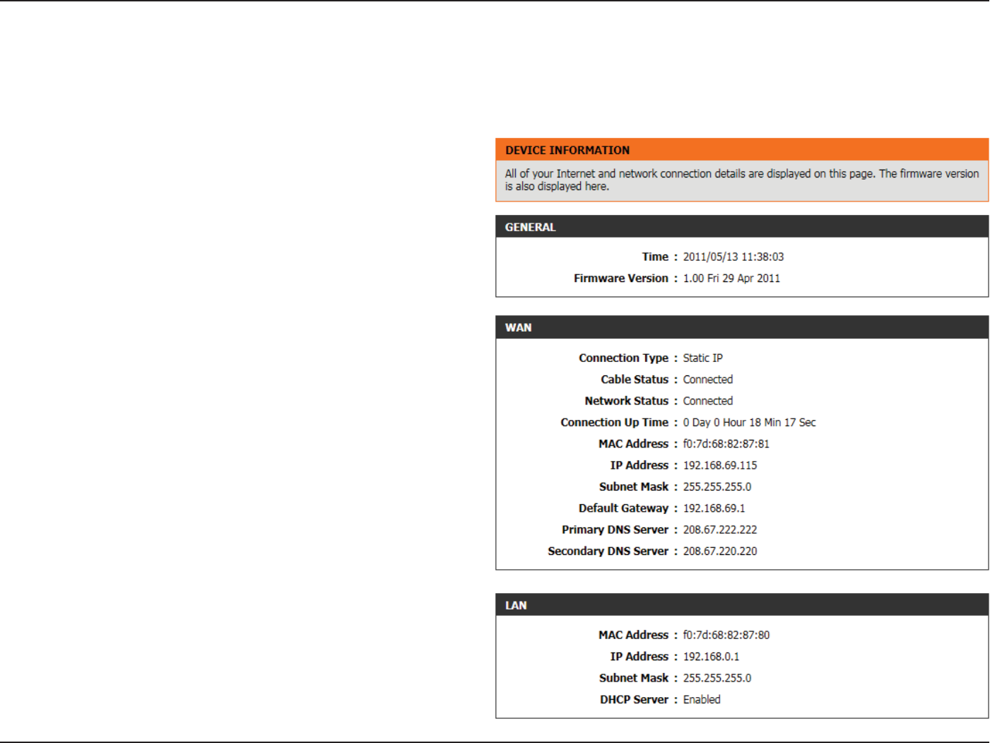
Section 3 - Software Conguration
Device Info
This page displays the current information for the router. It will display the LAN, WAN (Internet), and Wireless information. If your Internet connection
is set up for a Dynamic IP address then a Release button and a Renew button will be displayed. Use Release to disconnect from your ISP and use
Renew to connect to your ISP.
In the General section, information about the time and rmware is
being displayed.
In the WAN section, information about the Internet connection is being
displayed.
In the LAN section, information about the Local Area Network
conguration is being displayed.
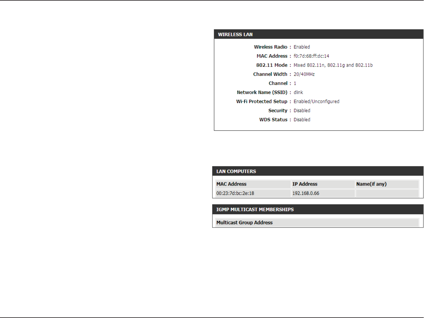
Section 3 - Software Conguration
In the Wireless LAN section, information about the Wireless Local Area
Network conguration is being displayed.
In the LAN Computers section, a list of actively connected nodes are
being displayed.
In the IGMP Multicast Memberships section, a list of Multicast Group
Addresses are being displayed.
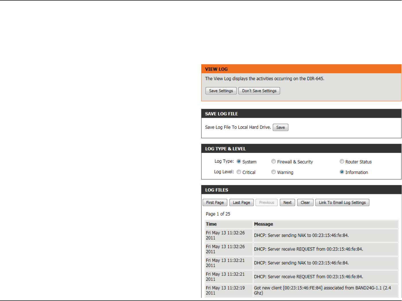
Section 3 - Software Conguration
Logs
The router automatically logs (records) events of possible interest in it’s internal memory. If there isn’t enough internal memory for all events, logs
of older events are deleted but logs of the latest events are retained. The Logs option allows you to view the router logs. You can dene what types
of events you want to view and the level of the events to view. This router also has external Syslog Server support so you can send the log les to
a computer on your network that is running a Syslog utility.
The following parameters will be available for conguration:
Log Type: Use the radio buttons to select the types of
messages that you want to display from the log.
System, Firewall & Security, and Router Status
messages can be selected.
Log Level: There are three levels of message importance:
Critical, Warning, and Information. Select the
levels that you want displayed in the log.
The following parameters will be available for conguration:
First - Last Page: Use these buttons to navigate to the rst or last
page of the router logs.
Previous - Next: Use these buttons to navigate to the next or
previous page of the router logs.
Clear: Click on this button to clear all the contents from
the log.
Link to Email Log
Settings:
Click this button to open the Email Settings screen
so that you can change the Email conguration for
sending logs.
In the Save Log File section, the user can click on the Save button save
the Router’s log entries to a log le on your computer.
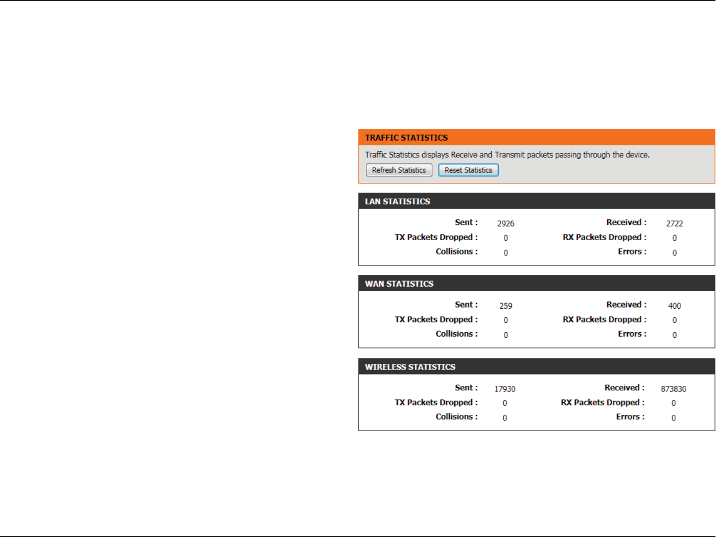
Section 3 - Software Conguration
Statistics
In the LAN Statistics section, the user can view the trac statistics that
occurred on the LAN interface. Information that is displayed includes the
packets sent and received, packets dropped, collisions that occurred,
and error packets sent and received.
In the WAN Statistics section, the user can view the trac statistics that
occurred on the WAN interface. Information that is displayed includes
the packets sent and received, packets dropped, collisions that occurred,
and error packets sent and received.
In the Wireless Statistics section, the user can view the trac statistics
that occurred on the Wireless interface. Information that is displayed
includes the packets sent and received, packets dropped, collisions that
occurred, and error packets sent and received.
Click on the Refresh Statistics button to refresh the display page.
Click on the Reset Statistics button to clear all the statistic information
for all the elds displayed.
The screen below displays the Trac Statistics. Here you can view the amount of packets that pass through the router on both the WAN, LAN ports
and the 802.11n/g (2.4GHz) wireless band. The trac counter will reset if the device is rebooted.
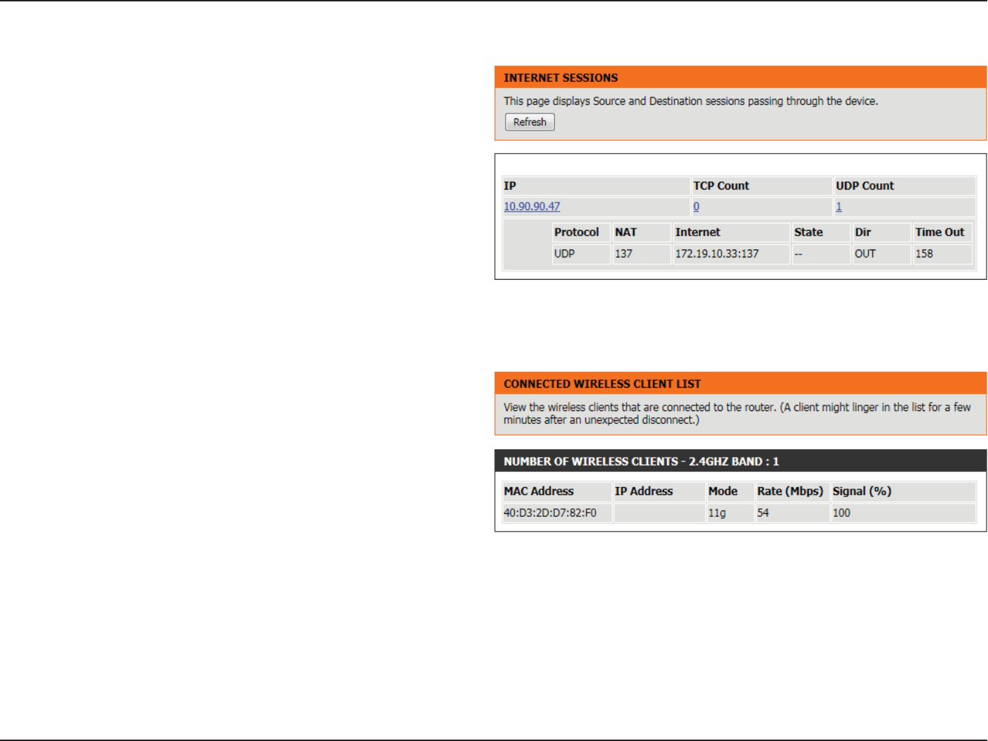
Section 3 - Software Conguration
Internet Sessions
The Internet Sessions page displays full details of active Internet sessions
through your router. An Internet session is a conversation between
a program or application on a LAN-side computer and a program or
application on a WAN-side computer.
In the section all the active Internet sessions will be displayed.
Wireless
The wireless client table displays a list of current connected wireless
clients. This table also displays the connection time and MAC address of
the connected wireless clients.
In the Number of Wireless Clients - 2.4GHz Band section a list of 2.4GHz
active wireless clients will be displayed.
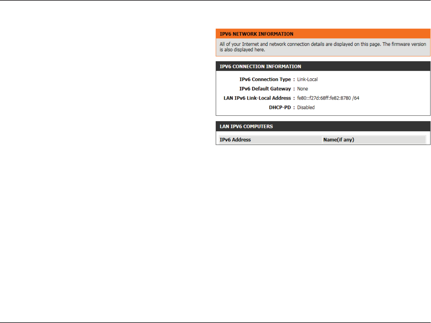
Section 3 - Software Conguration
IPv6
The IPv6 page displays a summary of the Router’s IPv6 settings and lists
the IPv6 address and host name of any IPv6 clients.
In the IPv6 Connection Information section, more information about
the IPv6 connection will be displayed. Information like the connection
type, gateway address, Link-Local address, DNS Servers, and more.
In the LAN IPv6 Computers section, a list of actively connected LAN
IPv6 computers will be displayed.

Federal Communication Commission Interference Statement:
This device complies with Part 15 of the FCC Rules. Operation is subject to the following two conditions: (1) This device may
not cause harmful interference, and (2) this device must accept any interference received, including interference that may
cause undesired operation.
This equipment has been tested and found to comply with the limits for a Class B digital device, pursuant to Part 15 of the
FCC Rules. These limits are designed to provide reasonable protection against harmful interference in a residential installa-
tion. This equipment generates, uses and can radiate radio frequency energy and, if not installed and used in accordance
with the instructions, may cause harmful interference to radio communications. However, there is no guarantee that inter-
ference will not occur in a particular installation. If this equipment does cause harmful interference to radio or television
reception, which can be determined by turning the equipment o and on, the user is encouraged to try to correct the inter-
ference by one of the following measures:
- Reorient or relocate the receiving antenna.
- Increase the separation between the equipment and receiver.
- Connect the equipment into an outlet on a circuit dierent from that to which the receiver is connected.
- Consult the dealer or an experienced radio/TV technician for help.
FCC Caution: Any changes or modications not expressly approved by the party responsible for compliance could void the
user's authority to operate this equipment.
This transmitter must not be co-located or operating in conjunction with any other antenna or transmitter.

Radiation Exposure Statement:
This equipment complies with FCC radiation exposure limits set forth for an uncontrolled environment. This equipment
should be installed and operated with minimum distance 20cm between the radiator & your body.
Note: The country code selection is for non-US model only and is not available to all US model. Per FCC regulation, all WiFi
product marketed in US must xed to US operation channels only.
Industry Canada statement:
Radiation Exposure Statement:
This device complies with RSS-210 of the Industry Canada Rules. Operation is subject to the following two conditions: (1)
This device may not cause harmful interference, and (2) this device must accept any interference received, including inter-
ference that may cause undesired operation.
Ce dispositif est conforme à la norme CNR-210 d'Industrie Canada applicable aux appareils radio exempts de licence. Son
fonctionnement est sujet aux deux conditions suivantes: (1) le dispositif ne doit pas produire de brouillage préjudiciable, et
(2) ce dispositif doit accepter tout brouillage reçu, y compris un brouillage susceptible de provoquer un fonctionnement
indésirable.
This equipment complies with IC radiation exposure limits set forth for an uncontrolled environment. This equipment
should be installed and operated with minimum distance 20cm between the radiator & your body.
Déclaration d'exposition aux radiations:
Cet équipement est conforme aux limites d'exposition aux rayonnements IC établies pour un environnement non contrôlé.
Cet équipement doit être installé et utilisé avec un minimum de 20 cm de distance entre la source de rayonnement et votre
corps.
FOR COUNTRY CODE SELECTION USAGE (WLAN DEVICES)