D Link PR1040A1 1USB2.0 port MFP Print Server User Manual 2 of 2
D Link Corporation 1USB2.0 port MFP Print Server 2 of 2
UserManual.wiki
>
D Link
>
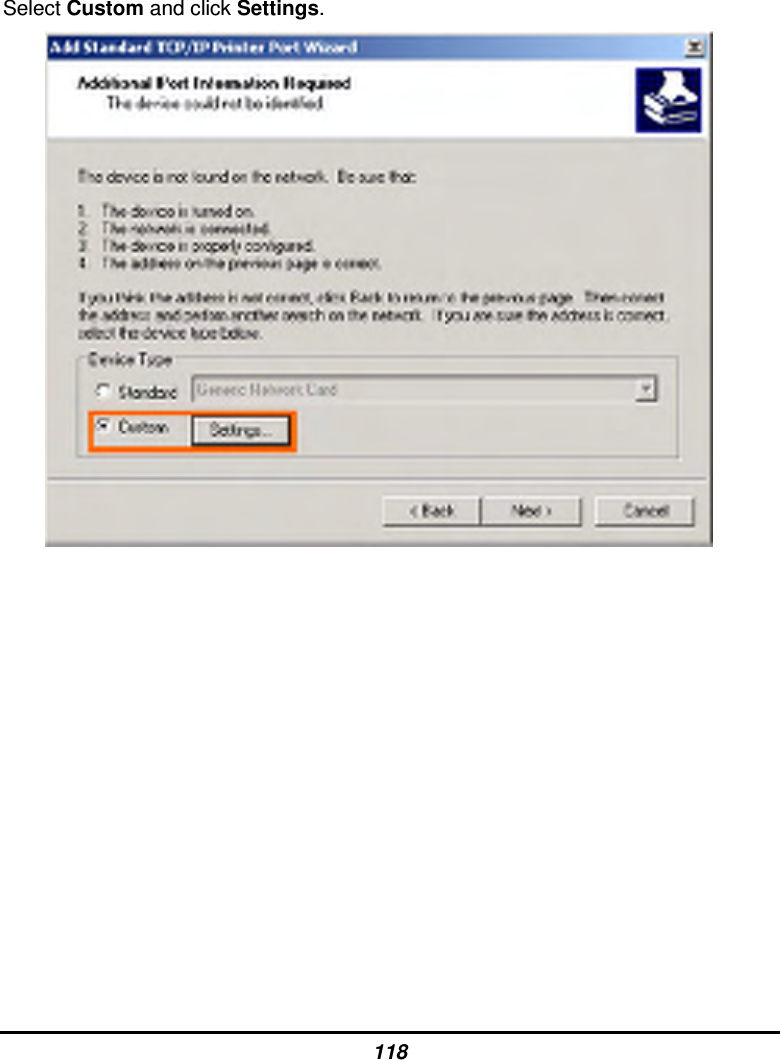
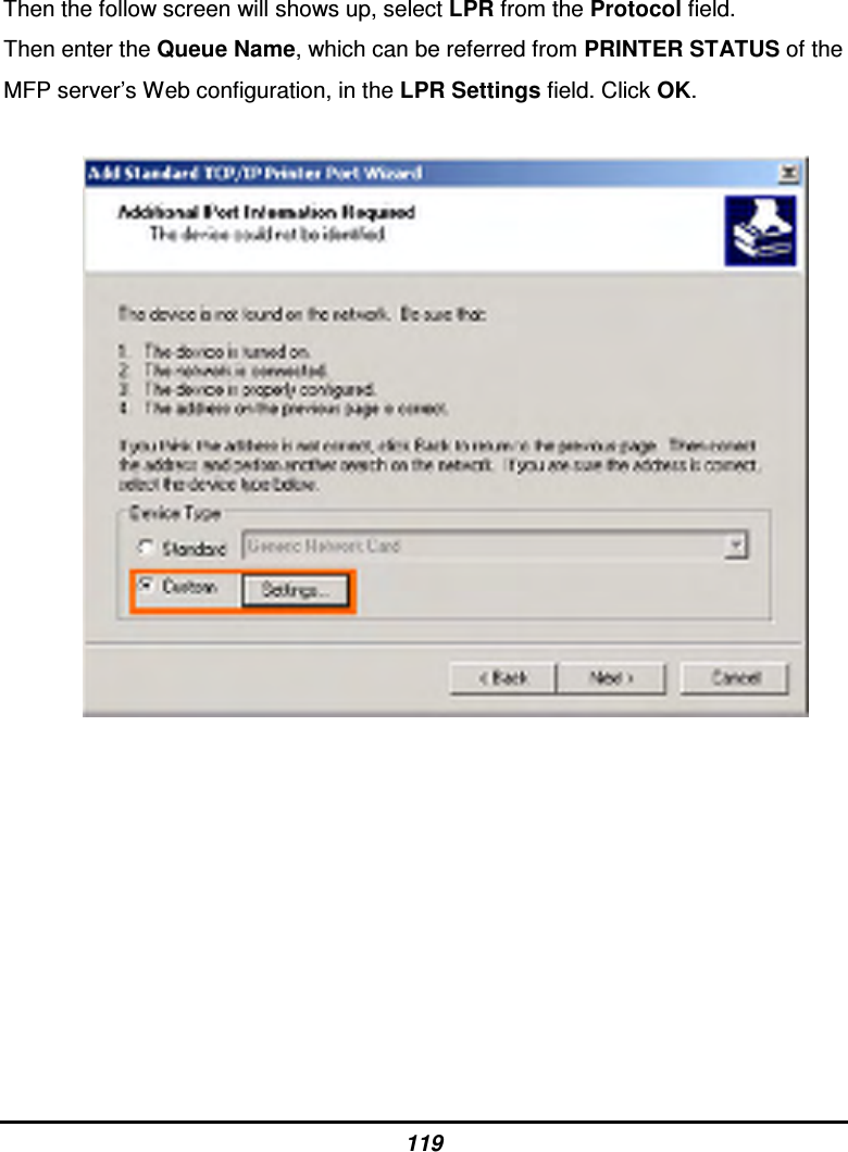
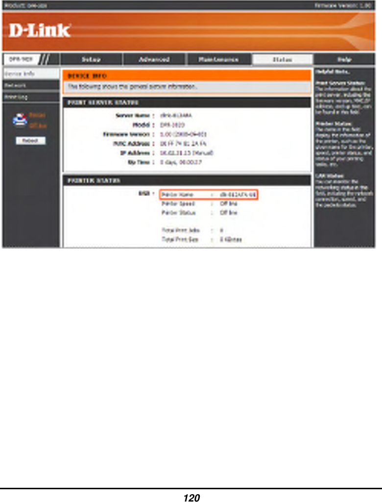
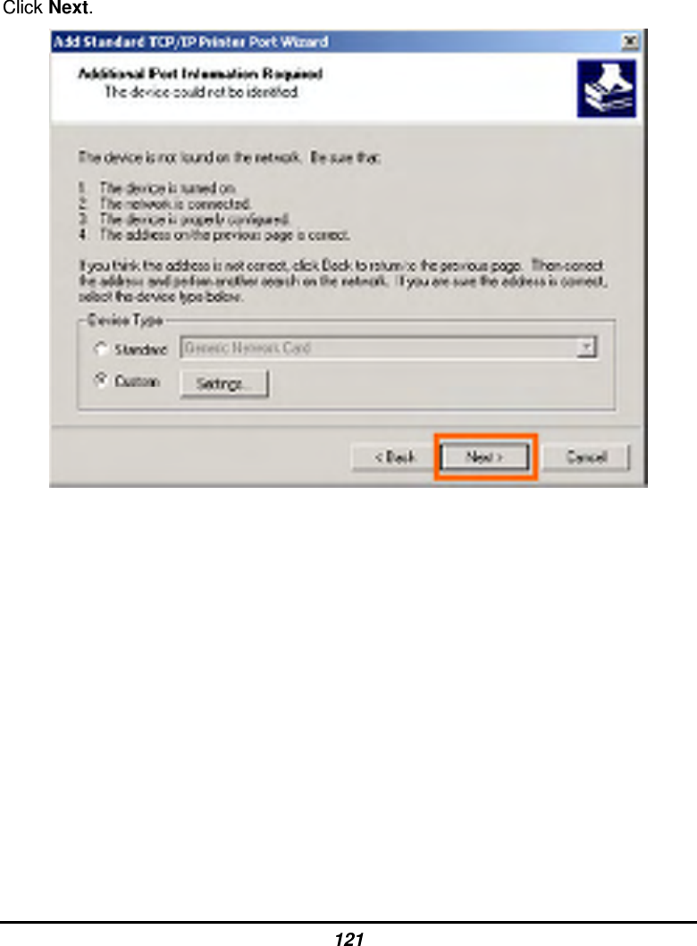
PR1040A1 User Manual
>
User manual 2 of 2
Contents
1.
User manual 1 of 2
2.
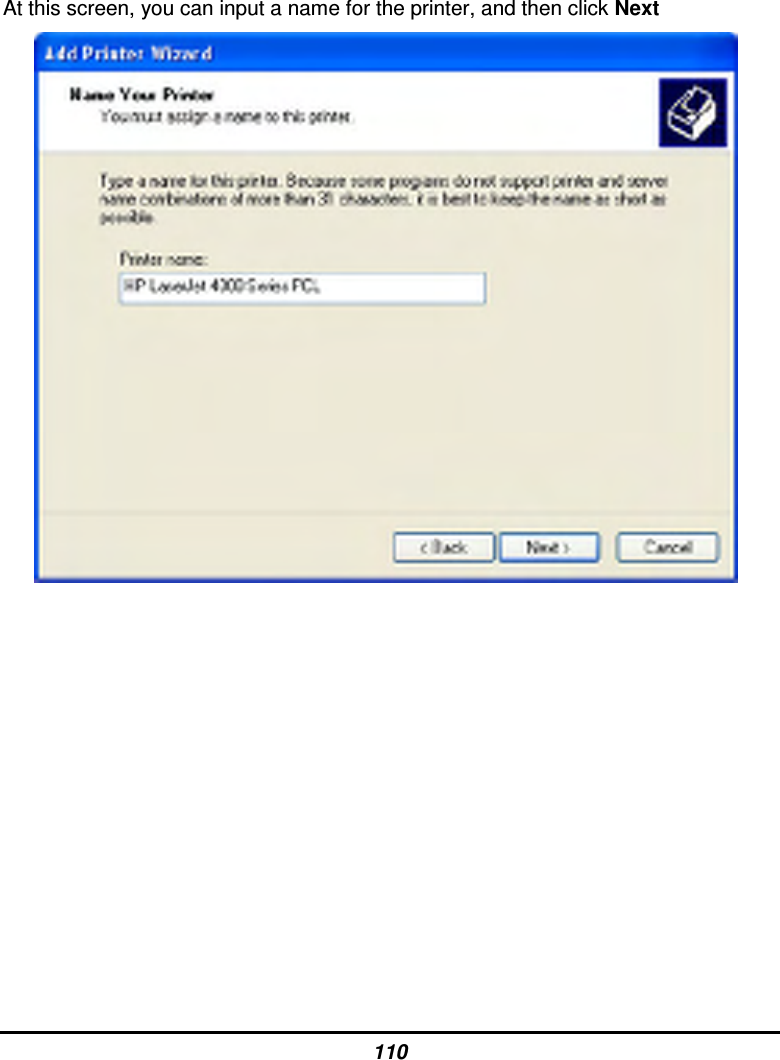
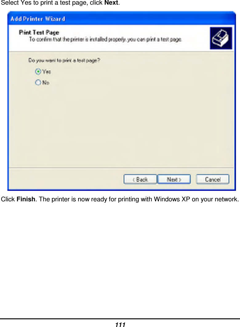
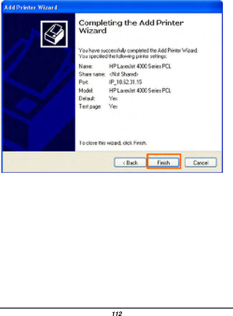
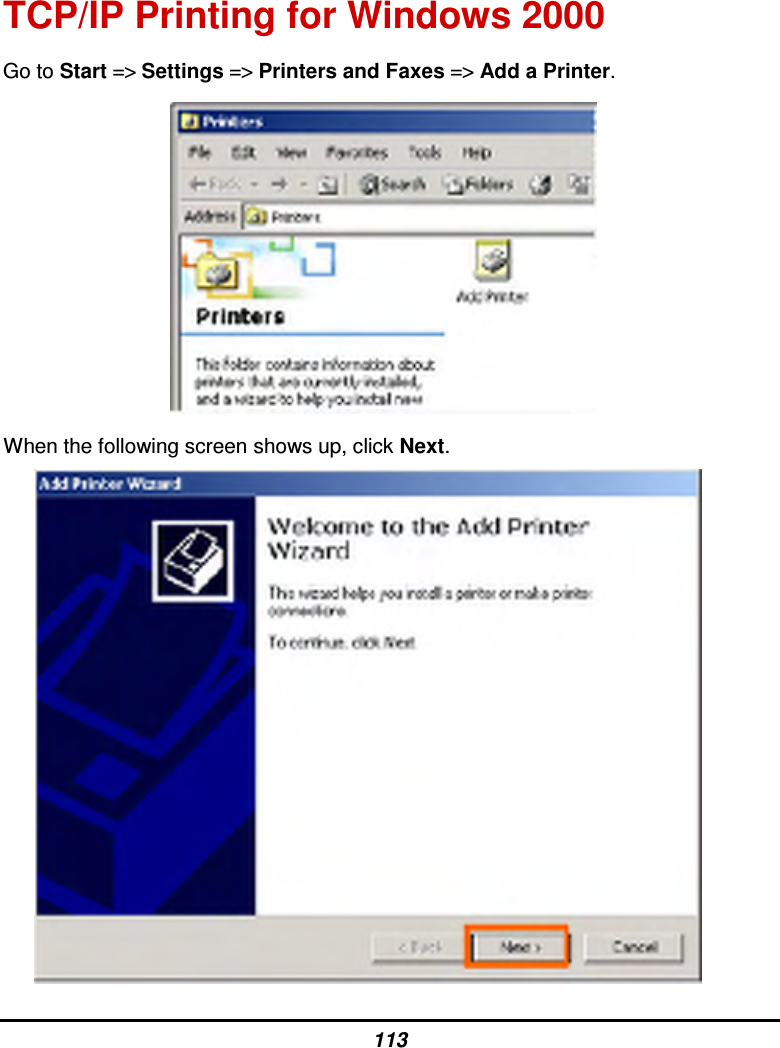
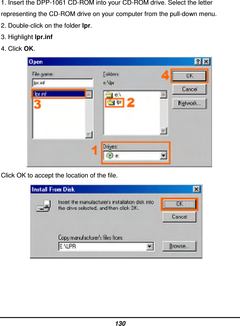
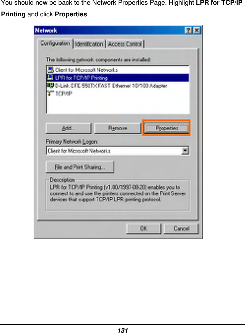
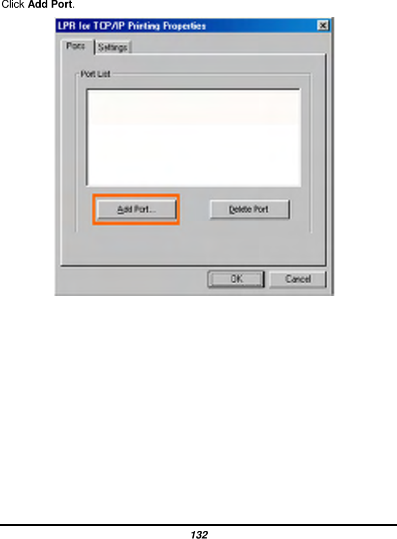
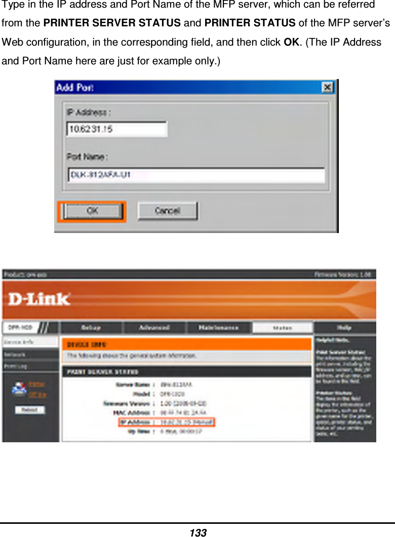
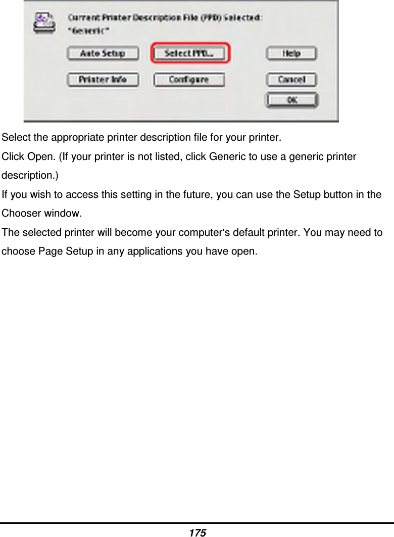
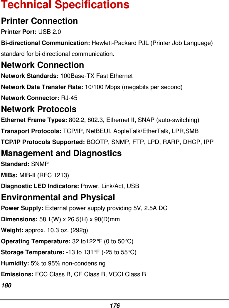
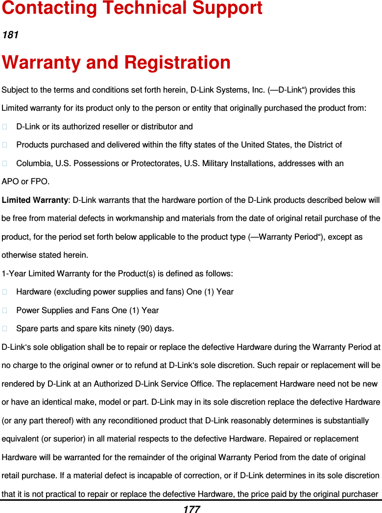
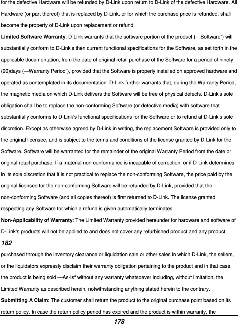
User manual 2 of 2
User manual 2 of 2
Navigation menu
Upload a User Manual
Namespaces
Wiki Guide
HTML
PDF
Info
Views
User Manual
Discussion / Help
Navigation