D Link PR1040A1 1USB2.0 port MFP Print Server User Manual 2 of 2
D Link Corporation 1USB2.0 port MFP Print Server 2 of 2
D Link >
Contents
- 1. User manual 1 of 2
- 2. User manual 2 of 2
User manual 2 of 2
93
94
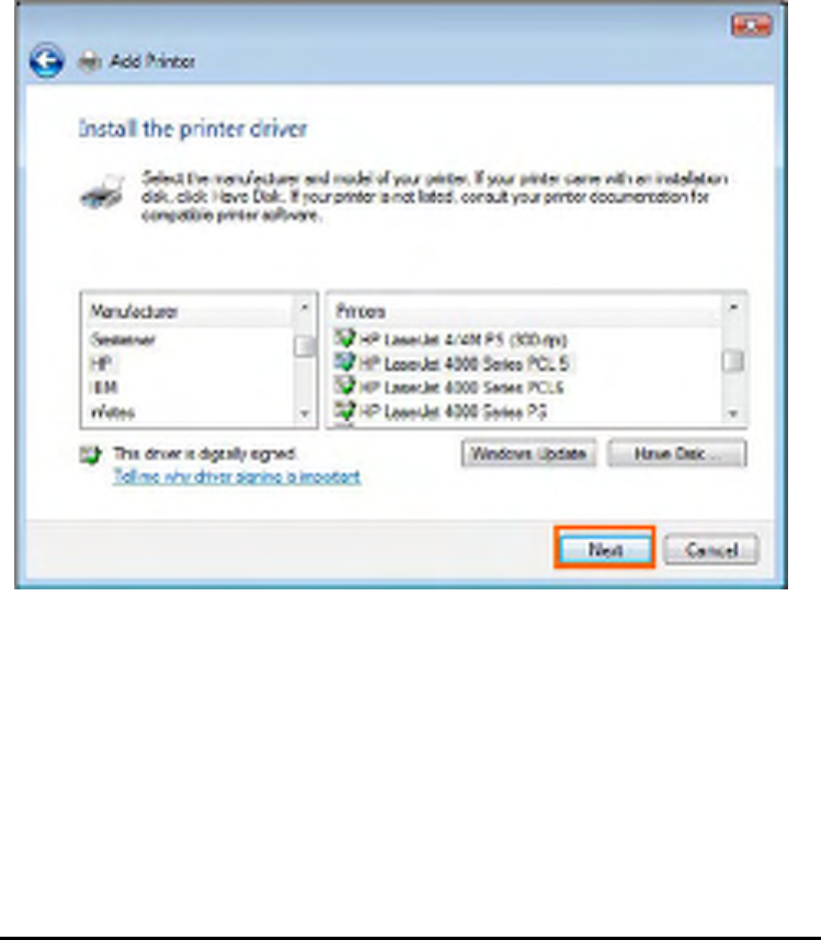
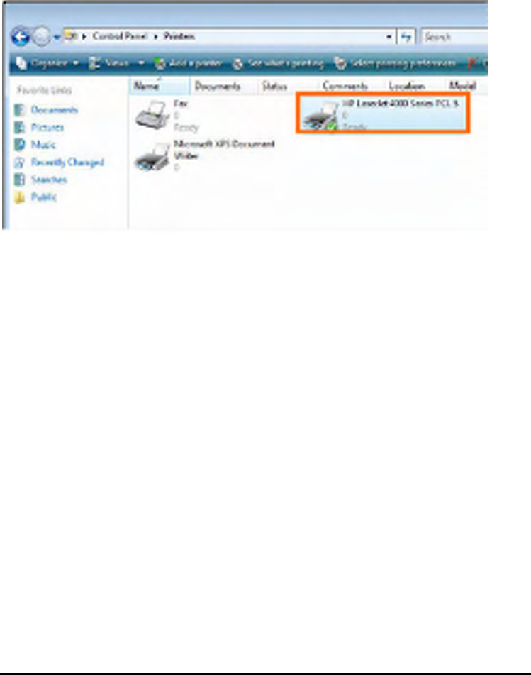
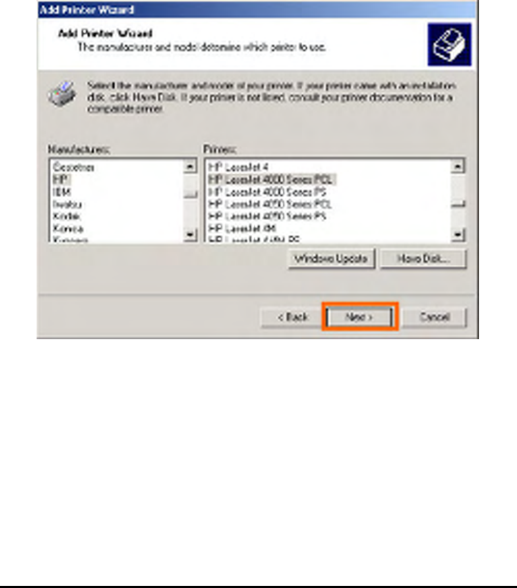
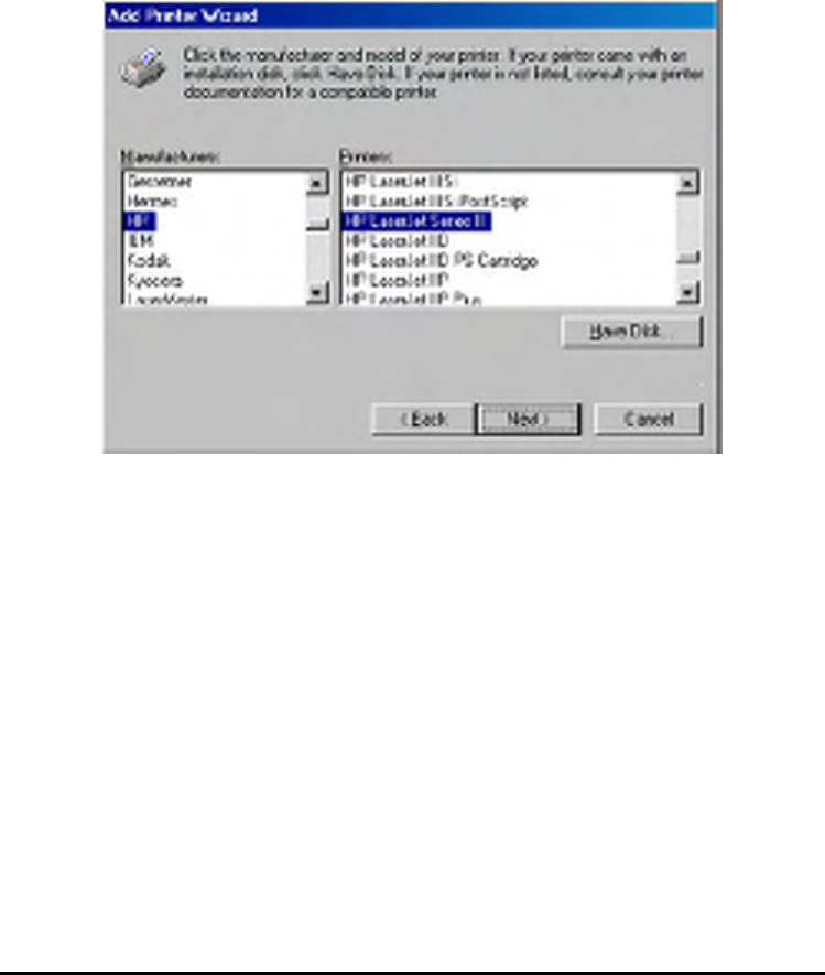
Highlight the printer, as shown. If the desired printer is not on the list, click Have
Disk and insert the printer driver disk that came with your printer to install the printer
drivers.
Click Next
95
Click Next to start installing the printer.
96
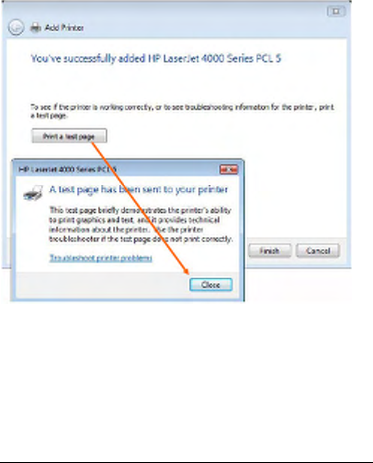
After clicked Print a test page, a small dialogue box will show up as below. Click
Close.
97
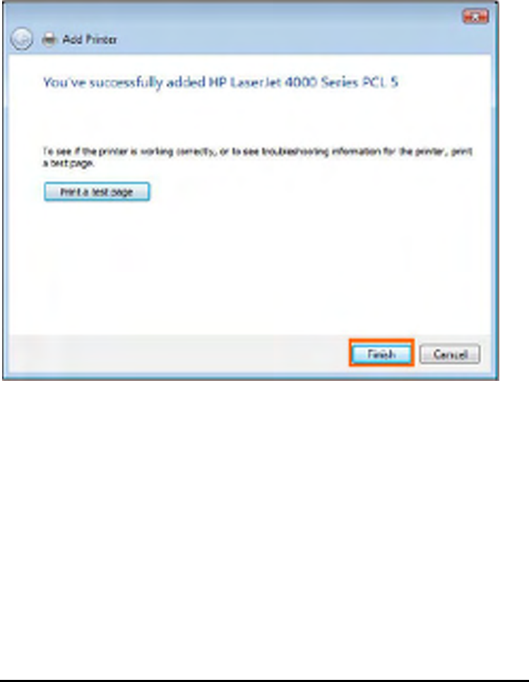
Click Finish.
98
The printer is now ready for printing with Windows Vista on your network.
99
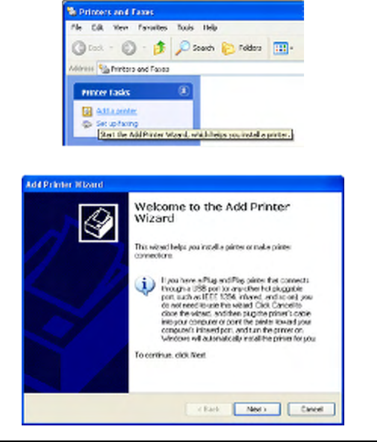
TCP/IP Printing for Windows XP
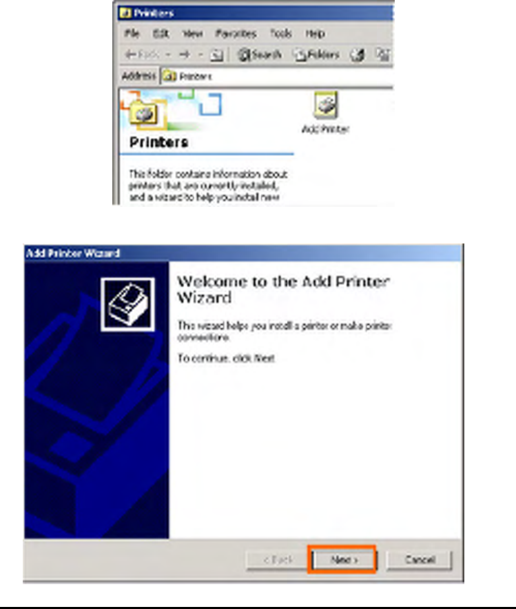
Go to Start => Printers and Faxes => Add a Printer.
When the following screen shows up, click Next.
100
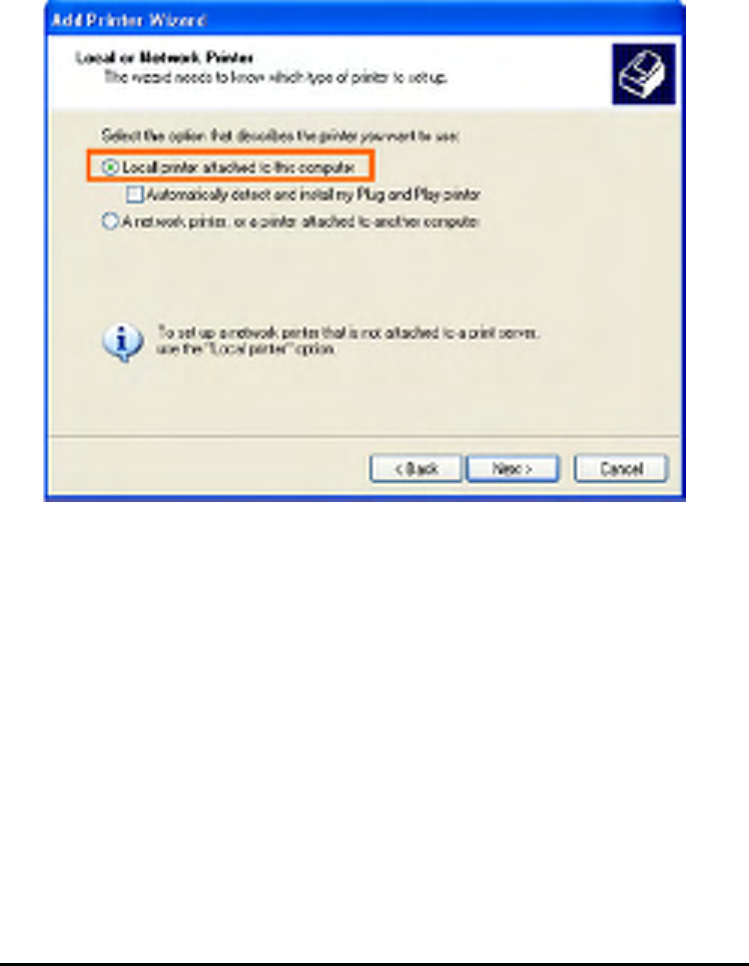
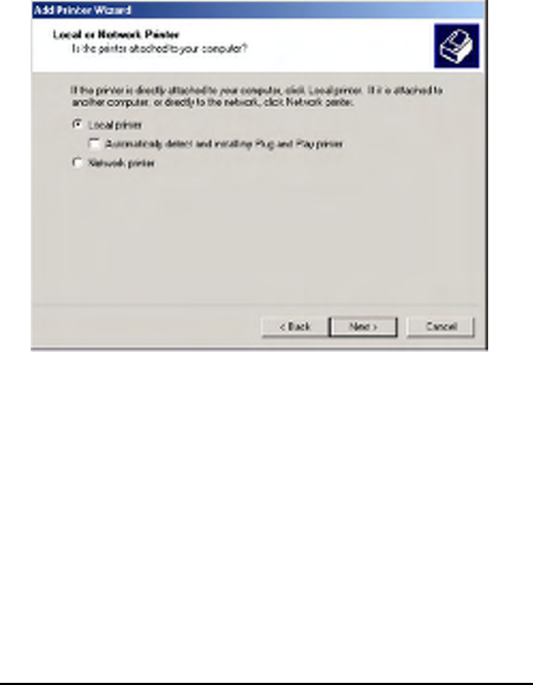
Select the first option, Local printer attached to this computer, and click Next.
101
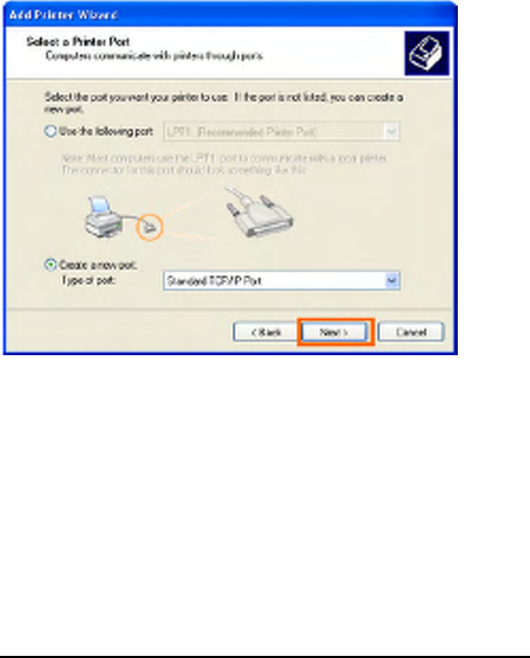
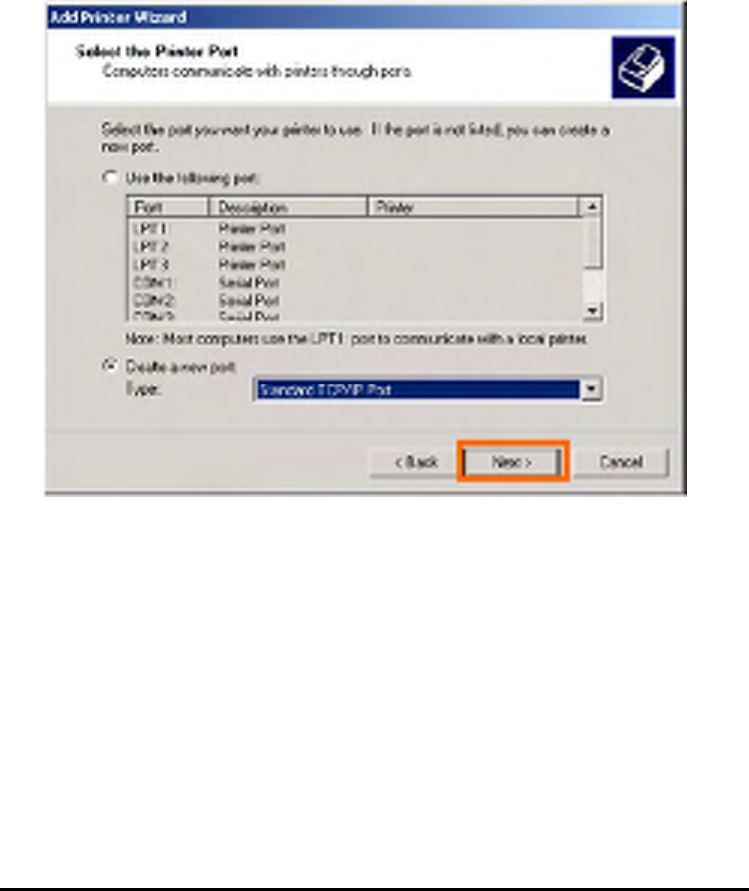
Select the second option, Create a new port, and highlight Standard TCP/IP Port
from the pull-down menu. Click Next.
102
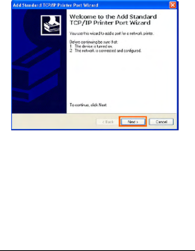
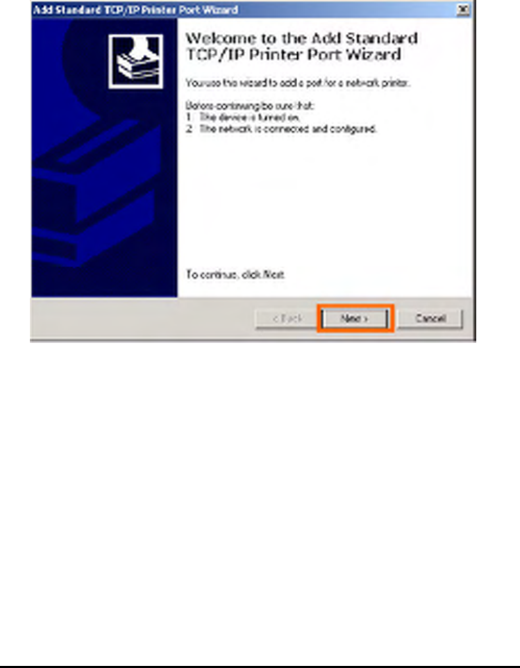
Click Next.
103
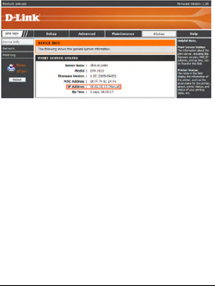
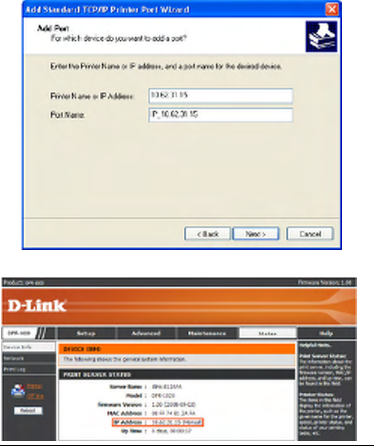
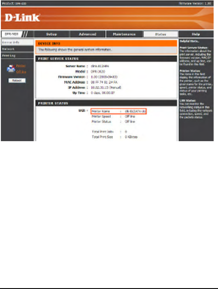
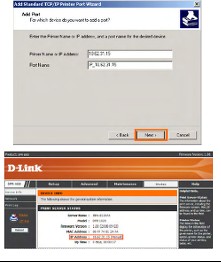
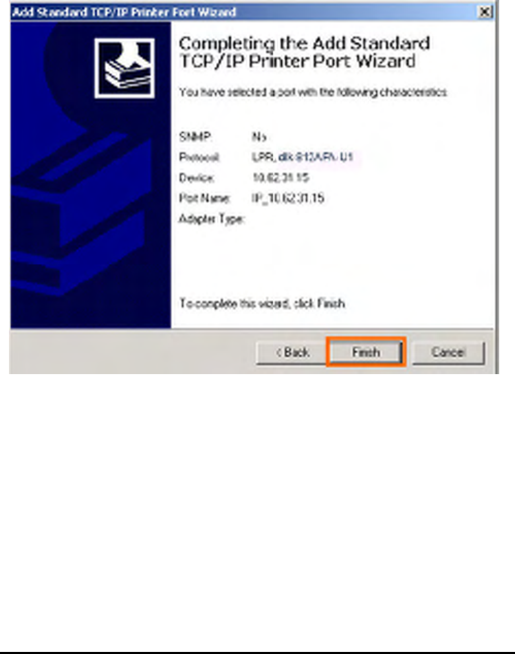
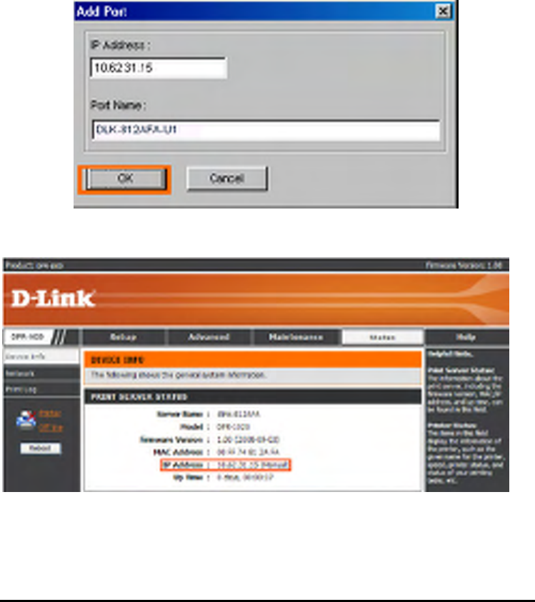
Type the IP address of the MFP server (e.g. 10.62.31.15 used in this manual), which
can be referred from the PRINTER SERVER STATUS of the MFP server’s Web
configuration, and then the Port Name will automatically be filled in. Click Next
104
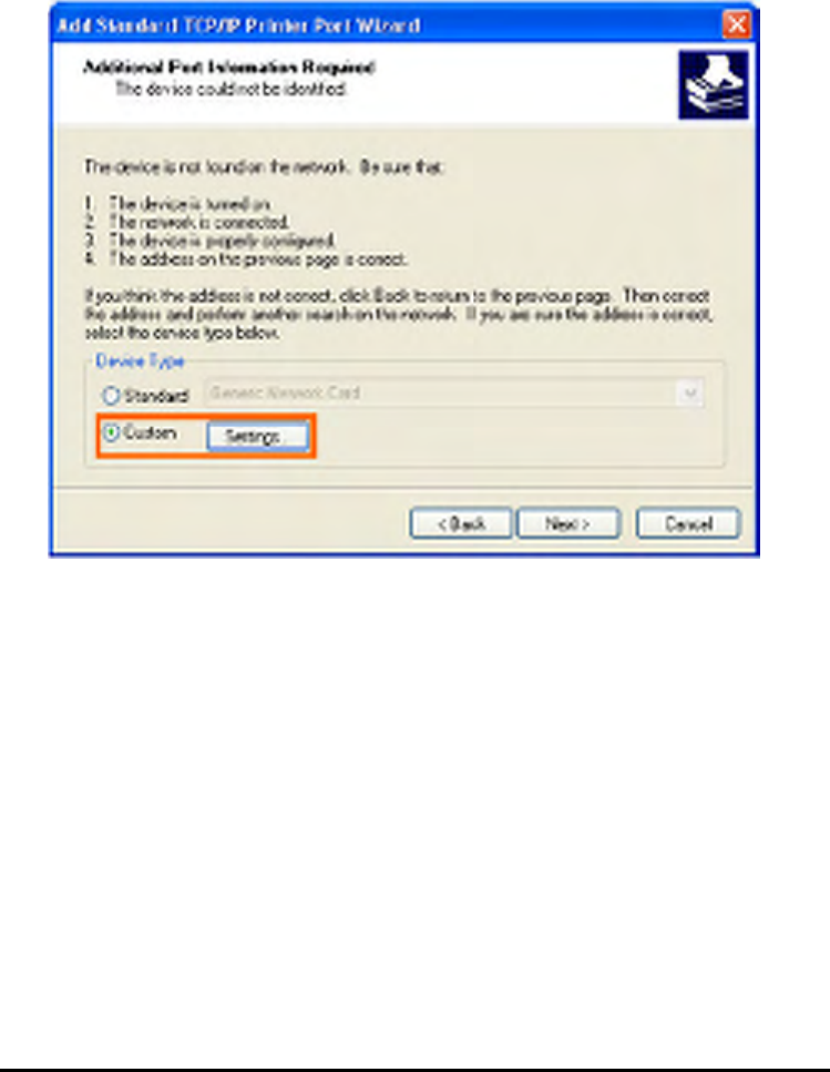
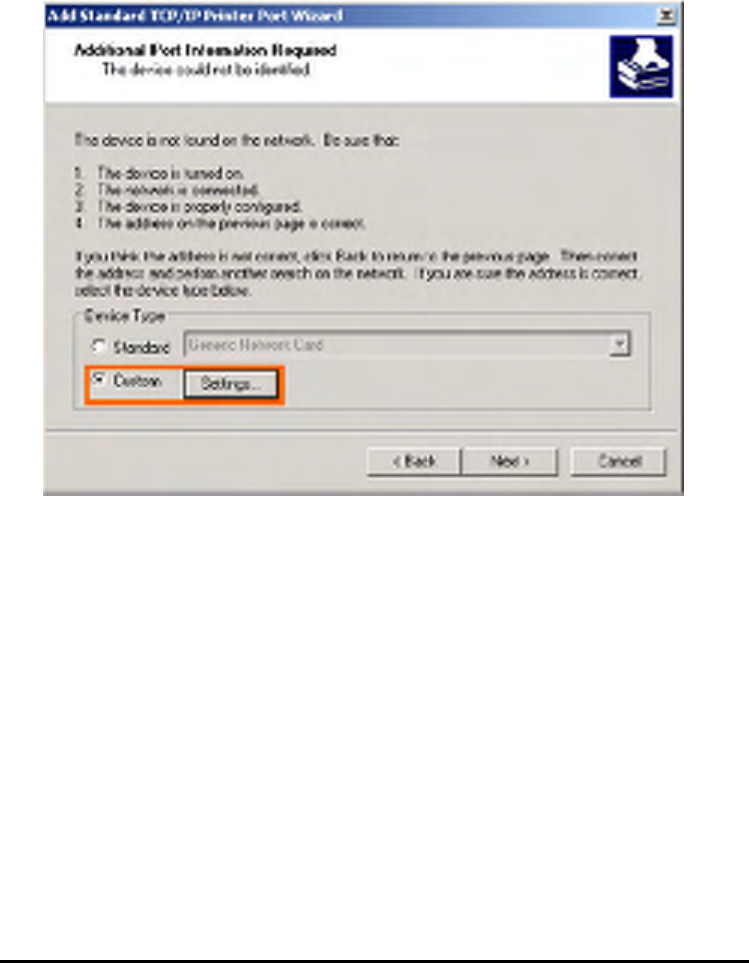
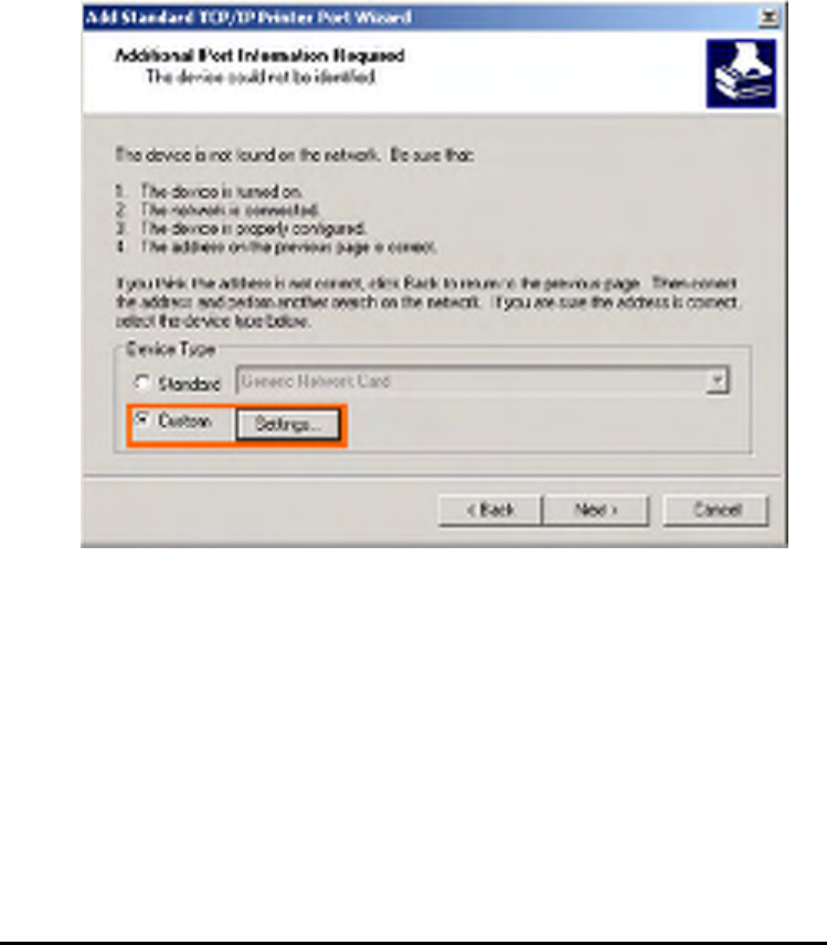
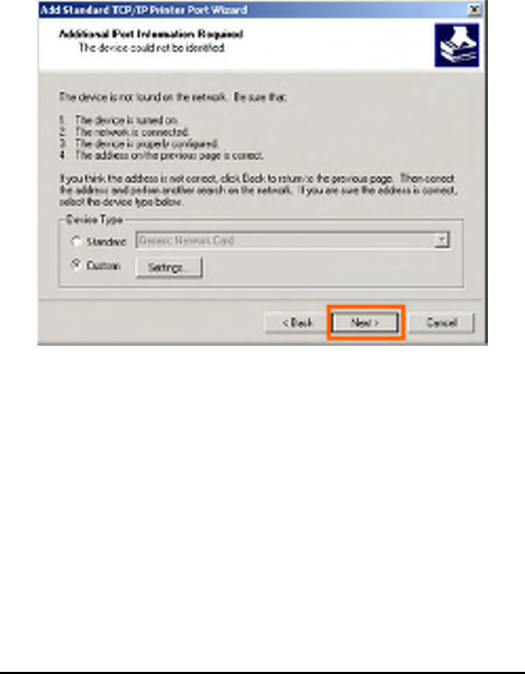
Select Custom and click Settings.
105
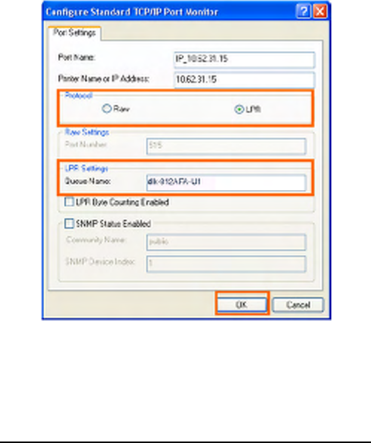
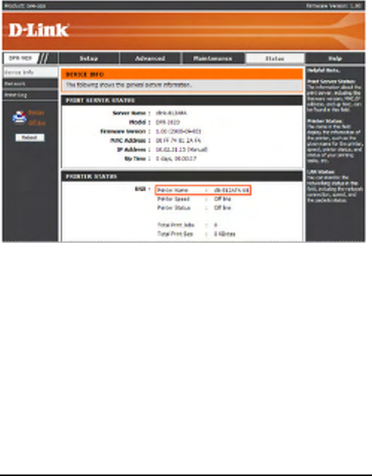
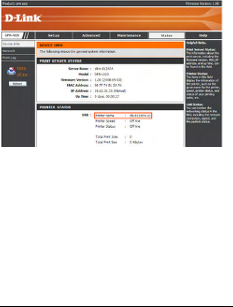
Then the follow screen will shows up, select LPR from the Protocol field.
Then enter the Queue Name, which can be referred from PRINTER STATUS of the
MFP server’s Web configuration, in the LPR Settings field. Click OK.
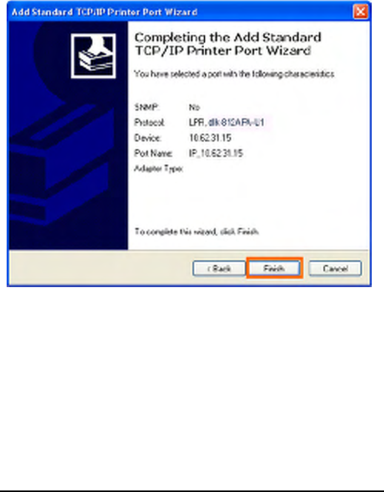
106
107
Click Next.
108
Click Finish.
109
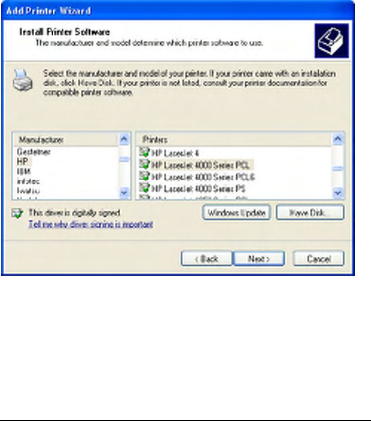
Highlight the printer, as shown. If the desired printer is not on the list, click Have Disk
and insert the printer driver disk that came with your printer to install the printer
drivers.
Click Next
110
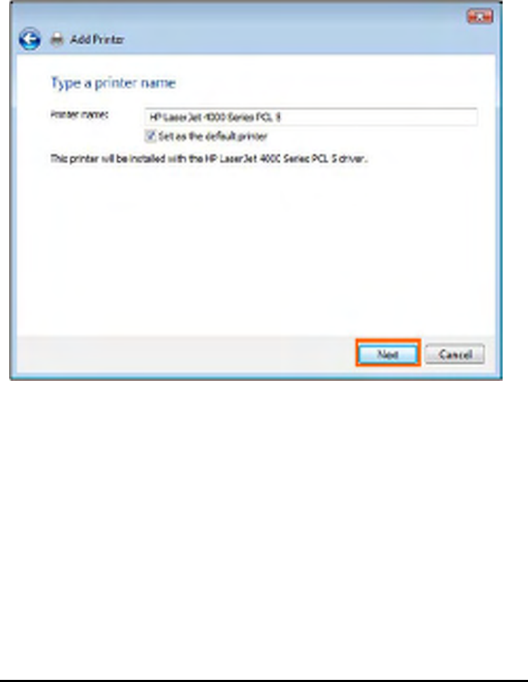
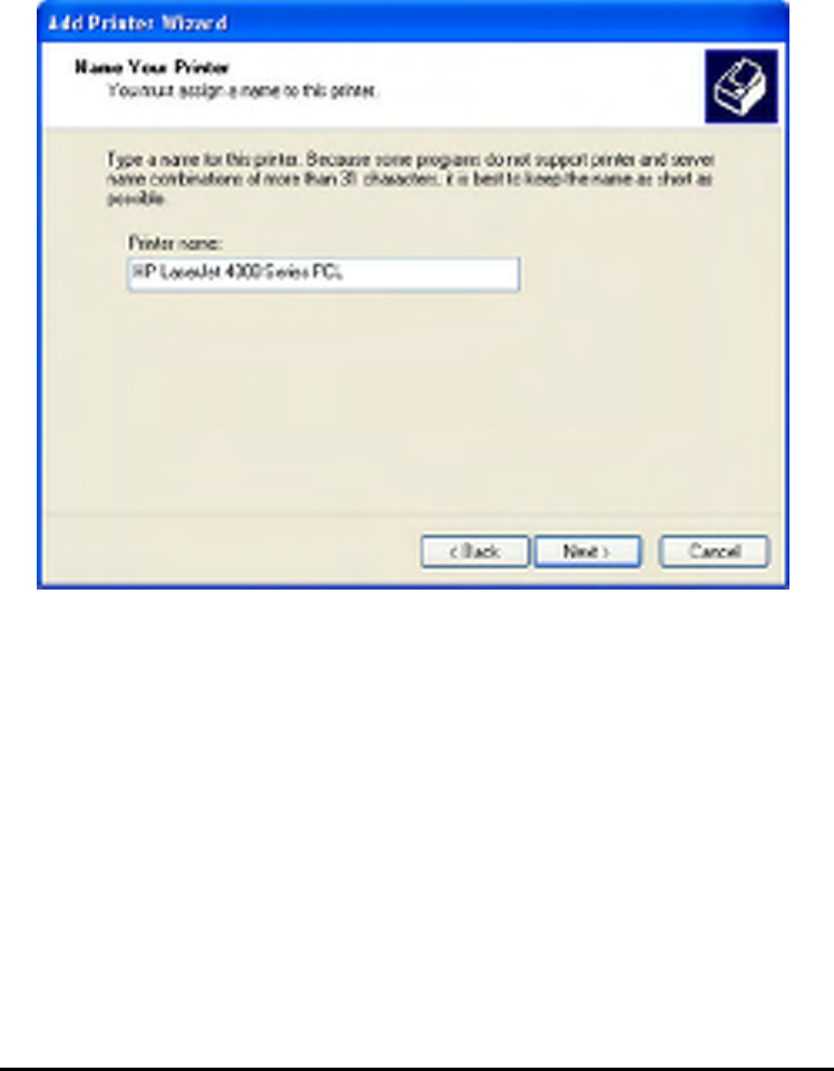
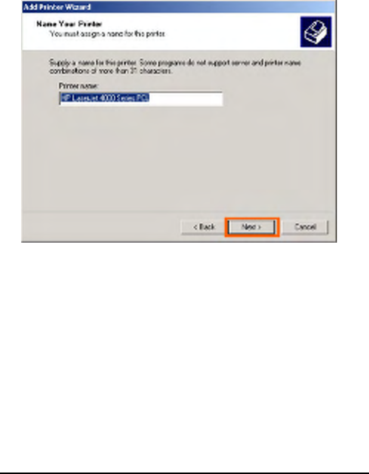
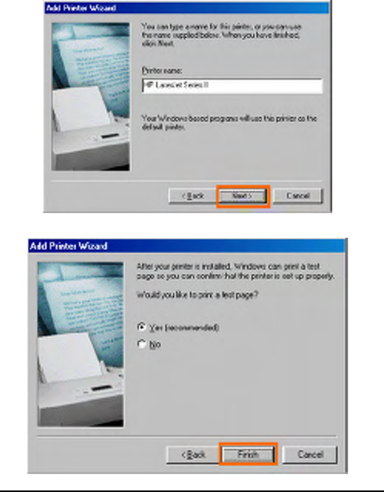
At this screen, you can input a name for the printer, and then click Next
111
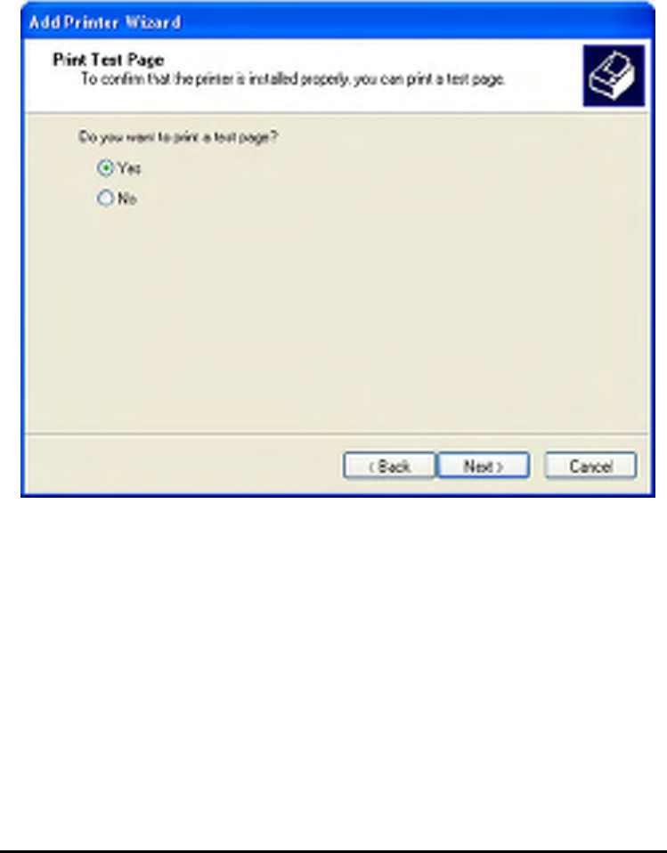
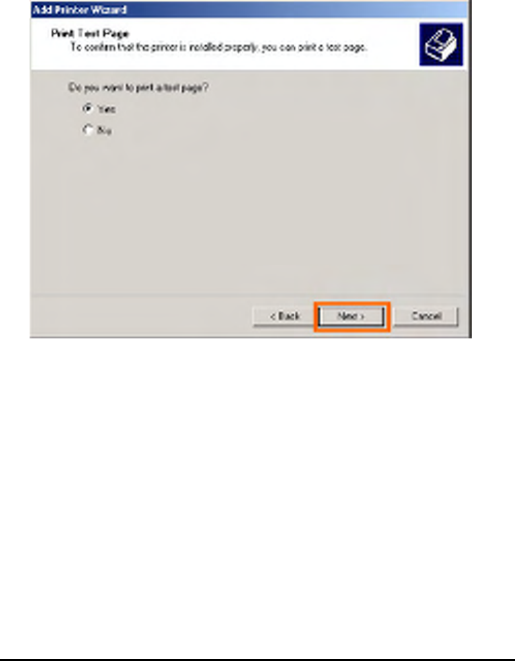
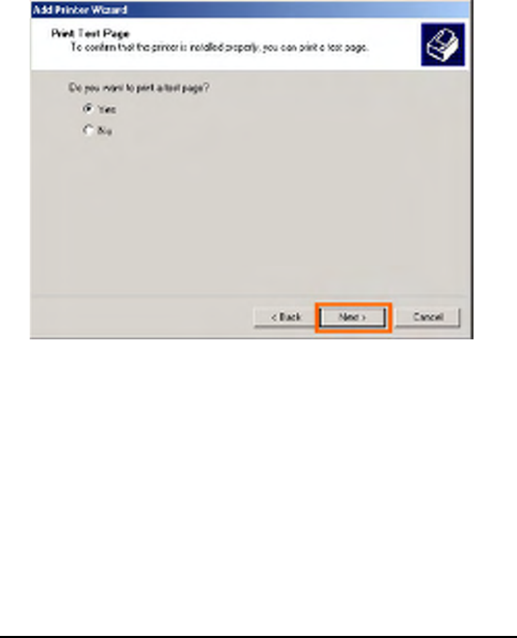
Select Yes to print a test page, click Next.
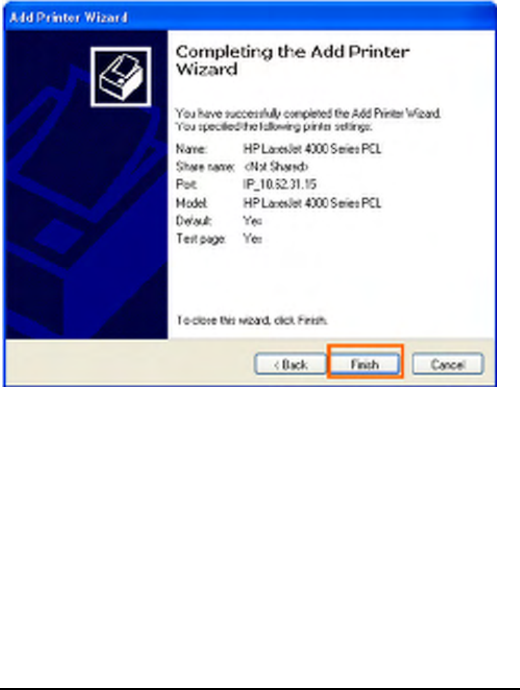
Click Finish. The printer is now ready for printing with Windows XP on your network.
112
113
TCP/IP Printing for Windows 2000
Go to Start => Settings => Printers and Faxes => Add a Printer.
When the following screen shows up, click Next.
114
Select the first option, Local printer attached to this computer, and click Next.
115
Click Next if New Printer Detection page pops up.
Select the second option, Create a new port, and highlight Standard TCP/IP Port
from the pull-down menu. Click Next.
116
Click Next.
117
Type the IP address of the MFP server (e.g. 10.62.31.15 used in this manual), which
can be checked from the PRINTER SERVER STATUS of the MFP server’s Web
configuration, and then the Port Name will automatically be filled in. Click Next
118
Select Custom and click Settings.
119
Then the follow screen will shows up, select LPR from the Protocol field.
Then enter the Queue Name, which can be referred from PRINTER STATUS of the
MFP server’s Web configuration, in the LPR Settings field. Click OK.
120
121
Click Next.
122
Click Finish.
123
Highlight the printer, as shown. If the desired printer is not on the list, click Have Disk
and insert the printer driver disk that came with your printer to install the printer
drivers.
Click Next.
124
At this screen, you can input a name for the printer, and then click Next
125
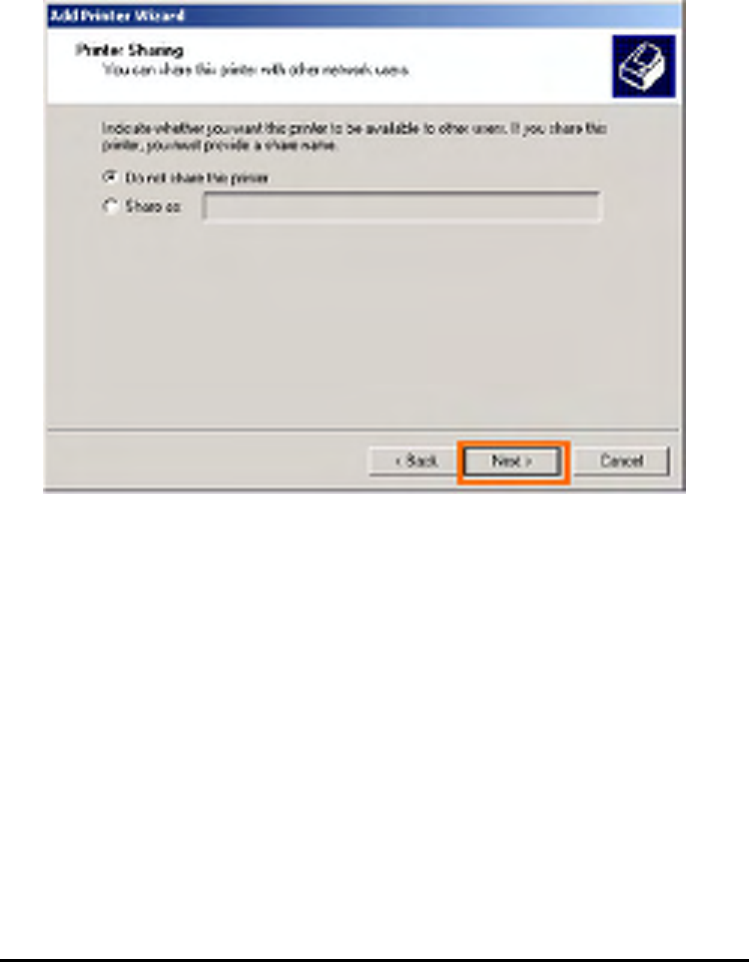
Select the first option, Do not share this printer, and click Next.
126
Select Yes to print a test page, click Next.
127
Click Finish. The printer is now ready for printing with Windows 2000 on your
network.
128
TCP/IP Printingfor Windows 98SE/ME
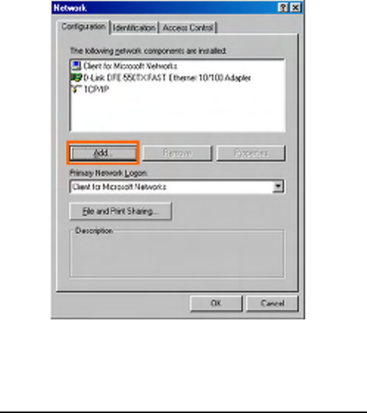
Go to Start => Settings => Control Panel. Double click on Network, and then click
Add.
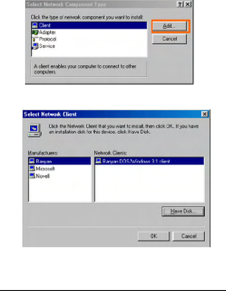
129
Highlight Client and click Add.
At this window, click Have Disk.
130
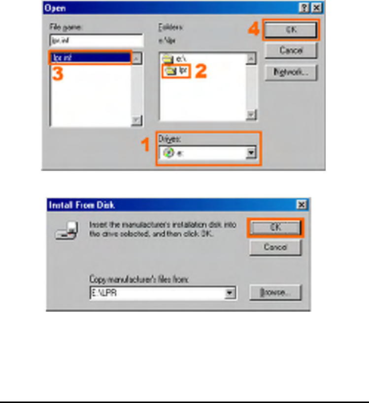
1. Insert the DPP-1061 CD-ROM into your CD-ROM drive. Select the letter
representing the CD-ROM drive on your computer from the pull-down menu.
2. Double-click on the folder lpr.
3. Highlight lpr.inf
4. Click OK.
Click OK to accept the location of the file.
131
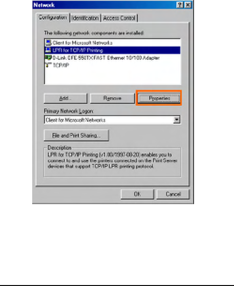
You should now be back to the Network Properties Page. Highlight LPR for TCP/IP
Printing and click Properties.
132
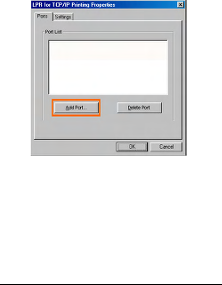
Click Add Port.
133
Type in the IP address and Port Name of the MFP server, which can be referred
from the PRINTER SERVER STATUS and PRINTER STATUS of the MFP server’s
Web configuration, in the corresponding field, and then click OK. (The IP Address
and Port Name here are just for example only.)
134
135
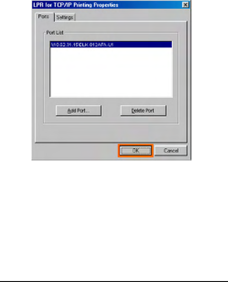
The IP Address and Port Name will be displayed in the following screen. (The IP
Address and Port Name here are just for example only.) Click OK.
136
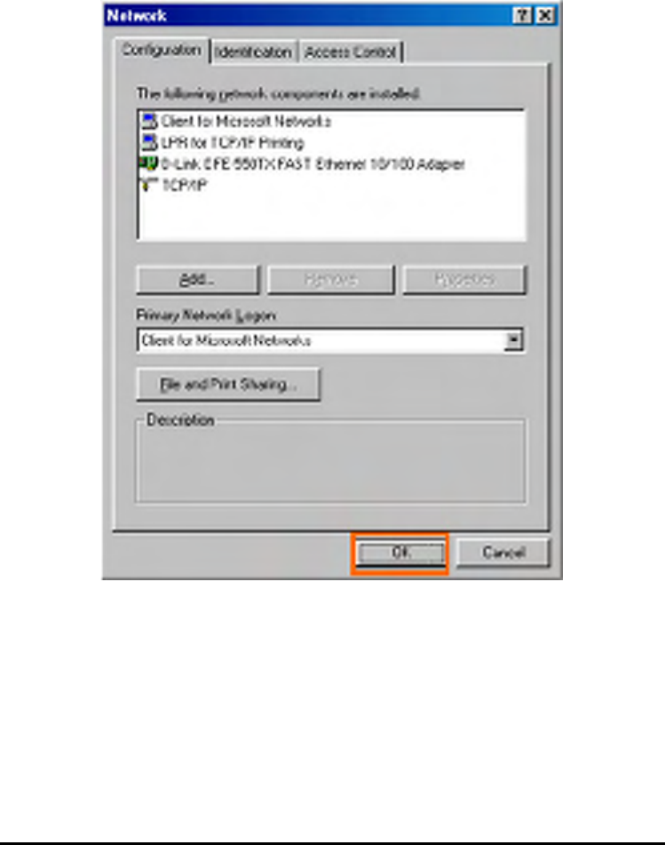
Click OK.
137
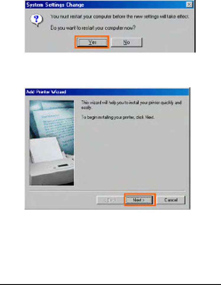
Windows will ask for a restart. Click Yes.
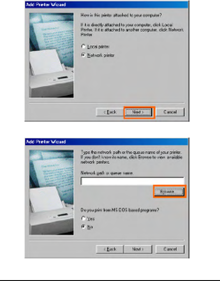
Once your computer has rebooted, click on Start => Settings => Printers => Add
Printer. When the Add Printer Wizard screen appears, click Next.
138
Select Network Printer and click Next.
Type in the path if you know it; otherwise, click Browse.
139
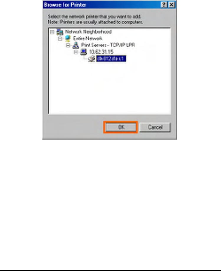
At the following screen, browse for the printer port and highlight the port (e.g.
dlink-1D6FA3 in this manual). Click OK.
140
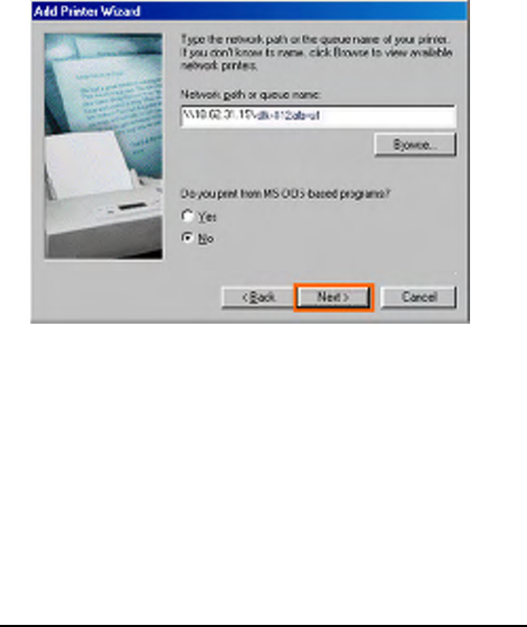
If the network path is not specified, type in the IP Address and Port Name of the
MFP server. Select Yes or No to enable or disable printing from MS-DOS based
programs. Click Next.
141
Highlight the printer, as shown. If the desired printer is not on the list, click Have Disk
and insert the printer driver disk that came with your printer to install the printer
drivers. Click Next.
142
Click Next.
Select Yes to print a test page. Click Finish.
143
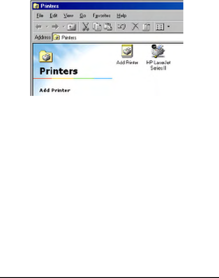
To check whether the printer is installed, go to Start => Settings => Printers.

144
Unix/Linux Printing
Printing Text Files form Unix
Text files on Unix systems contain lines that end with “newline” characters, as
opposed to MS-DOS and Windows-related operating systems that end with a
carriage return followed by a linefeed. Most printers require a carriage
return/linefeed pair at the end of each line, making it necessary for some translation
to be done before Unix text files can be printed on most printers.
For this purpose, you can define two “printers” for the same printer port, one that
prints to the port itself, and one that prints to the port name with _TEXT added to the
name. Files printed to the second port will be translated so that the printer has the
carriage return/linefeed pairs that it needs.
For example, you could define a printer hp5l that prints to port PS-142634-P1,
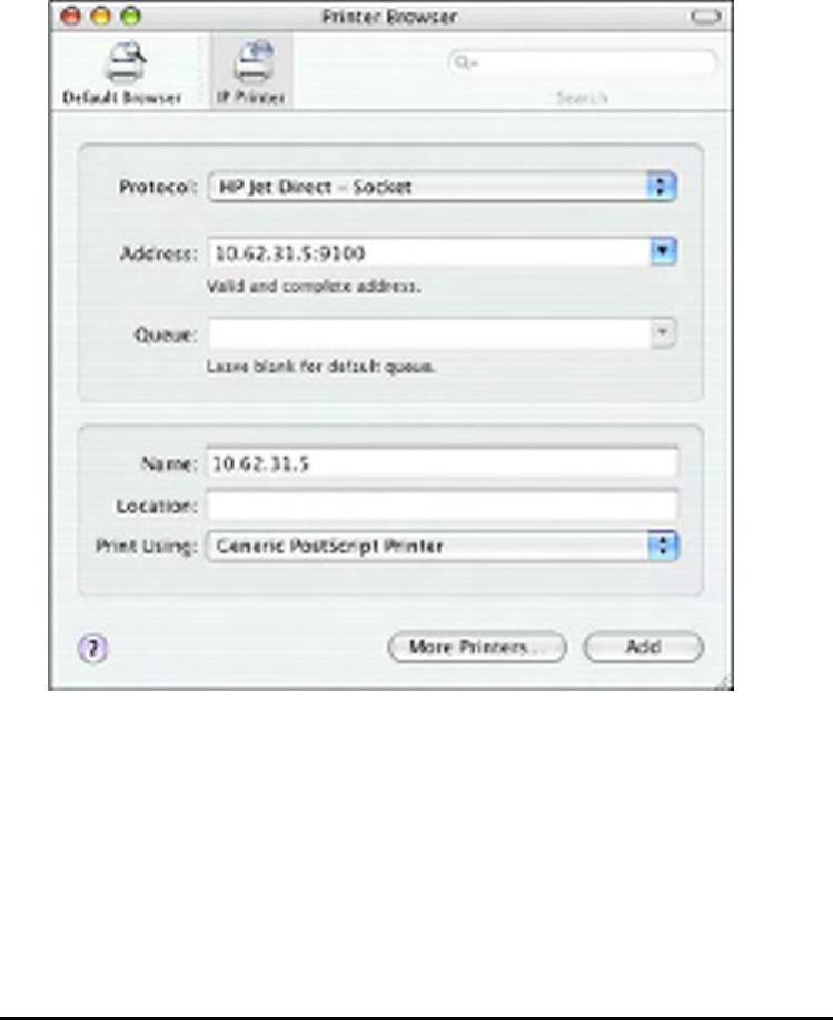
and a printer hp5lt that prints to port PS-142634-P1_TEXT Your graphics files
could then be printed to the hp5l printer, and “raw” text files could be printed to the
hp5lt printer.

145
Printing form BSD Unix Versions
For “flavors” of the Unix operating system derived from or related to the BSD
releases, such as SunOS 4.x, Linux, BSD/OS, FreeBSD, or NetBSD, you can use
the following procedure to enable users to print to a printer connected to your
D-LINK network print server:
1. Log in as the superuser (root).
2. Add an entry for the print server in the host’s /etc/hosts file, giving a hostname
for the print server’s IP address. A line in /etc/hosts contains an IP address
and one or more aliases for the host . For example:
202. 39. 74. 40 ps-142634 ps-142634.dlink.com.tw
If you use DNS (the Domain Naming Services protocol), you can add an address
record entry to your DNS database for the print server.
3. Create a spool directory for the printer:
On SunOS systems, create the directory as a subdirectory of /var/spool,
with the same name as the printer (e.g., /var/spool/hp5l ).
On Linux systems, create the directory as a subdirectory of /user/spool
/lp.
On BSD/OS, FreeBSD, or NetBSD systems, create the directory as
subdirectory of /var/spool.
4. Change the owner and permissions of the directory so that it is owned and
writable by group , using the following commands:

146
chown bin.daemon /var/spool/hp5l
chmod 775 /var/spool/hp5l
5. Add an entry for the printer to /etc/printcap, similar to the following:
hp5l:\
:lp=:sd=/var/spool/hp5l :mx#0:\
:rm=ps-142634:rp=ps-142634-p1:
The meaning of each of the entries is described below. The directory path in the
spool directory entry should match the directory name you created above. If
your entry requires more than one line you can escape the newline with a
backslash.
6. Issue the command
lpc start hp5l
to start a spool daemon for the printer. The printer will now be available for use.
7. Optionally, add another printcap entry (and issue another lpc start command)
for a second printer, using the port_TEXT port. This second printer name can be
used for printing text files.
Entries in /ect/printcap begin with a name for the printer or a list of name,
separated by | (a vertical bar). The entries used above are:
lp= The lp entry is used to specify a local printer device.
Since the printer is a remote printer, this entry should be blank.
145
sd=dir
The location of the printer’s local spool directory.
mx#blocks The limit for print job files in the local spool directory;

147
0 means no limit.
rm=address
The host where the remote printer is located, in this case
the D-Link print server.
rp=printer The name of the printer on the remote host.
For the D-Link print server, the port name should be used.
Note: this entry is case-sensitive.

148
Printing from SCO Unix System V/386
To allow printing to a printer attached to your D-LINK network print server from a
SCO Unix System V/386 host.
1. Login as the superuser (root).
2. Add an entry for the print server in the host’s /etc/hosts file, giving a hostname
for the print server’s IP address. A line in /etc/hosts contains an IP address
and one or more aliases for the host. For example:
202.39.74.40 ps-142634 ps-142634.dlink.com.tw
If you use DNS (the Domain Naming Services protocol), you can add an address
record entry to your DNS database for the print server.
3. Change to the /dev directory, and issue the command
mkdev rlp
4. The script will ask:
Do you want to install or delet remote printing (i/d/q)?
Answer i and press Enter to continue.
5. The script will ask:
Do you want to change the remote printer description file
/etc/printcap (y/n)?
Answer y and press Enter to continue.
6. The script will ask:
Please enter the printer name (q to quit):

149
Enter an alias for the printer on the local machine and press Enter. This name
should be the same as the destination port name.
7. Answer r (remote printer) to the question
Is printer a remote printer or a local printer (r/l)?
8. When prompted with the question:
Please enter the name of the remote host that printer is attached
to:
then enter the address of the D-Link print server. You can use the name you
added to /etc/host in the step above.
9. Confirm that your entries are correct.
Is this correct? (y/n)
10. Answer the question:
Would you like this to be the system default printer? (y/n)
11. When you are done adding remote printers, enter q for the printer name.
12. Answer y to the question
Do you want to start remote daemon now (y/n)?
Once remote printing is set up, you can use the lp command to print jobs to the new
printer. For more information, consult your SCO Unix documentation.

150
Printing from Solaris
To allow printing from a Sun Solaris workstation,
1. Log in as the superuser (root).
2. Add an entry for the print server in the host’s /etc/hosts file, giving a hostname
for the print server’s IP address. A line in /etc/hosts contains an IP address
and one or more aliases for the host . For example:
202.39.74.40 ps-142634 ps-142634.dlink.com.tw
If you use DNS (the Domain Naming Services protocol), you can add an address
record entry to your DNS database for the print server.
3. In OpenWindows, start the admintool program.
4. Click on the Printer Manger icon.
5. From the Edit menu, select Add Print, then Add Access to Remote Printer…
6. Enter values for the fields as follow:
Printer Name This field should contain the name of the printer port you wish to
use. The field is case-sensitive.
Printer Server This field should contain the IP address of the print server, or
the alias name you added in step 2.
Printer Server OS This field should be set to BSD.
7. Confirm the addition.
8. Optionally repeat the addition to add another printer for printing text files,
with_TEXT appended to the port name.
Once you have added the new printer, you can use the lp command to print files to
the printer. Consult your Solaris documentation for details.
151
Printing from Red Hat Linux
Adding a Printer
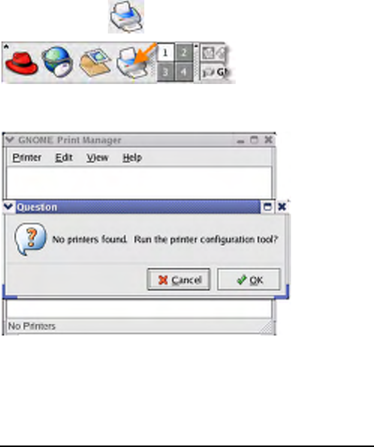
1. Click the printer icon at the bottom of the desktop.
2. Since no printer is set up so far, a prompt appears asking to run the printer
configuration tool.
152
3. Click the OK button in the pop-up dialogue box to open the man Printer
configuration tool menu. Note that to use the Printer configuration tool you must
have root privileges, and to start the application you may also type the command:
“redhat-config-printer”.
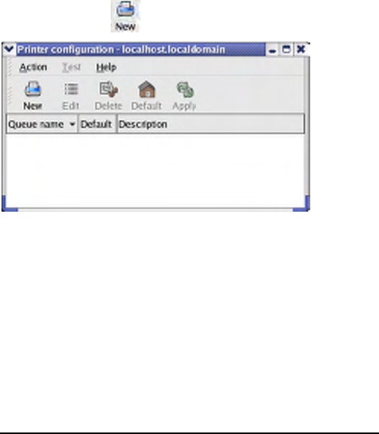
4. Click the New button in the Printer configuration tool menu.
153
Printer Configuration Tool menu
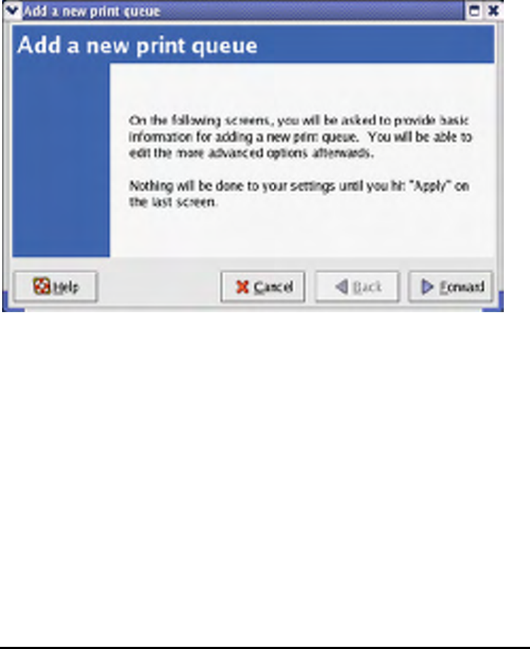
5. The Add a new print queue menu appears, click Forward to continue.
154
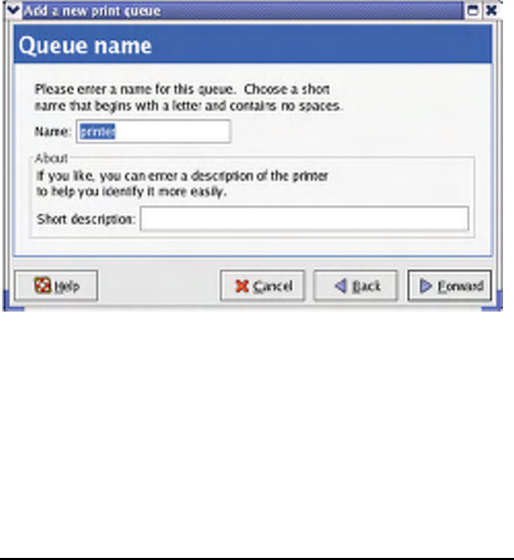
6. Enter a unique name for the printer in the Name text field. The printer name
cannot contain spaces and must begin with a letter. The printer name may contain
letters, numbers, dashes (-), and underscores (_). Optionally, enter a short
description for the printer, which can contain spaces. Then click Forward to enter
Queue type window.
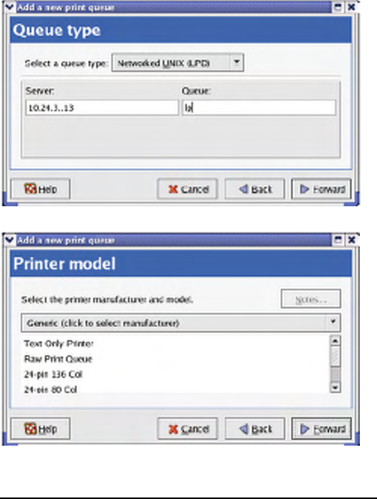
7. Select Networked UNIX (LPD) in the Select a queue type pull down menu, enter
the IP address of the print server to which the printer is attached in Server field, and
type the port name in queue field. Click Forward to select the type of printer.
155
8. Select the printer model.
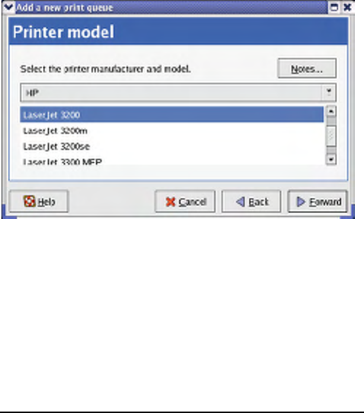
156
If a printer has not been detected automatically, select the model from the list. You
can manually select the name of the printer manufacturer from the Generic (click to
select manufacturer) pull-down menu, and the printer model from the sub-list. Click
Forward to continue.
9. The last step is to confirm your printer configuration. Click Apply button to confirm
or Back button to modify the configuration.
157
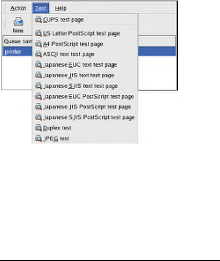
10. Print a test page to make sure the printer is functioning properly. To print a test
page, select the printer from the printer list, then select the appropriate test page
from the Test drop-down menu.
158
Setting up Printing in Mac OS X Tiger(10.4.9)
NOTE: Mac OS printing is supported by Postscript printers only!
With Mac OS X Tiger (10.4), you can use Apple Talk, Bonjour, Internet Printing
Protocol (IPP), Line Printer Daemon (LPD), and HP Jet Direct-Socket printing
through Print Server.
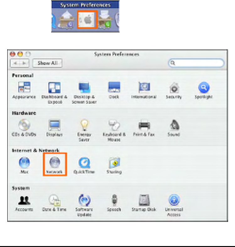
Click on this icon in your Dock to open your System
Preferences window as below.
Click on the Network icon in System Preferences menu to view the menu below.
159
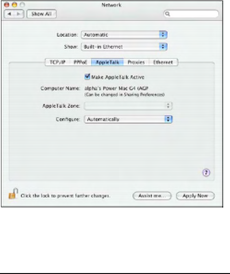
Select the Apple Talk tab in the Network menu. Check to select the Make Apple
Talk Active option. Click on the Apply Now button and close the menu. Apple Talk
is now active on the system. Now a printer can be added.
Adding a Printer
Use the Go menu at the top tool bar and select Applications option and find the
Utilities folder or open the Utilities folder directly in Go menu.
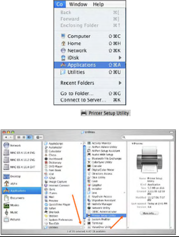
160
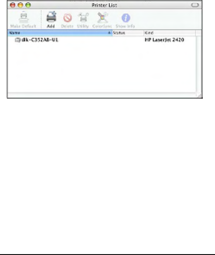
In the Utilities folder, find and select to see the Printer
List dialog window.
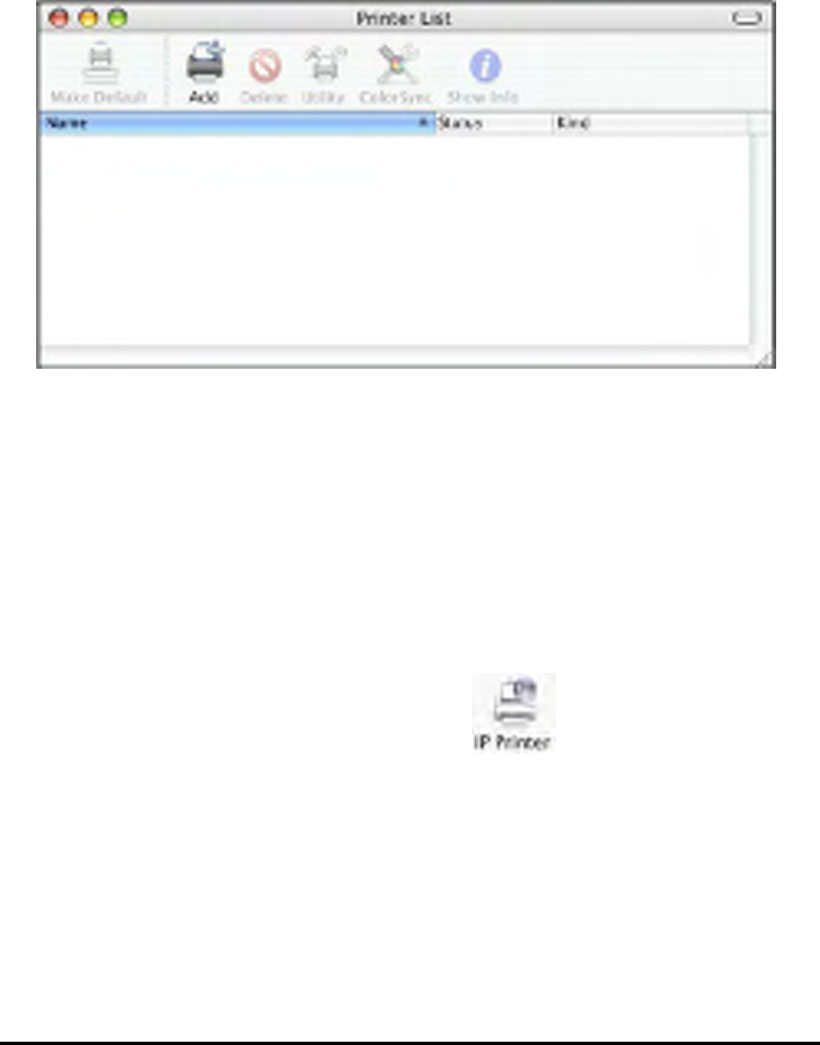
161
Click Add button to open Printer Browser window.
Mac OS X Tiger (10.4) supports five printing protocols:
1. AppleTalk
2. Bonjour
3. Internet Printing Protocol (IPP)
4. Line Printer Daemon (LPD)
5. HP Jet Direct – Socket
To add an Internet Printing Protocol enabled, Line Printer Daemon enabled or HP
Jet Direct – Socket enabled printer, click on the button and follow the
instructions to add an IP Printer beginning on “Adding an IP printer” session.
162
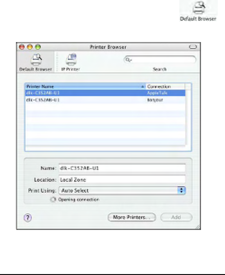
AppleTalk-enabled or Bonjour-enabled Printers
To add an AppleTalk-enabled or Bonjour-enabled printer, click the
button in the Printer Browser menu.
Select the printer model from Printer Name list and Connection type in the Printer
Browser menu. The printer name selected should be the same as that appearing
listed in the Printer Server’s web manager. In the example here, the printer name is
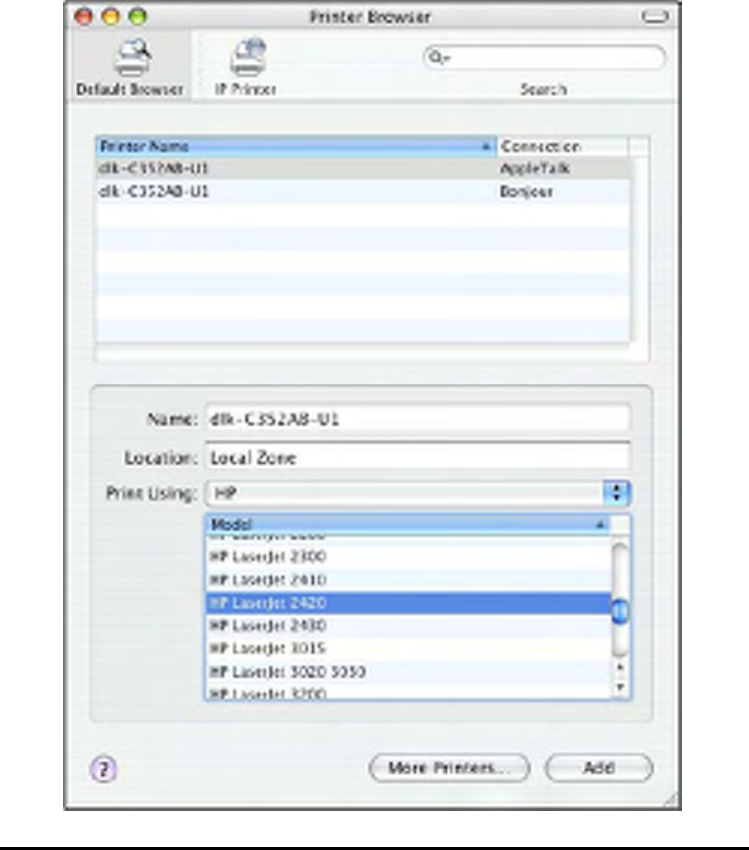
163
dlk-C352AB-U1. By default the Printer Browser will use the Auto Select for Print
Using: to determine what printer configuration to use. This may also be manually
selected in the Print Using drop-down menu by brand and model. Click the Add
button to exit the Printer Browser window and implement the new setting.
164
The printer that has just been added will show up in the Printer List menu, it might
take a few seconds depending on network conditions. When the printer appears
listed it is ready for use. Quit the Printer Setup Utility and start printing.
165
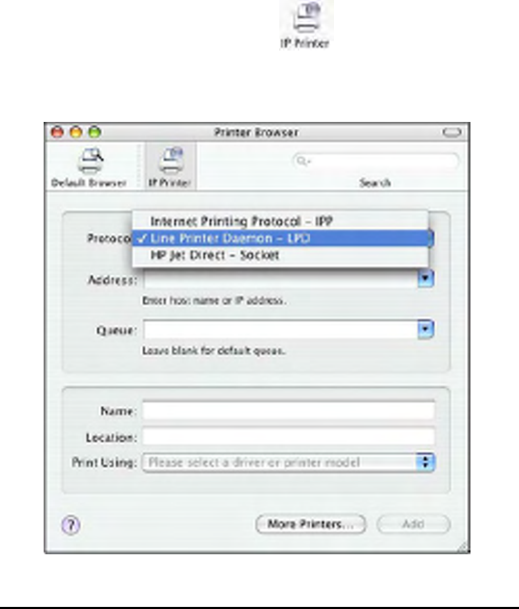
Adding an IP Printer
To add an Internet Printing Protocol enabled, Line Printer Daemon enabled or HP
Jet Direct – Socket enabled printer, click the button in the Printer
Browser window. Select a desired printing protocol from the Protocol drop-down
menu.

166
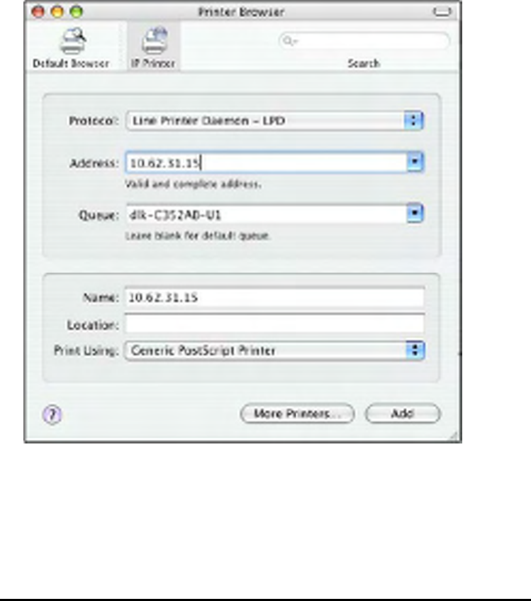
Type the IP Address of the printer. The name will appear in the Name field when the
printer is found. The Printer Browser will indicate that it is verifying the address. If
the printer is found, the Printer Browser will state “Valid and complete address” in
the Address field.
The printer utility is able to detect the printer and may automatically select the
correct printer driver in the Print Using field. Or manually select the printer-maker
from the Print Using drop-down menu, and then select the printer model from the
scroll-down list, or select Generic PostScrip Printer option from the Print Using
drop-down menu if the model is not listed. To implement the setting, click Add
button.
The setup procedures for these three printing protocols (Internet Printing Protocol
(IPP), Line Printer Daemon (LPD), and HP Jet Direct – Socket) are basically the
same. Illustrated examples are include below for the sake of reference.
167
For set up LPD Printing:
1. Enter the IP address of the print server to which the printer is attached in
Address field.
2. Type the port name in the Queue field.
Click Add button after done the section of printer model in the Print Using
drop-down menu.
For set up IPP Printing:
1. Enter the IP address of the print server to which the printer is attached in
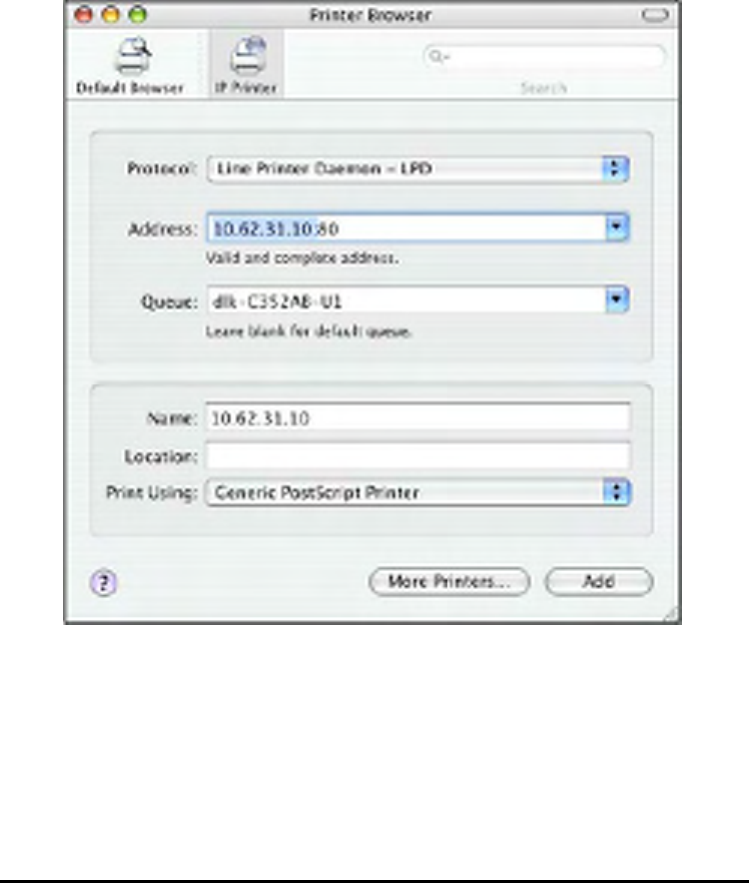
168
Address field. After that, type
“: 80”
or
“: second port”
if print server’s
second port is enabled.
2. Type the port name in the Queue field.
Click Add button after done the section of printer model in the Print Using
drop-down menu.
For set up Socket Printing:
1. Enter the IP address of the print server to which the printer is attached in
Address field. After that, type “: 9100” for port 1, “: 9101” for port 2 or “: 9102”
169
for port 3.
2. Keep the blank in Queue field.
Click Add button after done the section of printer model in the Print Using
drop-down menu.
170
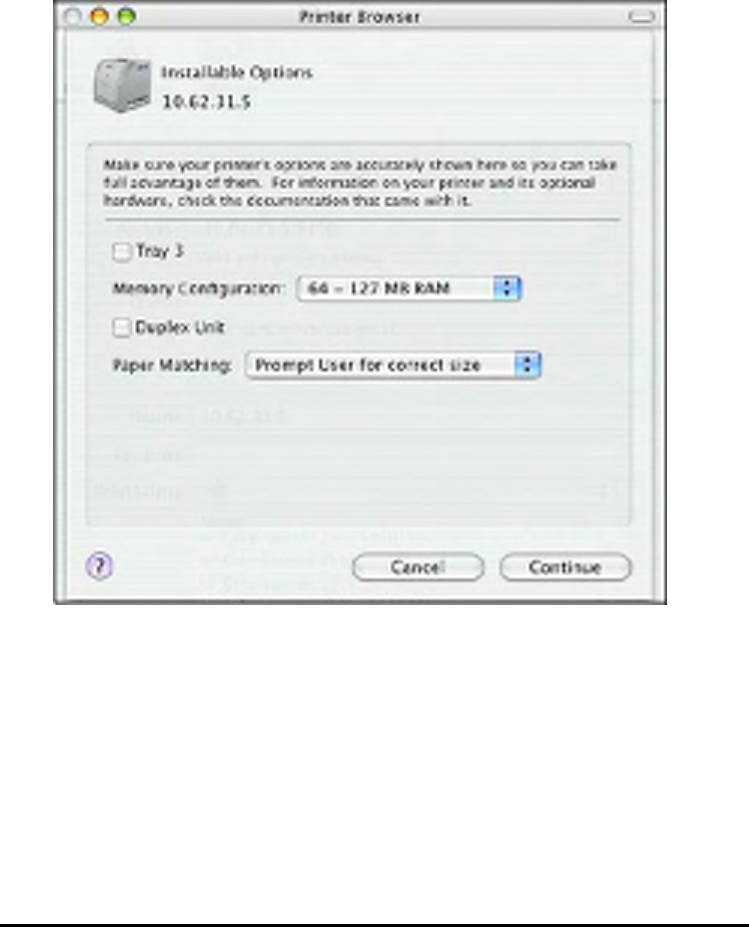
When the Installable Options pop-up window shows up as below, click Continue
button.
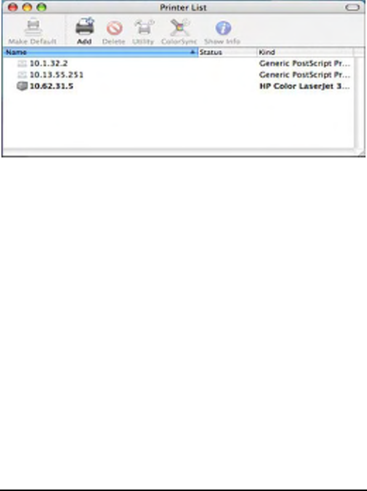
The printer that has just been added will show up in the Printer List menu, it might
take a few seconds depending on network conditions. When the printer appears
listed it is ready for use. Quite the Printer Setup Utility and start printing.
171

172
Setting up AppleTalk Printing in Mac OS 9
: Mac OS printing is supported by Postscript printers only!
The AppleTalk network protocol is used with computers using the MacOS operating
system. It can be used for network communications over standard Ethernet or Fast
Ethernet using the EtherTalk transport, or over a proprietary low-speed LocalTalk
transport.
MFP server can be used for network printing to PostScript printers. You can print
from any MacOS computer connected to your Ethernet network, either directly using
an EtherTalk connection, or indirectly through a LocalTalk-to-EtherTalk router.
: The Chooser name of a printer connected to one of the Print Server‘s
ports is the same as its Port Name. If you are using AppleTalk printing, you
will need to make sure that every Port Name is unique among all of the
network printers in your AppleTalk zone. The Port Names shown in this
manual are examples only.
To set up MFP server so that it can be used for AppleTalk printing:
Make sure the AppleTalk protocol is enabled in your Macintosh.
Make sure the PC’s IP Address must correspond with the Print Server’s IP
Address in the same segment for the two devices to communicate.
Launch the browser and enter print server web interface, select the ADVANCED
tab, click Advanced LAN button and then scroll to the bottom to the AppleTalk
protocol section
If your AppleTalk network is divided into AppleTalk zones, you will have to
specify which zone the Print Server should be in. You should locate the Print Server
in the same zone as most of the users who will be using it. If your network is not
divided into zones, the AppleTalk Zone field should contain a single asterisk (*).
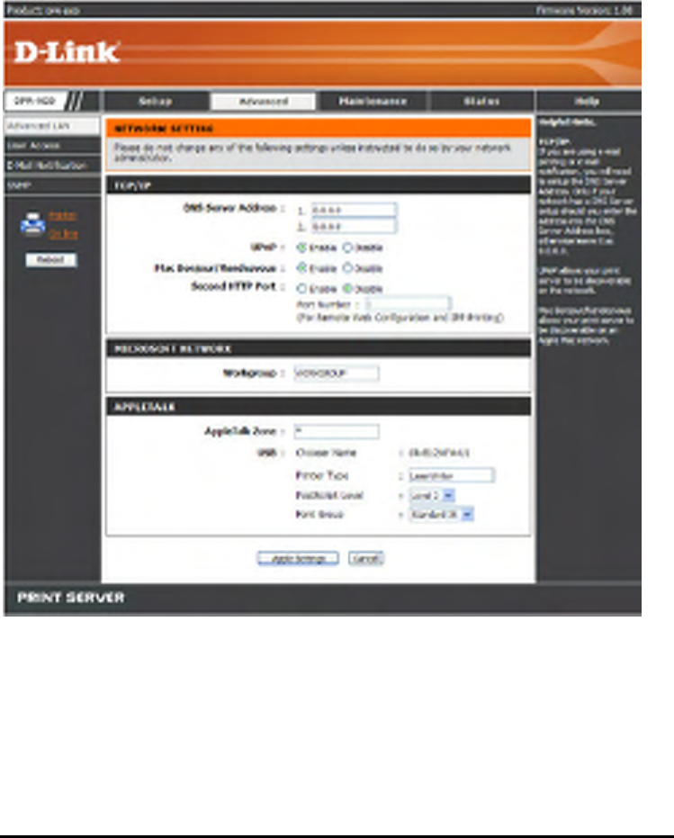
173
For each Printer Port that will be used for AppleTalk printing, you may need to
change the AppleTalk Port Settings in the Advanced LAN screen, shown as below.
AppleTalk
Enter the AppleTalk Zone name in the box. In the following options, enter the related
configuration, such as the printer type.
Chooser Name: Display the print server's port name.
Printer Type: Enter the printer's type in this box.
PostScript Level: Select from the pull-down menu (Level 1 or Level 2).
174
Font Group: Select from the pull-down menu.
The exact procedure for selecting a PostScript printer connected to MFP server may
vary slightly, depending on what printer driver version you are using. The procedure
described below assumes you are using the LaserWriter 8.
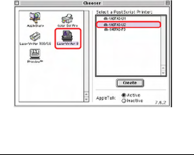
To choose a printer connected to MFP server as your MacOS workstation‘s default
printer, open the Chooser by selecting Chooser from the Apple menu. Select the
LaserWriter 8 icon on the left. Make sure that AppleTalk is set to Active.
A list of all networked PostScript printers will be displayed as follow.
Double-click the name of the Printer Port you wish to use. The Printer Ports shown
are examples only.
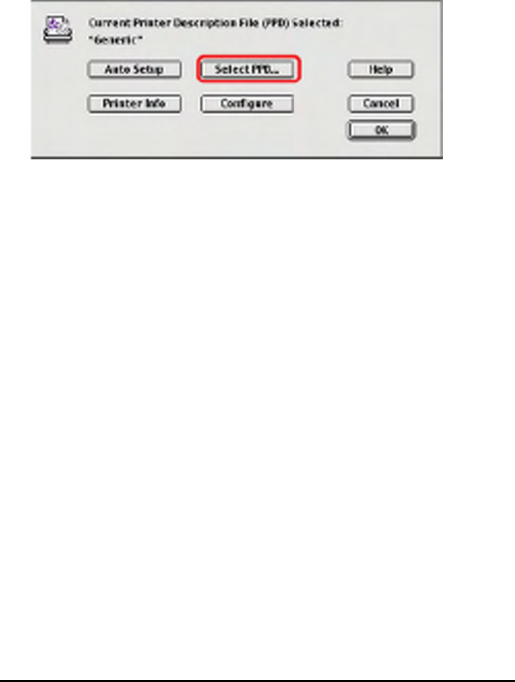
If you have not previously set this printer as the default, your computer will prompt
you for a PostScript Printer Description file. Choose Select PPD.
175
Select the appropriate printer description file for your printer.
Click Open. (If your printer is not listed, click Generic to use a generic printer
description.)
If you wish to access this setting in the future, you can use the Setup button in the
Chooser window.
The selected printer will become your computer‘s default printer. You may need to
choose Page Setup in any applications you have open.

176
Technical Specifications
Printer Connection
Printer Port: USB 2.0
Bi-directional Communication: Hewlett-Packard PJL (Printer Job Language)
standard for bi-directional communication.
Network Connection
Network Standards: 100Base-TX Fast Ethernet
Network Data Transfer Rate: 10/100 Mbps (megabits per second)
Network Connector: RJ-45
Network Protocols
Ethernet Frame Types: 802.2, 802.3, Ethernet II, SNAP (auto-switching)
Transport Protocols: TCP/IP, NetBEUI, AppleTalk/EtherTalk, LPR,SMB
TCP/IP Protocols Supported: BOOTP, SNMP, FTP, LPD, RARP, DHCP, IPP
Management and Diagnostics
Standard: SNMP
MIBs: MIB-II (RFC 1213)
Diagnostic LED Indicators: Power, Link/Act, USB
Environmental and Physical
Power Supply: External power supply providing 5V, 2.5A DC
Dimensions: 58.1(W) x 26.5(H) x 90(D)mm
Weight: approx. 10.3 oz. (292g)
Operating Temperature: 32 to122°F (0 to 50°C)
Storage Temperature: -13 to 131°F (-25 to 55°C)
Humidity: 5% to 95% non-condensing
Emissions: FCC Class B, CE Class B, VCCI Class B
180

177
Contacting Technical Support
181
Warranty and Registration
Subject to the terms and conditions set forth herein, D-Link Systems, Inc. (—D-Link“) provides this
Limited warranty for its product only to the person or entity that originally purchased the product from:
D-Link or its authorized reseller or distributor and
Products purchased and delivered within the fifty states of the United States, the District of
Columbia, U.S. Possessions or Protectorates, U.S. Military Installations, addresses with an
APO or FPO.
Limited Warranty: D-Link warrants that the hardware portion of the D-Link products described below will
be free from material defects in workmanship and materials from the date of original retail purchase of the
product, for the period set forth below applicable to the product type (—Warranty Period“), except as
otherwise stated herein.
1-Year Limited Warranty for the Product(s) is defined as follows:
Hardware (excluding power supplies and fans) One (1) Year
Power Supplies and Fans One (1) Year
Spare parts and spare kits ninety (90) days.
D-Link‘s sole obligation shall be to repair or replace the defective Hardware during the Warranty Period at
no charge to the original owner or to refund at D-Link‘s sole discretion. Such repair or replacement will be
rendered by D-Link at an Authorized D-Link Service Office. The replacement Hardware need not be new
or have an identical make, model or part. D-Link may in its sole discretion replace the defective Hardware
(or any part thereof) with any reconditioned product that D-Link reasonably determines is substantially
equivalent (or superior) in all material respects to the defective Hardware. Repaired or replacement
Hardware will be warranted for the remainder of the original Warranty Period from the date of original
retail purchase. If a material defect is incapable of correction, or if D-Link determines in its sole discretion
that it is not practical to repair or replace the defective Hardware, the price paid by the original purchaser

178
for the defective Hardware will be refunded by D-Link upon return to D-Link of the defective Hardware. All
Hardware (or part thereof) that is replaced by D-Link, or for which the purchase price is refunded, shall
become the property of D-Link upon replacement or refund.
Limited Software Warranty: D-Link warrants that the software portion of the product (—Software“) will
substantially conform to D-Link‘s then current functional specifications for the Software, as set forth in the
applicable documentation, from the date of original retail purchase of the Software for a period of ninety
(90)days (—Warranty Period“), provided that the Software is properly installed on approved hardware and
operated as contemplated in its documentation. D-Link further warrants that, during the Warranty Period,
the magnetic media on which D-Link delivers the Software will be free of physical defects. D-Link‘s sole
obligation shall be to replace the non-conforming Software (or defective media) with software that
substantially conforms to D-Link‘s functional specifications for the Software or to refund at D-Link‘s sole
discretion. Except as otherwise agreed by D-Link in writing, the replacement Software is provided only to
the original licensee, and is subject to the terms and conditions of the license granted by D-Link for the
Software. Software will be warranted for the remainder of the original Warranty Period from the date or
original retail purchase. If a material non-conformance is incapable of correction, or if D-Link determines
in its sole discretion that it is not practical to replace the non-conforming Software, the price paid by the
original licensee for the non-conforming Software will be refunded by D-Link; provided that the
non-conforming Software (and all copies thereof) is first returned to D-Link. The license granted
respecting any Software for which a refund is given automatically terminates.
Non-Applicability of Warranty: The Limited Warranty provided hereunder for hardware and software of
D-Link‘s products will not be applied to and does not cover any refurbished product and any product
182
purchased through the inventory clearance or liquidation sale or other sales in which D-Link, the sellers,
or the liquidators expressly disclaim their warranty obligation pertaining to the product and in that case,
the product is being sold —As-Is“ without any warranty whatsoever including, without limitation, the
Limited Warranty as described herein, notwithstanding anything stated herein to the contrary.
Submitting A Claim: The customer shall return the product to the original purchase point based on its
return policy. In case the return policy period has expired and the product is within warranty, the

179
customer shall submit a claim to D-Link as outlined below:
The customer must submit with the product as part of the claim a written description of the
Hardware defect or Software nonconformance in sufficient detail to allow D-Link to confirm the
same.
The original product owner must obtain a Return Material Authorization (—RMA“) number
from the Authorized D-Link Service Office and, if requested, provide written proof of purchase
of the product (such as a copy of the dated purchase invoice for the product) before the
warranty service is provided.
After an RMA number is issued, the defective product must be packaged securely in the
original or other suitable shipping package to ensure that it will not be damaged in transit, and
the RMA number must be prominently marked on the outside of the package. Do not include
any manuals or accessories in the shipping package. D-Link will only replace the defective
portion of the Product and will not ship back any accessories.
The customer is responsible for all in-bound shipping charges to D-Link. No Cash on
Delivery (—COD“) is allowed. Products sent COD will either be rejected by D-Link or become
the property of D-Link. Products shall be fully insured by the customer and shipped to D-Link
Systems, Inc., 53 Discovery Drive, Irvine, CA 92618. D-Link will not be held responsible for any
packages that are lost in transit to D-Link. The repaired or replaced packages will be shipped to
the customer via UPS Ground or any common carrier selected by D-Link, with shipping
charges prepaid. Expedited shipping is available if shipping charges are prepaid by the
customer and upon request.
D-Link may reject or return any product that is not packaged and shipped in strict compliance with the
foregoing requirements, or for which an RMA number is not visible from the outside of the package. The
product owner agrees to pay D-Link‘s reasonable handling and return shipping charges for any product
that is not packaged and shipped in accordance with the foregoing requirements, or that is determined by
D-Link not to be defective or non-conforming.
What Is Not Covered: This limited warranty provided by D-Link does not cover: Products, if in D-Link‘s
judgment, have been subjected to abuse, accident, alteration, modification, tampering, negligence,

180
misuse, faulty installation, lack of reasonable care, repair or service in any way that is not contemplated in
the documentation for the product, or if the model or serial number has been altered, tampered with,
defaced or removed; Initial installation, installation and removal of the product for repair, and shipping
costs; Operational adjustments covered in the operating manual for the product, and normal
maintenance;
Damage that occurs in shipment, due to act of God, failures due to power surge, and cosmetic damage;
Any hardware, software, firmware or other products or services provided by anyone other than D-Link;
Products that have been purchased from inventory clearance or liquidation sales or other sales in which
D-Link, the sellers, or the liquidators expressly disclaim their warranty obligation pertaining to the product.
Repair by anyone other than D-Link or an Authorized D-Link Service Office will void this Warranty.
Disclaimer of Other Warranties: EXCEPT FOR THE LIMITED WARRANTY SPECIFIED HEREIN,
THEPRODUCT IS PROVIDED —AS-IS“ WITHOUT ANY WARRANTY OF ANY KIND WHATSOEVER
INCLUDING, WITHOUT LIMITATION, ANY WARRANTY OF MERCHANTABILITY, FITNESS FOR A
PARTICULAR PURPOSEAND NON-INFRINGEMENT. IF ANY IMPLIED WARRANTY CANNOT BE
DISCLAIMED IN ANYTERRITORY WHERE A PRODUCT IS SOLD, THE DURATION OF SUCH
IMPLIED WARRANTY SHALL BE LIMITED TO NINETY (90) DAYS. EXCEPTAS EXPRESSLY
183
COVERED UNDER THE LIMITED WARRANTY PROVIDED HEREIN, THE ENTIRERISK AS TOTHE
QUALITY, SELECTION AND PERFORMANCE OF THE PRODUCT IS WITH THE PURCHASER OFTHE
PRODUCT.
Limitation of Liability: TO THE MAXIMUM EXTENT PERMITTED BY LAW, D-LINK IS NOT LIABLE
UNDERANY CONTRACT, NEGLIGENCE, STRICT LIABILITY OR OTHER LEGAL OR EQUITABLE
THEORY FOR ANYLOSS OF USE OF THE PRODUCT, INCONVENIENCE OR DAMAGES OF ANY
CHARACTER, WHETHER DIRECT, SPECIAL, INCIDENTAL OR CONSEQUENTIAL (INCLUDING, BUT
NOT LIMITED TO, DAMAGES FOR LOSS OFGOODWILL, LOSS OF REVENUE OR PROFIT, WORK
STOPPAGE, COMPUTER FAILURE OR MALFUNCTION, FAILURE OF OTHER EQUIPMENT OR
COMPUTER PROGRAMS TO WHICH D-LINK‘S PRODUCT IS CONNECTEDWITH, LOSS OF
INFORMATION OR DATA CONTAINED IN, STORED ON, OR INTEGRATED WITH ANY

181
PRODUCTRETURNED TO D-LINK FOR WARRANTY SERVICE) RESULTING FROM THE USE OF
THE PRODUCT, RELATINGTO WARRANTYSERVICE, OR ARISING OUT OFANY BREACH OF THIS
LIMITED WARRANTY, EVEN IF D-LINKHAS BEEN ADVISED OF THE POSSIBILITY OF SUCH
DAMAGES. THE SOLE REMEDY FOR A BREACH OF THE FOREGOING LIMITED WARRANTY IS
REPAIR, REPLACEMENT OR REFUND OF THE DEFECTIVE OR NON-CONFORMING PRODUCT.
THE MAXIMUM LIABILITY OF D-LINK UNDER THIS WARRANTY IS LIMITED TO THE PURCHASE
PRICE OF THE PRODUCT COVERED BYTHE WARRANTY.THE FOREGOING EXPRESS WRITTEN
WARRANTIES AND REMEDIES ARE EXCLUSIVE AND ARE IN LIEU OF ANY OTHER WARRANTIES
OR REMEDIES, EXPRESS, IMPLIED OR STATUTORY.
Governing Law: This Limited Warranty shall be governed by the laws of the State of California. Some
states do not allow exclusion or limitation of incidental or consequential damages, or limitations on how
long an implied warranty lasts, so the foregoing limitations and exclusions may not apply. This limited
warranty provides specific legal rights and the product owner may also have other rights which vary from
state to state.
Trademarks: D-Link is a registered trademark of D-Link Systems, Inc. Other trademarks or registered
trademarks are the property of their respective manufacturers or owners.
Copyright Statement: No part of this publication or documentation accompanying this Product may be
reproduced in any form or by any means or used to make any derivative such as translation,
transformation, or adaptation without permission from D-Link Corporation/D-Link Systems, Inc., as
stipulated by the United States Copyright Act of 1976. Contents are subject to change without prior
notice. Copyright
©
2002 by D-Link Corporation/ D-Link Systems, Inc. All rights reserved.
CE Mark Warning: This is a Class B product. In a domestic environment, this product may cause radio
interference, in which case the user may be required to take adequate measures.
FCC Statement: This equipment has been tested and found to comply with the limits for a Class B digital
device, pursuant to part 15 of the FCC Rules. These limits are designed to provide reasonable protection
against harmful interference in a residential installation. This equipment generates, uses, and can radiate

182
radiofrequency energy and, if not installed and used in accordance with the instructions, may cause
harmful interference to radio communication. However, there is no guarantee that interference will not
occur in a particular installation. If this equipment does cause harmful interference to radio or television
reception, which can be determined by turning the equipment off and on, the user is encouraged to try to
correct the interference by one or more of the following measures:
Reorient or relocate the receiving antenna.
Increase the separation between the equipment and receiver.
Connect the equipment into an outlet on a circuit different from that to
which the receiver is connected.
Consult the dealer or an experienced radio/TV technician for help.
FCC Caution: Any changes or modifications not expressly approved by the party responsible for
184
compliance could void the user‘s authority to operate this equipment.
This device complies with Part 15 of the FCC Rules. Operation is subject to the following two conditions:
(1) This device may not cause harmful interference, and (2) this device must accept any interference
received, including interference that may cause undesired operation.
IMPORTANT NOTE:
FCC Radiation Exposure Statement:
This equipment complies with FCC radiation exposure limits set forth for an uncontrolled environment.
This equipment should be installed and operated with a minimum distance of about 8 inches (20 cm)
between the radiator and your body.
This transmitter must not be co-located or operated in conjunction with any other antenna or transmitter.
REMARK
IEEE 802.11b or 802.11g operation of this product in the U.S.A. is firmware-limited to channels 1 through 11.
REMARK
IEEE 802.11b or 802.11g operation of this product in the Canada is firmware-limited to channels 1 through 11.
REMARK
IEEE 802.11b or 802.11g operation of this product in the U.S.A. is firmware-limited to channels 1 through 11.
REMARK
IEEE 802.11b or 802.11g operation of this product in the Canada is firmware-limited to channels 1 through 11.
REMARK
IEEE 802.11b or 802.11g operation of this product in the U.S.A. is firmware-limited to channels 1 through 11.
REMARK
IEEE 802.11b or 802.11g operation of this product in the Canada is firmware-limited to channels 1 through 11.
“Operation is subject to the following two conditions:(1) this device may not cause
interference, and (2) this device must accept any interference, including interference
that may cause undesired operation of the device.”
“Operation is subject to the following two conditions:(1) this device may not cause
interference, and (2) this device must accept any interference, including interference
that may cause undesired operation of the device.”
“Operation is subject to the following two conditions:(1) this device may not cause
interference, and (2) this device must accept any interference, including interference
that may cause undesired operation of the device.”
REMARK
IEEE 802.11b or 802.11g operation of this product in the U.S.A. is firmware-limited to channels 1 through 11.
REMARK
IEEE 802.11b or 802.11g operation of this product in the Canada is firmware-limited to channels 1 through 11.
“Operation is subject to the following two conditions:(1) this device may not cause interference, and (2) this
device must accept any interference, including interference that may cause undesired operation of the device.”

NCC Warning Statement
Article 12
Without permission, any company, firm or user shall not alter the frequency,
increase the power, or change the characteristics and functions of the original
design of the certified lower power frequency electric machinery.
Article 14
The application of low power frequency electric machineries shall not affect the
navigation safety nor interfere a legal communication, if an interference is
found, the service will be suspended until improvement is made and the
interference no longer exists.
183