D Link SR150NA1 802.11 bgn Service Router User Manual
D Link Corporation 802.11 bgn Service Router
UserManual.wiki
>
D Link
>
SR150NA1 User Manual
User Manual
Navigation menu
Upload a User Manual
Namespaces
Wiki Guide
HTML
PDF
Info
Views
User Manual
Discussion / Help
Navigation
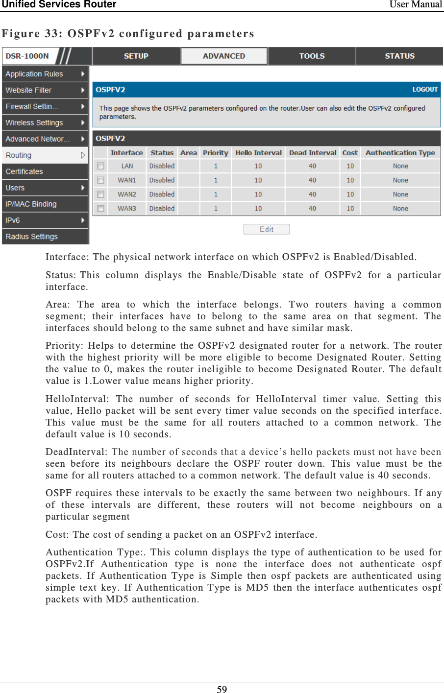
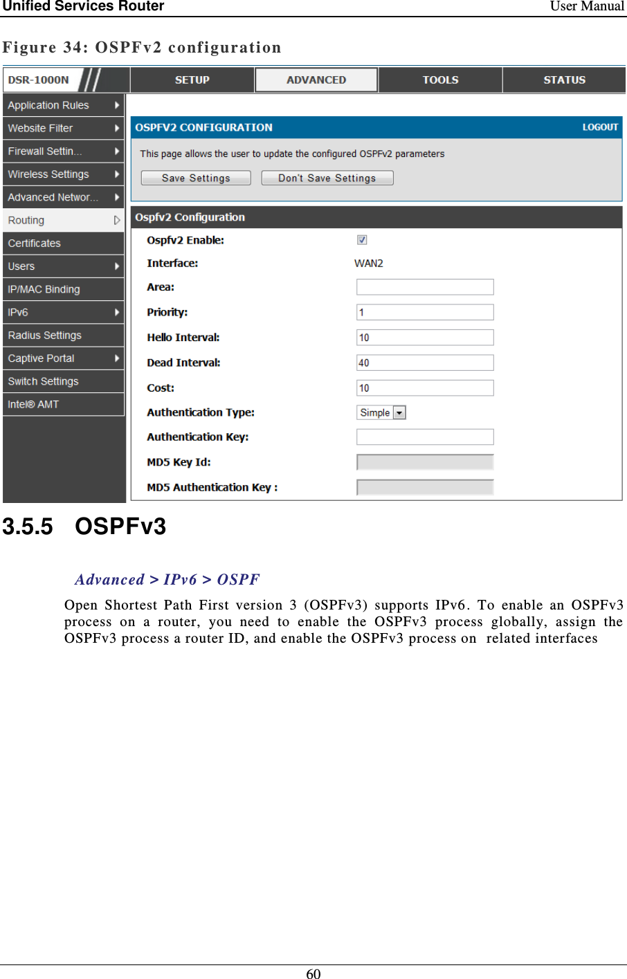
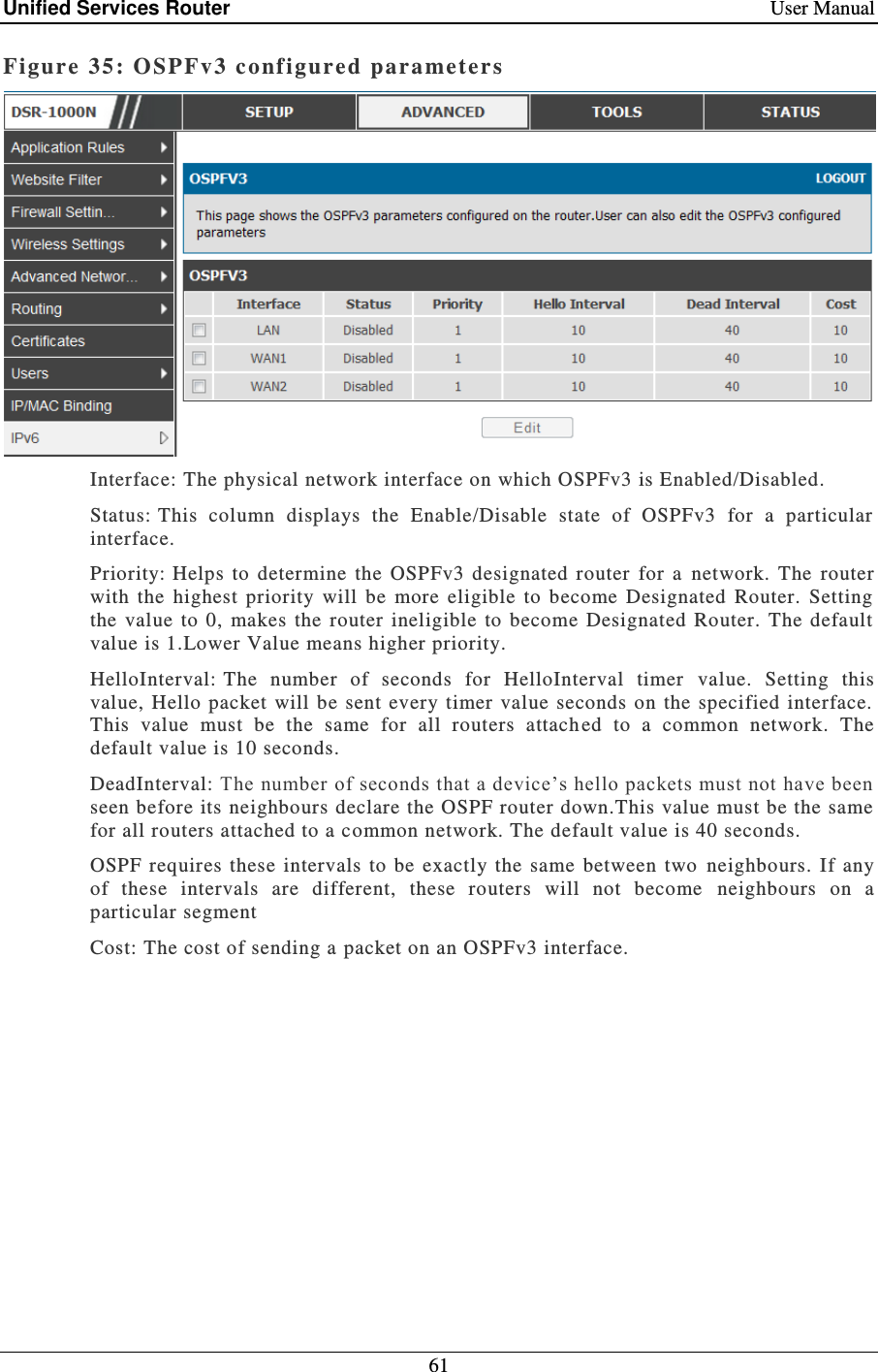
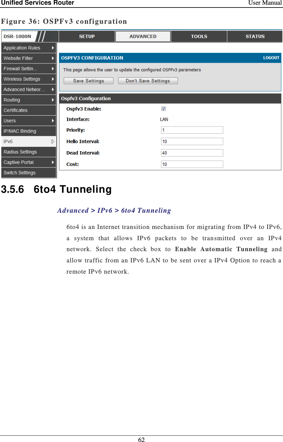
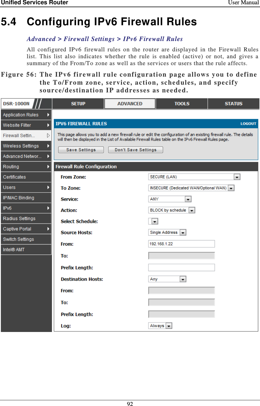

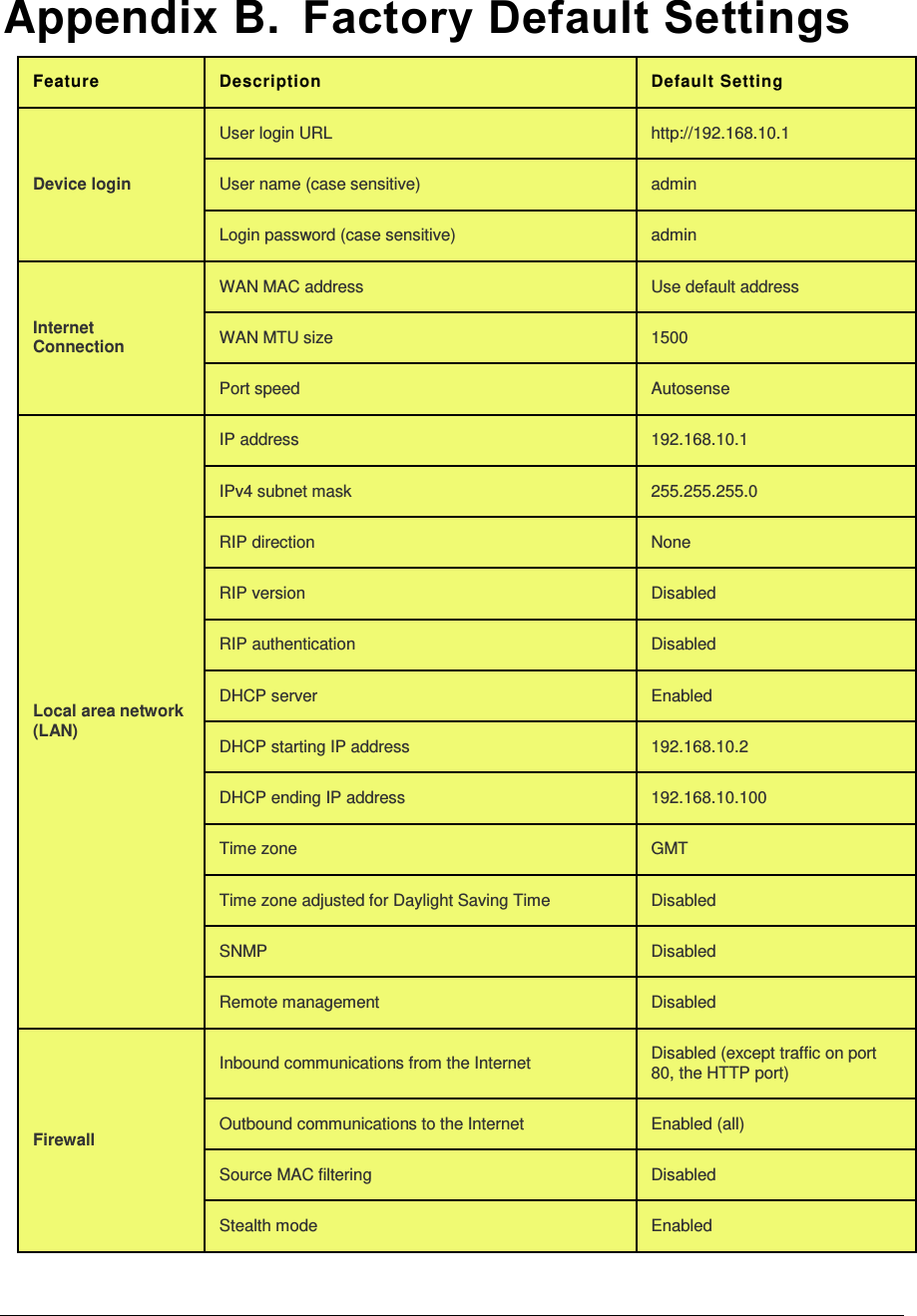
![Unified Services Router User Manual 202 nimfAdvOptSetWrap: user has changed MTU option DEBUG ddns: SQL error: %s ERROR nimfAdvOptSetWrap: MTU: %d DEBUG sqlite3QueryResGet failed.Query:%s ERROR nimfAdvOptSetWrap: old MTU size: %d DEBUG sqlite3QueryResGet failed.Query:%s ERROR nimfAdvOptSetWrap: old Port Speed Option: %d DEBUG ddnsDisable failed ERROR nimfAdvOptSetWrap: old Mac Address Option: %d DEBUG ddns: SQL error: %s ERROR nimfAdvOptSetWrap: MacAddress: %s DEBUG sqlite3QueryResGet failed.Query:%s ERROR Setting LED [%d]:[%d] For %s DEBUG sqlite3QueryResGet failed.Query:%s ERROR l2tpEnable: command string: %s DEBUG ddnsDisable failed ERROR nimfAdvOptSetWrap: handling reboot scenario DEBUG failed to call ddns enable ERROR nimfAdvOptSetWrap: INDICATOR = %d DEBUG ddns: SQL error: %s ERROR nimfAdvOptSetWrap: UpdateFlag: %d DEBUG ddnsDisable failed ERROR nimfAdvOptSetWrap: returning with status: %s DEBUG sqlite3QueryResGet failed.Query:%s ERROR nimfGetUpdateMacFlag: MacTable Flag is: %d DEBUG Error in executing DB update handler ERROR nimfMacGet: Mac Option changed DEBUG Failed to open the resolv.conf file. Exiting./n ERROR nimfMacGet: Update Flag: %d DEBUG Could not write to the resolv.conf file. Exiting. ERROR nimfMacGet: MacAddress: %s DEBUG Error opening the lanUptime File ERROR nimfMacGet: MacAddress: %s DEBUG Error Opening the lanUptime File. ERROR nimfMacGet: MacAddress: %s DEBUG failed to open %s ERROR nimfMacGet: MacAddress: %s DEBUG failed to open %s ERROR nimfMacGet: MacAddress: %s DEBUG failed to query networkInterface table ERROR nimfMacGet:Mac option Not changed \ DEBUG failed to query networkInterface table ERROR nimfMacGet: MacAddress: %s DEBUG sqlite3QueryResGet failed.Query:%s ERROR nimfMacGet: MacAddress: %s DEBUG failed to enable IPv6 forwarding ERROR nimfMacGet: MacAddress: %s DEBUG failed to set capabilities on the " ERROR nimfMacGet: returning with status: %s DEBUG failed to enable IPv6 forwarding ERROR Now in enableing LanBridge function DEBUG failed to set capabilities on the " ERROR sucessfully executed the command %s DEBUG failed to disable IPv6 forwarding ERROR Now in disableing LanBridge function DEBUG failed to set capabilities on the " ERROR sucessfully executed the command %s DEBUG failed to open %s ERROR configPortTblHandler:Now we are in Sqlite Update " DEBUG Could not create ISATAP Tunnel ERROR The Old Configuration of ConfiPort was:%s DEBUG Could not destroy ISATAP Tunnel ERROR The New Configuration of ConfiPort was:%s DEBUG Could not configure ISATAP Tunnel ERROR The user has deselected the configurable port DEBUG Could not de-configure ISATAP Tunnel ERROR failed query %s DEBUG nimfStatusUpdate: updating NimfStatus failed ERROR failed query %s DEBUG nimfStatusUpdate: updating NimfStatus failed ERROR failed query %s DEBUG nimfLinkStatusGet: determinig link's status failed ERROR %s:DBUpdate event: Table: %s opCode:%d rowId:%d DEBUG nimfLinkStatusGet: opening status file failed ERROR](https://usermanual.wiki/D-Link/SR150NA1/User-Guide-1654819-Page-204.png)
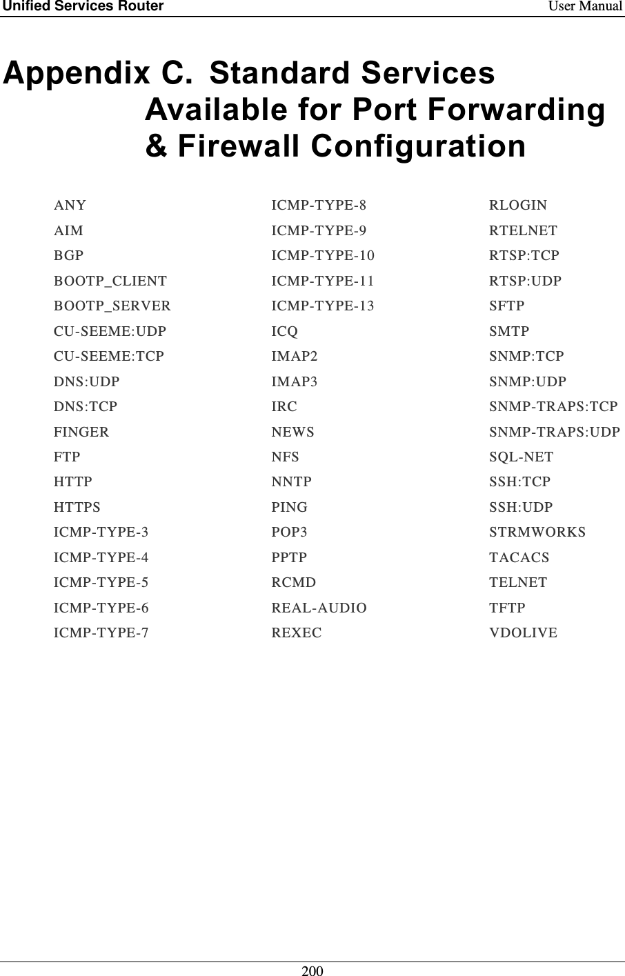
![Unified Services Router User Manual 204 pPrivSep: %s DEBUG nimfGetUpdateMacFlag: unable to get Flag from MacTable ERROR %s:DBUpdate event: Table: %s opCode:%d rowId:%d DEBUG nimfMacGet: Updating MAC address failed ERROR Re-Starting sshd daemon.... DEBUG sqlite3QueryResGet failed.Query:%s ERROR sshd re-started successfully. DEBUG error executing the command %s ERROR sshd stopped . DEBUG error executing the command %s ERROR failed query %s DEBUG error executing the command %s ERROR vlan disabled, not applying vlan configuration.. DEBUG disableLan function is failed to disable ConfigPort" ERROR failed query %s DEBUG sqlite3QueryResGet failed.Query:%s ERROR failed query %s DEBUG sqlite3QueryResGet failed.Query:%s ERROR no ports present in this vlanId %d DEBUG Unable to Disable configurable port from ERROR failed query %s DEBUG configPortTblHandler has failed ERROR vlan disabled, not applying vlan configuration.. DEBUG sqlite3QueryResGet failed.Query:%s ERROR disabling vlan DEBUG Error in executing DB update handler ERROR enabling vlan DEBUG sqlite3QueryResGet failed ERROR vlan disabled, not applying vlan configuration.. DEBUG Failed to execute switchConfig for port\ ERROR no ports present in this vlanId %d DEBUG Failed to execute switchConfig for port enable ERROR failed query %s DEBUG Failed to execute ifconfig for port enable ERROR vlan disabled, not applying vlan configuration.. DEBUG Failed to execute ethtool for\ ERROR removing %s from bridge%s... %s DEBUG Failed to execute switchConfig for port disable ERROR adding %s to bridge%d... %s DEBUG Failed to execute ifconfig for port disable ERROR restarting bridge... DEBUG sqlite3QueryResGet failed ERROR [switchConfig] Ignoring event on port number %d DEBUG sqlite3_mprintf failed ERROR restarting bridge... DEBUG sqlite3QueryResGet failed ERROR executing %s ... %s DEBUG Failed to execute switchConfig for port mirroring ERROR removing %s from bridge%s... %s DEBUG Usage:%s <DB Name> <Entry Name> <logFile> <subject> ERROR adding %s to bridge%d... %s DEBUG sqlite3QueryResGet failed ERROR [switchConfig] Ignoring event on %s DEBUG Could not get all the required variables to email the Logs. ERROR restarting bridge... DEBUG runSmtpClient failed ERROR [switchConfig] Ignoring event on port number %d DEBUG getaddrinfo returned %s ERROR [switchConfig] executing %s ... %s DEBUG file not found ERROR restarting bridge... DEBUG sqlite3QueryResGet failed.Query:%s ERROR UserName: %s DEBUG sqlite3QueryResGet failed.Query:%s ERROR Password: %s DEBUG sqlite3QueryResGet failed.Query:%s ERROR IspName: %s DEBUG No memory to allocate ERROR DialNumber: %s DEBUG Failed to Open SSHD Configuration File ERROR Apn: %s DEBUG Ipaddress should be provided with accessoption 1 ERROR](https://usermanual.wiki/D-Link/SR150NA1/User-Guide-1654819-Page-206.png)
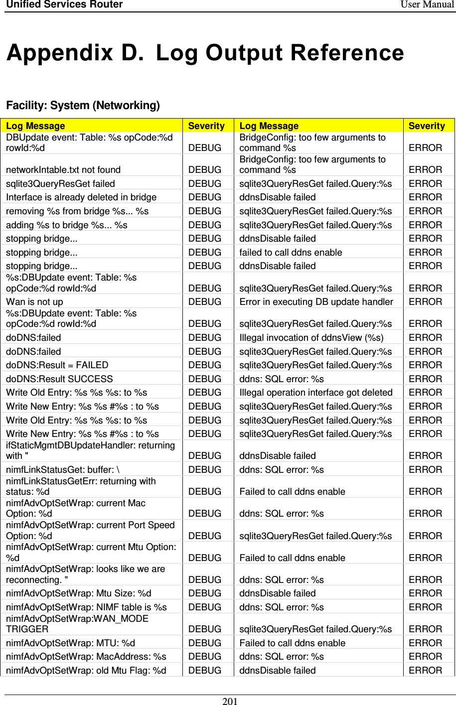
![Unified Services Router User Manual 215 Could not open database: %s DEBUG sqlite3QueryResGet failed ERROR CPU LOG File not found DEBUG radSendtoServer: socket: %s ERROR MEM LOG File not found DEBUG radSendtoServer: bind() Failed: %s: %s ERROR cpuMemUsageDBUpdateHandler: update query: %s DEBUG radRecvfromServer: recvfrom() Failed: %s ERROR Printing the whole list after inserting DEBUG radRecvfromServer: Packet too small from %s:%d: %s ERROR %s at %d(minute) %d(hour) %d(dayOfMonth) %d(month)" DEBUG radCheckMsgAuth: Invalid Message-Authenticator length in" ERROR adpCmdExec exited with return code=%d DEBUG radDictLoad: couldn't open dictionary %s: %s ERROR %s op=%d row=%d DEBUG radBuildAndSendReq: Invalid Request Code %d ERROR sqlite3_mprintf failed DEBUG radPairAssign: bad attribute value length ERROR sqlite3QueryResGet failed: query=%s DEBUG radPairAssign: unknown attribute type %d ERROR Printing the whole list after delete DEBUG radPairNew: unknown attribute %d ERROR %s at %d(minute) %d(hour) %d(dayOfMonth) %d(month)" DEBUG radPairGen: Attribute(%d) has invalid length ERROR Printing the whole list after inserting DEBUG radPairValue: unknown attribute type %d ERROR %s at %d(minute) %d(hour) %d(dayOfMonth) %d(month)" DEBUG radPairValueLen: unknown attribute type %d ERROR email logs: No logging events enabled DEBUG radPairLocate: Attribute(%d) has invalid length ERROR %s DEBUG radPairUnpackDefault: Unknown-Attribute[%d]: ERROR Mail sent and the Database is reset. DEBUG radConfigure: can't open %s: %s ERROR Disabled syslog server DEBUG radConfigure: %s: line %d: bogus format: %s ERROR Event logs are full, sending logs to email DEBUG radConfAssert: No AuthServer Specified ERROR Email logs sending failed DEBUG radConfAssert: No Default Timeout Specified ERROR Packing attribute: %s DEBUG radConfAssert: No Default Retry Count Specified ERROR Server found: %s, secret: %s DEBUG radExtractMppeKey: Invalid MS-MPPE-Key Length ERROR Packed Auth. Reqest: code:%d, id:%d, len:%d DEBUG radVendorMessage: Invalid Length in Vendor Message ERROR Sending Packet to %x:%d .... DEBUG radVendorMessage: Unknown Vendor ID received:%d ERROR Receiving Reply Packet.... DEBUG radVendorAttrGet: Invalid Length in Vendor Message ERROR Verified Reply Packet Integrity DEBUG radVendorAttrGet: Unknown Vendor ID:%d ERROR Generated Reply Attribute-Value pairs DEBUG radVendorMessagePack: Unknown Vendor ID:%d ERROR Verified Message-Authenticator DEBUG radGetIPByName: couldn't resolve hostname: %s ERROR Unloaded RADIUS Dictionary DEBUG radGetHostIP: couldn't get hostname ERROR Adding Dictionary Attribute %s DEBUG radGetHostIP: couldn't get host IP address ERROR Adding Dictionary Value %s DEBUG radius dictionary loading failed ERROR Loaded Dictionary %s DEBUG Failed to set default timeout value ERROR](https://usermanual.wiki/D-Link/SR150NA1/User-Guide-1654819-Page-217.png)
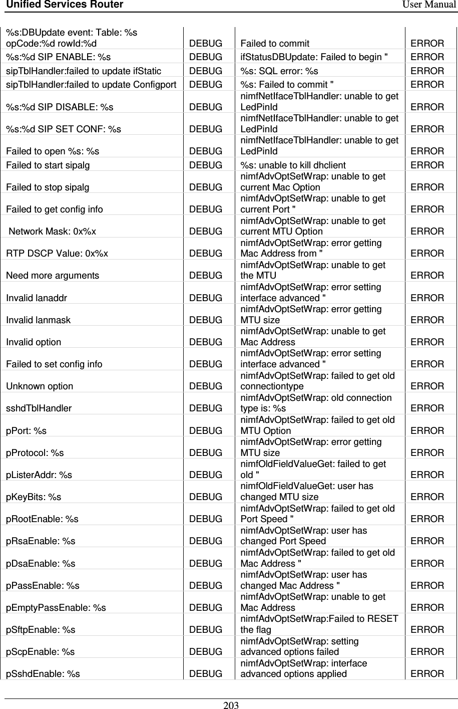
![Unified Services Router User Manual 217 Next Synchronization after" DEBUG Unable to set debug for radAuth. ERROR Next Synchronization after %d \ DEBUG Unable to set debug level for radAuth. ERROR Primary is not available, " DEBUG ERROR: option value not specified ERROR Secondary is not available, " DEBUG Unable to initialize radius ERROR Invalid value for use default servers, " DEBUG Invalid username, challenge or response ERROR No server is configured, " DEBUG Unable to set debug for radAuth. ERROR Backing off for %d seconds DEBUG Unable to set debug level for radAuth. ERROR Requesting time from %s DEBUG ERROR: option value not specified ERROR Synchronized time with %s DEBUG Unable to initialize radius ERROR Received KOD packet from %s DEBUG Invalid username or password ERROR No suitable server found %s DEBUG usage : %s <DB fileName> ERROR Received Invalid Length packet from %s DEBUG ntpd : umi initialization failed ERROR Received Invalid Version packet from %s DEBUG ntpd : ntpInit failed ERROR Received Invalid Mode packet from %s DEBUG ntpd : ntpMgmtInit failed ERROR Request Timed out from %s DEBUG There was an error while getting the timeZoneChangeScript." ERROR Looking Up %s DEBUG unexpected reply from %d cmd=%d ! ERROR Timezone difference :%d DEBUG cmd %d not supported. caller %d ERROR Could not open file: %s DEBUG default reached ERROR Could not read data from file DEBUG Unable to initialize ntpControl ERROR ntpTblHandler DEBUG ntpMgmt : Couldn't open database %s ERROR status: %d DEBUG ERROR : incomplete DB update information ERROR tz: %d DEBUG empty update. nRows=%d nCols=%d ERROR DayLightsaving: %d DEBUG Error in executing DB update handler ERROR pNtpControl->ServerNames[PRIMARY_SERVER]: %s DEBUG requestNtpTime: Invalid addr ERROR pNtpControl->ServerNames[SECONDARY_SERVER]: %s DEBUG failed to take lock for compId: %d ERROR DS: %d DEBUG failed to convert ioctl args to buffer for" ERROR pPriServ %s DEBUG request timeout dst(%d) <-- src(%d) ERROR pSecServ %s DEBUG failed to take lock for compId: %d ERROR Making request from %d --> %d DEBUG umiIoctlArgsToBuf: failed to allocate memory ERROR sent request dst(%d) <-- src(%d) using option %d DEBUG umiRecvFrom: could not allocate memory ERROR received request too small!(%d bytes) DEBUG adpMalloc failed ERROR Received a UMI request from %d DEBUG context with ID: %d already registered ERROR sent a reply src(%d) ---> dst(%d) DEBUG Failed to allocate memory for creating UMI context ERROR umiRegister (%x,%x,%x,%x) DEBUG Failed to create recvSem for UMI context ERROR srcId=%d(%s) --> destId=%d(%s) cmd=%d inLen=%d outLen=%d DEBUG Failed to create mutex locks for UMI context ERROR waiting for reply...Giving Up DEBUG Failed to create mutex recvQLock for UMI context ERROR No request in the list after semTake DEBUG Invalid arguments to umiIoctl ERROR reply timeout DEBUG could not find the destination context ERROR](https://usermanual.wiki/D-Link/SR150NA1/User-Guide-1654819-Page-219.png)
![Unified Services Router User Manual 218 timeout after semTake DEBUG memPartAlloc for %d size failed ERROR srcId=%d(%s) <-- destId=%d(%s) cmd=%d DEBUG memPartAlloc for %d size failed ERROR Un-registerting component with Id %d DEBUG No Handler registered for this UMI context ERROR failed to send ioctl request: dst(%d) <--- src(%d) DEBUG Couldn't find component with ID (%d)," ERROR processed a reply dst(%d) <-- src(%d) DEBUG id=%d handler=%x ERROR request with no result option dst(%d) <-- src(%d) DEBUG Received NULL buffer in umiBufToIoctlArgs() ERROR cmd = %s DEBUG usbMgmtInit: unable to open the database file %s ERROR cmdstring is %s %s:%d DEBUG call to printConfig failed ERROR Calling printerConfig binary ... DEBUG Failed to Disable Network Storage" ERROR Calling unmount for USB ... DEBUG Some error occurred while removing device ERROR Calling mount for USB ... DEBUG Some error occurred while removing device ERROR usbdevice is %d %s:%d DEBUG Sqlite update failed ERROR Query string: %s DEBUG Failed to enable printer properly ERROR sqlite3QueryResGet failed.Query:%s DEBUG Failed to mount device on system ERROR %s: 1. usb is already disconnected for old usb type. " DEBUG Failed to enable network storage device" ERROR %s: 2.call disable for new usb type ! DEBUG Failed to mount device on system ERROR %s: 3. usb is already disconnected for old usb type. " DEBUG Sqlite update failed ERROR %s: 4. Disabled old usb type . Now " DEBUG USB1 Touch failed ERROR usbdevice is %d %s:%d DEBUG USB2 Touch failed ERROR USB: failed to begin transaction: %s DEBUG Sqlite update failed ERROR USB: SQL error: %s pSetString = %s DEBUG Failed query: %s ERROR USB: failed to commit transaction: %s DEBUG Failed to execute usb database update handler ERROR USB: updated table: %s DEBUG Usage:%s <DBFile> <opType> <tblName> <rowId> ERROR USB: returning with status: %s DEBUG Illegal invocation of snmpConfig (%s) ERROR %s:DBUpdate event: Table: %s opCode:%d rowId:%d DEBUG Invalid Community Access Type ERROR executing %s status =%d DEBUG Invalid User Access Type ERROR executing %s DEBUG Invalid Security Level ERROR %s returned status=%d DEBUG Invalid Authentication Algorithm ERROR %s returned status=%d DEBUG Invalid Privacy Algorithm ERROR snmpd.conf not found DEBUG Invalid Argument ERROR [SNMP_DEBUG] : Fwrite Successful DEBUG Failed to allocate memory for engineID ERROR [SNMP_DEBUG] : Fwrite failed DEBUG [SNMP_DEBUG]: Failed to get host address ERROR radPairGen: received unknown attribute %d of length %d WARN [SNMP_DEBUG] : FOPEN failed ERROR radPairGen: %s has unknown type WARN sqlite3QueryResGet failed.Query:%s ERROR radPairLocate: unknown attribute %ld of length %d WARN sqlite3QueryResGet failed.Query:%s ERROR radPairLocate: %s has unknown type WARN Invalid Security Level ERROR Illegal invocation of cpuMemUsage (%s) ERROR Invalid Authentication Algorithm ERROR](https://usermanual.wiki/D-Link/SR150NA1/User-Guide-1654819-Page-220.png)
![Unified Services Router User Manual 221 Enabling attack check for L2TP. DEBUG Updating BlockSites Keyword from \ DEBUG Enabling attack check for UDP Flood. DEBUG Inserting BlockSites Keyword \ DEBUG Enabling attack check for IPsec. DEBUG Deleting Trusted Domain \ DEBUG Enabling attack check for PPTP. DEBUG Adding Trusted Domain \ DEBUG Enabling attack check for L2TP. DEBUG Restarting Schedule Based Firewall Rules DEBUG Enabling DoS attack check with %d SyncFlood detect rate, " DEBUG Enabling Remote SNMP DEBUG Disabling DoS attack check having %d SyncFlood detect rate," DEBUG Disabling Remote SNMP DEBUG Enabling ICSA Notification Item for ICMP notification. DEBUG Enabling Remote SNMP DEBUG Enabling ICSA Notification Item for Fragmented Packets. DEBUG Disabling DOS Attacks DEBUG Enabling ICSA Notification Item for Multi cast Packets. DEBUG Enabling DOS Attacks DEBUG Disabling ICSA Notification Item for ICMP notification. DEBUG Enabling DOS Attacks DEBUG Disabling ICSA Notification Item for Fragmented Packets. DEBUG Restarting Firewall [%d]:[%d] For %s DEBUG Disabling ICSA Notification Item for Multi cast Packets. DEBUG restartStatus = %d for LogicalIfName = %s DEBUG Adding IP/MAC binding rule for %s MAC address " DEBUG Deleting Lan Group %s DEBUG Deleting IP/MAC binding rule for %s MAC " DEBUG Adding Lan Group %s DEBUG ./src/firewall/linux/user/firewalld.c:60:#undef ADP_DEBUG DEBUG Deleting lan host %s from group %s DEBUG ./src/firewall/linux/user/firewalld.c:62:#define ADP_DEBUG printf DEBUG Adding lan host %s from group %s DEBUG Restarting traffic meter with %d mins, %d hours, " DEBUG Disabling Firewall Rule for IGMP Protocol DEBUG Updating traffic meter with %d mins, %d hours, " DEBUG Enabling Firewall Rule for IGMP Protocol DEBUG Deleting traffic meter. DEBUG Deleting IP/MAC Bind Rule for MAC address %s and IP " DEBUG Disabling block traffic for traffic meter. DEBUG Adding IP/MAC Bind Rule for MAC address %s and IP DEBUG Enabling traffic meter. DEBUG Deleting Protocol Bind Rule for Service %s DEBUG Adding lan group %s. DEBUG Deleting Protocol Bind Rule for Service %s DEBUG Deleting lan group %s. DEBUG Deleting Protocol Bind Rule for Service %s DEBUG Renaming lan group from %s to %s. DEBUG Adding Protocol Bind Rule for Service %s DEBUG Deleting host %s from %s group. DEBUG %s Session Settings DEBUG Adding host %s to %s group. DEBUG Restarting IPv6 Firewall Rules... DEBUG Enabling Keyword blocking for %s keyword. DEBUG Deleting Port Trigger Rule for %d:%d:%d:%d:%d DEBUG Disabling keyword Blocking for %s keyword . DEBUG Deleting Port Trigger Rule for %d:%d:%d:%d:%d DEBUG Deleting trusted domain with keyword %s. DEBUG Enabling Port Trigger Rule for %d:%d:%d:%d:%d DEBUG Adding %s keyword to trusted domain. DEBUG Disabling Port Trigger Rule for %d:%d:%d:%d:%d DEBUG Enabling Management Access from DEBUG Enabling Port Trigger Rule for DEBUG](https://usermanual.wiki/D-Link/SR150NA1/User-Guide-1654819-Page-223.png)
![Unified Services Router User Manual 223 Update FirewallRules6 where ScheduleName = '%s' to New " DEBUG fwLBSpillOverConfigure: Could not set POSTROUTING rules ERROR Dns proxy Restart failed DEBUG fwLBSpillOverConfigure: Something going wrong Here ERROR deleting interface to ifgroup failed DEBUG fwL2TPGenericRules.c: unable to open the database file " ERROR adding interface to ifgroup failed DEBUG fwL2TPGenericRules.c: inet_aton failed ERROR deleting interface pVirtIface %s from ifgroup %d" DEBUG fwPPTPGenericRules.c: unable to open the database file " ERROR adding interface pVirtIface %s to ifgroup %d failed DEBUG fwPPTPGenericRules.c: inet_aton failed ERROR Deleting IP address %s. DEBUG DNS proxy firewall rule add failed for %s ERROR Adding new IP address %s. DEBUG deleting interface %s from ifgroup %d failed ERROR Updating old IP address %s to new IP address %s. DEBUG adding interface %s to ifgroup %d failed ERROR Restarting Firewall For %s Address Update from %s:%s DEBUG nimfBridgeTblHandler: unable to get interfaceName ERROR Disabling Firewall Rule for MSS packet marking DEBUG nimfBridgeTblHandler: \ ERROR Enabling Firewall Rule for MSS packet marking DEBUG nimfBridgeTblHandler: unable to get \ ERROR Enabling packet marking rule for %s IDLE timer DEBUG Failed to %s traffic from %s to %s to IPS. ERROR Deleted firewall rule %s for service %s with action %s DEBUG Failed to %s traffic from %s to %s to IPS. ERROR %s firewall rule %s for service %s with action %s DEBUG failed to start IPS service. ERROR Added firewall rule %s for service %s with action %s DEBUG Timeout in waiting for IPS service to start. ERROR Deleting inbound(WAN-LAN) firewall rule. DEBUG Usage:%s <DBFile> <opType> <tblName> <rowId> " ERROR Deleting inbound(WAN-DMZ) firewall rule. DEBUG xlr8NatConfig: illegal invocation of (%s) ERROR RIPng disabled. DEBUG Illegal invocation of [%s] ERROR RIPng enabled. DEBUG xlr8NatMgmtTblHandler: failed query: %s ERROR Disable IPv6 firewall rule. DEBUG Could not open file: %s ERROR Enable IPv6 firewall rule. DEBUG Rip Error Command Too Long ERROR Deleting IGMP proxy rule. DEBUG No authentication for Ripv1 ERROR Enable IGMP proxy rule. DEBUG Invalid Rip Direction ERROR Restarting IGMP rule. DEBUG Invalid Rip Version ERROR Traffic meter enabled with no limit type. DEBUG Invalid Password for 1st Key ERROR Traffic meter enabled for only download. DEBUG Invalid Time for 1st Key ERROR Traffic meter enabled for both directions. DEBUG Invalid Password for 2nd Key ERROR Deleted firewall rule %s for service %s with action %s DEBUG Invalid Time for 2nd Key ERROR %s firewall rule %s for service %s with action %s DEBUG Invalid First KeyId ERROR Added firewall rule %s for service %s with action %s DEBUG Invalid Second KeyId ERROR Enabling Inter VLAN routing. DEBUG Invalid Authentication Type ERROR Updating inter VLAN routing status. DEBUG ripDisable failed ERROR Deleting inter VLAN routing. DEBUG ripEnable failed ERROR](https://usermanual.wiki/D-Link/SR150NA1/User-Guide-1654819-Page-225.png)
![Unified Services Router User Manual 228 from pnacRecvMapi: pkt body len = %d, pktType = %d DEBUG eapolRecvKeyMsg: invalid descriptor version ERROR from pnacPDUProcess: received PNAC_EAP_PACKET DEBUG eapolRecvKeyMsg: incorrect descriptor version ERROR from pnacPDUProcess: currentId = %d DEBUG eapolRecvKeyMsg: Ack must not be set ERROR from pnacPDUProcess: code = %d, identifier = %d, " DEBUG eapolRecvKeyMsg: MIC bit must be set ERROR from pnacPDUProcess: setting rxResp true DEBUG wpaAuthRecvPTKMsg2: unexpected packet received ERROR from pnacPDUProcess: code = %d, identifier = %d, " DEBUG wpaAuthRecvPTKMsg2: mic check failed ERROR from pnacPDUProcess: received " DEBUG wpaAuthRecvPTKMsg2: rsn ie mismatch ERROR from pnacPDUProcess: received " DEBUG wpaAuthRecvPTKMsg4: unexpected packet received ERROR from pnacPDUProcess: received PNAC_EAPOL_KEY_PACKET DEBUG wpaAuthRecvPTKMsg4: keyDataLength not zero ERROR doing pnacTxCannedFail DEBUG wpaAuthRecvPTKMsg4: mic check failed ERROR doing pnacTxCannedSuccess DEBUG wpaAuthRecvGTKMsg2: unexpected packet received ERROR doing pnacTxReqId DEBUG secureBit not set in GTK Msg2 ERROR doing pnacTxReq DEBUG wpaAuthRecvGTKMsg2: keyDataLength not zero ERROR doing pnacTxStart DEBUG wpaAuthRecvGTKMsg2: mic check failed ERROR doing pnacTxLogoff DEBUG wpaAuthRecvKeyReq: unexpected packet received ERROR doing pnacTxRspId: 1st cond DEBUG wpaAuthRecvKeyReq: keyDataLength not zero ERROR doing pnacTxRspId: entering 2nd cond DEBUG wpaAuthRecvKeyReq: mic check failed ERROR from pnacTxRspId: code = %d, identifier = %d, length = %d, " DEBUG invalid OUI %x %x %x ERROR doing pnacTxRspId: 2nd cond DEBUG (%s) invalid OUI %x %x %x ERROR doing pnacTxRspAuth: 1st cond DEBUG [%s:%d] Cipher in WPA IE : %x ERROR doing pnacTxRspAuth: 2nd cond DEBUG (%s) invalid OUI %x %x %x ERROR message for unknown port PAE DEBUG short WPA IE (length = %d) received ERROR from pnacACToSuppRecvRtn: calling pnacEapPktRecord DEBUG PTK state machine in unknown state. ERROR from pnacEapPktRecord: code = %d, identifier = %d, " DEBUG dot11InstallKeys failed ERROR from pnacEapPktRecord: received success pkt DEBUG group state machine entered into WPA_AUTH_GTK_INIT ERROR from pnacEapPktRecord: received failure pkt DEBUG dot11Malloc failed ERROR from pnacEapPktRecord: received request pkt DEBUG dot11Malloc failed ERROR unknown EAP-code %d DEBUG dot11Malloc failed ERROR Authenticator[%d]: DEBUG aesWrap failed ERROR Auth PAE state = %s DEBUG unknown key descriptor version %d ERROR Auth Reauth state = %s DEBUG dot11Malloc failed ERROR Back auth state = %s DEBUG could not initialize AES128ECB ERROR Supplicant[%d]: DEBUG could not initialize AES-128-ECB ERROR Supp Pae state = %s DEBUG MD5 initialization failed ERROR](https://usermanual.wiki/D-Link/SR150NA1/User-Guide-1654819-Page-230.png)
![Unified Services Router User Manual 229 from pnacBackAuthFail: calling pnacTxCannedFail DEBUG RC4 framework initialization failed ERROR %s returned ERROR DEBUG PNAC framework initialization failed ERROR pnacUmiIoctlHandler: cmd: %s(%d) DEBUG ERROR: option value not specified ERROR %s not configured for 802.1x DEBUG ERROR: -u can be used only with -s ERROR could not process PDU received from the wire DEBUG ERROR: user-name not specified ERROR pnacPDUForward: failed to foward the received PDU DEBUG failed to enable debug ERROR Creating PHY port with AUTH backend : %s SendRtn: %p RecvRtn:%p DEBUG [%s]: failed to convert string to MAC " ERROR pnacUmiAuthConfig: %s not configured for 802.1x DEBUG failed to initialize UMI ERROR pnacSuppRegisterUserInfo: not a valid AC DEBUG pnacPhyPortParamSet:invalid arguments ERROR pnacIfConfig: autoAuth Enabled DEBUG pnacPhyPortParamSet:Failed to create socket ERROR pnacSendRtn: no pnac port pae found for " DEBUG Error from pnacPhyPortParamSet:%s-device invalid ERROR sending portStatus: %s[%d] to dot11 DEBUG Error from pnacPhyPortParamSet:%s-Getting MAC address " ERROR pnacRecvASInfoMessage: Rkey of length %d set DEBUG pnacPhyPortParamSet:Failed to add 802.1X multicast " ERROR ASSendRtn: %p ASToAuthRecv: %p DEBUG pnacIsInterfaceUp: failed to create a raw socket ERROR adpRand failed:unable to generate random unicast key WARN pnacIsInterfaceUp: failed to get interface flags ERROR using group key as unicast key WARN failed to allocate buffer ERROR Integrity check failed more than once in last 60 secs. WARN UMI initialization failed ERROR MIC failed twice in last 60 secs, taking countermeasures WARN UMI initialization failed ERROR Failed to set dot11 port status WARN Error from pnacEapDemoAuthLibInit: malloc failed ERROR PTK state machine in NO_STATE. WARN Error from pnacEapDemoAuthRecv: received null EAP pkt ERROR PTK state machine in NO_STATE!! WARN Error from pnacEapDemoAuthRecv: send " ERROR PMKSA refcount not 1 WARN Error from pnacRadXlateASAdd: cannot open socket ERROR IV verification failednknown subtype> WARN Error from pnacRadXlateDemoRecv: received null EAP pkt ERROR pnacIfConfig: overwriting previous interface " WARN From pnacRadXlateDemoRecv: send " ERROR pnacIfConfig: overwriting previous " WARN Error from pnacRadXlateDemoRecv: radius " ERROR pnacIfConfig: overwriting previous username" WARN Error from pnacRadXlateDemoRecv: radius " ERROR pnacIfConfig: overwriting previous password" WARN Error from pnacRadXlateRadIdRespSend: send to failed ERROR %s: Failed to set port status WARN Error from pnacRadXlateRadNonIdRespSend: send to failed ERROR %s: Failed to notify event to dot11 WARN Error from pnacRadXlateRadRecvProc: recvfrom failed ERROR pnacLibDeinit: Failed to destroy the WARN From ERROR](https://usermanual.wiki/D-Link/SR150NA1/User-Guide-1654819-Page-231.png)
![Unified Services Router User Manual 233 Error in executing DB update handler ERROR pnacEapRadAuthSend: Invalid arguments ERROR sqlite3QueryResGet failed ERROR pnacEapRadAuthSend: failed to allocate inbuffer ERROR ERROR: incomplete DB update information. ERROR pnacXmit : umiIoctl failed[%d] ERROR old values result does not contain 2 rows ERROR pnacPDUForward: Invalid input ERROR sqlite3QueryResGet failed ERROR pnacPDUForward: error in getting port pae information ERROR Error in executing DB update handler ERROR pnacPDUForward: error allocating memory ERROR sqlite3QueryResGet failed.Query:%s ERROR pnacUmiIfMacAddrChange: %s not configured for 802.1x ERROR sqlite3QueryResGet failed.Query:%s ERROR pnacUmiIfMacAddrChange: could not process PDU received" ERROR sqlite3QueryResGet failed.Query:%s ERROR pnacUmiPhyPortConfig: Invalid config data ERROR sqlite3QueryResGet failed.Query:%s ERROR pnacUmiPhyPortConfig: Invalid backend name specified ERROR startStopVap failed to stop %s ERROR pnacUmiPhyPortConfig: could not create PNAC physical" ERROR Invalid SQLITE operation code - %d ERROR pnacUmiAuthConfig: Invalid config data ERROR ./src/dot11/mgmt/dot11Mgmt.c:1177: ADP_ERROR ( ERROR pnacUmiAuthConfig: Invalid backend name specified ERROR only delete event expected on dot11RogueAP. ERROR unable to create new EAP context. ERROR sqlite3QueryResGet failed ERROR unable to apply %s profile on the EAP context. ERROR unhandled database operation %d ERROR pnacUmiAuthConfig: could not configure PNAC PAE " ERROR sqlite3QueryResGet failed ERROR pnacUmiSuppConfig: Invalid config data ERROR failed to configure WPS on %s ERROR pnacUmiSuppConfig: Invalid backend name specified ERROR sqlite3QueryResGet failed ERROR pnacUmiSuppConfig: %s not configured for 802.1x ERROR sqlite3QueryResGet failed ERROR pnacUmiSuppConfig: could not PNAC port Access" ERROR sqlite3QueryResGet failed ERROR pnacUmiSuppConfig: Failed to register user information ERROR sqlite3QueryResGet failed ERROR pnacPortByMacDeconfig: port not found ERROR sqlite3QueryResGet failed ERROR pnacPortByMacDeconfig: port not found ERROR no VAP rows returned. expected one ERROR pnacUmiIfDown: Invalid config data ERROR multiple VAP rows returned. expected one ERROR pnacUmiIfDown: Invalid config data ERROR sqlite3QueryResGet failed ERROR Error from pnacPortDeconfig: port not configured ERROR invalid query result. ncols=%d nrows=%d ERROR pnacUmiIfDown: could not de-configure port ERROR %s:VAP(%s) create failed ERROR pnacUmiPhyPortDestroy: Invalid config data ERROR sqlite3QueryResGet failed ERROR pnacUmiPhyPortDestroy: Invalid config data ERROR invalid query result. ncols=%d nrows=%d ERROR pnacUmiPhyPortDestroy: Failed to destroy the port ERROR](https://usermanual.wiki/D-Link/SR150NA1/User-Guide-1654819-Page-235.png)
![Unified Services Router User Manual 234 Invalid config data ERROR Facility: Kernel Log Message Severity Log Message Severity DNAT: multiple ranges no longer supported DEBUG %s: %s%s:%d -> %s:%d %s, DEBUG DNAT: Target size %u wrong for %u ranges, DEBUG %s: %s%s:%d %s, DEBUG DNAT: wrong table %s, tablename DEBUG %s: Failed to add WDS MAC: %s, dev->name, DEBUG DNAT: hook mask 0x%x bad, hook_mask DEBUG %s: Device already has WDS mac address attached, DEBUG %s%d: resetting MPPC/MPPE compressor, DEBUG %s: Added WDS MAC: %s, dev->name, DEBUG %s%d: wrong offset value: %d, DEBUG %s: WDS MAC address %s is not known by this interface, DEBUG %s%d: wrong length of match value: %d, DEBUG [madwifi] %s() : Not enough space., __FUNCTION__ DEBUG %s%d: too big offset value: %d, DEBUG Returning to chan %d, ieeeChan DEBUG %s%d: cannot decode offset value, DEBUG WEP DEBUG %s%d: wrong length code: 0x%X, DEBUG AES DEBUG %s%d: short packet (len=%d), __FUNCTION__, DEBUG AES_CCM DEBUG %s%d: bad sequence number: %d, expected: %d, DEBUG CKIP DEBUG %s%d: bad sequence number: %d, expected: %d, DEBUG TKIP DEBUG PPPIOCDETACH file->f_count=%d, DEBUG %s: cannot map channel to mode; freq %u flags 0x%x, DEBUG PPP: outbound frame not passed DEBUG %s: %s, vap->iv_dev->name, buf DEBUG PPP: VJ decompression error DEBUG %s: [%s] %s, vap->iv_dev->name, DEBUG PPP: inbound frame not passed DEBUG %s: [%s] %s, vap->iv_dev->name, ether_sprintf(mac), buf DEBUG PPP: reconstructed packet DEBUG [%s:%s] discard %s frame, %s, vap->iv_dev->name, DEBUG PPP: no memory for DEBUG [%s:%s] discard frame, %s, vap->iv_dev->name, DEBUG missed pkts %u..%u, DEBUG [%s:%s] discard %s information element, %s, DEBUG %s%d: resetting MPPC/MPPE compressor, DEBUG [%s:%s] discard information element, %s, DEBUG %s%d: wrong offset value: %d, DEBUG [%s:%s] discard %s frame, %s, vap->iv_dev->name, DEBUG %s%d: wrong length of match value: %d, DEBUG [%s:%s] discard frame, %s, vap->iv_dev->name, DEBUG %s%d: too big offset value: %d, DEBUG ifmedia_add: null ifm DEBUG %s%d: cannot decode offset value, DEBUG Adding entry for DEBUG %s%d: wrong length code: 0x%X, DEBUG ifmedia_set: no match for 0x%x/0x%x, DEBUG %s%d: short packet (len=%d), __FUNCTION__, DEBUG ifmedia_set: target DEBUG %s%d: bad sequence number: %d, expected: %d, DEBUG ifmedia_set: setting to DEBUG](https://usermanual.wiki/D-Link/SR150NA1/User-Guide-1654819-Page-236.png)
![Unified Services Router User Manual 235 %s%d: bad sequence number: %d, expected: %d, DEBUG ifmedia_ioctl: no media found for 0x%x, DEBUG PPPIOCDETACH file->f_count=%d, DEBUG ifmedia_ioctl: switching %s to , dev->name DEBUG PPP: outbound frame not passed DEBUG ifmedia_match: multiple match for DEBUG PPP: VJ decompression error DEBUG <unknown type> DEBUG PPP: inbound frame not passed DEBUG desc->ifmt_string DEBUG PPP: reconstructed packet DEBUG mode %s, desc->ifmt_string DEBUG PPP: no memory for DEBUG <unknown subtype> DEBUG missed pkts %u..%u, DEBUG %s, desc->ifmt_string DEBUG %s: INC_USE_COUNT, now %d, __FUNCTION__, mod_use_count \ DEBUG %s%s, seen_option++ ? , : , DEBUG %s: DEC_USE_COUNT, now %d, __FUNCTION__, mod_use_count \ DEBUG %s%s, seen_option++ ? , : , DEBUG PPPOL2TP %s: _fmt, DEBUG %s, seen_option ? > : DEBUG PPPOL2TP: --> %s, __FUNCTION__) DEBUG %s: %s, dev->name, buf DEBUG PPPOL2TP: <-- %s, __FUNCTION__) DEBUG %s: no memory for sysctl table!, __func__ DEBUG %s: recv: , tunnel->name DEBUG %s: no memory for VAP name!, __func__ DEBUG %s: xmit:, session->name DEBUG %s: failed to register sysctls!, vap->iv_dev->name DEBUG %s: xmit:, session->name DEBUG %s: no memory for new proc entry (%s)!, __func__, DEBUG %s: module use_count is %d, __FUNCTION__, mod_use_count DEBUG %s: 0x%p len %u, tag, p, len DEBUG PPPOL2TP %s: _fmt, DEBUG %03d:, i DEBUG PPPOL2TP: --> %s, __FUNCTION__) DEBUG %02x, ((u_int8_t *)p)[i] DEBUG PPPOL2TP: <-- %s, __FUNCTION__) DEBUG first difference at byte %u, i DEBUG %s: recv: , tunnel->name DEBUG %s: , t->name DEBUG %s: xmit:, session->name DEBUG FAIL: ieee80211_crypto_newkey failed DEBUG %s: xmit:, session->name DEBUG FAIL: ieee80211_crypto_setkey failed DEBUG PPPOL2TP %s: _fmt, DEBUG FAIL: unable to allocate skbuff DEBUG PPPOL2TP: --> %s, __FUNCTION__) DEBUG FAIL: wep decap failed DEBUG PPPOL2TP: <-- %s, __FUNCTION__) DEBUG FAIL: decap botch; length mismatch DEBUG %s: recv: , tunnel->name DEBUG FAIL: decap botch; data does not compare DEBUG %s: xmit:, session->name DEBUG FAIL: wep encap failed DEBUG %s: xmit:, session->name DEBUG FAIL: encap data length mismatch DEBUG IRQ 31 is triggered DEBUG FAIL: encrypt data does not compare DEBUG [%s:%d] , __func__, __LINE__\ DEBUG PASS DEBUG \t[R%s %#0x %#0x 0x%08x%08x], (status == ERROR ? # : ), page, addr, (uint32_t)(*pValue >> 32), (uint32_t)(*pValue & 0xffffffff) DEBUG %u of %u 802.11i WEP test vectors passed, pass, total DEBUG \t[W%s %#0x %#0x 0x%08x%08x], (status == ERROR ? # : ), page, addr, (uint32_t)(value >> 32), (uint32_t)(value & 0xffffffff) DEBUG %s: 0x%p len %u, tag, p, len DEBUG %s: mac_add %02X:%02X:%02X:%02X:%02X:%02X, dev->name, addr[0], addr[1], addr[2], addr[3], addr[4], addr[5] DEBUG %03d:, i DEBUG](https://usermanual.wiki/D-Link/SR150NA1/User-Guide-1654819-Page-237.png)
![Unified Services Router User Manual 236 %s: mac_del %02X:%02X:%02X:%02X:%02X:%02X, dev->name, addr[0], addr[1], addr[2], addr[3], addr[4], addr[5] DEBUG %02x, ((u_int8_t *)p)[i] DEBUG %s: mac_kick %02X:%02X:%02X:%02X:%02X:%02X, dev->name, addr[0], addr[1], addr[2], addr[3], addr[4], addr[5] DEBUG first difference at byte %u, i DEBUG %s: mac_undefined %02X:%02X:%02X:%02X:%02X:%02X, dev->name, addr[0], addr[1], addr[2], addr[3], addr[4], addr[5] DEBUG %s: , t->name DEBUG %s: addr_add %02X:%02X:%02X:%02X:%02X:%02X, dev->name, addr[0], addr[1], addr[2], addr[3], addr[4], addr[5] DEBUG FAIL: ieee80211_crypto_newkey failed DEBUG %s: addr_del %02X:%02X:%02X:%02X:%02X:%02X, dev->name, addr[0], addr[1], addr[2], addr[3], addr[4], addr[5] DEBUG FAIL: ieee80211_crypto_setkey failed DEBUG %s: mac_undefined %02X:%02X:%02X:%02X:%02X:%02X, dev->name, addr[0], addr[1], addr[2], addr[3], addr[4], addr[5] DEBUG FAIL: unable to allocate skbuff DEBUG %s: set_float %d;%d, DEBUG FAIL: ccmp encap failed DEBUG IRQ 32 is triggered DEBUG FAIL: encap data length mismatch DEBUG ip_finish_output2: No header cache and no neighbour! DEBUG FAIL: encrypt data does not compare DEBUG a guy asks for address mask. Who is it? DEBUG FAIL: ccmp decap failed DEBUG icmp v4 hw csum failure) DEBUG FAIL: decap botch; length mismatch DEBUG expire>> %u %d %d %d, expire, DEBUG FAIL: decap botch; data does not compare DEBUG expire++ %u %d %d %d, expire, DEBUG PASS DEBUG rt_cache @%02x: %u.%u.%u.%u, hash, DEBUG %u of %u 802.11i AES-CCMP test vectors passed, pass, total DEBUG rt_bind_peer(0) @%p, NET_CALLER(iph) DEBUG %s: 0x%p len %u, tag, p, len DEBUG ip_rt_advice: redirect to DEBUG %03d:, i DEBUG ip_rt_bug: %u.%u.%u.%u -> %u.%u.%u.%u, %s, DEBUG %02x, ((u_int8_t *)p)[i] DEBUG udp cork app bug 2) DEBUG first difference at byte %u, i DEBUG udp cork app bug 3) DEBUG ieee80211_crypto_newkey failed DEBUG udp v4 hw csum failure.) DEBUG ieee80211_crypto_setkey failed DEBUG UDP: short packet: From %u.%u.%u.%u:%u %d/%d to %u.%u.%u.%u:%u, DEBUG unable to allocate skbuff DEBUG UDP: bad checksum. From %d.%d.%d.%d:%d to %d.%d.%d.%d:%d ulen %d, DEBUG tkip enmic failed DEBUG %s: lookup policy [list] found=%s, DEBUG enmic botch; length mismatch DEBUG %s: called: [output START], __FUNCTION__ DEBUG enmic botch DEBUG %s: flow dst=%s, __FUNCTION__, XFRMSTRADDR(fl->fl4_dst, family) DEBUG tkip encap failed DEBUG %s: flow src=%s, __FUNCTION__, XFRMSTRADDR(fl->fl4_src, family) DEBUG encrypt phase1 botch DEBUG](https://usermanual.wiki/D-Link/SR150NA1/User-Guide-1654819-Page-238.png)
![Unified Services Router User Manual 237 %s: flow dst=%s, __FUNCTION__, XFRMSTRADDR(fl->fl6_dst, family) DEBUG encrypt data length mismatch DEBUG %s: flow src=%s, __FUNCTION__, XFRMSTRADDR(fl->fl6_src, family) DEBUG encrypt data does not compare DEBUG a guy asks for address mask. Who is it? DEBUG tkip decap failed DEBUG icmp v4 hw csum failure) DEBUG decrypt phase1 botch DEBUG expire>> %u %d %d %d, expire, DEBUG decrypt data does not compare DEBUG expire++ %u %d %d %d, expire, DEBUG decap botch; length mismatch DEBUG rt_cache @%02x: %u.%u.%u.%u, hash, DEBUG decap botch; data does not compare DEBUG rt_bind_peer(0) @%p, NET_CALLER(iph) DEBUG tkip demic failed DEBUG ip_rt_advice: redirect to DEBUG 802.11i TKIP test vectors passed DEBUG ip_rt_bug: %u.%u.%u.%u -> %u.%u.%u.%u, %s, DEBUG %s, buf DEBUG UDP: short packet: From %u.%u.%u.%u:%u %d/%d to %u.%u.%u.%u:%u, DEBUG Atheros HAL assertion failure: %s: line %u: %s, DEBUG UDP: bad checksum. From %d.%d.%d.%d:%d to %d.%d.%d.%d:%d ulen %d, DEBUG ath_hal: logging to %s %s, ath_hal_logfile, DEBUG a guy asks for address mask. Who is it? DEBUG ath_hal: logging disabled DEBUG fib_add_ifaddr: bug: prim == NULL DEBUG %s%s, sep, ath_hal_buildopts[i] DEBUG fib_del_ifaddr: bug: prim == NULL DEBUG ath_pci: No devices found, driver not installed. DEBUG expire>> %u %d %d %d, expire, DEBUG _fmt, __VA_ARGS__ DEBUG expire++ %u %d %d %d, expire, DEBUG %s: Warning, using only %u entries in %u key cache, DEBUG rt_cache @%02x: %u.%u.%u.%u, hash, DEBUG %s: TX99 support enabled, dev->name DEBUG rt_bind_peer(0) @%p, DEBUG %s:grppoll Buf allocation failed ,__func__ DEBUG ip_rt_advice: redirect to DEBUG %s: %s: unable to start recv logic, DEBUG ip_rt_bug: %u.%u.%u.%u -> %u.%u.%u.%u, %s, DEBUG %s: %s: unable to start recv logic, DEBUG %s: lookup policy [list] found=%s, DEBUG %s: no skbuff, __func__ DEBUG %s: called: [output START], __FUNCTION__ DEBUG %s: hardware error; resetting, dev->name DEBUG %s: flow dst=%s, __FUNCTION__, XFRMSTRADDR(fl->fl4_dst, family) DEBUG %s: rx FIFO overrun; resetting, dev->name DEBUG %s: flow src=%s, __FUNCTION__, XFRMSTRADDR(fl->fl4_src, family) DEBUG %s: unable to reset hardware: '%s' (HAL status %u) DEBUG %s: flow dst=%s, __FUNCTION__, XFRMSTRADDR(fl->fl6_dst, family) DEBUG %s: unable to start recv logic, dev->name DEBUG %s: flow src=%s, __FUNCTION__, XFRMSTRADDR(fl->fl6_src, family) DEBUG %s: %s: unable to reset hardware: '%s' (HAL status %u), DEBUG a guy asks for address mask. Who is it? DEBUG %s: %s: unable to start recv logic, DEBUG icmp v4 hw csum failure) DEBUG ath_mgtstart: discard, no xmit buf DEBUG expire>> %u %d %d %d, expire, DEBUG %s: [%02u] %-7s , tag, ix, ciphers[hk->kv_type] DEBUG expire++ %u %d %d %d, expire, DEBUG %02x, hk->kv_val[i] DEBUG rt_cache @%02x: %u.%u.%u.%u, hash, DEBUG mac %s, ether_sprintf(mac) DEBUG rt_bind_peer(0) @%p, NET_CALLER(iph) DEBUG %s , sc->sc_splitmic ? mic : rxmic DEBUG ip_rt_advice: redirect to DEBUG %02x, hk->kv_mic[i] DEBUG](https://usermanual.wiki/D-Link/SR150NA1/User-Guide-1654819-Page-239.png)
![Unified Services Router User Manual 238 ip_rt_bug: %u.%u.%u.%u -> %u.%u.%u.%u, %s, DEBUG txmic DEBUG UDP: short packet: From %u.%u.%u.%u:%u %d/%d to %u.%u.%u.%u:%u, DEBUG %02x, hk->kv_txmic[i] DEBUG UDP: bad checksum. From %d.%d.%d.%d:%d to %d.%d.%d.%d:%d ulen %d, DEBUG %s: unable to update h/w beacon queue parameters, DEBUG REJECT: ECHOREPLY no longer supported. DEBUG %s: stuck beacon; resetting (bmiss count %u), DEBUG ipt_rpc: only valid for PRE_ROUTING, FORWARD, POST_ROUTING, LOCAL_IN and/or LOCAL_OUT targets. DEBUG move data from NORMAL to XR DEBUG ip_nat_init: can't setup rules. DEBUG moved %d buffers from NORMAL to XR, index DEBUG ip_nat_init: can't register in hook. DEBUG move buffers from XR to NORMAL DEBUG ip_nat_init: can't register out hook. DEBUG moved %d buffers from XR to NORMAL, count DEBUG ip_nat_init: can't register adjust in hook. DEBUG %s:%d %s, __FILE__, __LINE__, __func__ DEBUG ip_nat_init: can't register adjust out hook. DEBUG %s:%d %s, __FILE__, __LINE__, __func__ DEBUG ip_nat_init: can't register local out hook. DEBUG %s: no buffer (%s), dev->name, __func__ DEBUG ip_nat_init: can't register local in hook. DEBUG %s: no skbuff (%s), dev->name, __func__ DEBUG ipt_hook: happy cracking. DEBUG %s: HAL qnum %u out of range, max %u!, DEBUG ip_conntrack: can't register pre-routing defrag hook. DEBUG grppoll_start: grppoll Buf allocation failed DEBUG ip_conntrack: can't register local_out defrag hook. DEBUG %s: HAL qnum %u out of range, max %u!, DEBUG ip_conntrack: can't register pre-routing hook. DEBUG %s: AC %u out of range, max %u!, DEBUG ip_conntrack: can't register local out hook. DEBUG %s: unable to update hardware queue DEBUG ip_conntrack: can't register local in helper hook. DEBUG %s: bogus frame type 0x%x (%s), dev->name, DEBUG ip_conntrack: can't register postrouting helper hook. DEBUG ath_stoprecv: rx queue 0x%x, link %p, DEBUG ip_conntrack: can't register post-routing hook. DEBUG %s: %s: unable to reset channel %u (%u MHz) DEBUG ip_conntrack: can't register local in hook. DEBUG %s: %s: unable to restart recv logic, DEBUG ip_conntrack: can't register to sysctl. DEBUG %s: unable to allocate channel table, dev->name DEBUG ip_conntrack_rtsp v IP_NF_RTSP_VERSION loading DEBUG %s: unable to allocate channel table, dev->name DEBUG ip_conntrack_rtsp: max_outstanding must be a positive integer DEBUG %s: unable to collect channel list from HAL; DEBUG ip_conntrack_rtsp: setup_timeout must be a positive integer DEBUG R (%p %llx) %08x %08x %08x %08x %08x %08x %c, DEBUG ip_conntrack_rtsp: ERROR registering port %d, ports[i] DEBUG T (%p %llx) %08x %08x %08x %08x %08x %08x %08x %08x %c, DEBUG ip_nat_rtsp v IP_NF_RTSP_VERSION loading DEBUG %s: no memory for sysctl table!, __func__ DEBUG %s: Sorry! Cannot find this match option., __FILE__ DEBUG %s: no memory for device name storage!, __func__ DEBUG](https://usermanual.wiki/D-Link/SR150NA1/User-Guide-1654819-Page-240.png)
![Unified Services Router User Manual 239 ipt_time loading DEBUG %s: failed to register sysctls!, sc->sc_dev->name DEBUG ipt_time unloaded DEBUG %s: mac %d.%d phy %d.%d, dev->name, DEBUG ip_conntrack_irc: max_dcc_channels must be a positive integer DEBUG 5 GHz radio %d.%d 2 GHz radio %d.%d, DEBUG ip_conntrack_irc: ERROR registering port %d, DEBUG radio %d.%d, ah->ah_analog5GhzRev >> 4, DEBUG ip_nat_h323: ip_nat_mangle_tcp_packet DEBUG radio %d.%d, ah->ah_analog5GhzRev >> 4, DEBUG ip_nat_h323: ip_nat_mangle_udp_packet DEBUG %s: Use hw queue %u for %s traffic, DEBUG ip_nat_h323: out of expectations DEBUG %s: Use hw queue %u for CAB traffic, dev->name, DEBUG ip_nat_h323: out of RTP ports DEBUG %s: Use hw queue %u for beacons, dev->name, DEBUG ip_nat_h323: out of TCP ports DEBUG Could not find Board Configuration Data DEBUG ip_nat_q931: out of TCP ports DEBUG Could not find Radio Configuration data DEBUG ip_nat_ras: out of TCP ports DEBUG ath_ahb: No devices found, driver not installed. DEBUG ip_nat_q931: out of TCP ports DEBUG _fmt, __VA_ARGS__ DEBUG ip_conntrack_core: Frag of proto %u., DEBUG _fmt, __VA_ARGS__ DEBUG Broadcast packet! DEBUG xlr8NatIpFinishOutput: Err.. skb2 == NULL ! DEBUG Should bcast: %u.%u.%u.%u->%u.%u.%u.%u (sk=%p, ptype=%u), DEBUG xlr8NatSoftCtxEnqueue: Calling xlr8NatIpFinishOutput () .., status DEBUG ip_conntrack version %s (%u buckets, %d max) DEBUG xlr8NatSoftCtxEnqueue: xlr8NatIpFinishOutput () returned [%d], status DEBUG ERROR registering port %d, DEBUG icmpExceptionHandler: Exception! DEBUG netfilter PSD loaded - (c) astaro AG DEBUG fragExceptionHandler: Exception! DEBUG netfilter PSD unloaded - (c) astaro AG DEBUG algExceptionHandler: Exception! DEBUG %s , SELF DEBUG dnsExceptionHandler: Exception! DEBUG %s , LAN DEBUG IPsecExceptionHandler: Exception! DEBUG %s , WAN DEBUG ESP Packet Src:%x Dest:%x Sport:%d dport:%d secure:%d spi:%d isr:%p, DEBUG TRUNCATED DEBUG xlr8NatConntrackPreHook: We found the valid context, DEBUG SRC=%u.%u.%u.%u DST=%u.%u.%u.%u , DEBUG xlr8NatConntrackPreHook: Not a secured packet. DEBUG LEN=%u TOS=0x%02X PREC=0x%02X TTL=%u ID=%u , DEBUG xlr8NatConntrackPreHook: isr=[%p], pIsr DEBUG FRAG:%u , ntohs(ih->frag_off) & IP_OFFSET DEBUG xlr8NatConntrackPreHook: secure=[%d], secure DEBUG TRUNCATED DEBUG Context found for ESP %p,pFlowEntry->post.pIsr[0] DEBUG PROTO=TCP DEBUG xlr8NatConntrackPreHook: New connection. DEBUG INCOMPLETE [%u bytes] , DEBUG xlr8NatConntrackPostHook: postSecure=[%d] postIsr=[%p %p], DEBUG SPT=%u DPT=%u , DEBUG proto %d spi %d <-------> proto %d spi %d,pPktInfo->proto,pPktInfo->spi, DEBUG SEQ=%u ACK=%u , DEBUG IPSEC_INF Clock skew detected DEBUG](https://usermanual.wiki/D-Link/SR150NA1/User-Guide-1654819-Page-241.png)
![Unified Services Router User Manual 240 WINDOW=%u , ntohs(th->window) DEBUG IPSEC_ERR [%s:%d]: Max (%d) No of SA Limit reached, DEBUG RES=0x%02x , (u8)(ntohl(tcp_flag_word(th) & TCP_RESERVED_BITS) >> 22) DEBUG IPSEC_ERR [%s:%d]: Max (%d) No of SA Limit reached, DEBUG URGP=%u , ntohs(th->urg_ptr) DEBUG IPSEC_ERR [%s:%d]: time(secs): %u DEBUG TRUNCATED DEBUG ERROR: Failed to add entry to IPsec sa table DEBUG %02X, op[i] DEBUG ERROR: Failed to add entry to IPsec sa table DEBUG PROTO=UDP DEBUG ERROR: Failed to add entry to IPsec sa table DEBUG INCOMPLETE [%u bytes] , DEBUG ERROR: Failed to add entry to IPsec sa table DEBUG SPT=%u DPT=%u LEN=%u , DEBUG ERROR: Failed to add entry to IPsec sa table DEBUG SPT=%u DPT=%u LEN=%u , DEBUG ERROR: Failed to add entry to IPsec sa table DEBUG PROTO=ICMP DEBUG unknown oid '%s', varName DEBUG INCOMPLETE [%u bytes] , DEBUG could not find oid pointer for '%s', varName DEBUG TYPE=%u CODE=%u , ich->type, ich->code DEBUG unRegistering IPsecMib ..... DEBUG INCOMPLETE [%u bytes] , DEBUG ERROR: Failed to add entry to IPsec sa table DEBUG ID=%u SEQ=%u , DEBUG ERROR: Failed to add entry to IPsec sa table DEBUG PARAMETER=%u , DEBUG ERROR: Failed to add entry to IPsec sa table DEBUG GATEWAY=%u.%u.%u.%u , DEBUG ERROR: Failed to add entry to IPsec sa table DEBUG MTU=%u , ntohs(ich->un.frag.mtu) DEBUG ERROR: Failed to add entry to IPsec sa table DEBUG PROTO=AH DEBUG ERROR: Failed to add entry to IPsec sa table DEBUG INCOMPLETE [%u bytes] , DEBUG unknown oid '%s', varName DEBUG SPI=0x%x , ntohl(ah->spi) DEBUG could not find oid pointer for '%s', varName DEBUG PROTO=ESP DEBUG unRegistering IPsecMib ..... DEBUG INCOMPLETE [%u bytes] , DEBUG . %u.%u.%u.%u, NIPQUAD(trt->rt_dst) DEBUG SPI=0x%x , ntohl(eh->spi) DEBUG %02x, *p DEBUG PROTO=%u , ih->protocol DEBUG . %u.%u.%u.%u, NIPQUAD(trt->rt_dst) DEBUG UID=%u , skb->sk->sk_socket->file->f_uid DEBUG %02x, *p DEBUG <%d>%sIN=%s OUT=%s , loginfo->u.log.level, DEBUG . %u.%u.%u.%u, NIPQUAD(trt->rt_dst) DEBUG level_string DEBUG %02x, *p DEBUG %sIN=%s OUT=%s , DEBUG . %u.%u.%u.%u, NIPQUAD(trt->rt_dst) DEBUG %s , prefix == NULL ? loginfo->prefix : prefix DEBUG %02x, *p DEBUG IN= DEBUG unable to register vIPsec kernel comp to UMI DEBUG OUT= DEBUG unregistering VIPSECK from UMI .... DEBUG PHYSIN=%s , physindev->name DEBUG in vIPsecKIoctlHandler cmd - %d, cmd DEBUG](https://usermanual.wiki/D-Link/SR150NA1/User-Guide-1654819-Page-242.png)
![Unified Services Router User Manual 241 PHYSOUT=%s , physoutdev->name DEBUG %s: Error. DST Refcount value less than 1 (%d), DEBUG MAC= DEBUG for %s DEVICE refcnt: %d ,pDst->dev->name, DEBUG %02x%c, *p, DEBUG %s: Got Null m:%p *m:%p sa:%p *sa:%p,__func__,ppBufMgr, DEBUG NAT: no longer support implicit source local NAT DEBUG %s Got Deleted SA:%p state:%d,__func__,pIPsecInfo,pIPsecInfo->state DEBUG NAT: packet src %u.%u.%u.%u -> dst %u.%u.%u.%u, DEBUG %s: %s: fmt, __FILE__, __FUNCTION__ , ## args) INFO SNAT: multiple ranges no longer supported DEBUG %s: %s: fmt, __FILE__, __FUNCTION__ , ## args) INFO format,##args) DEBUG ipt_TIME: format, ## args) INFO version DEBUG IPT_ACCOUNT_NAME : checkentry() wrong parameters (not equals existing table parameters). INFO offset_before=%d, offset_after=%d, correction_pos=%u, x->offset_before, x->offset_after, x->correction_pos DEBUG IPT_ACCOUNT_NAME : checkentry() too big netmask. INFO ip_ct_h323: DEBUG IPT_ACCOUNT_NAME : checkentry() failed to allocate %zu for new table %s., sizeof(struct t_ipt_account_table), info->name INFO ip_ct_h323: incomplete TPKT (fragmented?) DEBUG IPT_ACCOUNT_NAME : checkentry() wrong network/netmask. INFO ip_ct_h245: decoding error: %s, DEBUG account: Wrong netmask given by netmask parameter (%i). Valid is 32 to 0., netmask INFO ip_ct_h245: packet dropped DEBUG IPT_ACCOUNT_NAME : checkentry() failed to create procfs entry. INFO ip_ct_q931: decoding error: %s, DEBUG IPT_ACCOUNT_NAME : checkentry() failed to register match. INFO ip_ct_q931: packet dropped DEBUG failed to create procfs entry . INFO ip_ct_ras: decoding error: %s, DEBUG MPPE/MPPC encryption/compression module registered INFO ip_ct_ras: packet dropped DEBUG MPPE/MPPC encryption/compression module unregistered INFO ERROR registering port %d, DEBUG PPP generic driver version PPP_VERSION INFO ERROR registering port %d, DEBUG MPPE/MPPC encryption/compression module registered INFO ipt_connlimit [%d]: src=%u.%u.%u.%u:%d dst=%u.%u.%u.%u:%d %s, DEBUG MPPE/MPPC encryption/compression module unregistered INFO ipt_connlimit [%d]: src=%u.%u.%u.%u:%d dst=%u.%u.%u.%u:%d new, DEBUG PPP generic driver version PPP_VERSION INFO ipt_connlimit: Oops: invalid ct state ? DEBUG PPPoL2TP kernel driver, %s, INFO ipt_connlimit: Hmm, kmalloc failed :-( DEBUG PPPoL2TP kernel driver, %s, INFO ipt_connlimit: src=%u.%u.%u.%u mask=%u.%u.%u.%u DEBUG PPPoL2TP kernel driver, %s, INFO _lvl PPPOL2TP: _fmt, ##args DEBUG failed to create procfs entry . INFO %02X, ptr[length] DEBUG proc dir not created .. INFO %02X, ((unsigned char *) m-DEBUG Initialzing Product Data modules INFO](https://usermanual.wiki/D-Link/SR150NA1/User-Guide-1654819-Page-243.png)
![Unified Services Router User Manual 242 >msg_iov[i].iov_base)[j] %02X, skb->data[i] DEBUG De initializing by \ INFO _lvl PPPOL2TP: _fmt, ##args DEBUG kernel UMI module loaded INFO %02X, ptr[length] DEBUG kernel UMI module unloaded INFO %02X, ((unsigned char *) m->msg_iov[i].iov_base)[j] DEBUG Loading bridge module INFO %02X, skb->data[i] DEBUG Unloading bridge module INFO _lvl PPPOL2TP: _fmt, ##args DEBUG unsupported command %d, cmd INFO %02X, ptr[length] DEBUG Loading ifDev module INFO %02X, ((unsigned char *) m->msg_iov[i].iov_base)[j] DEBUG Unloading ifDev module INFO %02X, skb->data[i] DEBUG ERROR#%d in alloc_chrdev_region, result INFO KERN_EMERG THE value read is %d,value*/ DEBUG ERROR#%d in cdev_add, result INFO KERN_EMERG Factory Reset button is pressed DEBUG using bcm switch %s, bcmswitch INFO KERN_EMERG Returing error in INTR registration DEBUG privlegedID %d wanporttNo: %d, privlegedID,wanportNo INFO KERN_EMERG Initialzing Factory defaults modules DEBUG Loading mii INFO Failed to allocate memory for pSipListNode DEBUG Unloading mii INFO SIPALG: Memeory allocation failed for pSipNodeEntryTbl DEBUG %s: Version 0.1 INFO pkt-err %s, pktInfo.error DEBUG %s: driver unloaded, dev_info INFO pkt-err %s, pktInfo.error DEBUG wlan: %s backend registered, be->iab_name INFO pkt-err %s, pktInfo.error DEBUG wlan: %s backend unregistered, INFO %s Len=%d, msg, len DEBUG wlan: %s acl policy registered, iac->iac_name INFO %02x , ((uint8_t *) ptr)[i] DEBUG wlan: %s acl policy unregistered, iac->iac_name INFO End DEBUG %s, tmpbuf INFO CVM_MOD_EXP_BASE MISMATCH cmd=%x base=%x, cmd, DEBUG VLAN2 INFO op->sizeofptr = %ld, op->sizeofptr DEBUG VLAN3 INFO opcode cmd = %x, cmd DEBUG VLAN4 <%d %d>, INFO modexp opcode received DEBUG %s: %s, dev_info, version INFO Memory Allocation failed DEBUG %s: driver unloaded, dev_info INFO modexpcrt opcode received DEBUG %s, buf INFO kmalloc failed DEBUG %s: %s (, dev_info, ath_hal_version INFO kmalloc failed DEBUG %s: driver unloaded, dev_info INFO kmalloc failed DEBUG %s: %s: mem=0x%lx, irq=%d hw_base=0x%p, INFO kmalloc failed DEBUG %s: %s, dev_info, version INFO kmalloc Failed DEBUG %s: driver unloaded, dev_info INFO kmalloc failed DEBUG %s: %s: mem=0x%lx, irq=%d, INFO unknown cyrpto ioctl cmd received %x, cmd DEBUG %s: %s: mem=0x%lx, irq=%d, INFO register_chrdev returned ZERO DEBUG %s: %s, dev_info, version INFO const char *descr, krb5_keyblock *k) { DEBUG %s: driver unloaded, dev_info INFO F password, &pdata DEBUG %s, buf INFO](https://usermanual.wiki/D-Link/SR150NA1/User-Guide-1654819-Page-244.png)
![Unified Services Router User Manual 243 test key, key DEBUG %s: %s (, dev_info, ath_hal_version INFO pre-hashed key, key DEBUG %s: driver unloaded, dev_info INFO const char *descr, krb5_keyblock *k) { DEBUG %s: driver unloaded, dev_info INFO AES 128-bit key, &key DEBUG %s: Version 2.0.0 INFO const char *descr, krb5_keyblock *k) { DEBUG %s: driver unloaded, dev_info INFO test key, key DEBUG %s: driver unloaded, dev_info INFO pre-hashed key, key DEBUG wlan: %s backend registered, be->iab_name INFO const char *descr, krb5_keyblock *k) { DEBUG wlan: %s backend unregistered, INFO 128-bit AES key,&dk DEBUG wlan: %s acl policy registered, iac->iac_name INFO 256-bit AES key, &dk DEBUG wlan: %s acl policy unregistered, iac->iac_name INFO WARNING: DEBUG %s: %s, dev_info, version INFO bwMonMultipathNxtHopSelect:: checking rates DEBUG %s: driver unloaded, dev_info INFO hop :%d dev:%s usableBwLimit = %d currBwShare = %d lastHopSelected = %d weightedHopPrefer = %d , DEBUG %s: %s (, dev_info, ath_hal_version INFO 1. selecting hop: %d lastHopSelected = %d , selHop, lastHopSelected DEBUG %s: driver unloaded, dev_info INFO 4. hop :%d dev:%s usableBwLimit = %d currBwShare = %d lastHopSelected = %d weightedHopPrefer = %d , DEBUG %s: %s: mem=0x%lx, irq=%d, INFO 2. selecting hop: %d lastHopSelected = %d , selHop, lastHopSelected DEBUG %s: %s, dev_info, version INFO 3. selecting hop: %d lastHopSelected = %d , selHop, lastHopSelected DEBUG %s: driver unloaded, dev_info INFO bwMonitor multipath selection enabled DEBUG ath_pci: switching rfkill capability %s, INFO bwMonitor multipath selection disabled DEBUG Unknown autocreate mode: %s, INFO weightedHopPrefer set to %d ,weightedHopPrefer DEBUG %s: %s: mem=0x%lx, irq=%d, INFO bwMonitor sysctl registration failed DEBUG %s: %s, dev_info, version INFO bwMonitor sysctl registered DEBUG %s: driver unloaded, dev_info INFO bwMonitor sysctl not registered DEBUG %s: %s, dev_info, version INFO Unregistered bwMonitor sysctl DEBUG %s: unloaded, dev_info INFO CONFIG_SYSCTL enabled ... DEBUG %s: %s, dev_info, version INFO Initialized bandwidth monitor ... DEBUG %s: unloaded, dev_info INFO Removed bandwidth monitor ... DEBUG %s: %s, dev_info, version INFO Oops.. AES_GCM_encrypt failed (keylen:%u),key->cvm_keylen DEBUG %s: unloaded, dev_info INFO Oops.. AES_GCM_decrypt failed (keylen:%u),key->cvm_keylen DEBUG failed to create procfs entry . INFO %s, msg DEBUG ICMP: %u.%u.%u.%u: INFO %02x%s, data[i], DEBUG ICMP: %u.%u.%u.%u: Source INFO Failed to set AES encrypt key DEBUG Wrong address mask %u.%u.%u.%u from INFO Failed to set AES encrypt key DEBUG Redirect from %u.%u.%u.%u on %s about INFO AES %s Encrypt Test Duration: %d:%d, hard ? Hard : Soft, DEBUG IP: routing cache hash table of %u buckets, %ldKbytes, INFO Failed to set AES encrypt key DEBUG source route option %u.%u.%u.%u -> %u.%u.%u.%u, INFO](https://usermanual.wiki/D-Link/SR150NA1/User-Guide-1654819-Page-245.png)
![Unified Services Router User Manual 244 Failed to set AES encrypt key DEBUG ICMP: %u.%u.%u.%u: INFO AES %s Decrypt Test Duration: %d:%d, hard ? Hard : Soft, DEBUG ICMP: %u.%u.%u.%u: Source INFO Failed to set AES encrypt key DEBUG Wrong address mask %u.%u.%u.%u from INFO Failed to set AES encrypt key DEBUG Redirect from %u.%u.%u.%u on %s about INFO Failed to set AES encrypt key DEBUG IP: routing cache hash table of %u buckets, %ldKbytes, INFO Failed to set AES encrypt key DEBUG source route option %u.%u.%u.%u -> %u.%u.%u.%u, INFO Failed to set DES encrypt key[%d], i DEBUG Wrong address mask %u.%u.%u.%u from INFO Failed to set DES decrypt key[%d], i DEBUG Redirect from %u.%u.%u.%u on %s about INFO Failed to set DES encrypt key[%d], i DEBUG source route option INFO Failed to set DES decrypt key[%d], i DEBUG ICMP: %u.%u.%u.%u: INFO Failed to set DES encrypt key DEBUG ICMP: %u.%u.%u.%u: Source INFO Failed to set DES decrypt key DEBUG Wrong address mask %u.%u.%u.%u from INFO Failed to set DES encrypt key DEBUG Redirect from %u.%u.%u.%u on %s about INFO Failed to set DES decrypt key DEBUG IP: routing cache hash table of %u buckets, %ldKbytes, INFO AES Software Test: DEBUG source route option %u.%u.%u.%u -> %u.%u.%u.%u, INFO AES Software Test %s, aesSoftTest(0) ? Failed : Passed DEBUG IPsec: device unregistering: %s, dev->name INFO AES Hardware Test: DEBUG IPsec: device down: %s, dev->name INFO AES Hardware Test %s, aesHardTest(0) ? Failed : Passed DEBUG mark: only supports 32bit mark WARNING 3DES Software Test: DEBUG ipt_time: invalid argument WARNING 3DES Software Test %s, des3SoftTest(0) ? Failed : Passed DEBUG ipt_time: IPT_DAY didn't matched WARNING 3DES Hardware Test: DEBUG ./Logs_kernel.txt:45:KERN_WARNING WARNING 3DES Hardware Test %s, des3HardTest(0) ? Failed : Passed DEBUG ./Logs_kernel.txt:59:KERN_WARNING WARNING DES Software Test: DEBUG ipt_LOG: not logging via system console WARNING DES Software Test %s, desSoftTest(0) ? Failed : Passed DEBUG %s: wrong options length: %u, fname, opt_len WARNING DES Hardware Test: DEBUG %s: options rejected: o[0]=%02x, o[1]=%02x, WARNING DES Hardware Test %s, desHardTest(0) ? Failed : Passed DEBUG %s: wrong options length: %u, WARNING SHA Software Test: DEBUG %s: options rejected: o[0]=%02x, o[1]=%02x, WARNING SHA Software Test %s, shaSoftTest(0) ? Failed : Passed DEBUG %s: don't know what to do: o[5]=%02x, WARNING SHA Hardware Test: DEBUG %s: wrong options length: %u, fname, opt_len WARNING SHA Hardware Test %s, shaHardTest(0) ? Failed : Passed DEBUG %s: options rejected: o[0]=%02x, o[1]=%02x, WARNING MD5 Software Test: DEBUG %s: wrong options length: %u, WARNING](https://usermanual.wiki/D-Link/SR150NA1/User-Guide-1654819-Page-246.png)
![Unified Services Router User Manual 245 MD5 Software Test %s, md5SoftTest(0) ? Failed : Passed DEBUG %s: options rejected: o[0]=%02x, o[1]=%02x, WARNING MD5 Hardware Test: DEBUG %s: don't know what to do: o[5]=%02x, WARNING MD5 Hardware Test %s, md5HardTest(0) ? Failed : Passed DEBUG *** New port %d ***, ntohs(expinfo->natport) WARNING AES Software Test: %d iterations, iter DEBUG ** skb len %d, dlen %d,(*pskb)->len, WARNING AES Software Test Duration: %d:%d, DEBUG ********** Non linear skb WARNING AES Hardware Test: %d iterations, iter DEBUG End of sdp %p, nexthdr WARNING AES Hardware Test Duration: %d:%d, DEBUG %s: unknown pairwise cipher %d, WARNING 3DES Software Test: %d iterations, iter DEBUG %s: unknown group cipher %d, WARNING 3DES Software Test Duration: %d:%d, DEBUG %s: unknown SIOCSIWAUTH flag %d, WARNING 3DES Hardware Test: %d iterations, iter DEBUG %s: unknown SIOCGIWAUTH flag %d, WARNING 3DES Hardware Test Duration: %d:%d, DEBUG %s: unknown algorithm %d, WARNING DES Software Test: %d iterations, iter DEBUG %s: key size %d is too large, WARNING DES Software Test Duration: %d:%d, DEBUG try_module_get failed \ WARNING DES Hardware Test: %d iterations, iter DEBUG %s: request_irq failed, dev->name WARNING DES Hardware Test Duration: %d:%d, DEBUG try_module_get failed WARNING SHA Software Test: %d iterations, iter DEBUG try_module_get failed \ WARNING SHA Software Test Duration: %d:%d, DEBUG %s: unknown pairwise cipher %d, WARNING SHA Hardware Test: %d iterations, iter DEBUG %s: unknown group cipher %d, WARNING SHA Hardware Test Duration: %d:%d, DEBUG %s: unknown SIOCSIWAUTH flag %d, WARNING MD5 Software Test: %d iterations, iter DEBUG %s: unknown SIOCGIWAUTH flag %d, WARNING MD5 Software Test Duration: %d:%d, DEBUG %s: unknown algorithm %d, WARNING MD5 Hardware Test: %d iterations, iter DEBUG %s: key size %d is too large, WARNING MD5 Hardware Test Duration: %d:%d, DEBUG unable to load %s, scan_modnames[mode] WARNING ./pnac/src/pnac/linux/kernel/xcalibur.c:209:#define DEBUG_PRINTK printk DEBUG Failed to mkdir /proc/net/madwifi WARNING bcmDeviceInit: registration failed DEBUG try_module_get failed WARNING bcmDeviceInit: pCdev Add failed DEBUG %s: request_irq failed, dev->name WARNING REG Size == 8 Bit DEBUG too many virtual ap's (already got %d), sc->sc_nvaps WARNING Value = %x ::: At Page = %x : Addr = %x DEBUG %s: request_irq failed, dev->name WARNING REG Size == 16 Bit DEBUG rix %u (%u) bad ratekbps %u mode %u, WARNING](https://usermanual.wiki/D-Link/SR150NA1/User-Guide-1654819-Page-247.png)
![Unified Services Router User Manual 246 Value = %x ::: At Page = %x : Addr = %x DEBUG cix %u (%u) bad ratekbps %u mode %u, WARNING REG Size == 32 Bit DEBUG %s: no rates for %s?, WARNING Value = %x ::: At Page = %x : Addr = %x DEBUG no rates yet! mode %u, sc->sc_curmode WARNING REG Size == 64 Bit DEBUG %u.%u.%u.%u sent an invalid ICMP WARNING REG Size is not in 8/16/32/64 DEBUG dst cache overflow WARNING Written Value = %x ::: At Page = %x : Addr = %x DEBUG Neighbour table overflow. WARNING bcm_ioctl :Unknown Ioctl Case : DEBUG host %u.%u.%u.%u/if%d ignores WARNING =========Register Dump for Port Number # %d=========,port DEBUG martian destination %u.%u.%u.%u from WARNING %s : Read Status=%s data=%#x,regName[j], DEBUG martian source %u.%u.%u.%u from WARNING %s : Read Status=%s data=%#x,regName[j], DEBUG ll header: WARNING powerDeviceInit: device registration failed DEBUG %u.%u.%u.%u sent an invalid ICMP WARNING powerDeviceInit: adding device failed DEBUG dst cache overflow WARNING %s: Error: Big jump in pn number. TID=%d, from %x %x to %x %x. DEBUG Neighbour table overflow. WARNING %s: The MIC is corrupted. Drop this frame., __func__ DEBUG host %u.%u.%u.%u/if%d ignores WARNING %s: The MIC is OK. Still use this frame and update PN., __func__ DEBUG martian destination %u.%u.%u.%u from WARNING ADDBA send failed: recipient is not a 11n node DEBUG martian source %u.%u.%u.%u from WARNING Cannot Set Rate: %x, value DEBUG ll header: WARNING Getting Rate Series: %x,vap->iv_fixed_rate.series DEBUG %u.%u.%u.%u sent an invalid ICMP WARNING Getting Retry Series: %x,vap->iv_fixed_rate.retries DEBUG dst cache overflow WARNING IC Name: %s,ic->ic_dev->name DEBUG Neighbour table overflow. WARNING usage: rtparams rt_idx <0|1> per <0..100> probe_intval <0..100> DEBUG host %u.%u.%u.%u/if%d ignores WARNING usage: acparams ac <0|3> RTS <0|1> aggr scaling <0..4> min mbps <0..250> DEBUG martian source %u.%u.%u.%u from WARNING usage: hbrparams ac <2> enable <0|1> per_low <0..50> DEBUG ll header: WARNING %s(): ADDBA mode is AUTO, __func__ DEBUG martian destination %u.%u.%u.%u from WARNING %s(): Invalid TID value, __func__ DEBUG %u.%u.%u.%u sent an invalid ICMP WARNING %s(): ADDBA mode is AUTO, __func__ DEBUG dst cache overflow WARNING %s(): Invalid TID value, __func__ DEBUG Neighbour table overflow. WARNING %s(): Invalid TID value, __func__ DEBUG host %u.%u.%u.%u/if%d ignores WARNING Addba status IDLE DEBUG martian destination %u.%u.%u.%u WARNIN](https://usermanual.wiki/D-Link/SR150NA1/User-Guide-1654819-Page-248.png)
![Unified Services Router User Manual 247 from G %s(): ADDBA mode is AUTO, __func__ DEBUG martian source %u.%u.%u.%u from WARNING %s(): Invalid TID value, __func__ DEBUG ll header: WARNING Error in ADD- no node available DEBUG Unable to create ip_set_list ERROR %s(): Channel capabilities do not match, chan flags 0x%x, DEBUG Unable to create ip_set_hash ERROR %s: cannot map channel to mode; freq %u flags 0x%x, DEBUG ip_conntrack_in: Frag of proto %u (hook=%u), ERROR ic_get_currentCountry not initialized yet DEBUG Unable to register netfilter socket option ERROR Country ie is %c%c%c, DEBUG Unable to create ip_conntrack_hash ERROR %s: wrong state transition from %d to %d, DEBUG Unable to create ip_conntrack slab cache ERROR %s: wrong state transition from %d to %d, DEBUG Unable to create ip_expect slab cache ERROR %s: wrong state transition from %d to %d, DEBUG Unable to create ip_set_iptreeb slab cache ERROR %s: wrong state transition from %d to %d, DEBUG Unable to create ip_set_iptreed slab cache ERROR %s: wrong state transition from %d to %d, DEBUG %s: cannot allocate space for %scompressor, fname, ERROR %s: wrong state transition from %d to %d, DEBUG %s: cannot allocate space for MPPC history, ERROR ieee80211_deliver_l2uf: no buf available DEBUG %s: cannot allocate space for MPPC history, ERROR %s: %s, vap->iv_dev->name, buf /* NB: no */ DEBUG %s: cannot load ARC4 module, fname ERROR %s: [%s] %s, vap->iv_dev->name, DEBUG %s: cannot load SHA1 module, fname ERROR %s: [%s] %s, vap->iv_dev->name, ether_sprintf(mac), buf DEBUG %s: CryptoAPI SHA1 digest size too small, fname ERROR [%s:%s] discard %s frame, %s, vap->iv_dev->name, DEBUG %s: cannot allocate space for SHA1 digest, fname ERROR [%s:%s] discard frame, %s, vap->iv_dev->name, DEBUG %s%d: trying to write outside history ERROR [%s:%s] discard %s information element, %s, DEBUG %s%d: trying to write outside history ERROR [%s:%s] discard information element, %s, DEBUG %s%d: trying to write outside history ERROR [%s:%s] discard %s frame, %s, vap->iv_dev->name, DEBUG %s%d: too big uncompressed packet: %d, ERROR [%s:%s] discard frame, %s, vap->iv_dev->name, DEBUG %s%d: encryption negotiated but not an ERROR HBR list dumpNode\tAddress\t\t\tState\tTrigger\tBlock DEBUG %s%d: error - not an MPPC or MPPE frame ERROR Nodes informationAddress\t\t\tBlock\t\tDroped VI frames DEBUG Kernel doesn't provide ARC4 and/or SHA1 algorithms ERROR %d\t %2.2x:%2.2x:%2.2x:%2.2x:%2.2x:%2.2x\t%s\t%s\t%s, DEBUG PPP: not interface or channel?? ERROR %2.2x:%2.2x:%2.2x:%2.2x:%2.2x:%2.2x\t%s\t\t%d, DEBUG PPP: no memory (VJ compressor) ERROR [%d]\tFunction\t%s, j, ni->node_trace[i].funcp DEBUG failed to register PPP device (%d), err ERROR](https://usermanual.wiki/D-Link/SR150NA1/User-Guide-1654819-Page-249.png)
![Unified Services Router User Manual 248 [%d]\tMacAddr\t%s, j, DEBUG PPP: no memory (VJ comp pkt) ERROR [%d]\tDescp\t\t%s, j, ni->node_trace[i].descp DEBUG PPP: no memory (comp pkt) ERROR [%d]\tValue\t\t%llu(0x%llx), j, ni->node_trace[i].value, DEBUG ppp: compressor dropped pkt ERROR ifmedia_add: null ifm DEBUG PPP: no memory (fragment) ERROR Adding entry for DEBUG PPP: VJ uncompressed error ERROR ifmedia_set: no match for 0x%x/0x%x, DEBUG ppp_decompress_frame: no memory ERROR ifmedia_set: target DEBUG ppp_mp_reconstruct bad seq %u < %u, ERROR ifmedia_set: setting to DEBUG PPP: couldn't register device %s (%d), ERROR ifmedia_ioctl: switching %s to , dev->name DEBUG ppp: destroying ppp struct %p but dead=%d ERROR ifmedia_match: multiple match for DEBUG ppp: destroying undead channel %p !, ERROR <unknown type> DEBUG PPP: removing module but units remain! ERROR desc->ifmt_string DEBUG PPP: failed to unregister PPP device ERROR mode %s, desc->ifmt_string DEBUG %s: cannot allocate space for %scompressor, fname, ERROR <unknown subtype> DEBUG %s: cannot allocate space for MPPC history, ERROR %s, desc->ifmt_string DEBUG %s: cannot allocate space for MPPC history, ERROR %s%s, seen_option++ ? , : , DEBUG %s: cannot load ARC4 module, fname ERROR %s%s, seen_option++ ? , : , DEBUG %s: cannot load SHA1 module, fname ERROR %s, seen_option ? > : DEBUG %s: CryptoAPI SHA1 digest size too small, fname ERROR %s: %s, dev->name, buf DEBUG %s: cannot allocate space for SHA1 digest, fname ERROR %s: no memory for sysctl table!, __func__ DEBUG %s%d: trying to write outside history ERROR %s: failed to register sysctls!, vap->iv_dev->name DEBUG %s%d: trying to write outside history ERROR Atheros HAL assertion failure: %s: line %u: %s, DEBUG %s%d: trying to write outside history ERROR ath_hal: logging to %s %s, ath_hal_logfile, DEBUG %s%d: too big uncompressed packet: %d, ERROR ath_hal: logging disabled DEBUG %s%d: encryption negotiated but not an ERROR %s%s, sep, ath_hal_buildopts[i] DEBUG %s%d: error - not an MPPC or MPPE frame ERROR ath_pci: No devices found, driver not installed. DEBUG Kernel doesn't provide ARC4 and/or SHA1 algorithms ERROR ---:%d pri:%d qd:%u ad:%u sd:%u tot:%u amp:%d %02x:%02x:%02x, DEBUG PPP: not interface or channel?? ERROR SC Pushbutton Notify on %s::%s,dev->name,vap->iv_dev->name DEBUG PPP: no memory (VJ compressor) ERROR Could not find Board Configuration Data DEBUG failed to register PPP device (%d), err ERROR Could not find Radio Configuration data DEBUG PPP: no memory (comp pkt) ERROR %s: No device, __func__ DEBUG ppp: compressor dropped pkt ERROR ath_ahb: No devices found, driver not installed. DEBUG PPP: no memory (VJ comp pkt) ERROR PKTLOG_TAG %s:proc_dointvec failed, __FUNCTION__ DEBUG PPP: no memory (comp pkt) ERROR PKTLOG_TAG %s:proc_dointvec failed, DEBUG PPP: no memory (fragment) ERROR](https://usermanual.wiki/D-Link/SR150NA1/User-Guide-1654819-Page-250.png)
![Unified Services Router User Manual 249 __FUNCTION__ %s: failed to register sysctls!, proc_name DEBUG PPP: VJ uncompressed error ERROR PKTLOG_TAG %s: proc_mkdir failed, __FUNCTION__ DEBUG ppp_decompress_frame: no memory ERROR PKTLOG_TAG %s: pktlog_attach failed for %s, DEBUG ppp_mp_reconstruct bad seq %u < %u, ERROR PKTLOG_TAG %s:allocation failed for pl_info, __FUNCTION__ DEBUG PPP: couldn't register device %s (%d), ERROR PKTLOG_TAG %s:allocation failed for pl_info, __FUNCTION__ DEBUG ppp: destroying ppp struct %p but dead=%d ERROR PKTLOG_TAG %s: create_proc_entry failed for %s, DEBUG ppp: destroying undead channel %p !, ERROR PKTLOG_TAG %s: sysctl register failed for %s, DEBUG PPP: removing module but units remain! ERROR PKTLOG_TAG %s: page fault out of range, __FUNCTION__ DEBUG PPP: failed to unregister PPP device ERROR PKTLOG_TAG %s: page fault out of range, __FUNCTION__ DEBUG JBD: bad block at offset %u, ERROR PKTLOG_TAG %s: Log buffer unavailable, __FUNCTION__ DEBUG JBD: corrupted journal superblock ERROR PKTLOG_TAG DEBUG JBD: bad block at offset %u, ERROR Logging should be disabled before changing bufer size DEBUG JBD: Failed to read block at offset %u, ERROR %s:allocation failed for pl_info, __func__ DEBUG JBD: error %d scanning journal, err ERROR %s: Unable to allocate buffer, __func__ DEBUG JBD: IO error %d recovering block ERROR %s:allocation failed for pl_info, __func__ DEBUG ./Logs_kernel.txt:303:KERN_ERR ERROR %s: Unable to allocate buffer, __func__ DEBUG ./Logs_kernel.txt:304:KERN_ERR ERROR Atheros HAL assertion failure: %s: line %u: %s, DEBUG JBD: recovery pass %d ended at ERROR ath_hal: logging to %s %s, ath_hal_logfile, DEBUG %s: %s:%d: BAD SESSION MAGIC \ ERROR ath_hal: logging disabled DEBUG %s: %s:%d: BAD TUNNEL MAGIC \ ERROR %s%s, sep, ath_hal_buildopts[i] DEBUG msg->msg_namelen wrong, %d, msg->msg_namelen ERROR failed to allocate rx descriptors: %d, error DEBUG addr family wrong: %d, usin->sin_family ERROR ath_stoprecv: rx queue %p, link %p, DEBUG udp addr=%x/%hu, usin->sin_addr.s_addr, usin->sin_port ERROR no mpdu (%s), __func__ DEBUG %s: %s:%d: BAD TUNNEL MAGIC ERROR Reset rx chain mask. Do internal reset. (%s), __func__ DEBUG %s: %s:%d: BAD TUNNEL MAGIC ERROR OS_CANCEL_TIMER failed!! DEBUG socki_lookup: socket file changed! ERROR %s: unable to allocate channel table, __func__ DEBUG %s: %s:%d: BAD TUNNEL MAGIC ERROR %s: unable to collect channel list from hal; DEBUG %s: %s:%d: BAD SESSION MAGIC \ ERROR %s: cannot map channel to mode; freq %u flags 0x%x, DEBUG %s: %s:%d: BAD TUNNEL MAGIC \ ERROR %s: unable to reset channel %u (%uMhz) DEBUG msg->msg_namelen wrong, %d, msg->msg_namelen ERROR %s: unable to restart recv logic, DEBUG addr family wrong: %d, usin->sin_family ERROR %s: start DFS WAIT period on channel %d, __func__,sc->sc_curchan.channel DEBUG udp addr=%x/%hu, usin->sin_addr.s_addr, usin->sin_port ERROR](https://usermanual.wiki/D-Link/SR150NA1/User-Guide-1654819-Page-251.png)
![Unified Services Router User Manual 251 ,__func__ int)len %s: unable to start recv logic, DEBUG %03d:, i ERROR %s: Invalid interface id = %u, __func__, if_id DEBUG %02x, ((unsigned char *)p)[i] ERROR %s: unable to allocate channel table, __func__ DEBUG mic check failed ERROR %s: Tx Antenna Switch. Do internal reset., __func__ DEBUG %s: 0x%p len %u, tag, p, (unsigned int)len ERROR Radar found on channel %d (%d MHz), DEBUG %03d:, i ERROR End of DFS wait period DEBUG %02x, ((unsigned char *)p)[i] ERROR %s error allocating beacon, __func__ DEBUG mic check failed ERROR failed to allocate UAPSD QoS NULL tx descriptors: %d, error DEBUG [%s] Wrong parameters, __func__ ERROR failed to allocate UAPSD QoS NULL wbuf DEBUG [%s] Wrong Key length, __func__ ERROR %s: unable to allocate channel table, __func__ DEBUG [%s] Wrong parameters, __func__ ERROR %s: unable to update h/w beacon queue parameters, DEBUG [%s] Wrong Key length, __func__ ERROR ALREADY ACTIVATED DEBUG [%s] Wrong parameters, __func__ ERROR %s: missed %u consecutive beacons, DEBUG [%s] Wrong Key length, __func__ ERROR %s: busy times: rx_clear=%d, rx_frame=%d, tx_frame=%d, __func__, rx_clear, rx_frame, tx_frame DEBUG [%s] Wrong parameters, __func__ ERROR %s: unable to obtain busy times, __func__ DEBUG [%s] Wrong Key length, __func__ ERROR %s: beacon is officially stuck, DEBUG [%s]: Wrong parameters, __func__ ERROR Busy environment detected DEBUG [%s] Wrong Key Length %d, __func__, des_key_len ERROR Inteference detected DEBUG [%s] Wrong parameters %d, __func__, des_key_len ERROR rx_clear=%d, rx_frame=%d, tx_frame=%d, DEBUG [%s] Wrong Key Length %d, __func__, des_key_len ERROR %s: resume beacon xmit after %u misses, DEBUG [%s] Wrong parameters, __func__ ERROR %s: stuck beacon; resetting (bmiss count %u), DEBUG [%s] Wrong Key Length, __func__ ERROR EMPTY QUEUE DEBUG [%s] Wrong parameters, __func__ ERROR SWRInfo: seqno %d isswRetry %d retryCnt %d,wh ? (*(u_int16_t *)&wh->i_seq[0]) >> 4 : 0, bf->bf_isswretry,bf->bf_swretries DEBUG [%s] Wrong Key Length, __func__ ERROR Buffer #%08X --> Next#%08X Prev#%08X Last#%08X,bf, TAILQ_NEXT(bf,bf_list), DEBUG [%s] Wrong parameters, __func__ ERROR Stas#%08X flag#%08X Node#%08X, bf->bf_status, bf->bf_flags, bf->bf_node DEBUG [%s] Wrong parameters, __func__ ERROR Descr #%08X --> Next#%08X Data#%08X Ctl0#%08X Ctl1#%08X, bf->bf_daddr, ds->ds_link, ds->ds_data, ds->ds_ctl0, ds->ds_ctl1 DEBUG [%s] Wrong parameters, __func__ ERROR Ctl2#%08X Ctl3#%08X Sta0#%08X Sta1#%08X,ds->ds_hw[0], ds->ds_hw[1], lastds->ds_hw[2], lastds->ds_hw[3] DEBUG [%s] Wrong parameters, __func__ ERROR Error entering wow mode DEBUG device name=%s not found, pReq-ERROR](https://usermanual.wiki/D-Link/SR150NA1/User-Guide-1654819-Page-253.png)
![Unified Services Router User Manual 253 0x%08x 0x%08x, 0x%08x 0x%08x 0x%08x 0x%08x, DEBUG ath_pci: 32-bit DMA not available ERROR sc_txq[%d] : , i DEBUG ath_pci: cannot reserve PCI memory region ERROR tid %p pause %d : , tid, tid->paused DEBUG ath_pci: cannot remap PCI memory region) ; ERROR %d: %p , j, tid->tx_buf[j] DEBUG ath_pci: no memory for device state ERROR %p , buf DEBUG %s: unable to attach hardware: '%s' (HAL status %u), ERROR axq_q: DEBUG %s: HAL ABI mismatch; ERROR %s: unable to reset hardware; hal status %u, __func__, status DEBUG %s: failed to allocate descriptors: %d, ERROR ****ASSERTION HIT**** DEBUG %s: unable to setup a beacon xmit queue!, ERROR MacAddr=%s, DEBUG %s: unable to setup CAB xmit queue!, ERROR TxBufIdx=%d, i DEBUG %s: unable to setup xmit queue for %s traffic!, ERROR Tid=%d, tidno DEBUG %s: unable to register device, dev->name ERROR AthBuf=%p, tid->tx_buf[i] DEBUG %s: autocreation of VAP failed: %d, ERROR %s: unable to reset hardware; hal status %u, DEBUG ath_dev_probe: no memory for device state ERROR %s: unable to reset hardware; hal status %u, DEBUG kdot11RogueAPEnable called with NULL argument. ERROR %s: unable to start recv logic, DEBUG kdot11RogueAPEnable: can not add more interfaces ERROR _fmt, __VA_ARGS__ \ DEBUG kdot11RogueAPGetState called with NULL argument. ERROR sample_pri=%d is a multiple of refpri=%d, sample_pri, refpri DEBUG kdot11RogueAPDisable called with NULL argument. ERROR ===========ft->ft_numfilters=%u===========, ft->ft_numfilters DEBUG %s: SKB does not exist., __FUNCTION__ ERROR filter[%d] filterID = %d rf_numpulses=%u; rf->rf_minpri=%u; rf->rf_maxpri=%u; rf->rf_threshold=%u; rf->rf_filterlen=%u; rf->rf_mindur=%u; rf->rf_maxdur=%u,j, rf->rf_pulseid, DEBUG %s: recvd invalid skb ERROR NOL DEBUG unable to register KIFDEV to UMI ERROR WARNING!!! 10 minute CAC period as channel is a weather radar channel DEBUG The system is going to factory defaults........!!! CRITICAL %s disable detects, __func__ DEBUG %s, msg CRITICAL %s enable detects, __func__ DEBUG %02x, *(data + i) CRITICAL %s disable FFT val=0x%x , __func__, val DEBUG Inside crypt_open in driver ###### CRITICAL %s enable FFT val=0x%x , __func__, val DEBUG Inside crypt_release in driver ###### CRITICAL %s debug level now = 0x%x , __func__, dfs_debug_level DEBUG Inside crypt_init module in driver @@@@@@@@ CRITICAL RateTable:%d, maxvalidrate:%d, ratemax:%d, pRc->rateTableSize,k,pRc->rateMaxPhy DEBUG Inside crypt_cleanup module in driver @@@@@@@@ CRITICAL %s: txRate value of 0x%x is bad., __FUNCTION__, txRate DEBUG SKB is null : %p ,skb CRITICAL Valid Rate Table:- DEBUG DST is null : %p ,dst CRITICAL](https://usermanual.wiki/D-Link/SR150NA1/User-Guide-1654819-Page-255.png)
![Unified Services Router User Manual 254 Index:%d, value:%d, code:%x, rate:%d, flag:%x, i, (int)validRateIndex[i], DEBUG DEV is null %p %p ,dev,dst CRITICAL RateTable:%d, maxvalidrate:%d, ratemax:%d, pRc->rateTableSize,k,pRc->rateMaxPhy DEBUG Packet is Fragmented %d,pBufMgr->len CRITICAL Can't allocate memory for ath_vap. DEBUG Marked the packet proto:%d sip:%x dip:%x sport:%d dport:%d spi:%d,isr:%p:%p %p CRITICAL Unable to add an interface for ath_dev. DEBUG SAV CHECK FAILED IN DECRYPTION CRITICAL %s: [%02u] %-7s , tag, ix, ciphers[hk->kv_type] DEBUG FAST PATH Breaks on BUF CHECK CRITICAL %02x, hk->kv_val[i] DEBUG FAST PATH Breaks on DST CHECK CRITICAL mac %02x-%02x-%02x-%02x-%02x-%02x, mac[0], mac[1], mac[2], mac[3], mac[4], mac[5] DEBUG FAST PATH Breaks on MTU %d %d %d,bufMgrLen(pBufMgr),mtu,dst_mtu(pDst->path) CRITICAL mac 00-00-00-00-00-00 DEBUG FAST PATH Breaks on MAX PACKET %d %d,bufMgrLen(pBufMgr),IP_MAX_PACKET CRITICAL %02x, hk->kv_mic[i] DEBUG SAV CHECK FAILED IN ENCRYPTION CRITICAL txmic DEBUG Match Found proto %d spi %d,pPktInfo->proto,pFlowEntry->pre.spi CRITICAL %02x, hk->kv_txmic[i] DEBUG PRE: proto: %u srcip:%u.%u.%u.%u sport :%u dstip: %u.%u.%u.%u dport: %u, CRITICAL Cannot support setting tx and rx keys individually DEBUG POST: proto: %u srcip:%u.%u.%u.%u sport :%u dstip: %u.%u.%u.%u dport: %u, CRITICAL bogus frame type 0x%x (%s), DEBUG Clearing the ISR %p,p CRITICAL ERROR: ieee80211_encap ret NULL DEBUG PROTO:%d %u.%u.%u.%u--->%u.%u.%u.%u, CRITICAL ERROR: ath_amsdu_attach not called DEBUG ESP-DONE: %p %p,sav,m CRITICAL %s: no memory for cwm attach, __func__ DEBUG ESP-BAD: %p %p,sav,m CRITICAL %s: error - acw NULL. Possible attach failure, __func__ DEBUG Bug in ip_route_input_slow(). CRITICAL %s: unable to abort tx dma, __func__ DEBUG Bug in ip_route_input_slow(). CRITICAL %s: no memory for ff attach, __func__ DEBUG Bug in ip_route_input \ CRITICAL Failed to initiate PBC based enrolle association DEBUG Bug in ip_route_input_slow(). CRITICAL KERN_EMERG Returing error in INTR registration DEBUG AH: Assigning the secure flags for sav :%p,sav CRITICAL KERN_EMERG Initialzing Wps module DEBUG ESP: Assigning the secure flags for sav :%p skb:%p src:%x dst:%x,sav,skb,ip->ip_src.s_addr,ip->ip_dst.s_addr CRITICAL %s:%d %s, __FILE__, __LINE__, __func__ DEBUG %s Buffer %d mtu %d path mtu %d header %d trailer %d,__func__,bufMgrLen(pBufMgr),mtu,dst_mtu(pDst->path),pDst->header_len,pDst->trailer_len CRITICAL](https://usermanual.wiki/D-Link/SR150NA1/User-Guide-1654819-Page-256.png)
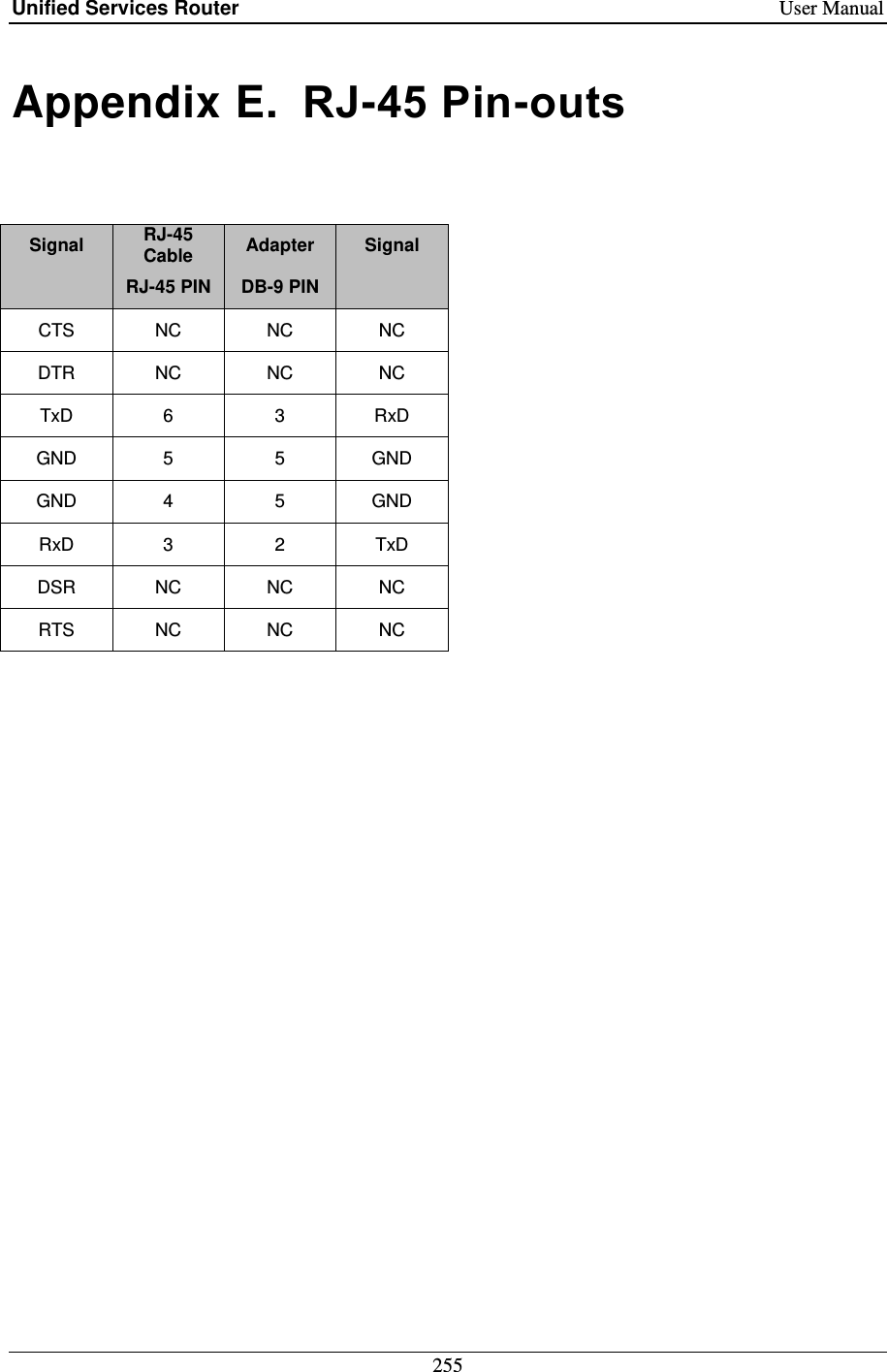
![Unified Services Router User Manual 258 [Czech] [D-- Dansk [Danish] Undertegnede [D-Link Corporation] erklærer herved, at følgende udstyr [DSR-1000N] overholder de væsentlige krav og øvrige relevante krav i direktiv 1999/5/EF. Deutsch [German] Hiermit erklärt [D-Link Corporation], dass sich das Gerät [DSR-1000N] in Übereinstimmung mit den grundlegenden Anforderungen und den übrigen einschlägigen Bestimmungen der Richtlinie 1999/5/EG befindet. Eesti [Estonian] Käesolevaga kinnitab [D-Link Corporation] seadme [DSR-1000N] vastavust direktiivi 1999/5/EÜ põhinõuetele ja nimetatud direktiivist tulenevatele teistele asjakohastele sätetele. English Hereby, [D-Link Corporation], declares that this [DSR-1000N] is in compliance with the essential requirements and other relevant provisions of Directive 1999/5/EC. Español [Spanish] Por medio de la presente [D-Link Corporation] declara que el [DSR-1000N] cumple con los requisitos esenciales y cualesquiera otras disposiciones aplicables o exigibles de la Directiva 1999/5/CE. [Greek] - -1000N] Français [French] Par la présente [D-Link Corporation] déclare que l'appareil [DSR-1000N] est conforme aux exigences essentielles et aux autres dispositions pertinentes de la directive 1999/5/CE. Italiano [Italian] Con la presente [D-Link Corporation] dichiara che questo [DSR-1000N] è conforme ai requisiti essenziali ed alle altre disposizioni pertinenti stabilite dalla direttiva 1999/5/CE. Latviski [Latvian] - - [Lithuanian] --1000N] atitinka esminius reikalavimus ir kitas 1999/5/EB Direktyvos nuostatas. Nederlands [Dutch] Hierbij verklaart [D-Link Corporation] dat het toestel [DSR-1000N] in overeenstemming is met de essentiële eisen en de andere relevante bepalingen van richtlijn 1999/5/EG. Malti [Maltese] Hawnhekk, [D-Link Corporation], jiddikjara li dan [DSR-1000N] jikkonforma mal--Dirrettiva 1999/5/EC. Magyar [Hungarian] Alulírott, [D-Link Corporation] nyilatkozom, hogy a [DSR-1000N] megfelel a vonatkozó alapvetõ követelményeknek és az 1999/5/EC irányelv egyéb elõírásainak. Polski [Polish] Niniejszym [D--1000N] jest zgodny z zasadniczymi /5/EC.](https://usermanual.wiki/D-Link/SR150NA1/User-Guide-1654819-Page-260.png)
![Unified Services Router User Manual 259 Português [Portuguese] [D-Link Corporation] declara que este [DSR-1000N]está conforme com os requisitos essenciais e outras disposições da Directiva 1999/5/CE. Slovensko [Slovenian] [D-Link Corporation] izjavlja, da je ta [DSR-1000N] v skladu z bistvenimi zahtevami in Slovensky [Slovak] [D- - Suomi [Finnish] [D-Link Corporation] vakuuttaa täten että [DSR-1000N] tyyppinen laite on direktiivin 1999/5/EY oleellisten vaatimusten ja sitä koskevien direktiivin muiden ehtojen mukainen. Svenska [Swedish] Härmed intygar [D-Link Corporation] att denna [DSR-1000N] står I överensstämmelse med de väsentliga egenskapskrav och övriga relevanta bestämmelser som framgår av direktiv 1999/5/EG.](https://usermanual.wiki/D-Link/SR150NA1/User-Guide-1654819-Page-261.png)
![Unified Services Router User Manual 262 [Czech] [D-Link CorporationDSR-500N Dansk [Danish] Undertegnede [D-Link Corporation] erklærer herved, at følgende udstyr [DSR-500N] overholder de væsentlige krav og øvrige relevante krav i direktiv 1999/5/EF. Deutsch [German] Hiermit erklärt [D-Link Corporation], dass sich das Gerät [DSR-500N] in Übereinstimmung mit den grundlegenden Anforderungen und den übrigen einschlägigen Bestimmungen der Richtlinie 1999/5/EG befindet. Eesti [Estonian] Käesolevaga kinnitab [D-Link Corporation] seadme [DSR-500N] vastavust direktiivi 1999/5/EÜ põhinõuetele ja nimetatud direktiivist tulenevatele teistele asjakohastele sätetele. English Hereby, [D-Link Corporation], declares that this [DSR-500N] is in compliance with the essential requirements and other relevant provisions of Directive 1999/5/EC. Español [Spanish] Por medio de la presente [D-Link Corporation] declara que el [DSR-500N] cumple con los requisitos esenciales y cualesquiera otras disposiciones aplicables o exigibles de la Directiva 1999/5/CE. [Greek] [D-Link Corporation [DSR-500N Français [French] Par la présente [D-Link Corporation] déclare que l'appareil [DSR-500N] est conforme aux exigences essentielles et aux autres dispositions pertinentes de la directive 1999/5/CE. Italiano [Italian] Con la presente [D-Link Corporation] dichiara che questo [DSR-500N] è conforme ai requisiti essenziali ed alle altre disposizioni pertinenti stabilite dalla direttiva 1999/5/CE. Latviski [Latvian] D-Link CorporationDSR-500N [Lithuanian] [D-Link CorporationDSR-500N] atitinka esminius reikalavimus ir kitas 1999/5/EB Direktyvos nuostatas. Nederlands [Dutch] Hierbij verklaart [D-Link Corporation] dat het toestel [DSR-500N] in overeenstemming is met de essentiële eisen en de andere relevante bepalingen van richtlijn 1999/5/EG. Malti [Maltese] Hawnhekk, [D-Link Corporation], jiddikjara li dan [DSR-500N] jikkonforma mal--Dirrettiva 1999/5/EC. Magyar [Hungarian] Alulírott, [D-Link Corporation] nyilatkozom, hogy a [DSR-500N] megfelel a vonatkozó alapvetõ követelményeknek és az 1999/5/EC irányelv egyéb elõírásainak. Polski [Polish] Niniejszym [D-Link CorporationDSR-500N] jest zgodny z zasadniczymi ](https://usermanual.wiki/D-Link/SR150NA1/User-Guide-1654819-Page-264.png)
![Unified Services Router User Manual 263 Português [Portuguese] [D-Link Corporation] declara que este [DSR-500N]está conforme com os requisitos essenciais e outras disposições da Directiva 1999/5/CE. Slovensko [Slovenian] [D-Link Corporation] izjavlja, da je ta [DSR-500N] v skladu z bistvenimi zahtevami in 1999/5/ES. Slovensky [Slovak] [D-Link CorporationDSR-500N Suomi [Finnish] [D-Link Corporation] vakuuttaa täten että [DSR-500N] tyyppinen laite on direktiivin 1999/5/EY oleellisten vaatimusten ja sitä koskevien direktiivin muiden ehtojen mukainen. Svenska [Swedish] Härmed intygar [D-Link Corporation] att denna [DSR-500N] står I överensstämmelse med de väsentliga egenskapskrav och övriga relevanta bestämmelser som framgår av direktiv 1999/5/EG.](https://usermanual.wiki/D-Link/SR150NA1/User-Guide-1654819-Page-265.png)
![Unified Services Router User Manual 264 3.DSR-250N Federal Communication Commission Interference Statement This equipment has been tested and found to comply with the limits for a Class B digital device, pursuant to Part 15 of the FCC Rules. These limits are designed to provide reasonable protection against harmful interference in a residential installation. This equipment generates, uses and can radiate radio frequency energy and, if not installed and used in accordance with the instructions, may cause harmful interference to radio communications. However, there is no guarantee that interference will not occur in a particular installation. If this equipment does cause harmful interference to radio or television reception, which can be determined by turning the equipment off and on, the user is encouraged to try to correct the interference by one of the following measures: Reorient or relocate the receiving antenna. Increase the separation between the equipment and receiver. Connect the equipment into an outlet on a circuit different from that to which the receiver is connected. Consult the dealer or an experienced radio/TV technician for help. FCC Caution: Any changes or modifications not expressly approved by the party responsible for compliance could void the user's authority to operate this equipment. This device complies with Part 15 of the FCC Rules. Operation is subject to the following two conditions: (1) This device may not cause harmful interference, and (2) this device must accept any interference received, including interference that may cause undesired operation. RSS-GEN 7.1.4: User Manual for Transmitters with Detachable Antennas The user manual of transmitter devices equipped with detachable antennas shall contain the following information in a conspicuous location: This device has been designed to operate with the antennas listed below, and having a maximum gain of [1.8] dB. Antennas not included in this list or having a gain greater than [1.8] dB are strictly prohibited for use with this device. The required antenna impedance is [50] ohms. RSS-GEN 7.1.5 To reduce potential radio interference to other users, the antenna type and its gain should be so chosen that the equivalent isotropically radiated power (e.i.r.p.) is not more than that permitted for successful communication. Le présent appareil est conforme aux CNR d'Industrie Canada applicables aux appareils radio exempts de licence. L'exploitation est autorisée aux deux conditions suivantes: (1) l'appareil ne doit pas produire de brouillage, et (2) l'utilisateur de l'appareil doit accepter tout brouillage radioélectrique subi, même si le brouillage est susceptible d'en comSpromettre le fonctionnement. Is herewith confirmed to comply with the requirements set out in the Council Directive on the Approximation of the Laws of the Member States relating to Electromagnetic Compatibility (2004/108/EC), Low-voltage Directive (2006/95/EC), the procedures given in European Council Directive 99/5/EC and 2004/104/EC. The equipment was passed. The test was performed according to the following European standards: EN 300 328 V.1.7.1 EN 301 489-1 V.1. 8.1 / EN 301 489-17 V.2.1.1 EN 62311 EN 60950-1](https://usermanual.wiki/D-Link/SR150NA1/User-Guide-1654819-Page-266.png)
![Unified Services Router User Manual 267 Electromagnetic compatibility and Radio Spectrum Matters (ERM); ElectroMagnetic Compatibility (EMC) standard for radio equipment and services; Part 1: Common technical requirements EN 301 489-17 V2.1.1 (2009-05) Electromagnetic compatibility and Radio spectrum Matters (ERM); ElectroMagnetic Compatibility (EMC) standard for radio equipment; Part 17: Specific conditions for Broadband Data Transmission Systems This device is a 2.4 GHz wideband transmission system (transceiver), intended for use in all EU member states and EFTA countries, except in France and Italy where restrictive use applies. In Italy the end-user should apply for a license at the national spectrum authorities in order to obtain authorization to use the device for setting up outdoor radio links and/or for supplying public access to telecommunications and/or network services. This device may not be used for setting up outdoor radio links in France and in some areas the RF output power may be limited to 10 mW EIRP in the frequency range of 2454 2483.5 MHz. For detailed information the end-user should contact the national spectrum authority in France. [Czech] Dansk [Danish] Undertegnede [fabrikantens navn] erklærer herved, at følgende udstyr [udstyrets typebetegnelse] overholder de væsentlige krav og øvrige relevante krav i direktiv 1999/5/EF. Deutsch [German] Hiermit erklärt [Name des Herstellers], dass sich das Gerät [Gerätetyp] in Übereinstimmung mit den grundlegenden Anforderungen und den übrigen einschlägigen Bestimmungen der Richtlinie 1999/5/EG befindet. Eesti [Estonian] Käesolevaga kinnitab [tootja nimi = name of manufacturer] seadme [seadme tüüp = type of equipment] vastavust direktiivi 1999/5/EÜ põhinõuetele ja nimetatud direktiivist tulenevatele teistele asjakohastele sätetele. English Hereby, [name of manufacturer], declares that this [type of equipment] is in compliance with the essential requirements and other relevant provisions of Directive 1999/5/EC. Español [Spanish] Por medio de la presente [nombre del fabricante] declara que el [clase de equipo] cumple con los requisitos esenciales y cualesquiera otras disposiciones aplicables o exigibles de la Directiva 1999/5/CE. [Greek] Français [French] Par la présente [nom du fabricant] déclare que l'appareil [type d'appareil] est conforme aux exigences essentielles et aux autres dispositions pertinentes de la directive 1999/5/CE. Italiano [Italian] Con la presente [nome del costruttore] dichiara che questo [tipo di apparecchio] è conforme ai requisiti essenziali ed alle altre disposizioni pertinenti stabilite dalla direttiva 1999/5/CE. Latviski [Latvian] / inoteikumiem. [Lithuanian] a esminius reikalavimus ir kitas 1999/5/EB Direktyvos nuostatas. Nederlands [Dutch] Hierbij verklaart [naam van de fabrikant] dat het toestel [type van toestel] in overeenstemming is met de essentiële eisen en de andere relevante bepalingen van richtlijn 1999/5/EG. Malti [Maltese] Hawnhekk, [isem tal-manifattur], jiddikjara li dan [il-mudel tal-prodott] jikkonforma mal--Dirrettiva 1999/5/EC. Magyar Alulírott, [gyártó neve] nyilatkozom, hogy a [... típus] megfelel a vonatkozó alapvetõ](https://usermanual.wiki/D-Link/SR150NA1/User-Guide-1654819-Page-269.png)
![Unified Services Router User Manual 268 [Hungarian] követelményeknek és az 1999/5/EC irányelv egyéb elõírásainak. Polski [Polish] ktywy 1999/5/EC. Português [Portuguese] [Nome do fabricante] declara que este [tipo de equipamento] está conforme com os requisitos essenciais e outras disposições da Directiva 1999/5/CE. Slovensko [Slovenian] [Ime proizvajalca] izjavlja, da je ta [tip opreme] v skladu z bistvenimi zahtevami in ostalimi Slovensky [Slovak] Suomi [Finnish] [Valmistaja = manufacturer] vakuuttaa täten että [type of equipment = laitteen tyyppimerkintä] tyyppinen laite on direktiivin 1999/5/EY oleellisten vaatimusten ja sitä koskevien direktiivin muiden ehtojen mukainen. Svenska [Swedish] Härmed intygar [företag] att denna [utrustningstyp] står I överensstämmelse med de väsentliga egenskapskrav och övriga relevanta bestämmelser som framgår av direktiv 1999/5/EG. Industry Canada statement: This device complies with RSS-210 of the Industry Canada Rules. Operation is subject to the following two conditions: (1) This device may not cause harmful interference, and (2) This device must accept any interference received, including interference that may cause undesired operation. Ce dispositif est conforme à la norme CNR-210 d'Industrie Canada applicable aux appareils radio exempts de licence. Son fonctionnement est sujet aux deux conditions suivantes: (1) le dispositif ne doit pas produire de brouillage préjudiciable, et (2) ce dispositif doit accepter tout brouillage reçu, y compris un brouillage susceptible de provoquer un fonctionnement indésirable. Radiation Exposure Statement: This equipment complies with IC radiation exposure limits set forth for an uncontrolled environment. This equipment should be installed and operated with minimum distance 20cm between the radiator & your body. Déclaration d'exposition aux radiations: Cet équipement est conforme aux limites d'exposition aux rayonnements IC établies pour un environnement non contrôlé. Cet équipement doit être installé et utilisé avec un minimum de 20 cm de distance entre la source de rayonnement et votre corps.](https://usermanual.wiki/D-Link/SR150NA1/User-Guide-1654819-Page-270.png)