D Link SR150NA1 802.11 bgn Service Router User Manual
D Link Corporation 802.11 bgn Service Router
D Link >
User Manual
Unified Services Router
User Manual
DSR-150 / 150N / 250 / 250N / 500 / 500N /
1000 / 1000N
Ver. 1.05
Building Networks for People
Small Business Gateway Solution


Unified Services Router User Manual
1
User Manual
DSR-150 / 150N /250 / 250N / DSR-500 / 500N / 1000 / 1000N
Unified Services Router
Version 1.05
Copyright © 2012
Copyright Notice
This publication, including all photographs, illustrations and software, is protected under
international copyright laws, with all rights reserved. N either this manual, nor any of the
material contained herein, may be reproduced without written consent of the author.
Disclaimer
The information in this document is subject to change without notice. The manufacturer makes
no representations or warranties with respect to the contents hereof and specifically disclaim
any implied warranties of merchantability or fitness for any particular purpose. The
manufacturer reserves the right to revise this publication and to make changes from time to
time in the content hereof without obligation of the manufacturer to notify any person of such
revision or changes.
Limitations of Liability
UNDER NO CIRCUMSTANCES SHALL D-LINK OR ITS SUPPLIERS BE LIABLE FOR
DAMAGES OF ANY CHARACTER (E.G. DAMAGES FOR LOSS OF PROFIT, SOFTW ARE
RESTORATION, WORK STOPPAGE, LOSS OF SAVED DATA OR ANY OTHER
COMMERCIAL DAMAGES OR LOSSES) RESULTING FROM THE APPLICATION OR
IMPROPER USE OF THE D-LINK PRODUCT OR FAILURE OF THE PRODUCT, EVEN IF
D-LINK IS INFORMED OF THE POSSIBILITY OF SUCH DAMAGES. FURTHERMORE, D-
LINK WILL NOT BE LIABLE FOR THIRD-PARTY CLAIMS AGAINST CUSTOMER FOR
LOSSES OR DAMAGES. D-LINK WILL IN NO EVENT BE LIABLE FOR ANY DAMAGES
IN EXCESS OF THE AMOUNT D-LINK RECEIVED FROM THE END-USER FOR THE
PRODUCT.

Unified Services Router User Manual
2
Table of Contents
Chapter 1. Introduction ........................................................................................................................... 11
1.1 About this User Manual .......................................................................................... 12
1.2 Typographical Conventions ................................................................................... 12
Chapter 2. Configuring Your Network: LAN Setup ............................................................................. 13
2.1 LAN Configuration................................................................................................... 13
2.1.1 LAN DHCP Reserved IPs ...................................................................................... 16
2.1.2 LAN DHCP Leased Clients.................................................................................... 17
2.1.3 LAN Configuration in an IPv6 Network ................................................................ 18
2.1.4 Configuring IPv6 Router Advertisements ............................................................ 21
2.2 VLAN Configuration ................................................................................................ 23
2.2.1 Associating VLANs to ports ................................................................................... 24
2.2.2 Multiple VLAN Subnets .......................................................................................... 26
2.2.3 VLAN configuration ................................................................................................. 27
2.3 Configurable Port: DMZ Setup .............................................................................. 28
2.4 Universal Plug and Play (UPnP) ........................................................................... 29
2.5 Captive Portal .......................................................................................................... 31
2.6 Captive portal setup ................................................................................................ 32
Chapter 3. Connecting to the Internet: WAN Setup ........................................................................... 35
3.1 Internet Setup Wizard ............................................................................................. 35
3.2 WAN Configuration ................................................................................................. 36
3.2.1 WAN Port IP address ............................................................................................. 37
3.2.2 WAN DNS Servers ................................................................................................. 37
3.2.3 DHCP WAN ............................................................................................................. 37
3.2.4 PPPoE ...................................................................................................................... 38
3.2.5 Russia L2TP and PPTP WAN ............................................................................... 41
3.2.6 Russia Dual Access PPPoE .................................................................................. 42
3.2.7 WAN Configuration in an IPv6 Network ............................................................... 43
3.2.8 Checking WAN Status ............................................................................................ 45
3.3 Bandwidth Controls................................................................................................. 47
3.4 Features with Multiple WAN Links ........................................................................ 49
3.4.1 Auto Failover ............................................................................................................ 49
3.4.2 Load Balancing ........................................................................................................ 50
3.4.3 Protocol Bindings .................................................................................................... 52
3.5 Routing Configuration ............................................................................................. 53
3.5.1 Routing Mode .......................................................................................................... 53
3.5.2 Dynamic Routing (RIP) .......................................................................................... 56
3.5.3 Static Routing .......................................................................................................... 57
3.5.4 OSPFv2 .................................................................................................................... 58
3.5.5 OSPFv3 .................................................................................................................... 60
3.5.6 6to4 Tunneling ......................................................................................................... 62
3.5.7 ISATAP Tunnels ...................................................................................................... 63
3.6 Configurable Port - WAN Option .......................................................................... 64
3.7 WAN 3 (3G) Configuration ..................................................................................... 64
3.8 WAN Port Settings .................................................................................................. 66

Unified Services Router User Manual
3
Chapter 4. Wireless Access Point Setup ............................................................................................. 68
4.1 Wireless Settings Wizard ....................................................................................... 68
4.1.1 Wireless Network Setup Wizard ........................................................................... 69
4.1.2 Add Wireless Device with WPS ............................................................................ 69
4.1.3 Manual Wireless Network Setup .......................................................................... 70
4.2 Wireless Profiles ..................................................................................................... 70
4.2.1 WEP Security .......................................................................................................... 71
4.2.2 WPA or WPA2 with PSK ........................................................................................ 73
4.2.3 RADIUS Authentication .......................................................................................... 73
4.3 Creating and Using Access Points ....................................................................... 75
4.3.1 Primary benefits of Virtual APs: ............................................................................ 77
4.4 Tuning Radio Specific Settings ............................................................................. 78
4.5 WMM ......................................................................................................................... 79
4.6 Wireless distribution system (WDS) ..................................................................... 80
4.7 Advanced Wireless Settings.................................................................................. 81
4.8 Wi-Fi Protected Setup (WPS) ............................................................................... 82
Chapter 5. Securing the Private Network ............................................................................................ 85
5.1 Firewall Rules .......................................................................................................... 85
5.2 Defining Rule Schedules ....................................................................................... 86
5.3 Configuring Firewall Rules ..................................................................................... 87
5.4 Configuring IPv6 Firewall Rules ............................................................................ 92
5.4.1 Firewall Rule Configuration Examples ................................................................. 93
5.5 Security on Custom Services ................................................................................ 97
5.6 ALG support ............................................................................................................. 99
5.7 VPN Passthrough for Firewall ............................................................................. 100
5.8 Application Rules .................................................................................................. 101
5.9 Web Content Filtering ........................................................................................... 102
5.9.1 Content Filtering .................................................................................................... 102
5.9.2 Approved URLs ..................................................................................................... 103
5.9.3 Blocked Keywords ................................................................................................ 104
5.9.4 Export Web Filter .................................................................................................. 105
5.10 IP/MAC Binding ..................................................................................................... 106
5.11 Intrusion Prevention (IPS).................................................................................... 107
5.12 Protecting from Internet Attacks ......................................................................... 108
Chapter 6. IPsec / PPTP / L2TP VPN ................................................................................................ 111
6.1 VPN Wizard ........................................................................................................... 113
6.2 Configuring IPsec Policies ................................................................................... 115
6.2.1 Extended Authentication (XAUTH) ..................................................................... 119
6.2.2 Internet over IPSec tunnel ................................................................................... 120
6.3 Configuring VPN clients ....................................................................................... 120
6.4 PPTP / L2TP Tunnels ........................................................................................... 120
6.4.1 PPTP Tunnel Support .......................................................................................... 120
6.4.2 L2TP Tunnel Support ........................................................................................... 122
6.4.3 OpenVPN Support ................................................................................................ 123
6.4.4 OpenVPN Remote Network ................................................................................ 125
6.4.5 OpenVPN Authentication ..................................................................................... 126

Unified Services Router User Manual
4
Chapter 7. SSL VPN ............................................................................................................................. 129
7.1 Groups and Users ................................................................................................. 131
7.1.1 Users and Passwords .......................................................................................... 137
7.2 Using SSL VPN Policies ...................................................................................... 138
7.2.1 Using Network Resources ................................................................................... 141
7.3 Application Port Forwarding ................................................................................ 142
7.4 SSL VPN Client Configuration ............................................................................ 144
7.5 User Portal ............................................................................................................. 147
7.5.1 Creating Portal Layouts ....................................................................................... 147
Chapter 8. Advanced Configuration Tools ......................................................................................... 150
8.1 USB Device Setup ................................................................................................ 150
8.2 USB share port ...................................................................................................... 151
8.3 SMS service ........................................................................................................... 153
8.4 Authentication Certificates ................................................................................... 154
8.5 Advanced Switch Configuration .......................................................................... 156
Chapter 9. Administration & Management ......................................................................................... 157
9.1 Configuration Access Control .............................................................................. 157
9.1.1 Admin Settings ...................................................................................................... 157
9.1.2 Remote Management ........................................................................................... 158
9.1.3 CLI Access ............................................................................................................. 159
9.2 SNMP Configuration ............................................................................................. 159
9.3 Configuring Time Zone and NTP ........................................................................ 161
9.4 Log Configuration .................................................................................................. 162
9.4.1 Defining What to Log ............................................................................................ 162
9.4.2 Sending Logs to E-mail or Syslog ...................................................................... 167
9.4.3 Event Log Viewer in GUI ..................................................................................... 169
9.5 Backing up and Restoring Configuration Settings ........................................... 170
9.6 Upgrading Router Firmware ................................................................................ 171
9.7 Upgrading Router Firmware via USB................................................................. 172
9.8 Dynamic DNS Setup ............................................................................................. 173
9.9 Using Diagnostic Tools ........................................................................................ 174
9.9.1 Ping ......................................................................................................................... 175
9.9.2 Trace Route ........................................................................................................... 175
9.9.3 DNS Lookup .......................................................................................................... 176
9.9.4 Router Options ...................................................................................................... 176
9.10 Localization ............................................................................................................ 177
Chapter 10. Router Status and Statistics ............................................................................................. 178
10.1 System Overview .................................................................................................. 178
10.1.1 Device Status ........................................................................................................ 178
10.1.2 Resource Utilization .............................................................................................. 180
10.2 Traffic Statistics ..................................................................................................... 183
10.2.1 Wired Port Statistics ............................................................................................. 183
10.2.2 Wireless Statistics ................................................................................................. 184
10.3 Active Connections ............................................................................................... 185
10.3.1 Sessions through the Router ............................................................................... 185

Unified Services Router User Manual
5
10.3.2 Wireless Clients..................................................................................................... 187
10.3.3 LAN Clients ............................................................................................................ 187
10.3.4 Active VPN Tunnels .............................................................................................. 188
Chapter 11. Trouble Shooting ................................................................................................................ 190
11.1 Internet connection ............................................................................................... 190
11.2 Date and time ........................................................................................................ 192
11.3 Pinging to Test LAN Connectivity ....................................................................... 192
11.3.1 Testing the LAN path from your PC to your router .......................................... 192
11.3.2 Testing the LAN path from your PC to a remote device ................................. 193
11.4 Restoring factory-default configuration settings ............................................... 194
Chapter 12. Credits ................................................................................................................................. 195
Appendix A. Glossary .............................................................................................................................. 196
Appendix B. Factory Default Settings ................................................................................................... 199
Appendix C. Standard Services Available for Port Forwarding & Firewall Configuration .............. 200
Appendix D. Log Output Reference ....................................................................................................... 201
Appendix E. RJ-45 Pin-outs .................................................................................................................... 255
Appendix F. Product Statement ............................................................................................................. 256

Unified Services Router User Manual
6
List of Figures
Figure 1: Setup page for LAN TCP/IP settings ...................................................................................... 15
Figure 2: LAN DHCP Reserved IPs ......................................................................................................... 17
Figure 3: LAN DHCP Leased Clients ...................................................................................................... 18
Figure 4: IPv6 LAN and DHCPv6 configuration ..................................................................................... 19
Figure 5: Configuring the Router Advertisement Daemon ................................................................... 22
Figure 6: IPv6 Advertisement Prefix settings ......................................................................................... 23
Figure 7: Adding VLAN memberships to the LAN ................................................................................. 24
Figure 8: Port VLAN list ............................................................................................................................. 25
Figure 9: Configuring VLAN membership for a port .............................................................................. 26
Figure 10: Multiple VLAN Subnets ........................................................................................................... 27
Figure 11: VLAN Configuration ................................................................................................................. 28
Figure 12: DMZ configuration ................................................................................................................... 29
Figure 13: UPnP Configuration ................................................................................................................. 30
Figure 14: Active Runtime sessions ........................................................................................................ 32
Figure 15: Captive Portal Setup ............................................................................................................... 33
Figure 16: Customized Captive Portal Setup ......................................................................................... 34
Figure 17: Internet Connection Setup Wizard ........................................................................................ 35
Figure 18: Manual WAN configuration..................................................................................................... 38
Figure 19: PPPoE configuration for standard ISPs ............................................................................... 39
Figure 20: WAN configuration for Japanese Multiple PPPoE (part 1) ................................................ 40
Figure 21: WAN configuration for Multiple PPPoE (part 2) .................................................................. 41
Figure 22: Russia L2TP ISP configuration .............................................................................................. 42
Figure 23: Russia Dual access PPPoE configuration ........................................................................... 43
Figure 24: IPv6 WAN Setup page ............................................................................................................ 44
Figure 25: Connection Status information for both WAN ports ............................................................ 46
Figure 26: List of Configured Bandwidth Profiles ................................................................................... 47
Figure 27: Bandwidth Profile Configuration page .................................................................................. 48
Figure 28: Traffic Selector Configuration ................................................................................................ 49
Figure 29: Load Balancing is available when multiple WAN ports are configured and Protocol
Bindings have been defined ................................................................................................... 52
Figure 30: Protocol binding setup to associate a service and/or LAN source to a WAN and/or
destination network .................................................................................................................. 53
Figure 31: Routing Mode is used to configure traffic routing between WAN and LAN, as well as
Dynamic routing (RIP) ............................................................................................................. 55
Figure 32: Static route configuration fields ............................................................................................. 58

Unified Services Router User Manual
7
Figure 33: OSPFv2 configured parameters ............................................................................................ 59
Figure 34: OSPFv2 configuration ............................................................................................................. 60
Figure 35: OSPFv3 configured parameters ............................................................................................ 61
Figure 36: OSPFv3 configuration ............................................................................................................. 62
Figure 37: 6 to 4 tunneling ......................................................................................................................... 63
Figure 38: ISATAP Tunnels Configuration .............................................................................................. 64
Figure 39: WAN3 configuration for 3G internet ...................................................................................... 66
Figure 40: Physical WAN port settings .................................................................................................... 67
Figure 41: Wireless Network Setup Wizards .......................................................................................... 69
Figure 42: List of Available Profiles shows the options available to secure the wireless link ......... 71
Figure 43: Profile configuration to set network security ........................................................................ 73
Figure 44: RADIUS server (External Authentication) configuration .................................................... 75
Figure 45: Virtual AP configuration .......................................................................................................... 76
Figure 46: List of configured access points (Virtual APs) shows one enabled access point on the
radio, broadcasting its SSID ................................................................................................... 77
Figure 47: Radio card configuration options ........................................................................................... 78
Figure 48: Wi-Fi Multimedia ...................................................................................................................... 79
Figure 49: Wireless Distribution System ................................................................................................. 80
Figure 50: Advanced Wireless communication settings ....................................................................... 82
Figure 51: WPS configuration for an AP with WPA/WPA2 profile ....................................................... 83
Figure 52: List of Available Firewall Rules .............................................................................................. 86
Figure 53: List of Available Schedules to bind to a firewall rule .......................................................... 87
Figure 54: Example where an outbound SNAT rule is used to map an external IP address
(209.156.200.225) to a private DMZ IP address (10.30.30.30) ........................................ 90
Figure 55: The firewall rule configuration page allows you to define the To/From zone, service,
action, schedules, and specify source/destination IP addresses as needed. ................. 91
Figure 56: The IPv6 firewall rule configuration page allows you to define the To/From zone,
service, action, schedules, and specify source/destination IP addresses as needed. .. 92
Figure 57: List of Available IPv6 Firewall Rules ..................................................................................... 93
Figure 58: Schedule configuration for the above example. .................................................................. 96
Figure 59: List of user defined services. ................................................................................................. 98
Figure 60: Custom Services configuration .............................................................................................. 98
Figure 61: Available ALG support on the router................................................................................... 100
Figure 62: Passthrough options for VPN tunnels ................................................................................. 101
Figure 63: List of Available Application Rules showing 4 unique rules ............................................ 102
Figure 64: Content Filtering used to block access to proxy servers and prevent ActiveX controls
from being downloaded ......................................................................................................... 103

Unified Services Router User Manual
8
Figure 65: Two trusted domains added to the Approved URLs List ................................................. 104
Figure 66: One keyword added to the block list ................................................................................... 105
Figure 67: Export Approved URL list ..................................................................................................... 106
Figure 68: The following example binds a LAN host’s MAC Address to an IP address served by
DSR. If there is an IP/MAC Binding violation, the violating packet will be dropped and
logs will be captured .............................................................................................................. 107
Figure 69: Intrusion Prevention features on the router ....................................................................... 108
Figure 70: Protecting the router and LAN from internet attacks ........................................................ 109
Figure 71: Example of Gateway-to-Gateway IPsec VPN tunnel using two DSR routers connected
to the Internet .......................................................................................................................... 111
Figure 72: Example of three IPsec client connections to the internal network through the DSR
IPsec gateway ........................................................................................................................ 112
Figure 73: VPN Wizard launch screen .................................................................................................. 113
Figure 74: IPsec policy configuration ..................................................................................................... 116
Figure 75: IPsec policy configuration continued (Auto policy via IKE).............................................. 117
Figure 76: IPsec policy configuration continued (Auto / Manual Phase 2) ...................................... 119
Figure 77: PPTP tunnel configuration – PPTP Client .......................................................................... 121
Figure 78: PPTP VPN connection status .............................................................................................. 121
Figure 79: PPTP tunnel configuration – PPTP Server ........................................................................ 122
Figure 80: L2TP tunnel configuration – L2TP Server .......................................................................... 123
Figure 81: OpenVPN configuration ........................................................................................................ 125
Figure 82: OpenVPN Remote Network ................................................................................................. 126
Figure 83: OpenVPN Authentication ...................................................................................................... 127
Figure 84: Example of clientless SSL VPN connections to the DSR ................................................ 130
Figure 85: List of groups .......................................................................................................................... 131
Figure 86: User group configuration ...................................................................................................... 132
Figure 87: SSLVPN Settings ................................................................................................................... 133
Figure 88: Group login policies options ................................................................................................. 134
Figure 89: Browser policies options ....................................................................................................... 135
Figure 90: IP policies options .................................................................................................................. 136
Figure 91: Available Users with login status and associated Group ................................................. 137
Figure 92: User configuration options .................................................................................................... 138
Figure 93: List of SSL VPN polices (Global filter) ................................................................................ 139
Figure 94: SSL VPN policy configuration .............................................................................................. 140
Figure 95: List of configured resources, which are available to assign to SSL VPN policies ....... 142
Figure 96: List of Available Applications for SSL Port Forwarding .................................................... 144
Figure 97: SSL VPN client adapter and access configuration ........................................................... 145

Unified Services Router User Manual
9
Figure 98: Configured client routes only apply in split tunnel mode ................................................. 146
Figure 99: List of configured SSL VPN portals. The configured portal can then be associated with
an authentication domain ...................................................................................................... 147
Figure 100: SSL VPN Portal configuration ........................................................................................... 149
Figure 101: USB Device Detection ........................................................................................................ 151
Figure 102: USB SharePort .................................................................................................................... 152
Figure 103: SMS Service – Send SMS ................................................................................................. 153
Figure 104: SMS Service – Receive SMS ............................................................................................ 154
Figure 105: Certificate summary for IPsec and HTTPS management ............................................. 155
Figure 106: Advanced Switch Settings .................................................................................................. 156
Figure 107: User Login policy configuration ......................................................................................... 157
Figure 108: Admin Settings ..................................................................................................................... 158
Figure 109: Remote Management from the WAN ............................................................................... 159
Figure 110: SNMP Users, Traps, and Access Control ........................................................................ 160
Figure 111: SNMP system information for this router ......................................................................... 161
Figure 112: Date, Time, and NTP server setup ................................................................................... 162
Figure 113: Facility settings for Logging ............................................................................................... 164
Figure 114: Log configuration options for traffic through router ......................................................... 166
Figure 115: IPv6 Log configuration options for traffic through router ................................................ 167
Figure 116: E-mail configuration as a Remote Logging option .......................................................... 168
Figure 117: Syslog server configuration for Remote Logging (continued) ....................................... 169
Figure 118: VPN logs displayed in GUI event viewer ......................................................................... 170
Figure 119: Restoring configuration from a saved file will result in the current configuration being
overwritten and a reboot ....................................................................................................... 171
Figure 120: Firmware version information and upgrade option ......................................................... 172
Figure 121: Firmware upgrade and configuration restore/backup via USB ..................................... 173
Figure 122: Dynamic DNS configuration ............................................................................................... 174
Figure 123: Router diagnostics tools available in the GUI ................................................................. 175
Figure 124: Sample trace route output .................................................................................................. 176
Figure 125: Localization........................................................................................................................... 177
Figure 126: Device Status display .......................................................................................................... 179
Figure 127: Device Status display (continued) ..................................................................................... 180
Figure 128: Resource Utilization statistics ............................................................................................ 181
Figure 129: Resource Utilization data (continued) .............................................................................. 182
Figure 130: Resource Utilization data (continued) .............................................................................. 183
Figure 131: Physical port statistics ........................................................................................................ 184

Unified Services Router User Manual
10
Figure 132: AP specific statistics ............................................................................................................ 185
Figure 133: List of current Active Firewall Sessions............................................................................ 186
Figure 134: List of connected 802.11 clients per AP ........................................................................... 187
Figure 135: List of LAN hosts ................................................................................................................. 188
Figure 136: List of current Active VPN Sessions ................................................................................. 189

Unified Services Router User Manual
11
Chapter 1. Introduction
D-Link Unified Services Routers offer a secure, high performance networking solution
to address the growing needs of small and medium businesses. Integrated high -speed
IEEE 802.11n and 3G wireless technologies offer compara ble performance to
traditional wired networks, but with fewer limitations. Optimal network security is
provided via features such as virtual private network (VPN) tunnels, IP Security
(IPsec), Point-to-Point Tunneling Protocol (PPTP), Layer 2 Tunneling Pro tocol (L2TP),
and Secure Sockets Layer (SSL). Empower your road warriors with clientless remote
access anywhere and anytime using SSL VPN tunnels.
With the D-Link Unified Services Router you are able to experience a diverse set of
benefits:
Comprehensive Management Capabilities
The DSR-500, DSR-500N, DSR-1000 and DSR-1000N include dual-WAN
Gigabit Ethernet which provides policy-based service management ensuring
maximum productivity for your business operations. The failover feature
maintains data traffic without disconnecting when a landline connection is lost.
The Outbound Load Balancing feature adjusts outgoing traffic across two WAN
interfaces and optimizes the system performance resulting in high availability.
The second WAN port can be configured as a DMZ port allowing you to isolate
servers from your LAN.
DSR-150/150N/250 /250N have a single WAN interface, and thus it does not
support Auto Failover and Load Balancing scenarios.
Superior Wireless Performance
Designed to deliver superior wireless performance, the DSR-500N and DSR-
1000N include 802.11 a/b/g/n, allowing for operation on either the 2.4 GHz or
5 GHz radio bands. Multiple In Multiple Out (MIMO) technology allows the
DSR-500N and DSR-1000N to provide high data rates with minimal “dead
spots” throughout the wireless coverage area.
DSR-150N, 250N and DSR-500N supports the 2.4GHz radio band only.
Flexible Deployment Options
The DSR-1000 / 1000N supports Third Generation (3G) Networks via an
extendable USB 3G dongle. This 3G network capability offer s an additional
secure data connection for networks that provide critical services. The DSR -
1000N can be configured to automatically switch to a 3G network whenever a
physical link is lost.
Robust VPN features
A fully featured virtual private network (VPN) provides your mobile workers
and branch offices with a secure link to your network. The DSR-
150/150N/250/250N, DSR-500/500N and DSR-1000 /1000N are capable of
simultaneously managing 5, 5, 10, 20 Secure Sockets Layer (SSL) VPN tunnels
respectively, empowering your mobile users by providing remote access to a

Unified Services Router User Manual
12
central corporate database. Site-to-site VPN tunnels use IP Security (IPsec)
Protocol, Point-to-Point Tunneling Protocol (PPTP), or Layer 2 Tunneling
Protocol (L2TP) to facilitate branch office connectivity through encrypted
virtual links. The DSR-150/150N, DSR-250/250N, DSR-500/500N and DSR-
1000/1000N support 10, 25, 35 and 75 simultaneous IPSec VPN tunnels
respectively.
Efficient D-Link Green Technology
As a concerned member of the global community, D -Link is devoted to
providing eco-friendly products. D-Link Green WiFi and D-Link Green
Ethernet save power and prevent waste. The D-Link Green WLAN scheduler
reduces wireless power automatically during off -peak hours. Likewise the D -
Link Green Ethernet program adjusts power usage based on the detected cable
length and link status. In addition, compliance with RoHS (Restriction of
Hazardous Substances) and WEEE (Waste Electrical and Electronic Equipment)
directives make D-Link Green certified devices the environmentally responsible
choice.
Support for the 3G wireless WAN USB dongle is only available for DSR-1000 and
DSR-1000N.
1.1 About this User Manual
This document is a high level manual to allow new D-Link Unified Services Router
users to configure connectivity, setup VPN tunnels, establish firewall rules and
perform general administrative tasks. Typical deployment and use case scenarios are
described in each section. For more detailed setup instructions and explanations of
each configuration parameter, refer to the online help that can be accessed from each
page in the router GUI.
1.2 Typographical Conventions
The following is a list of the various terms, followed by an example of how that term
is represented in this document:
Product Name – D-Link Unified Services Router.
o Model numbers DSR-500/500N/1000/1000N/250/250N/150/150N
GUI Menu Path/GUI Navigation – Monitoring > Router Status
Important note –

Chapter 2. Configuring Your Network:
LAN Setup
It is assumed that the user has a machine for management connected to the LAN to the
router. The LAN connection may be through the wired Ethernet ports available on the
router, or once the initial setup is complete, the DSR may also be managed through its
wireless interface as it is bridged with the LAN. Access the router’s graphical user
interface (GUI) for management by using any web browser, such as Microsoft Internet
Explorer or Mozilla Firefox:
Go to http://192.168.10.1 (default IP address) to display the router’s
management login screen.
Default login credentials for the ma nagement GUI:
Username: admin
Password: admin
If the router’s LAN IP address was changed, use that IP address in the navigation
bar of the browser to access the router’s management UI.
2.1 LAN Configuration
Setup > Network Settings > LAN Configuration
By default, the router functions as a Dynamic Host Configuration Protocol (DHCP)
server to the hosts on the WLAN or LAN network. With DHCP, PCs and other LAN
devices can be assigned IP addresses as well as addresses for DNS servers, Windows
Internet Name Service (WINS) servers, and the default gateway. With the DHCP
server enabled the router’s IP address serves as the gateway address for LAN and
WLAN clients. The PCs in the LAN are assigned IP addresses from a pool of
addresses specified in this procedure. Each poo l address is tested before it is assigned
to avoid duplicate addresses on the LAN.
For most applications the default DHCP and TCP/IP settings are satisfactory. If you
want another PC on your network to be the DHCP server or if you are manually
configuring the network settings of all of your PCs, set the DHCP mode to ‘none’.
DHCP relay can be used to forward DHCP lease information from another LAN
device that is the network’s DHCP server; this is particularly useful for wireless
clients.
Instead of using a DNS server, you can use a Windows Internet Naming Service
(WINS) server. A WINS server is the equivalent of a DNS server but uses the
NetBIOS protocol to resolve hostnames. The router includes the WINS server IP
address in the DHCP configuration when acknowledging a DHCP request from a
DHCP client.
You can also enable DNS proxy for the LAN. When this is enabled the router then as
a proxy for all DNS requests and communicates with the ISP’s DNS servers. When
disabled all DHCP clients receive the DNS IP addresses of the ISP.

Unified Services Router User Manual
14
To configure LAN Connectivity, please follow the steps below:
1. In the LAN Setup page, enter the following information for your router:
IP address (factory default: 192.168.10.1).
If you change the IP address and click Save Settings, the GUI will not respond.
Open a new connection to the new IP address and log in again. Be sure the LAN
host (the machine used to manage the router) has obtained IP address from newly
assigned pool (or has a static IP address in the router’s LAN subnet) before
accessing the router via changed IP address.
Subnet mask (factory default: 255.255.255.0).
2. In the DHCP section, select the DHCP mode:
None: the router’s DHCP server is disabled for the LAN
DHCP Server. With this option the router assigns an IP address within the
specified range plus additional specified information to any LAN device
that requests DHCP served addresses.
DHCP Relay: With this option enabled, DHCP clients on the LAN can
receive IP address leases and corresponding information from a DHCP
server on a different subnet. Specify the Relay Gateway, and when LAN
clients make a DHCP request it will be passed along to the server
accessible via the Relay Gateway IP address.
If DHCP is being enabled, enter the following DHCP server parameters:
Starting and Ending IP Addresses: Enter the first and last continuous
addresses in the IP address pool. Any new DHCP client joining the LAN is
assigned an IP address in this range. The default starting address is
192.168.10.2. The default ending address is 192.168.10.100. These
addresses should be in the same IP address subnet as the router’s LAN IP
address. You may wish to save part of the subnet range for devices with
statically assigned IP addresses in the LAN .
Primary and Secondary DNS servers: If configured domain name system
(DNS) servers are available on the LAN enter their IP addresses here.
WINS Server (optional): Enter the IP address for the WINS server or, if
present in your network, the Windows NetBios server.
Unified Services Router User Manual
15
Lease Time: Enter the time, in hours, for which IP addresses are leased to
clients.
Relay Gateway: Enter the gateway address. This is the only configuration
parameter required in this section when DHCP Relay is selected as its
DHCP mode
3. In the DNS Host Name Mapping section:
Host Name: Provide a valid host name
IP address: Provide the IP address of the host name,
4. In the LAN proxy section:
Enable DNS Proxy: To enable the router to act as a proxy for all DNS
requests and communicate with the ISP’s DNS servers, click the checkbox.
5. Click Save Settings to apply all changes.
Figure 1: Setup page f or LAN TCP/ IP settings

Unified Services Router User Manual
16
2.1.1 LAN DHCP Reserved IPs
Setup > Network Settings > LAN DHCP Reserved IPs
This router DHCP server can assign TCP/IP configurations to computers in the LAN
explicitly by adding client's network interface hardware address and the IP address to
be assigned to that client in DHCP server's database. Whenever DHCP server receives
a request from client, hardware address of that client is compared with the hardware
address list present in the database, if an IP address is already assigned to that
computer or device in the database , the customized IP address is configured
otherwise an IP address is assigned to the client automatically from the DHCP pool.
Computer Name: The user defined name for the LAN host.
IP Addresses: The LAN IP address of a host that is reserved by the DHCP server.
MAC Addresses: The MAC address that will be assigned the reserved IP address
when it is on the LAN.
Associate with IP/MAC Binding: When the user enables this option the Computer
Name, IP and MAC addresses are associated with the IP/MAC binding.
The actions that can be taken on list of reserved IP addresses are:
Select: Selects all the reserved IP addresses in the list.
Edit: Opens the LAN DHCP Reserved IP Configuration page to edit the selected
binding rule.
Delete: Deletes the selected IP address reservation(s)
Add: Opens the LAN DHCP Reserved IP Configuration page to add a new binding
rule.
Unified Services Router User Manual
17
Figure 2: LAN DHCP Reserved IPs
2.1.2 LAN DHCP Leased Clients
Setup > Network Settings > LAN DHCP Leased Clients
This page provides the list of clients connect to LAN DHCP server.
Unified Services Router User Manual
18
Figure 3: LAN DHCP Lease d Clients
IP Addresses: The LAN IP address of a host that matches the reserved IP list.
MAC Addresses: The MAC address of a LAN host that has a configured IP address
reservation.
2.1.3 LAN Configuration in an IPv6 Network
Advanced > IPv6 > IPv6 LAN > IPv6 LAN Config
(1) In IPv6 mode, the LAN DHCP server is enabled by default (similar to IPv4
mode). The DHCPv6 server will serve IPv6 addresses from configured address
pools with the IPv6 Prefix Length assigned to the LAN.
IPv4 / IPv6 mode must be enabled in the Advanced > IPv6 > IP mode to enable
IPv6 configuration options.
LAN Settings
The default IPv6 LAN address for the router is fec0::1. You can change this 128 bit
IPv6 address based on your network requirements. The other field that defines the
LAN settings for the router is the prefix length. The IPv6 network (subnet) is
identified by the initial bits of the address called the prefix. By default this is 64
bits long. All hosts in the network have common initial bits for their IPv6 address;
the number of common initial bits in the network’s addresses is set by the pr efix
length field.
Unified Services Router User Manual
19
Figure 4: IPv6 LAN and DH CPv6 conf iguration
If you change the IP address and click Save Settings, the GUI will not respond.
Open a new connection to the new IP address and log in again. Be sure the LAN
host (the machine used to manage the router) has obtained IP address from newly
assigned pool (or has a static IP address in the router’s LAN subnet) before
accessing the router via changed IP address.

Unified Services Router User Manual
20
As with an IPv4 LAN network, the router has a DHCPv6 server. If enabled, the
router assigns an IP address within the specified range plus additional specified
information to any LAN PC that requests DHCP served addresses.
The following settings are used to configure the DHCPv6 server:
DHCP Mode: The IPv6 DHCP server is either stateless or stateful. If stateless is
selected an external IPv6 DHCP server is not required as the IPv6 LAN hosts
are auto-configured by this router. In this case the router advertisement daemon
(RADVD) must be configured on this device and I CMPv6 router discovery
messages are used by the host for auto-configuration. There are no managed
addresses to serve the LAN nodes. If stateful is selected the IPv6 LAN host will
rely on an external DHCPv6 server to provide required configuration settings
The domain name of the DHCPv6 server is an optional setting
Server Preference is used to indicate the preference level of this DHCP server.
DHCP advertise messages with the highest server preference value to a LAN
host are preferred over other DHCP server advertise messages. The default is
255.
The DNS server details can be manually entered here (primary/secondary
options. An alternative is to allow the LAN DHCP client to receive the DNS
server details from the ISP directly. By selecting Use DNS proxy, this router
acts as a proxy for all DNS requests and communicates with the ISP’s DNS
servers (a WAN configuration parameter).
Primary and Secondary DNS servers: If there is configured domain name
system (DNS) servers available on the LAN enter the IP addresses here.
Lease/Rebind time sets the duration of the DHCPv6 lease from this router to the
LAN client.
IPv6 Address Pools
This feature allows you to define the IPv6 delegation prefix for a range of IP
addresses to be served by the gateway’s DHCPv6 server . Using a delegation prefix
you can automate the process of informing other networking equipment on the LAN
of DHCP information specific for the assigned prefix.
Prefix Delegation
The following settings are used to configure the Prefix Delegation:
Prefix Delegation: Select this option to enable prefix delegation in DHCPv6
server. This option can be selected only in Stateless Address Auto
Configuration mode of DHCPv6 server.

Unified Services Router User Manual
21
Prefix Address: IPv6 prefix address in the DHCPv6 server prefix pool
Prefix Length: Length prefix address
2.1.4 Configuring IPv6 Router Advertisements
Router Advertisements are analogous to IPv4 DHCP assignments for LAN clients, in
that the router will assign an IP address and supporting network information to
devices that are configured to accept s uch details. Router Advertisement is required
in an IPv6 network is required for stateless auto configuration of the IPv6 LAN. By
configuring the Router Advertisement Daemon on this router, the DSR will listen on
the LAN for router solicitations and respond to these LAN hosts with router
advisements.
RADVD
Advanced > IPv6 > IPv6 LAN > Router Advertisement
To support stateless IPv6 auto configuration on the LAN, set the RADVD status to
Enable. The following settings are used to configure RADVD:
Advertise Mode: Select Unsolicited Multicast to send router advertisements
(RA’s) to all interfaces in the multicast group. To restrict RA’s to well-
known IPv6 addresses on the LAN, and thereby reduce overall network
traffic, select Unicast only.
Advertise Interval: When advertisements are unsolicited multicast packets,
this interval sets the maximum time between advertisements from the
interface. The actual duration between advertisements is a random value
between one third of this field and this field. The default is 30 seconds.
RA Flags: The router advertisements (RA’s) can be sent with one or both of
these flags. Chose Managed to use the administered /sta teful protocol for
address auto configuration. If the Other flag is selected the host uses
administered/stateful protocol for non-address auto configuration.
Router Preference: this low/medium/high parameter determines the
preference associated with the RADVD process of the router. This is useful
if there are other RADVD enabled devices on the LAN as it helps avoid
conflicts for IPv6 clients.
MTU: The router advertisement will set this maximum transmission unit
(MTU) value for all nodes in the LAN that are auto configured by the router.
The default is 1500.
Router Lifetime: This value is present in RA’s and indicates the usefulness
of this router as a default router for the interface. The default is 3600
Unified Services Router User Manual
22
seconds. Upon expiration of this value, a new RADVD exchange must take
place between the host and this router.
Figure 5: Configuring the Router Advertisement Dae mon
Advertisement Prefixes
Advanced > IPv6 > IPv6 LAN > Advertisement Prefixes
The router advertisements configured with advertisement prefixes allow this router
to inform hosts how to perform stateless address auto configuration. Router
advertisements contain a list of subnet prefixes that allow the router to determine
neighbours and whether the host is on the same link as the router .
The following prefix options are available for the router advertisements:
IPv6 Prefix Type: To ensure hosts support IPv6 to IPv4 tunnel select the
6to4 prefix type. Selecting Global/Local/ISATAP will allow the nodes to
support all other IPv6 routing options
SLA ID: The SLA ID (Site-Level Aggregation Identifier) is available when
6to4 Prefixes are selected. This should be the interface ID of the router’s
LAN interface used for router advertisements.
Unified Services Router User Manual
23
IPv6 Prefix: When using Global/Local/ISATAP prefixes, this field is used to
define the IPv6 network advertised by this router.
IPv6 Prefix Length: This value indicates the number contiguous, higher
order bits of the IPv6 address that define up the network portion of the
address. Typically this is 64.
Prefix Lifetime: This defines the duration (in seconds) that the requesting
node is allowed to use the advertised prefix. It is analogous to DHCP lease
time in an IPv4 network.
Figure 6: IPv6 Advertisement Prefix settings
2.2 VLAN Configuration
The router supports virtual network isolation on the LAN with the use of VLANs.
LAN devices can be configured to communicate in a sub network defined by VLAN
identifiers. LAN ports can be assigned unique VLAN IDs so that traffic to and from
that physical port can be isolated from the general LAN. VLAN filtering is
particularly useful to limit broadcast packets of a device in a large network
VLAN support is disabled by default in the router. In the VLAN Configuration page,
enable VLAN support on the router and then proceed to the next section to define the
virtual network.
Setup > VLAN Settings > Available VLAN
The Available VLAN page shows a list of configured VLANs by name and VLAN ID.
A VLAN membership can be created by clicking the Add button below the List of
Available VLANs.
A VLAN membership entry consists of a VLAN identifier and the numerical VLAN
ID which is assigned to the VLAN membership. The VLAN ID value can be any
Unified Services Router User Manual
24
number from 2 to 4091. VLAN ID 1 is reserved for the default VLAN, which is used
for untagged frames received on the interface. By enabling Inter VLAN Routing, you
will allow traffic from LAN hosts belonging to this VLAN ID to pass through to other
configured VLAN IDs that have Inter VLAN Routing enabled.
Figure 7: Addi ng VLAN member ships to the LAN
2.2.1 Associating VLANs to ports
In order to tag all traffic through a specific LAN port with a VLAN ID, you can
associate a VLAN to a physical port.
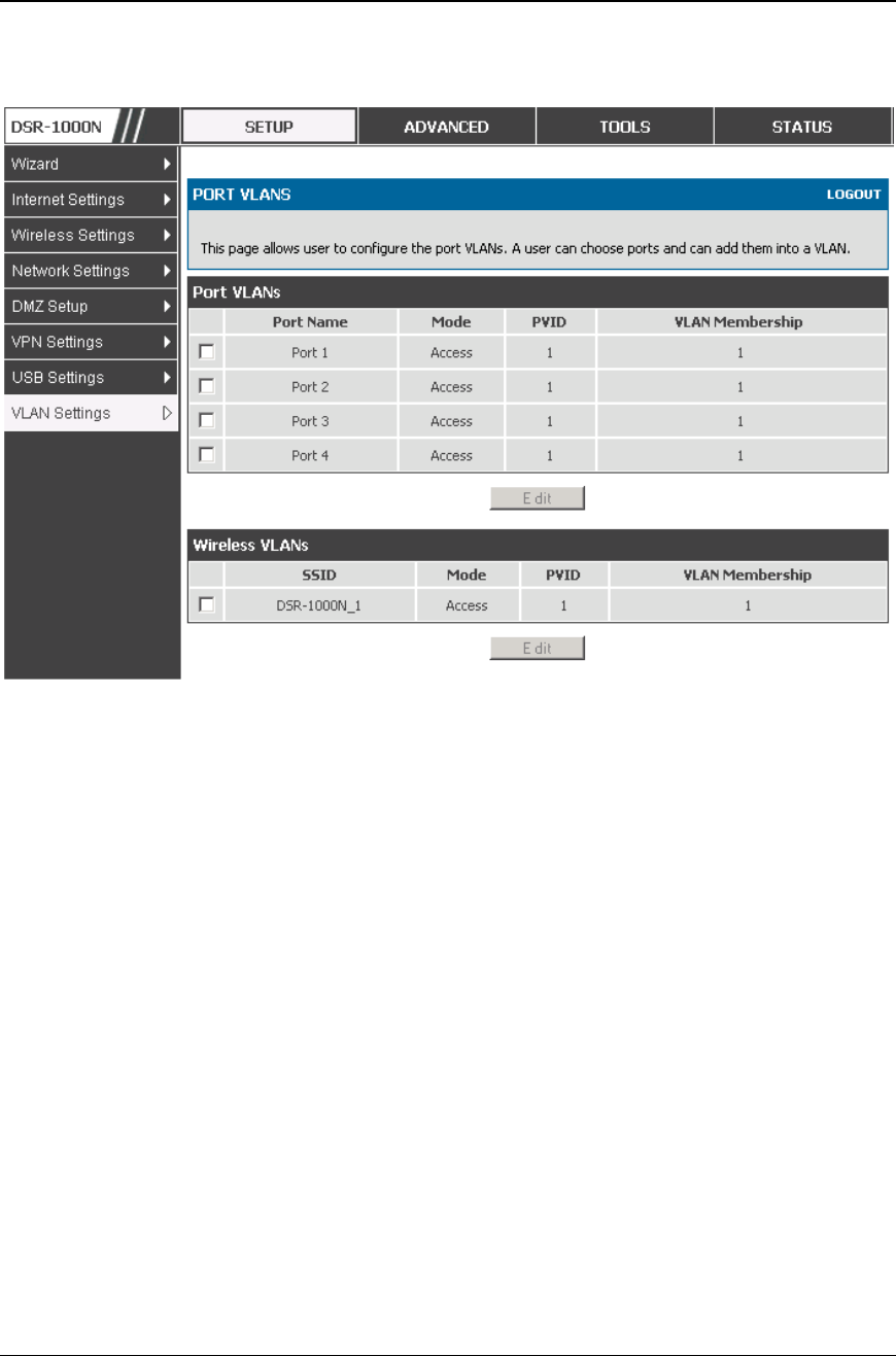
Setup > VLAN Settings > Port VLAN
VLAN membership properties for the LAN and wireless LAN are listed on this page.
The VLAN Port table displays the port identifier, the mode setting for that port and
VLAN membership information. The configuration page is accessed by selecting
one of the four physical ports or a configured access point and clicking Edit.
The edit page offers the following configuration options:
Mode: The mode of this VLAN can be General, Access, or Trunk. The
default is access.
In General mode the port is a member of a user selectable set of VLANs.
The port sends and receives data that is tagged or untagged with a VLAN
ID. If the data into the port is untagged, it is assigned the defined PVID. In
the configuration from Figure 4, Port 3 is a General port with PVID 3, so
untagged data into Port 3 will be assigned PVID 3. All tagged data sent out
of the port with the same PVID will be untagged. This is mode is typically
used with IP Phones that have dual Ethernet ports. Data coming from phone
to the switch port on the router will be tagged. Data passing through the
phone from a connected device will be untagged.
Unified Services Router User Manual
25
Figure 8: Port VLAN list
In Access mode the port is a member of a single VLAN (and only one). All
data going into and out of the port is untagged. Traffic through a port in
access mode looks like any other Ethernet frame.
In Trunk mode the port is a member of a user selectable set of VLANs. All
data going into and out of the port is tagged. Untagged coming into the port
is not forwarded, except for the default VLAN with PVID=1, which is
untagged. Trunk ports multiplex traffic for multiple VLANs over the same
physical link.
Select PVID for the port when the General mode is selected.
Configured VLAN memberships will be displayed on the VLAN
Membership Configuration for the port. By selecting one more VLAN
membership options for a General or Trunk port, traffic can be route d
between the selected VLAN membership IDs
Unified Services Router User Manual
26
Figure 9: Configuring VLAN me mbership for a port
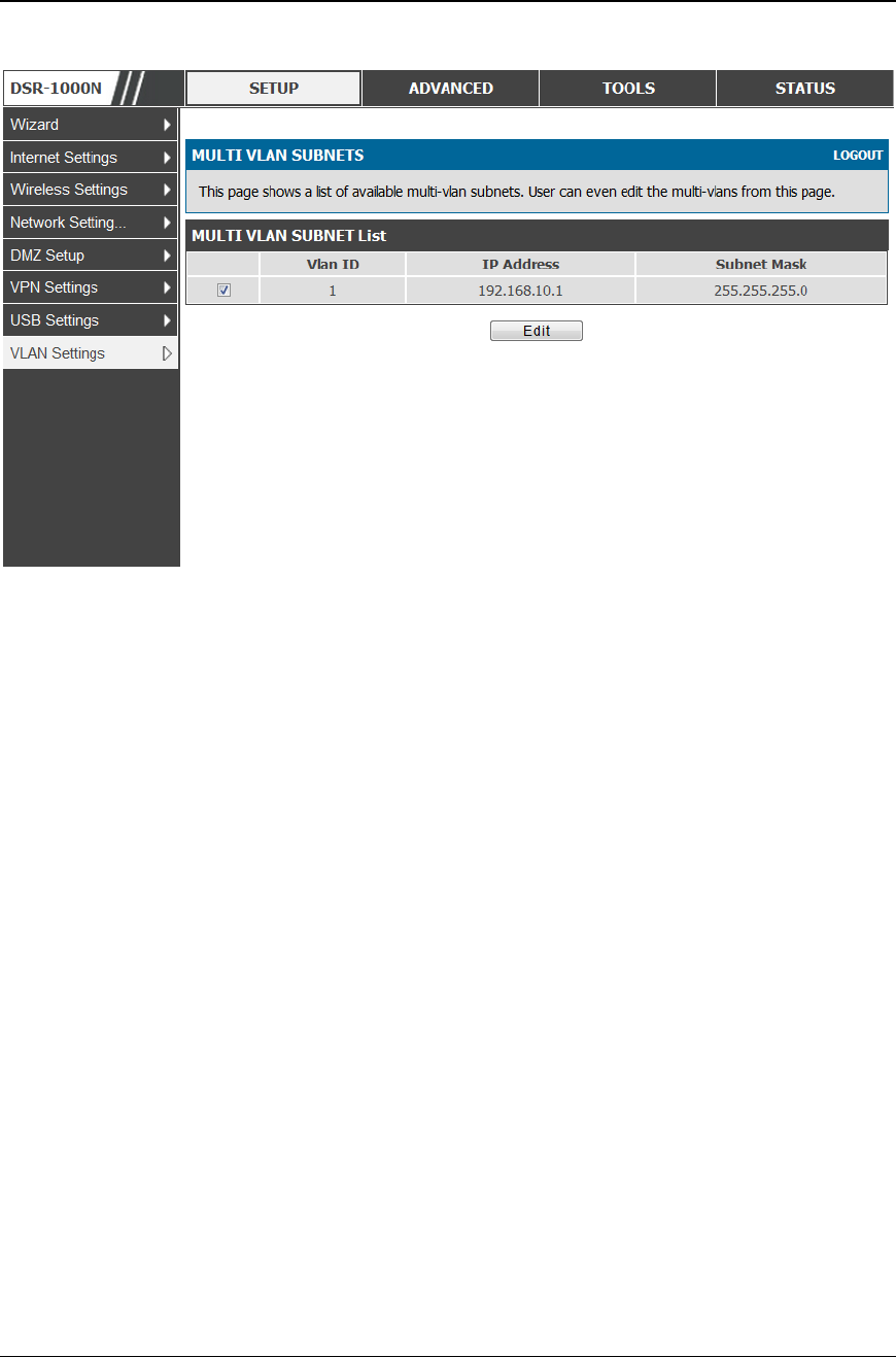
2.2.2 Multiple VLAN Subnets
Setup > VLAN Settings > Multi VLAN Settings
This page shows a list of available multi -VLAN subnets. Each configured VLAN ID
can map directly to a subnet within the LAN. Each LAN port can be assigned a
unique IP address and a VLAN specific DHCP server can be configured to assign IP
address leases to devices on this VLAN.
VLAN ID: The PVID of the VLAN that will have all member devices be part of the
same subnet range.
IP Address: The IP address associated with a port assigned this VLAN ID.
Subnet Mask: Subnet Mask for the above IP Address
Unified Services Router User Manual
27
Figure 10: Multi ple VLAN Subnets
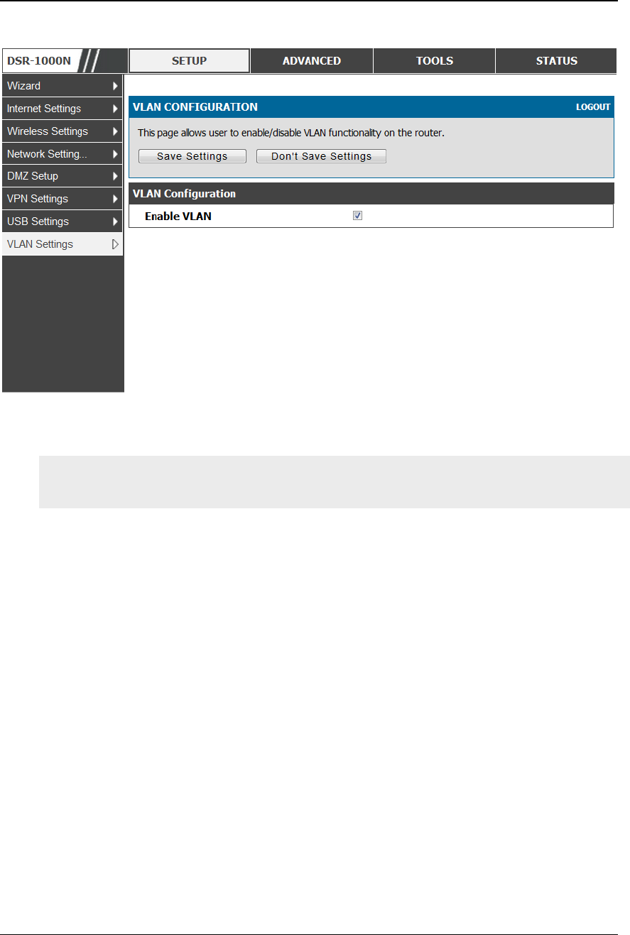
2.2.3 VLAN configuration
Setup > VLAN Settings > VLANconfiguration
This page allows enabling or disabling the VLAN function on the router. Virtual
LANs can be created in this router to provide segmentation capabilities for firewall
rules and VPN policies. The LAN network is considered the default VLAN. Check
the Enable VLAN box to add VLAN functionality to the LAN.
Unified Services Router User Manual
28
Figure 11: VLA N Configuration
2.3 Configurable Port: DMZ Setup
DSR-150/150N/250/250N does not have a configurable port – there is no DMZ
support.
This router supports one of the physical ports to be configured as a secondary WAN
Ethernet port or a dedicated DMZ port. A DMZ is a sub network that is open to the
public but behind the firewall. The DMZ adds an additional layer of security to the
LAN, as specific services/ports that are exposed to the internet on the DMZ do not
have to be exposed on the LAN. It is recommended that hosts that must be exposed to
the internet (such as web or email servers) be placed in the DMZ network. Firewall
rules can be allowed to permit access specific services/ports to the DMZ from both
the LAN or WAN. In the event of an attack to any of the DMZ nodes, the LAN is not
necessarily vulnerable as well.
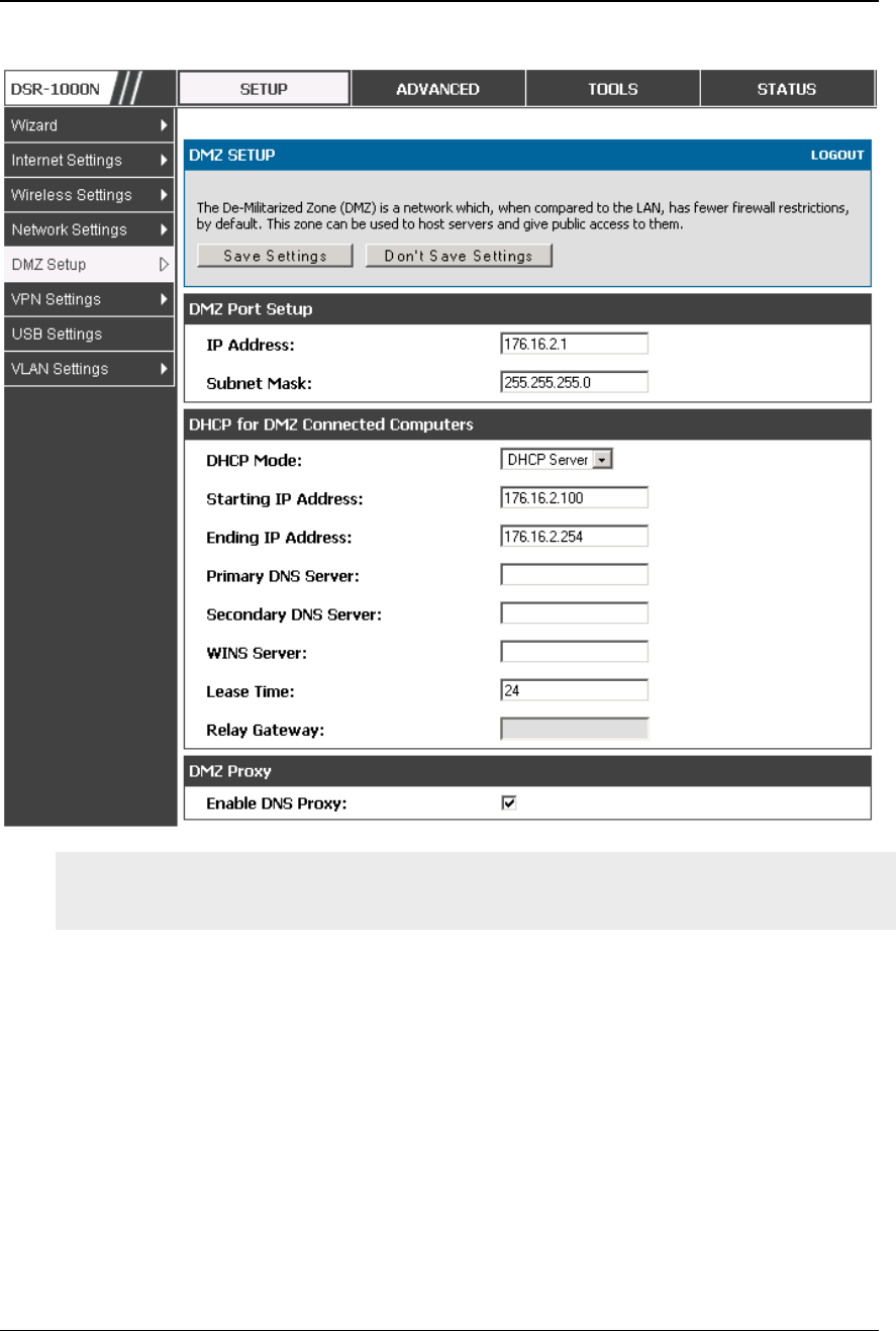
Setup > DMZ Setup > DMZ Setup Configuration
DMZ configuration is identical to the LAN configuration. There are no restrictions on
the IP address or subnet assigned to the DMZ port, other than the fact that it cannot
be identical to the IP address given to the LAN interface of this gateway.
Unified Services Router User Manual
29
Figure 12: DM Z configuration
In order to configure a DMZ port, the router’s configurable port must be set to
DMZ in the Setup > Internet Settings > Configurable Port page.
2.4 Universal Plug and Play (UPnP)
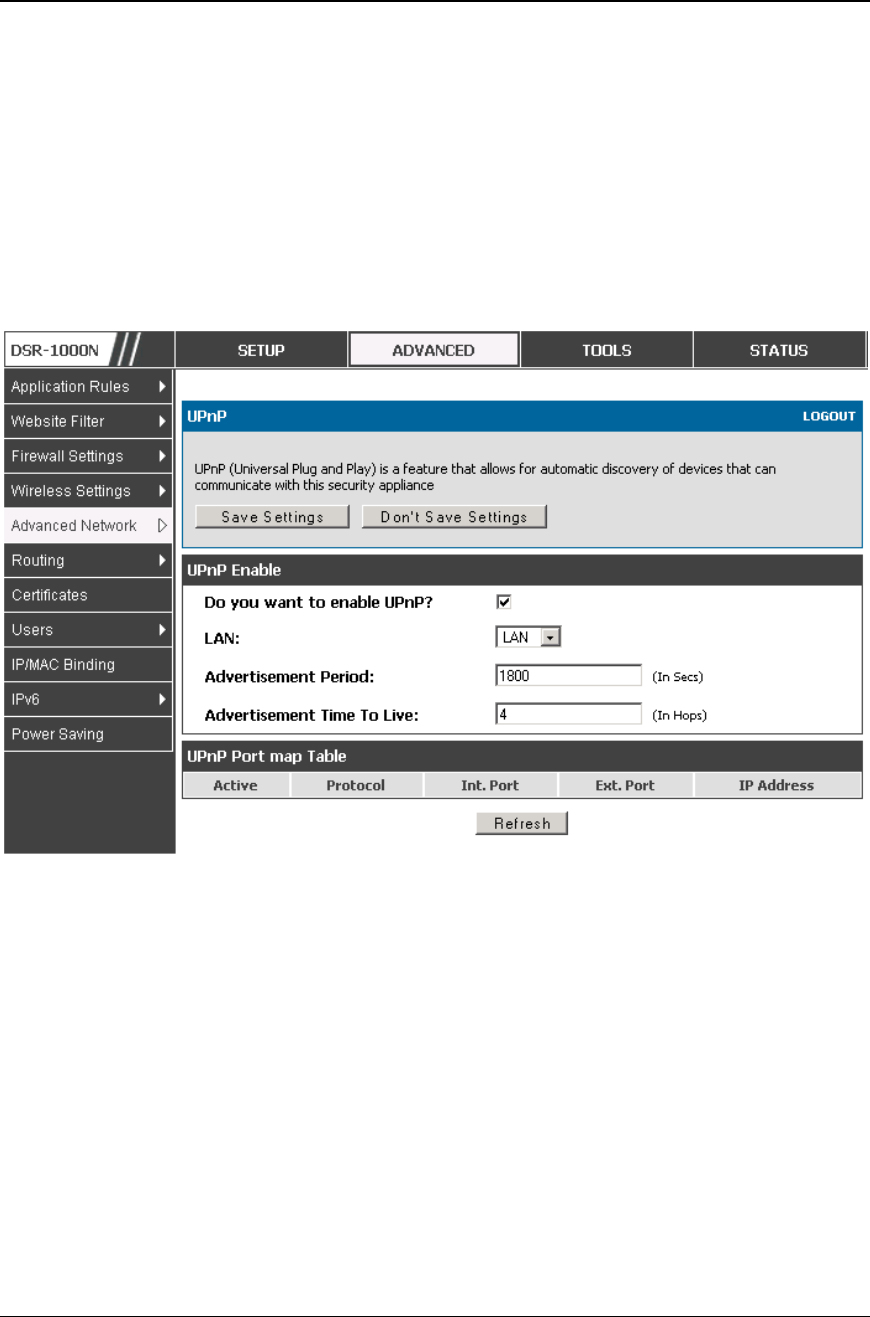
Advanced > Advanced Network > UPnP
Universal Plug and Play (UPnP) is a feature that allows the router to discovery
devices on the network that can communicate with the router and allow for auto
configuration. If a network device is detected by UPnP, the router can open internal
or external ports for the traffic protocol required by that network device.
Once UPnP is enabled, you can configure the router to detect UPnP -supporting
devices on the LAN (or a configured VLAN). If disabled, the router will not allow for
automatic device configuration.
Configure the following settings to use UPnP:
Unified Services Router User Manual
30
Advertisement Period: This is the frequency that the router broadcasts UPnP
information over the network. A large value will minimize network traffic but
cause delays in identifying new UPnP devices to the network.
Advertisement Time to Live: This is expressed in hops for each UPnP packet. This
is the number of steps a packet is allowed to propagate before being discarded.
Small values will limit the UPnP broadcast range. A default of 4 is typical for
networks with few switches.
Figure 13: UP nP Configuration
UPnP Port map Table
The UPnP Port map Table has the details of UPnP devices that respond to the router’s
advertisements. The following information is displayed for each detected device:
Active: A yes/no indicating whether the port of the UPnP device that established a
connection is currently active
Protocol: The network protocol (i.e. HTTP, FTP, etc.) used by the DSR
Int. Port (Internal Port): The internal ports opened by UPnP (if any)
Ext. Port (External Port): The external ports opened by UPnP (if any)
IP Address: The IP address of the UPnP device detected by this router
Click Refresh to refresh the portmap table and search for any new UPnP devices.

Unified Services Router User Manual
31
2.5 Captive Portal
DSR-150/150N/250/250N does not have support for the Captive Portal feature.
LAN users can gain internet access via web portal authentication with the DSR.
Also referred to as Run-Time Authentication, a Captive Portal is ideal for a web
café scenario where users initiate HTTP connection requests for web access but are
not interested in accessing any LAN services. Firewall policies underneath will
define which users require authentication for HTTP access, and when a matching
user request is made the DSR will intercept the request and prompt for a username /
password. The login credentials are compared against the RunTimeAuth users in
user database prior to granting HTTP access.
Captive Portal is available for LAN users only and not for DMZ hosts.
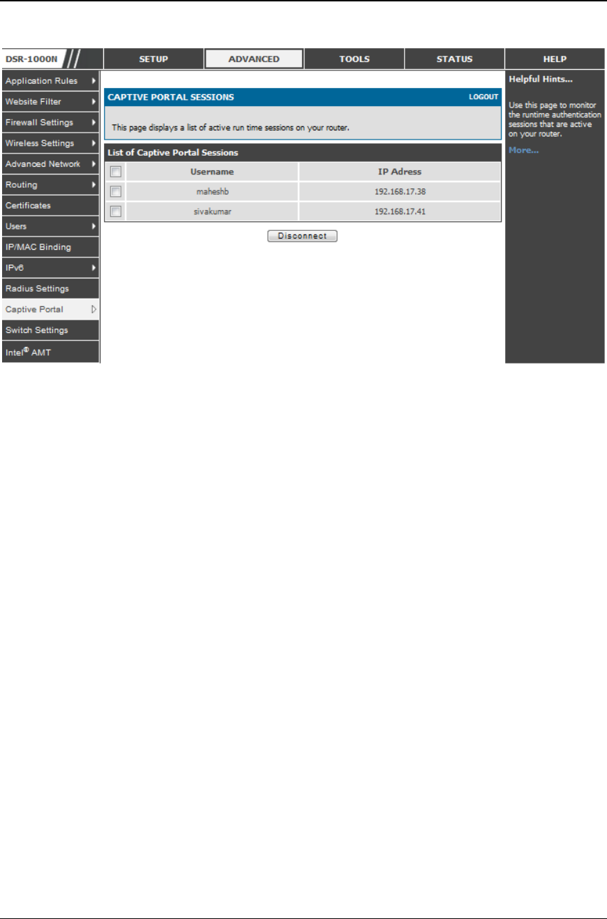
Advanced > Captive Portal >Captive Portal Sessions
The Active Runtime internet sessions through the router’s firewall are listed in the
below table. These users are present in the local or external user database and have
had their login credentials approved for internet access. A ‘Disconnect’ button
allows the DSR admin to selectively drop an authenticated user.
Unified Services Router User Manual
32
Figure 14: Active Runtime sessio ns
2.6 Captive portal setup
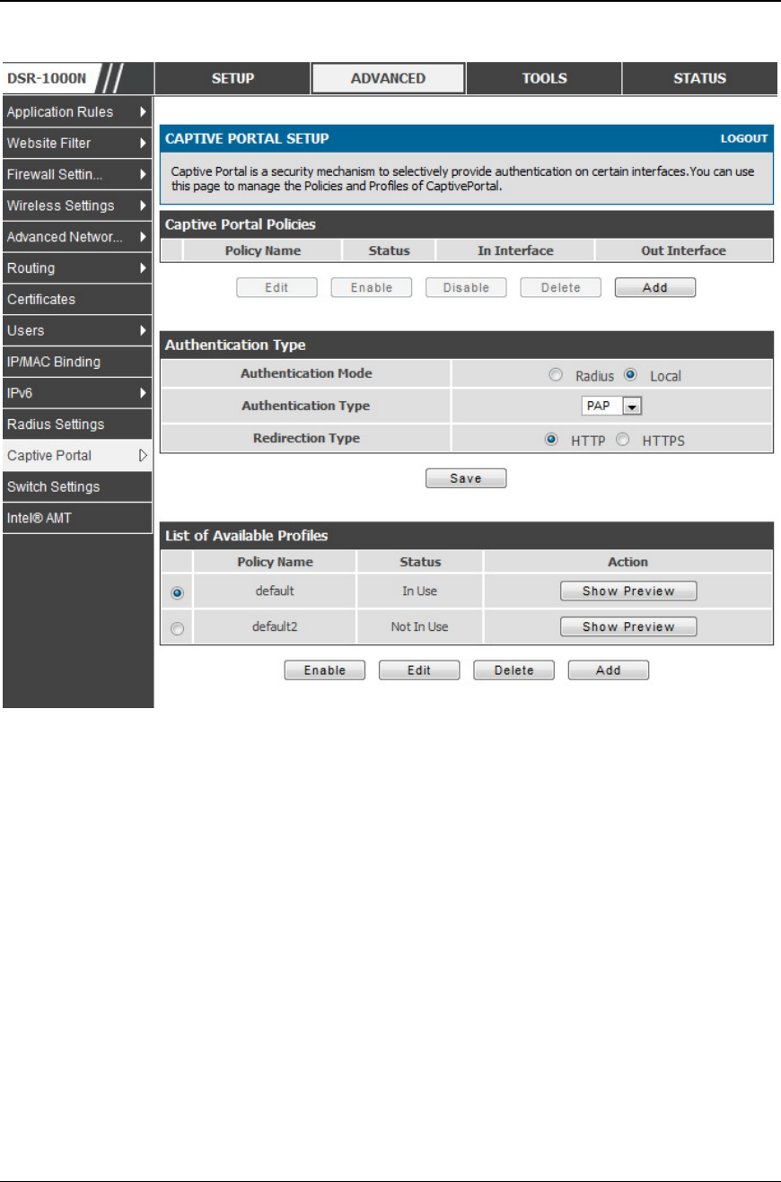
Advanced > Captive Portal >Captive Portal Setup
Captive Portal is a security mechanism to selectively provide authentication on
certain interfaces. This page allows to manage the Policies and Profiles of
CaptivePortal.
Unified Services Router User Manual
33
Figure 15: Cap tive Portal Setup
Captive Portal Policies: The List of Available CaptivePortal Policies are shown in
this table.
Authentication Type: This allows in choosing the authentication mode, type and
redirection type.
List of Available Profiles: Any one of these profiles can be used for Captive Portal
Login page while enabling Captive Portal.
Unified Services Router User Manual
34
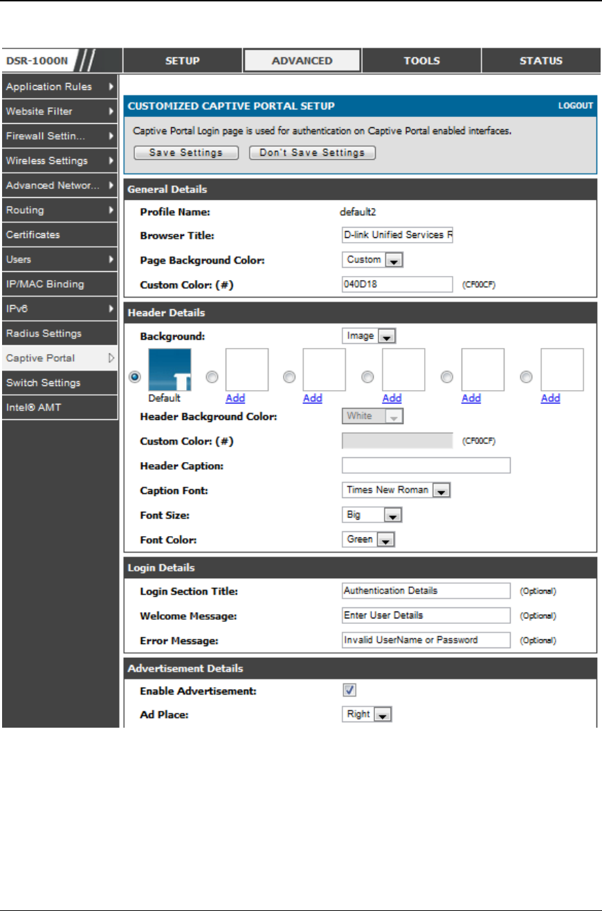
Figure 16: Customi zed Captive Portal Setup
Click “Add” in the Captive Portal setup page to allow defining customized captive
portal login page information (Page Background Color, Header Details, Header
Caption, Login Section Details, Adverti sement Details, Footer Details and Captive
Portal Header Image).
Unified Services Router User Manual
35
Chapter 3. Connecting to the Internet:
WAN Setup
This router has two WAN ports that can be used to establish a connection to the
internet. The following ISP connection types are supported: DHCP, Static , PPPoE,
PPTP, L2TP, 3G Internet (via USB modem).
It is assumed that you have arranged for internet service with your Internet Service
Provider (ISP). Please contact your ISP or network administrator for the configuration
information that will be required to setup the router.
3.1 Internet Setup Wizard
Setup > Wizard > Internet
The Internet Connection Setup Wizard is available for users new to networking. By
going through a few straightforward configuration pages you can take the information
provided by your ISP to get your WAN connection up and enable internet access for
your network.
Figure 17: Inter net Connection Set up Wizard
You can start using the Wizard by logging in with the administrator password for the
router. Once authenticated set the time zone that you are located in, and then choose
the type of ISP connection type: DHCP, Static, PPPoE, PPTP, L2TP. Depending on
the connection type a username/password may be required to register this router with
the ISP. In most cases the default settings can be used if the ISP did not specify that
parameter. The last step in the Wizard is to click the Connect button, which confirms
the settings by establishing a link with the ISP. Once connected, you can move on and
configure other features in this router.

Unified Services Router User Manual
36
3G Internet access with a USB modem is supported on WAN 3. The Internet
Connection Setup Wizard assists with the primary WAN port (WAN1)
configuration only.
3.2 WAN Configuration
Setup > Internet Settings > WAN1 Setup
You must either allow the router to detect WAN connection type automatically or
configure manually the following basic settings to enable Internet connectivity:
ISP Connection type: Based on the ISP you have selected for the primary WAN
link for this router, choose Static IP address, DHCP client, Point-to-Point
Tunneling Protocol (PPTP), Point -to-Point Protocol over Ethernet (PPPoE), Layer
2 Tunneling Protocol (L2TP). Required fields for the selected ISP type become
highlighted. Enter the following information as needed and as provided by your
ISP:
PPPoE Profile Name. This menu lists configured PPPoE profiles, particularly
useful when configuring multiple PPPoE connections (i.e. for Japan ISPs that
have multiple PPPoE support).
ISP login information. This is required for PPTP and L2TP ISPs.
User Name
Password
Secret (required for L2TP only)
MPPE Encryption: For PPTP links, your ISP may require you to enable Microsoft
Point-to-Point Encryption (MPPE).
Split Tunnel (supported for PPTP and L2TP connection). This setting allows your
LAN hosts to access internet sites over this WAN link while still permitting VPN
traffic to be directed to a VPN configured on this WAN port.
If split tunnel is enabled, DSR won’t expect a default route from the ISP server. In
such case, user has to take care of routing manually by configuring the routing from
Static Routing page.
Connectivity Type: To keep the connection always on, click Keep Connected. To
log out after the connection is idle for a period of time (useful if your ISP costs are
based on logon times), click Idle Timeout and enter the time, in minutes, to wait
before disconnecting in the Idle Time field.

Unified Services Router User Manual
37
My IP Address: Enter the IP address assigned to you by the ISP.
Server IP Address: Enter the IP address of the PPTP or L2TP server.
DSR-150/150N/250/250N doesn’t have a dual WAN support.
3.2.1 WAN Port IP address
Your ISP assigns you an IP address that is either dynamic (newly generated each
time you log in) or static (permanent). The IP Address Source option allows you to
define whether the address is statically provided by the ISP or should be received
dynamically at each login. If static, enter your IP address, IPv4 subnet mask, and the
ISP gateway’s IP address. PPTP and L2TP ISPs also can provide a static IP address
and subnet to configure, however the default is to receive that information
dynamically from the ISP.
3.2.2 WAN DNS Servers
The IP Addresses of WAN Domain Name Servers (DNS) are typically provided
dynamically from the ISP but in some cases you can define the static IP addresses of
the DNS servers. DNS servers map Internet domain names (example:
www.google.com) to IP addresses. Click to indicate whether to get DNS server
addresses automatically from your ISP or to use ISP -specified addresses. If its
latter, enter addresses for the primary a nd secondary DNS servers. To avoid
connectivity problems, ensure that you enter the addresses correctly.
3.2.3 DHCP WAN
For DHCP client connections, you can choose the MAC address of the router to
register with the ISP. In some cases you may need to clone the LAN host’s MAC
address if the ISP is registered with that LAN host.
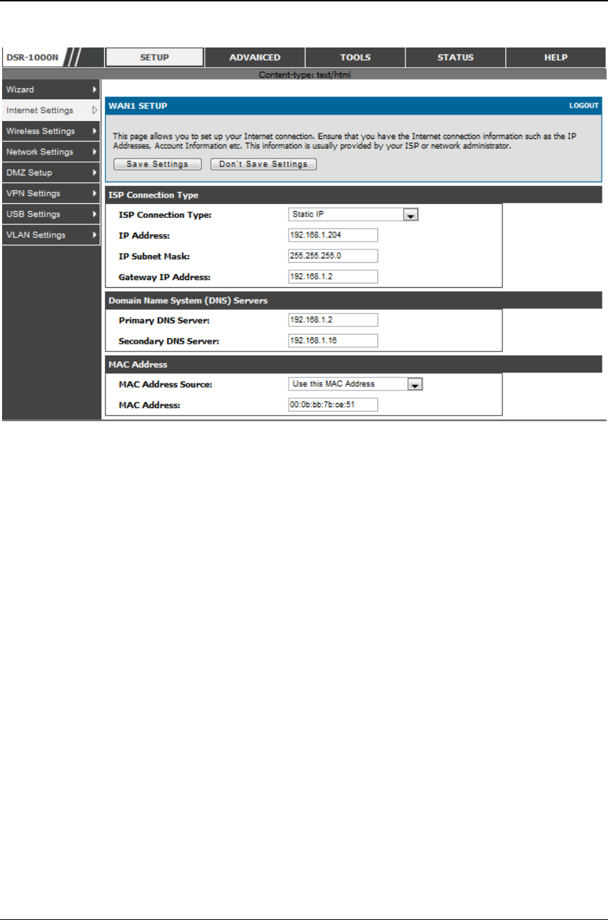
Unified Services Router User Manual
38
Figure 18: Manual WAN configuration
3.2.4 PPPoE
Setup > Internet Settings
The PPPoE ISP settings are defined on the WAN Configuration page. There are two
types of PPPoE ISP’s supported by the DSR: the standard username/password
PPPoE and Japan Multiple PPPoE.
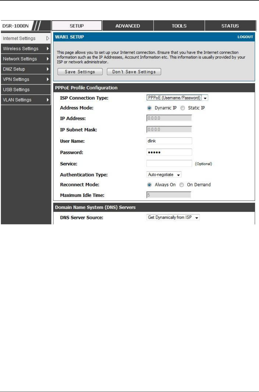
Unified Services Router User Manual
39
Figure 19: PPPoE co nfiguration f or sta ndard ISPs
Most PPPoE ISP’s use a single control and data connection, and require username /
password credentials to login and authenticate the DSR with the ISP. The ISP
connection type for this case is “PPPoE (Username/Password)”. The GUI will
prompt you for authentication, service, and connection settings in order to establish
the PPPoE link.
For some ISP’s, most popular in Japan, the use of “Japanese Multiple PPPoE” is
required in order to establish concurrent primary and secondary PPPoE connections
between the DSR and the ISP. The Primary connection is used for the bulk of data
and internet traffic and the Secondary PPPoE connection carries ISP specific (i.e.
control) traffic between the DSR and the ISP.
Unified Services Router User Manual
40
Figure 20: WAN conf iguration for Japanese Multiple PPPoE (part 1)
There are a few key elements of a multiple PPPoE connection:
Primary and secondary connections are concurrent
Each session has a DNS server source for domain name lookup, this can be assigned by
the ISP or configured through the GUI
The DSR acts as a DNS proxy for LAN users
Only HTTP requests that specifically identify the secondary connection’s domain name
(for example *.flets) will use the secondary profile to access the content available
through this secondary PPPoE terminal. All other HTTP / HTTPS requests go through
the primary PPPoE connection.
Unified Services Router User Manual
41
When Japanese multiple PPPoE is configured and secondary connection is up, some predefined
routes are added on that interface. These routes are needed to access the internal domain of the
ISP where he hosts various services. These routes can even be configured through the static
routing page as well.
Figure 21: WAN conf iguration for Multiple PPPoE ( part 2)
3.2.5 Russia L2TP and PPTP WAN
For Russia L2TP WAN connections, you can choose the address mode of the
connection to get an IP address from the ISP or configure a static IP address
provided by the ISP. For DHCP client connections, you can choose the MAC
address of the router to register with the ISP. In some cases you may need to clone
the LAN host’s MAC address if the ISP is registered with that LAN host.
Unified Services Router User Manual
42
Figure 22: Russia L2TP ISP configuration
3.2.6 Russia Dual Access PPPoE
For Russia dual access PPPoE connections, you can choose the address mode of the
connection to get an IP address from the ISP or configure a static IP address
provided by the ISP.
Unified Services Router User Manual
43
Figure 23: Russia Dual access PPPoE configuration
3.2.7 WAN Configuration in an IPv6 Network
Advanced > IPv6 > IPv6 WAN1 Config
For IPv6 WAN connections, this router can have a static IPv6 address or receive
connection information when configured as a DHCPv6 client. In the case where the
ISP assigns you a fixed address to access the internet, the static configuration
settings must be completed. In addition to the IPv6 address assigned to your router,
the IPv6 prefix length defined by the ISP is needed. The default IPv6 Gateway
address is the server at the ISP that this router will connect to for accessing the
internet. The primary and secondary DNS servers on the ISP’s IPv6 network are
used for resolving internet addresses, and these are provided along with the static IP
address and prefix length from the ISP.
When the ISP allows you to obtain the WAN IP settings via DHCP, you need to
provide details for the DHCPv6 client configuration. The DHCPv6 client on the
gateway can be either stateless or stateful. If a stateful client is selected the gateway
will connect to the ISP’s DHCPv6 server for a leased address. For stateless DHCP
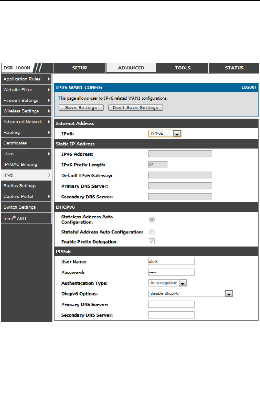
Unified Services Router User Manual
44
there need not be a DHCPv6 server available at the ISP, rather ICMPv6 discover
messages will originate from this gateway and will be used for auto configuration. A
third option to specify the IP address and prefix length of a preferred DHCPv6
server is available as well.
Figure 24: IPv6 W AN Setup page
Prefix Delegation: Select this option to request router advertisement prefix from any
available DHCPv6 servers available on the ISP, the obtained prefix is updated to the
advertised prefixes on the LAN side. This option can be selected only in Statesless
Address Auto Configuration mode of DHCPv6 Client.
When IPv6 is PPPoE type, the following PPPoE fields are enabled.
Username: Enter the username required to log in to the ISP.

Unified Services Router User Manual
45
Password: Enter the password required to login to the ISP.
Authentication Type: The type of Authentication in use by the profile: Auto -
Negotiate/PAP/CHAP/MS-CHAP/MS-CHAPv2.
Dhcpv6 Options: The mode of Dhcpv6 client that will start in this mode:
disable dhcpv6/stateless dhcpv6/stateful dhcpv6/ stateless dhcpv6 with prefix
delegation.
Primary DNS Server: Enter a valid primary DNS Server IP Address.
Secondary DNS Server: Enter a valid secondary DNS Server IP Address.
Click Save Settings to save your changes.
3.2.8 Checking WAN Status
Setup > Internet Settings > WAN1 Status
The status and summary of configured settings for both WAN1, WAN2 and WAN3
are available on the WAN Status page. You can view the following key connection
status information for each WAN port:
Connection time: The connection uptime
Connection type: Dynamic IP or Static IP
Connection state: This is whether the WAN is connected or disconnected to
an ISP. The Link State is whether the physical WAN connection in place;
the Link State can be UP (i.e. cable inserted) while the WAN Connection
State is down.
IP address / subnet mask: IP Address assigned
Gateway IP address: WAN Gateway Address
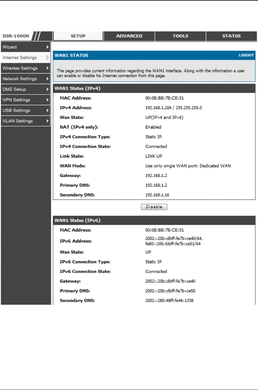
Unified Services Router User Manual
46
Figure 25: Connecti on Status information for both WAN ports
The WAN status page allows you to Enable or Disable static WAN l inks. For WAN
settings that are dynamically received from the ISP, you can Renew or Release the
link parameters if required.
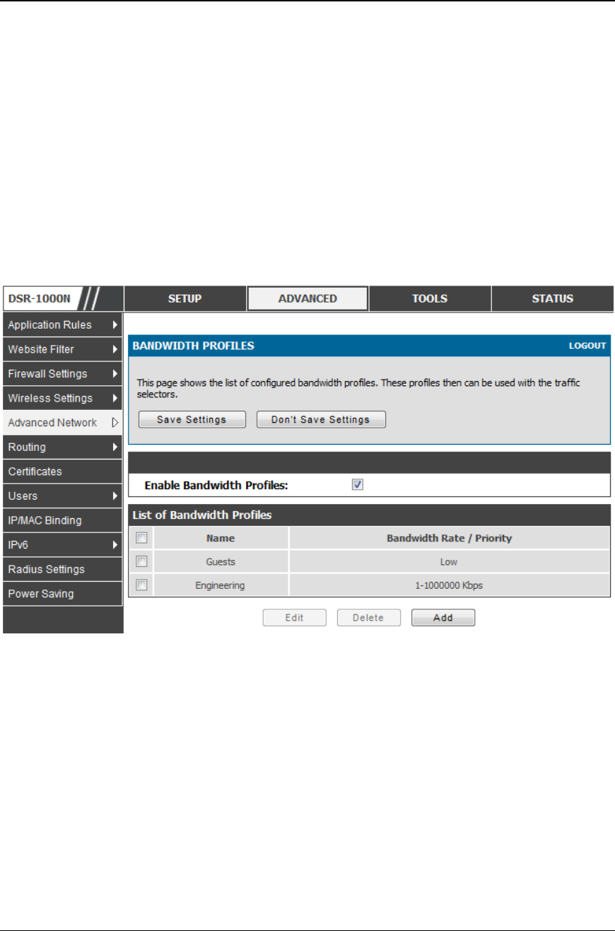
Unified Services Router User Manual
47
3.3 Bandwidth Controls
Advanced > Advanced Network > Traffic Management > Bandwidth Profiles
Bandwidth profiles allow you to regulate t he traffic flow from the LAN to WAN 1 or
WAN 2. This is useful to ensure that low priority LAN users (l ike guests or HTTP
service) do not monopolize the available WAN’s bandwidth for cost -savings or
bandwidth-priority-allocation purposes.
Bandwidth profiles configuration consists of enabling the bandwidth control feature
from the GUI and adding a profile which defines the control parameters. The profile
can then be associated with a traffic selector, so that bandwidth profile can be applied
to the traffic matching the selectors. Selectors are elements like IP addresses or
services that would trigger the configured bandwidth regulation.
Figure 26: Li st of Configured Bandwi dth Profiles
To create a new bandwidth profile, click Add in the List of Bandwidth Profiles. The
following configuration parameters are used to define a bandwidth profile:
Profile Name: This identifier is used to associate the configured profile to the
traffic selector
You can choose to limit the bandwidth either using priority or rate.
If using priority “Low”, “High”, and “Medium” can be selected. If there
is a low priority profile associated with traffic selector A and a high
priority profile associated with traffic selector B, then the WAN
bandwidth allocation preference will be to traffic selector B packets.
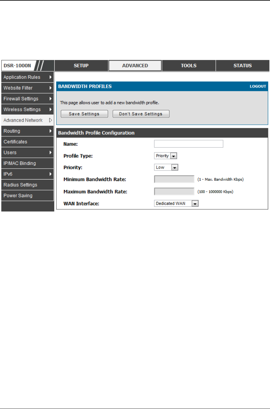
Unified Services Router User Manual
48
For finer control, the Rate profile type can be used. With this option the
minimum and maximum bandwidth allowed by this profile can be limited.
Choose the WAN interface that the profile should be associated with.
Figure 27: Ba ndwidth Profile Co nfiguration page
Advanced > Advanced Network > Traffic Management > Traffic Selectors
Once a profile has been created it can then be associated with a traffic flow from the
LAN to WAN. To create a traffic selector, click Add on the Traffic Selectors page.
Traffic selector configuration binds a bandwidth profile to a type or source of LAN
traffic with the following settings:
Available profiles: Assign one of the defined bandwidth profiles
Service: You can have the selected bandwidth regulation apply to a specific
service (i.e. FTP) from the LAN. If you do not see a service that you want, you
can configure a custom service through the Advanced > Firewall Settings >
Custom Services page. To have the profile apply to all services, select ANY.
Traffic Selector Match Type: this defines the parameter to filter against when
applying the bandwidth profile. A specific machine on the LAN can be
identified via IP address or MAC address, or the profile can apply to a LAN
port or VLAN group. As well a wireless network can be selected by its BSSID
for bandwidth shaping.
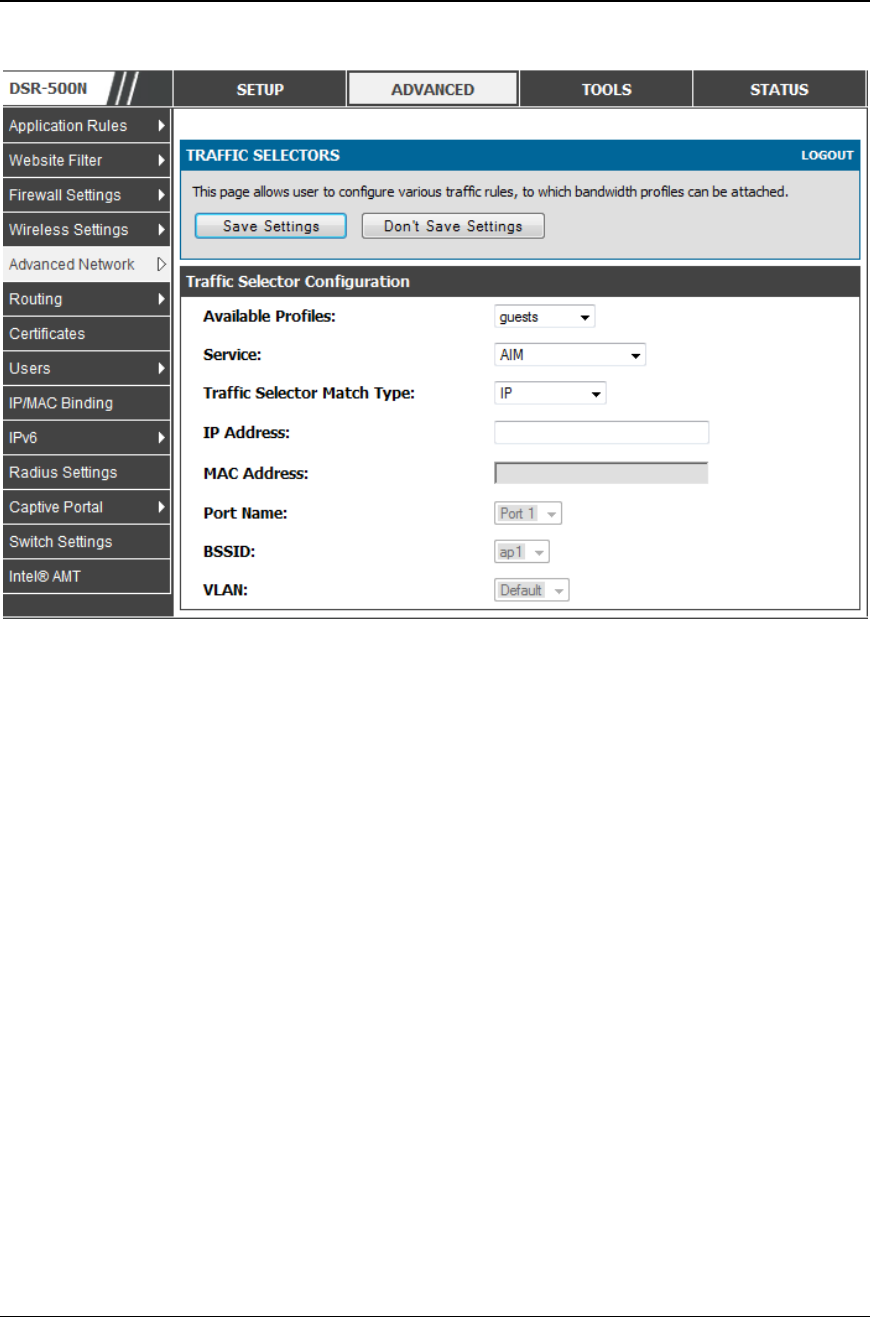
Unified Services Router User Manual
49
Figure 28: Traf fic Selector Configuration
3.4 Features with Multiple WAN Links
This router supports multiple WAN links. This allows you to take advantage of
failover and load balancing features to ensure certain internet dependent services are
prioritized in the event of unstable WAN connectivity on one of the ports.
Setup > Internet Settings > WAN Mode
To use Auto Failover or Load Balancing, WAN link failure detection must be
configured. This involves accessing DNS servers on the internet or ping to an internet
address (user defined). If required, you can configure the number of retry atte mpts
when the link seems to be disconnected or the threshold of failures that determines if
a WAN port is down.
3.4.1 Auto Failover
In this case one of your WAN ports is assigned as the primary internet link for all
internet traffic. The secondary WAN port is used for redundancy in case the primary
link goes down for any reason. Both WAN ports (primary and secondary) must be
configured to connect to the respective ISP’s before enabling this feature. The
secondary WAN port will remain unconnected until a failure i s detected on the
primary link (either port can be assigned as the primary). In the event of a failure on
the primary port, all internet traffic will be rolled over to the backup port. When
configured in Auto Failover mode, the link status of the primary W AN port is
checked at regular intervals as defined by the failure detection settings.

Unified Services Router User Manual
50
Note that both WAN1, WAN2 and WAN3 can be configured as the primary internet
link.
Auto-Rollover using WAN port
Primary WAN: Selected WAN is the primary link ( WAN1/WAN2/WAN3)
Secondary WAN: Selected WAN is the secondary link.
Failover Detection Settings: To check connectivity of the primary internet link, one
of the following failure detection methods can be selected:
DNS lookup using WAN DNS Servers: DNS Lookup of the DN S Servers of
the primary link are used to detect primary WAN connectivity.
DNS lookup using DNS Servers: DNS Lookup of the custom DNS Servers
can be specified to check the connectivity of the primary link.
Ping these IP addresses: These IP's will be pinged at regular intervals to
check the connectivity of the primary link.
Retry Interval is: The number tells the router how often it should run the
above configured failure detection method.
Failover after: This sets the number of retries after which failover is
initiated.
3.4.2 Load Balancing
This feature allows you to use multiple WAN links (and presumably multiple ISP’s)
simultaneously. After configuring more than one WAN port, the load balancing
option is available to carry traffic over more than one link. Protocol bindings are
used to segregate and assign services over one WAN port in order to manage
internet flow. The configured failure detection method is used at regular intervals on
all configured WAN ports when in Load Balancing mode.
DSR currently support three algorithms for Load Balancing:
Round Robin: This algorithm is particularly useful when the connection speed of
one WAN port greatly differs from another. In this case you can define protocol
bindings to route low-latency services (such as VOIP) over the higher-speed link
and let low-volume background traffic (such as SMTP) go over the lower speed link.
Protocol binding is explained in next section.
Spill Over: If Spill Over method is selected, WAN1 acts as a dedicated link till a
threshold is reached. After this, WAN2 will be used for new connections. You can
configure spill-over mode by using following options:
Load Tolerance: It is the percentage of bandwidth after which the router
switches to secondary WAN.
Max Bandwidth: This sets the maximum bandwidth tolerable by the primary
WAN.
If the link bandwidth goes above the load tolerance value of max bandwidth, the
router will spill-over the next connections to secondary WAN.
For example, if the maximum bandwidth of primary WAN is 1 Kbps and the load
tolerance is set to 70. Now every time a new connection is established the
bandwidth increases. After a certain number of connections say bandwidth reached

Unified Services Router User Manual
51
70% of 1Kbps, the new connections will be spilled -over to secondary WAN. The
maximum value of load tolerance is 80 and the least is 20.
Protocol Bindings: Refer Section 3.4.3 for details
Load balancing is particularly useful when the connection speed of one WAN port
greatly differs from another. In this case you can define protocol bindings to route
low-latency services (such as VOIP) over the higher-speed link and let low-volume
background traffic (such as SMTP) go over the lower speed link.
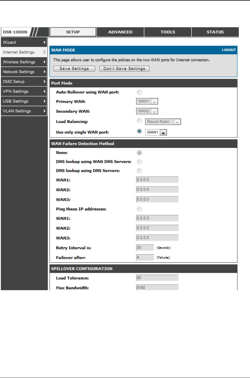
Unified Services Router User Manual
52
Figure 29: Load Bal ancing is available when multiple WAN ports are
configured and Pro tocol Bindings have been defined
3.4.3 Protocol Bindings
Advanced > Routing > Protocol Bindings
Protocol bindings are required when the Load Balancing feature is in use. Choosing
from a list of configured services or any of the user -defined services, the type of
traffic can be assigned to go over only one of the available WAN ports. For
increased flexibility the source network or machines can be specified as well as the
destination network or machines. For example the VOIP traffic for a set of LAN IP
addresses can be assigned to one WAN and any VOIP traffic from the remaining IP
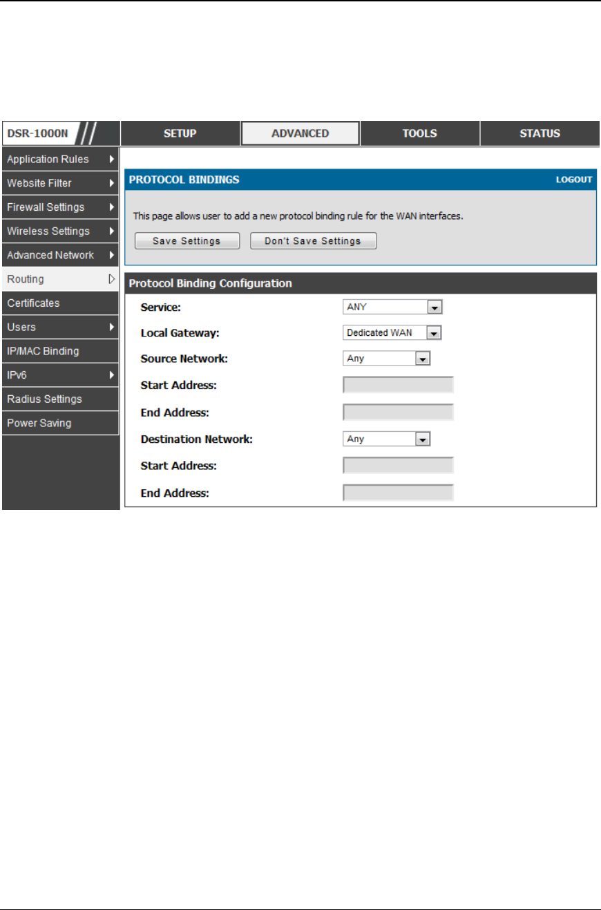
Unified Services Router User Manual
53
addresses can be assigned to the other WAN link. Protocol bindings are only
applicable when load balancing mode is enabled and more than one WAN is
configured.
Figure 30: Protocol binding setup to associate a service a nd/or LAN
so urce to a WAN and/or destination network
3.5 Routing Configuration
Routing between the LAN and WAN will impact the way this router handles traffic
that is received on any of its physical interf aces. The routing mode of the gateway is
core to the behaviour of the traffic flow between the secure LAN and the internet.
3.5.1 Routing Mode
Setup > Internet Settings > Routing Mode
This device supports classical routing, network address translation (NAT), an d
transport mode routing.
With classical routing, devices on the LAN can be directly accessed from the
internet by their public IP addresses (assuming appropriate firewall settings). If
your ISP has assigned an IP address for each of the computers that yo u use,
select Classic Routing.

Unified Services Router User Manual
54
NAT is a technique which allows several computers on a LAN to share an
Internet connection. The computers on the LAN use a "private" IP address
range while the WAN port on the router is configured with a single "public" IP
address. Along with connection sharing, NAT also hides internal IP addresses
from the computers on the Internet. NAT is required if your ISP has assigned
only one IP address to you. The computers that connect through the router will
need to be assigned IP addresses from a private subnet.
Transparent routing between the LAN and WAN does not perform NAT.
Broadcast and multicast packets that arrive on the LAN interface are switched
to the WAN and vice versa, if they do not get filtered by firewall or VPN
policies. To maintain the LAN and WAN in the same broadcast domain select
Transparent mode, which allows bridging of traffic from LAN to WAN and vice
versa, except for router-terminated traffic and other management traffic. All
DSR features (such as 3G modem support) are supported in transparent mode
assuming the LAN and WAN are configured to be in the same broadcast
domain.
NAT routing has a feature called “NAT Hair -pinning” that allows internal network
users on the LAN and DMZ to access internal servers (eg. an internal FTP server)
using their externally-known domain name. This is also referred to as “NAT
loopback” since LAN generated traffic is redirected through the firewall to reach
LAN servers by their external name.
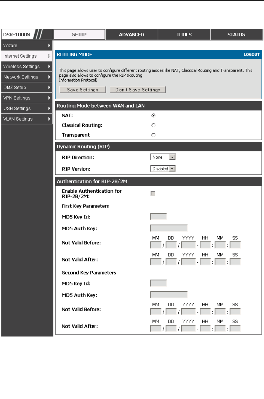
Unified Services Router User Manual
55
Figure 31: Routing Mode is used to conf igure traffic routi ng between
WAN and LAN, as well as Dynamic routi ng (RIP)

Unified Services Router User Manual
56
3.5.2 Dynamic Routing (RIP)
DSR- 150/150N/250/250N does not support RIP.
Setup > Internet Settings > Routing Mode
Dynamic routing using the Routing Information Protocol (RIP) is an Interior
Gateway Protocol (IGP) that is common in LANs. With RIP this router can exchange
routing information with other supported routers in the LAN and allow for dynamic
adjustment of routing tables in order to adapt to modifications in the LAN without
interrupting traffic flow.
The RIP direction will define how this router sends and receives RIP packets.
Choose between:
Both: The router both broadcasts its routing table and also processes RIP
information received from other routers. This is the recommended setting in
order to fully utilize RIP capabilities.
Out Only: The router broadcasts its routing table periodically but does not
accept RIP information from other routers.
In Only: The router accepts RIP information from other routers, but does not
broadcast its routing table.
None: The router neither broadcasts its route table nor does it accept any
RIP packets from other routers. This effectively disables RIP.
The RIP version is dependent on the RIP support of other routing
devices in the LAN.
Disabled: This is the setting when RIP is disabled.
RIP-1 is a class-based routing version that does not include subnet
information. This is the most commonly supported version.
RIP-2 includes all the functionality of RIPv1 plus it sup ports subnet
information. Though the data is sent in RIP -2 format for both RIP-2B and
RIP-2M, the mode in which packets are sent is different. RIP-2B broadcasts
data in the entire subnet while RIP-2M sends data to multicast addresses.
If RIP-2B or RIP-2M is the selected version, authentication between this router and
other routers (configured with the same RIP version) is required. MD5
authentication is used in a first/second key exchange process. The authentication
key validity lifetimes are configurable to ensure that the routing information
exchange is with current and supported routers detected on the LAN.

Unified Services Router User Manual
57
3.5.3 Static Routing
Advanced > Routing > Static Routing
Advanced > IPv6 > IPv6 Static Routing
Manually adding static routes to this device allows you to d efine the path selection
of traffic from one interface to another. There is no communication between this
router and other devices to account for changes in the path; once configured the
static route will be active and effective until the network changes.
The List of Static Routes displays all routes that have been added manually by an
administrator and allows several operations on the static routes. The List of IPv4
Static Routes and List of IPv6 Static Routes share the same fields (with one
exception):
Name: Name of the route, for identification and management .
Active: Determines whether the route is active or inactive. A route can be
added to the table and made inactive, if not needed. This allows routes to be
used as needed without deleting and re-adding the entry. An inactive route is
not broadcast if RIP is enabled.
Private: Determines whether the route can be shared with other routers when
RIP is enabled. If the route is made private, then the route will not be shared
in a RIP broadcast or multicast. This is only applicable for IPv4 static
routes.
Destination: the route will lead to this destination host or IP address.
IP Subnet Mask: This is valid for IPv4 networks only , and identifies the
subnet that is affected by this static route
Interface: The physical network interface (WAN1, WAN2, WAN3, DMZ or
LAN), through which this route is accessible.
Gateway: IP address of the gateway through which the destination host or
network can be reached.
Metric: Determines the priority of the route. If multiple routes to the same
destination exist, the route with the lowest metric is chosen.
Unified Services Router User Manual
58
Figure 32: Static route co nfiguration f ields
3.5.4 OSPFv2
Advanced > Routing > OSPF
OSPF is an interior gateway protocol that routes Internet Protocol (IP) packets solely
within a single routing domain. It gathers link state information from available routers
and constructs a topology map of the network.
OSPF version 2 is a routing protocol which described in RFC2328 - OSPF Version 2.
OSPF is IGP (Interior Gateway Protocols).OSPF is widely used in large networks
such as ISP backbone and enterprise networks.
Unified Services Router User Manual
59
Figure 33: OSPFv 2 c onfigured parameter s
Interface: The physical network interface on which OSPFv2 is Enabled/Disabled.
Status: This column displays the Enable/Disable state of OSPFv2 for a particular
interface.
Area: The area to which the interface belongs. Two routers having a common
segment; their interfaces have to belong to the same area on that segment. The
interfaces should belong to the same subnet and have similar mask.
Priority: Helps to determine the OSPFv2 designated router for a network. The router
with the highest priority will be more eligible to become Designated Router. Setting
the value to 0, makes the router ineligible to become Designated Router. The default
value is 1.Lower value means higher priority.
HelloInterval: The number of seconds for HelloInterval timer value. Setting this
value, Hello packet will be sent every timer value seconds on the specified in terface.
This value must be the same for all routers attached to a common network. The
default value is 10 seconds.
DeadInterval: The number of seconds that a device’s hello packets must not have been
seen before its neighbours declare the OSPF router down. This value must be the
same for all routers attached to a common network. The default value is 40 seconds.
OSPF requires these intervals to be exactly the same between two neighbours. If any
of these intervals are different, these routers will not become neighbours on a
particular segment
Cost: The cost of sending a packet on an OSPFv2 interface.
Authentication Type:. This column displays the type of authentication to be used for
OSPFv2.If Authentication type is none the interface does not authenticate ospf
packets. If Authentication Type is Simple then ospf packets are authenticated using
simple text key. If Authentication Type is MD5 then the interface authenticates ospf
packets with MD5 authentication.
Unified Services Router User Manual
60
Figure 34: OSPFv2 configurati on
3.5.5 OSPFv3
Advanced > IPv6 > OSPF
Open Shortest Path First version 3 (OSPFv3) supports IPv6 . To enable an OSPFv3
process on a router, you need to enable the OSPFv3 process globally, assign the
OSPFv3 process a router ID, and enable the OSPFv3 process on related interfaces
Unified Services Router User Manual
61
Figure 35: OSPFv3 configured parameter s
Interface: The physical network interface on which OSPFv3 is Enabled/Disabled.
Status: This column displays the Enable/Disable state of OSPFv3 for a particular
interface.
Priority: Helps to determine the OSPFv3 designated router for a network. The router
with the highest priority will be more eligible to become Designated Router. Setting
the value to 0, makes the router ineligible to become Designated Router. The default
value is 1.Lower Value means higher priority.
HelloInterval: The number of seconds for HelloInterval timer value. Setting this
value, Hello packet will be sent every timer value seconds on the specified interface.
This value must be the same for all routers attach ed to a common network. The
default value is 10 seconds.
DeadInterval: The number of seconds that a device’s hello packets must not have been
seen before its neighbours declare the OSPF router down.This value must be the same
for all routers attached to a common network. The default value is 40 seconds.
OSPF requires these intervals to be exactly the same between two neighbours. If any
of these intervals are different, these routers will not become neighbours on a
particular segment
Cost: The cost of sending a packet on an OSPFv3 interface.
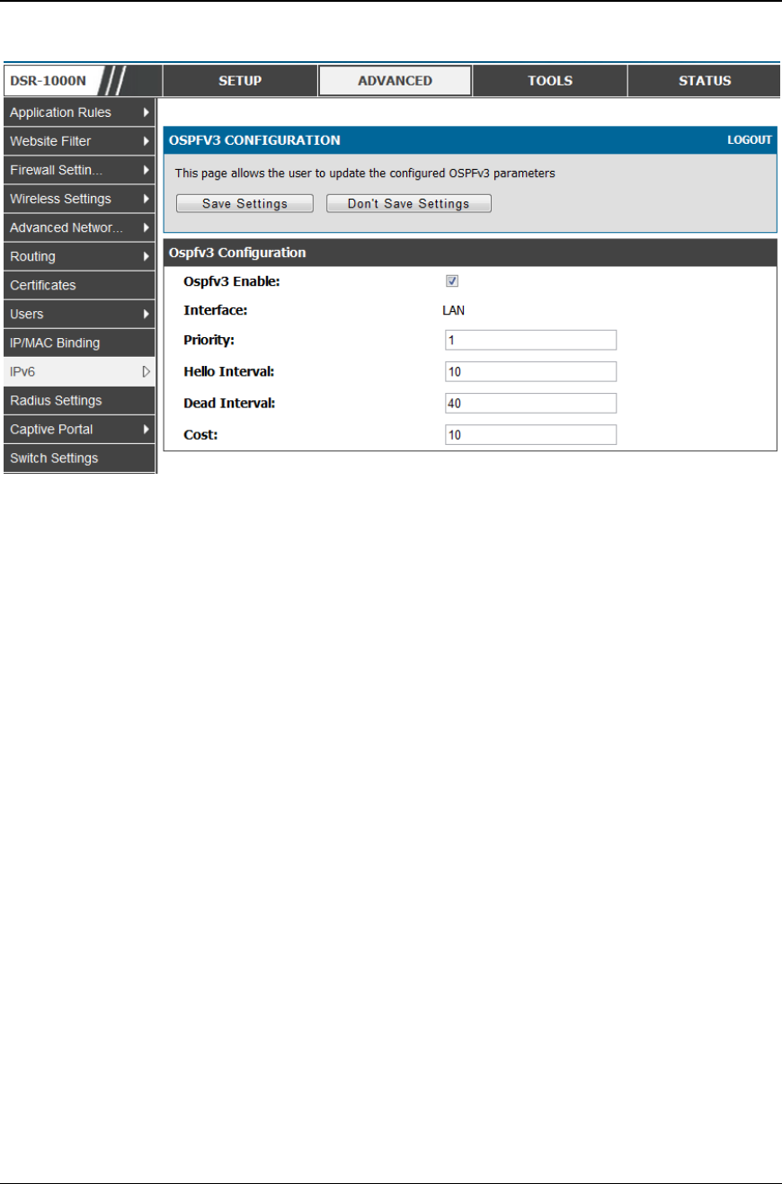
Unified Services Router User Manual
62
Figure 36: OSPFv3 configurati on
3.5.6 6to4 Tunneling
Advanced > IPv6 > 6to4 Tunneling
6to4 is an Internet transition mechanism for migrating from IPv4 to IPv6,
a system that allows IPv6 packets to be tran smitted over an IPv4
network. Select the check box to Enable Automatic Tunneling and
allow traffic from an IPv6 LAN to be sent over a IPv4 Option to reach a
remote IPv6 network.
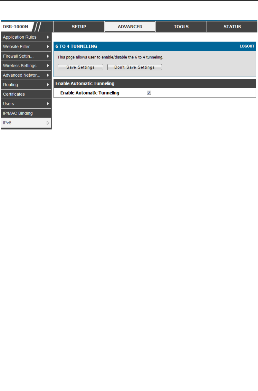
Unified Services Router User Manual
63
Figure 37: 6 to 4 tunneling
3.5.7 ISATAP Tunnels
Advanced > IPv6 > 6to4 Tunneling
ISATAP (Intra-Site Automatic Tunnel Addressing Protocol) is an IPv6
transition mechanism meant to transmit IPv6 packets between dual -stack
nodes on top of an IPv4 network. ISATAP specifies an IPv6-IPv4
compatibility address format as well as a means for site border router
discovery. ISATAP also specifies the operation of IPv6 over a specific
link layer - that being IPv4 used as a link layer for IPv6.
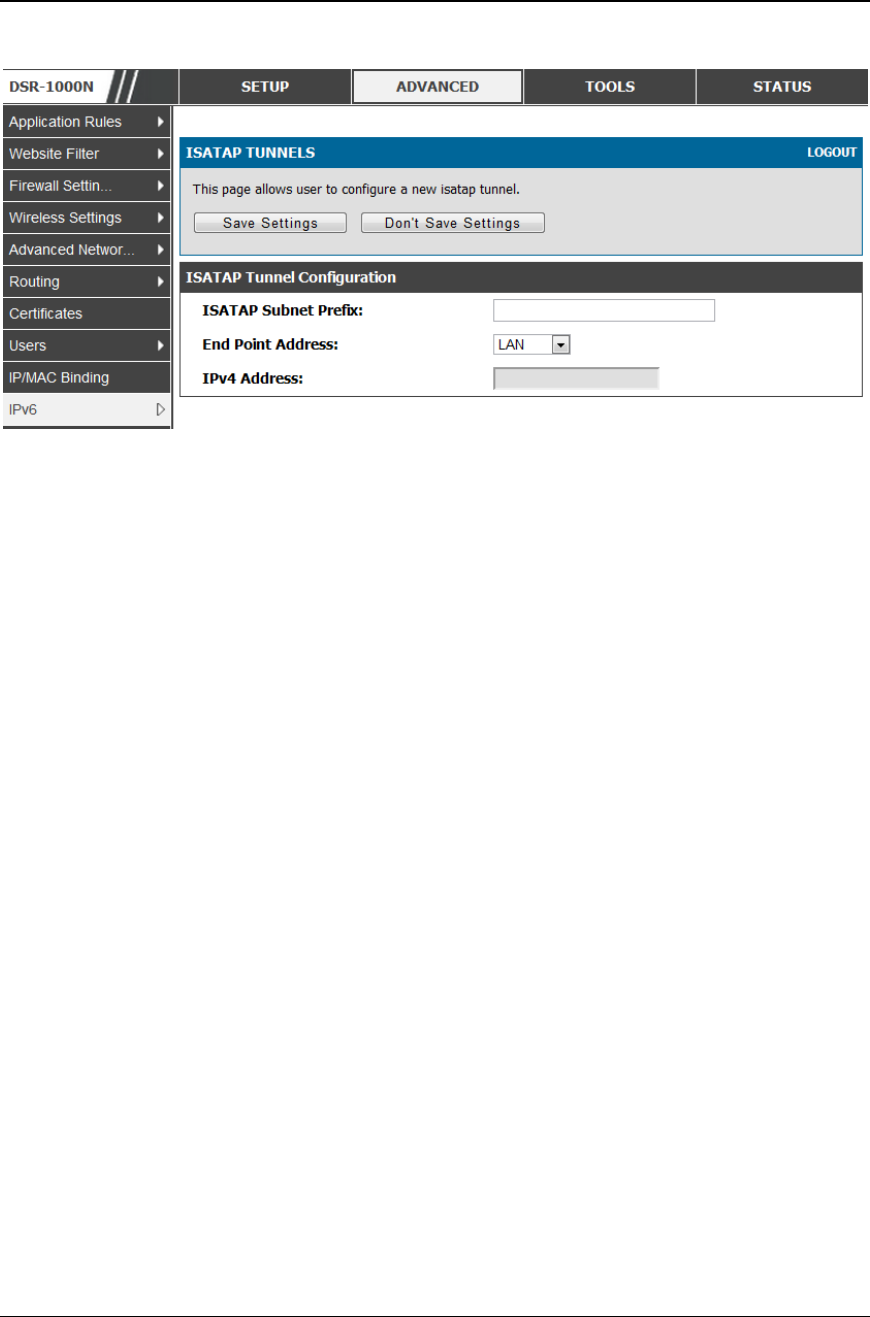
Unified Services Router User Manual
64
Figure 38: IS A T AP Tunnel s C o nf iguration
ISATAP Subnet Prefix: This is the 64-bit subnet prefix that is assigned
to the logical ISATAP subnet for this intranet. This can be obtained from
your ISP or internet registry, or derived from RFC 4193.
End Point Address: This is the endpoint address for the tunnel that s tarts
with this router. The endpoint can be the LAN interface (assuming the
LAN is an IPv4 network), or a specific LAN IPv4 address.
IPv4 Address: The end point address if not the entire LAN.
3.6 Configurable Port - WAN Option
This router supports one of the physical ports to be configured as a secondary WAN
Ethernet port or a dedicated DMZ port. If the port is selected to be a secondary WAN
interface, all configuration pages relating to WAN2 are enabled.
3.7 WAN 3 (3G) Configuration
This router supports one of the physical ports WAN3 to be configured for 3G internet
access.
Setup > Internet Settings > WAN3 Setup
WAN3 configuration for the 3G USB modem is available only on WAN 3 interface.
There are a few key elements of WAN 3 configuration.
Reconnect Mode: Select one of the following options
o Always On: The connection is always on. Username: Enter the username
required to log in to the ISP.

Unified Services Router User Manual
65
o On Demand: The connection is automatically ended if it is idle for a
specified number of minutes. Enter the number of minutes in the
Maximum Idle Time field. This feature is useful if your ISP charges you
based on the amount of time that you are connected.
Password: Enter the password required to login to the ISP.
Dial Number: Enter the number to dial to the ISP.
Authentication Protocol: Select one of None, PAP or CHAP Authentication
Protocols to connect to the ISP.
APN: Enter the APN (Access Point Name) provided by the ISP.
Domain Name System (DNS) Servers
Domain name servers (DNS) convert Internet names such as www.dlink.com, to
IP addresses to route traffic to the correct resources on the Internet. If you
configure your router to get an IP address dynamically from the ISP, then you
need to specify the DNS server source in this section.
DNS Server Source: Choose one of the following options:
o Get Dynamically from ISP: Choose this option if your ISP did not assign
a static DNS IP address.
o Use These DNS Servers: Choose this option if your ISP assigned a static
DNS IP address for you to use. Also complete the fields that are
highlighted white in this section.
o Primary DNS Server: Enter a valid primary DNS Server IP Address.
o Secondary DNS Server: Enter a valid secondary DNS Server IP Address.
Configurable Port: This page allows you to assign the functionality intended for
the Configurable Port. Choose from the following options:
o WAN: If this option is selected, configure the WAN3. The WAN Mode
options are now available as there are two WAN ports for the gateway.
o DMZ: If this option is selected, you are able to configure the DMZ port
on the DMZ Configuration menu.
Click Save Settings to save your changes.
Click Don't Save Settings to revert to the previous settings .
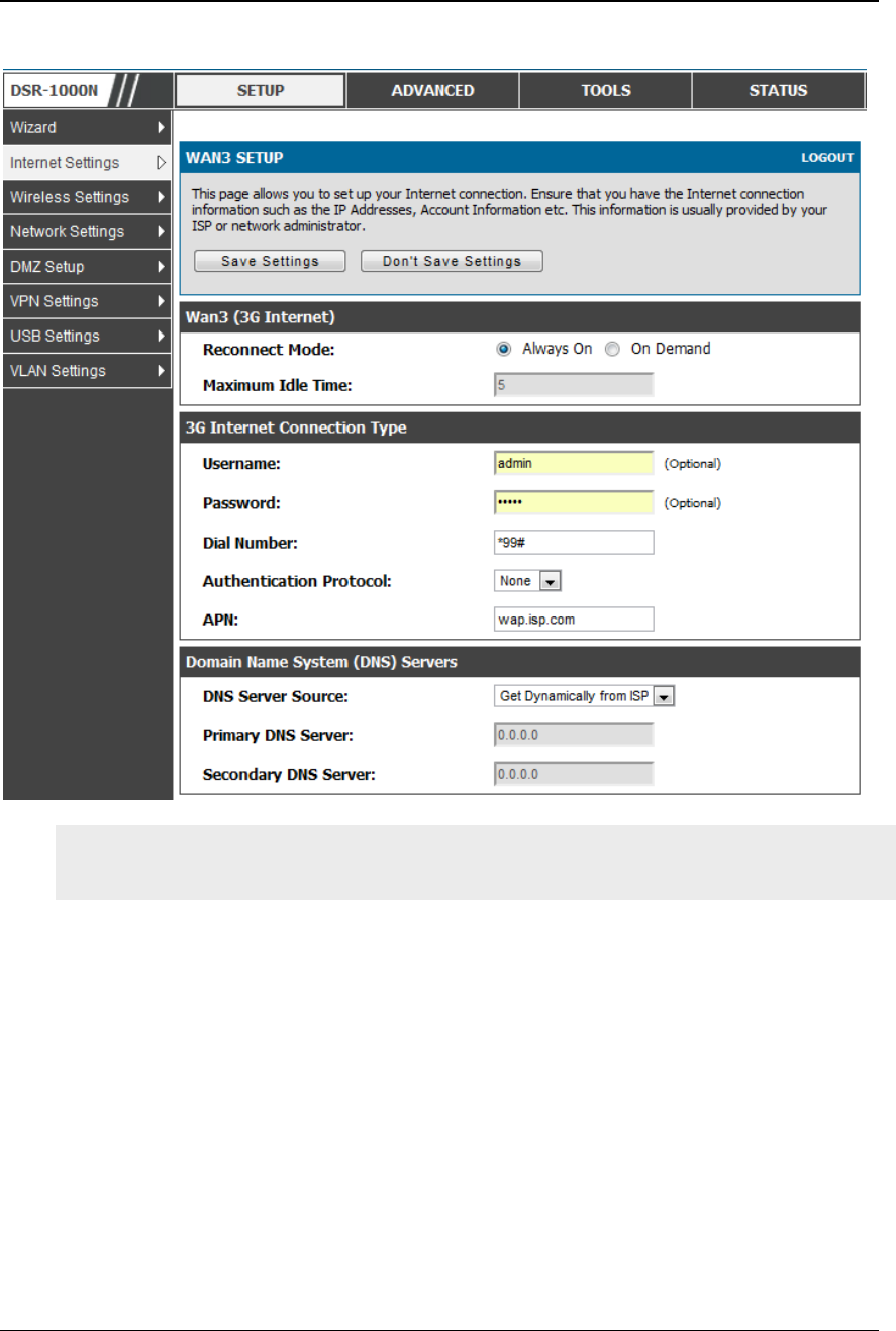
Unified Services Router User Manual
66
Figure 39: WAN3 configuration for 3G internet
3G WAN support is available on these dual WAN products: DSR-1000 and DSR-
1000N.
Cellular 3G internet access is available on WAN 3 via a 3G USB modem for DSR-
1000 and DSR-1000N. The cellular ISP that provides the 3G data plan will provide
the authentication requirements to establish a connection. The dial Number and APN
are specific to the cellular carriers. Once the connection type settings are configured
and saved, navigate to the WAN status page (Setup > Internet Settings > WAN3
Status) and Enable the WAN3 link to establish the 3G connection.
3.8 WAN Port Settings
Advanced > Advanced Network > WAN Port Setup
The physical port settings for each WAN link can be defined here. If your ISP account
defines the WAN port speed or is associated with a MAC address, this information is
required by the router to ensure a smooth connection with the network.
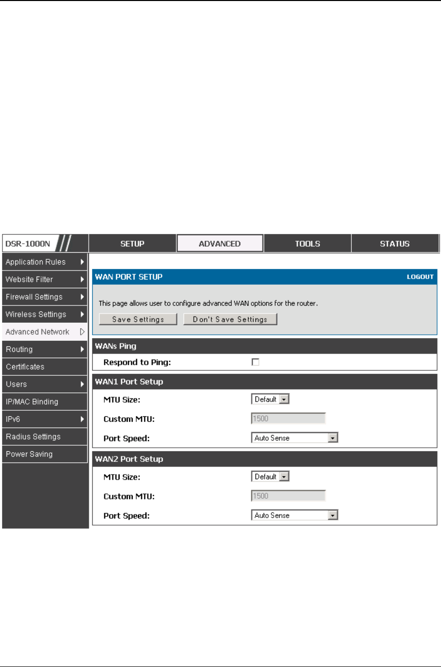
Unified Services Router User Manual
67
The default MTU size supported by all ports is 1500. This is the largest packet size
that can pass through the interface without fragmentation. This size can be increased,
however large packets can introduce network lag and bring down the interface speed.
Note that a 1500 byte size packet is the largest allowed by the Ethernet protocol at the
network layer.
The port speed can be sensed by the router when Auto is selected. With this option the
optimal port settings are determined by the router and network. The duplex (half or
full) can be defined based on the port support, as well as one of three port speeds: 10
Mbps, 100 Mbps and 1000 Mbps (i.e. 1 Gbps). The default setting is 100 Mbps for all
ports.
The default MAC address is defined during the manufacturing process for the
interfaces, and can uniquely identify this router. You can customize each WAN port’s
MAC address as needed, either by letting the WAN port assume the current LAN
host’s MAC address or by entering a MAC address manually.
Figure 40: Physical WAN port settings

Unified Services Router User Manual
68
Chapter 4. Wireless Access Point
Setup
This router has an integrated 802.11n radio that allows you to create an access point for
wireless LAN clients. The security/encryption/aut hentication options are grouped in a
wireless Profile, and each configured profile will be available for selection in the AP
configuration menu. The profile defines various parameters for the AP, including the
security between the wireless client and the AP, and can be shared between multiple
APs instances on the same device when needed.
The content in this section is applicable to the DSR-500N and DSR-1000N
products.
Up to four unique wireless networks can be created by configuring multiple “virtual”
APs. Each such virtual AP appears as an independent AP (unique SSID) to supported
clients in the environment, but is actually running on the same physical radio integrated
with this router.
You will need the following information to configure your wireless network:
Types of devices expected to access the wireless network and their supported Wi -
Fi™ modes
The router’s geographical region
The security settings to use for securing the wireless network.
Profiles may be thought of as a grouping of AP parameters that can then be applied
to not just one but multiple AP instances (SSIDs), thus avoiding duplication if the
same parameters are to be used on multiple AP instances or SSIDs.
4.1 Wireless Settings Wizard
Setup > Wizard > Wireless Settings
The Wireless Network Setup Wizard is available for users new to networking. By
going through a few straightforward configuration pages you can enable a Wi -Fi™
network on your LAN and allow supported 802.11 clients to connect to the configured
Access Point.
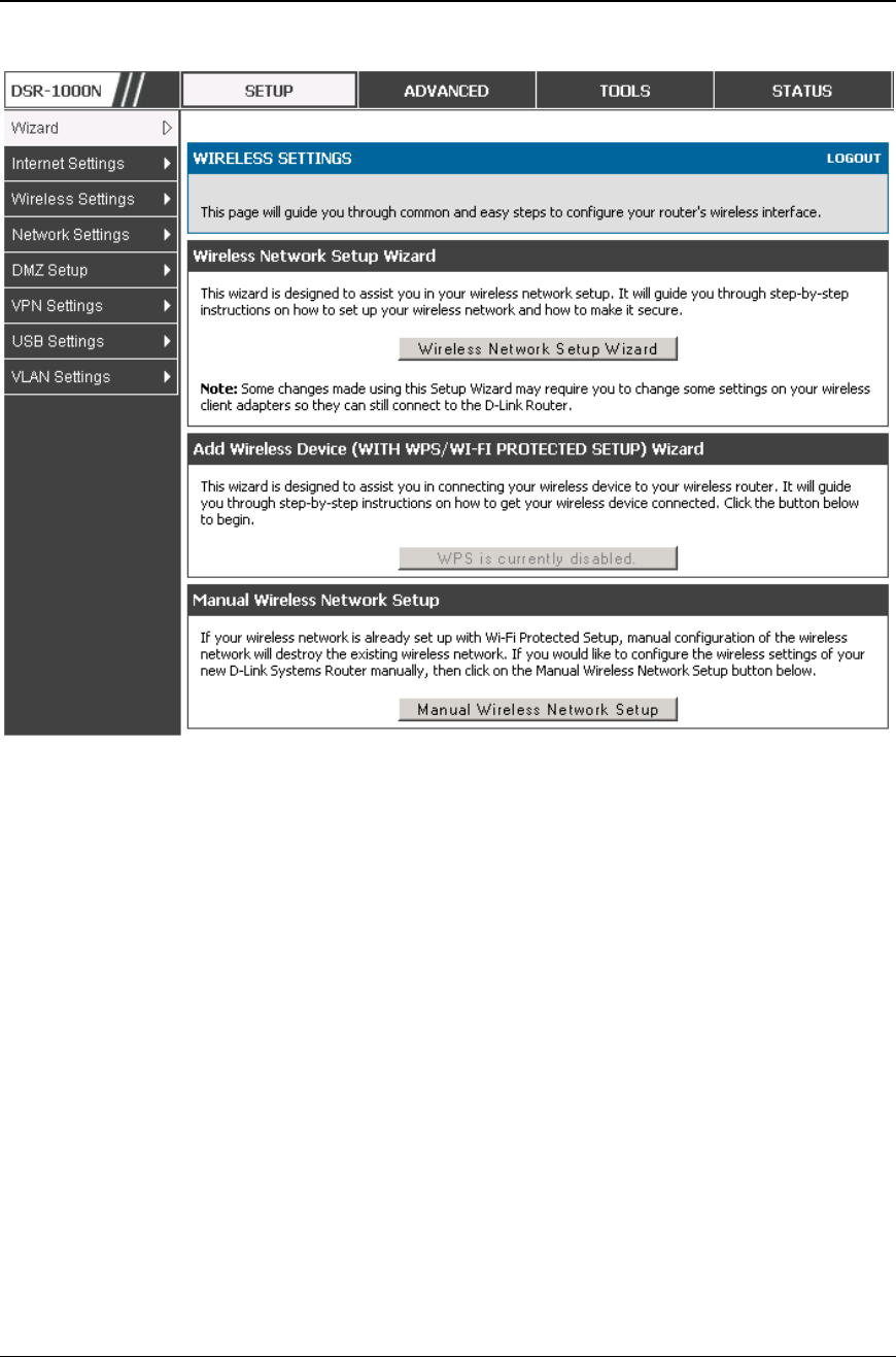
Unified Services Router User Manual
69
Figure 41: Wireless Network Setup Wi za rds
4.1.1 Wireless Network Setup Wizard
This wizard provides a step-by-step guide to create and secure a new access point on
the router. The network name (SSID) is the AP identifier that will be detected by
supported clients. The Wizard uses a TKIP+AES cipher for WPA / WPA2 security;
depending on support on the client side, devices associate with this AP using either
WPA or WPA2 security with the same pre-shared key.
The wizard has the option to automatically generate a network key for the AP. This
key is the pre-shared key for WPA or WPA2 type security. Supported clients that
have been given this PSK can associate with this AP. The default (auto-assigned)
PSK is “passphrase”.
The last step in the Wizard is to click the Connect button, which confirms the
settings and enables this AP to broadcast its availability in the LAN.
4.1.2 Add Wireless Device with WPS
With WPS enabled on your router, the selected access point allows supported WPS
clients to join the network very easily. When the Auto option for connecting a

Unified Services Router User Manual
70
wireless device is chose, you will be presented with two common WPS setup
options:
Personal Identification Number (PIN): The wireless device that supports
WPS may have an alphanumeric PIN, and if entered in this fi eld the AP will
establish a link to the client. Click Connect to complete setup and connect to
the client.
Push Button Configuration (PBC): for wireless devices that support PBC,
press and hold down on this button and within 2 minutes, click the PBC
connect button. The AP will detect the wireless device and establish a link
to the client.
You need to enable at least one AP with WPA/WPA2 security and also enable WPS
in the Advanced > Wireless Settings > WPS page to use the WPS wizard.
4.1.3 Manual Wireless Network Setup
This button on the Wizard page will link to the Setup> Wireless Settings> Access
Points page. The manual options allow you to create new APs or modify the
parameters of APs created by the Wizard.
4.2 Wireless Profiles
Setup > Wireless Settings > Profiles
The profile allows you to assign the security type, encryption and authentication to
use when connecting the AP to a wireless client. The default mode is “open”, i.e. no
security. This mode is insecure as it allows any compatible wireless clients to connect
to an AP configured with this security profile.
To create a new profile, use a unique profile name to identify the combination of
settings. Configure a unique SSID that will be the identifier used by the clients to
communicate to the AP using this profile. By choosing to broadcast the SSID,
compatible wireless clients within range of the AP can detect this profile’s
availability.
The AP offers all advanced 802.11 security modes, including WEP, WPA, WPA2 and
WPA+WPA2 options. The security of the Access point is configured by the Wireless
Security Type section:
Open: select this option to create a public “open” network to allow unauthenticated
devices to access this wireless gateway.
WEP (Wired Equivalent Privacy): this option requires a static (pre -shared) key to
be shared between the AP and wireless client. Note that WEP does not support
802.11n data rates; is it appropriate for legacy 802.11 connections.
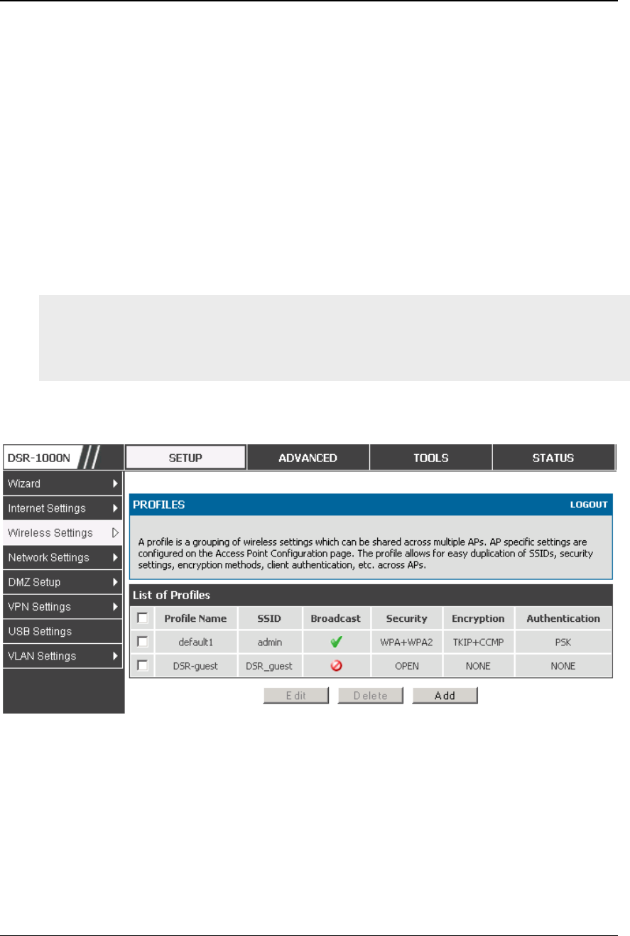
Unified Services Router User Manual
71
WPA (Wi-Fi Protected Access): For stronger wireless security than WEP, choose
this option. The encryption for WPA will use TKIP and also CCMP if required. The
authentication can be a pre-shared key (PSK), Enterprise mode with RADIUS
server, or both. Note that WPA does not support 802.11n data rates; is it
appropriate for legacy 802.11 connections.
WPA2: this security type uses CCMP encryption (and the option to add TKIP
encryption) on either PSK (pre-shared key) or Enterprise (RADIUS Server)
authentication.
WPA + WPA2: this uses both encryption algorithms, TKIP and CCMP. WPA
clients will use TKIP and WPA2 clients will use CCMP encryption algorithms.
“WPA+WPA2” is a security option that allows devices to connect to an AP using
the strongest security that it supports. This mode allows legacy devices that only
support WPA2 keys (such as an older wireless printer) to connect to a secure AP
where all the other wireless clients are using WPA2.
Figure 42: Li st of Available Prof iles show s th e options available t o
secure the wireless li nk
4.2.1 WEP Security
If WEP is the chosen security option, you must set a unique static key to be shared
with clients that wish to access this secured wireless network. This static key can be
generated from an easy-to-remember passphrase and the selected encryption length.
Authentication: select between Op en System, or Shared Key schemes

Unified Services Router User Manual
72
Encryption: select the encryption key size -- 64 bit WEP or 128 bit WEP.
The larger size keys provide stronger encryption, thus making the key more
difficult to crack
WEP Passphrase: enter an alphanumeric phrase and click Generate Key to
generate 4 unique WEP keys with length determined by the encryption key
size. Next choose one of the keys to be used for authentication. The selected
key must be shared with wireless clients to connect to this device.
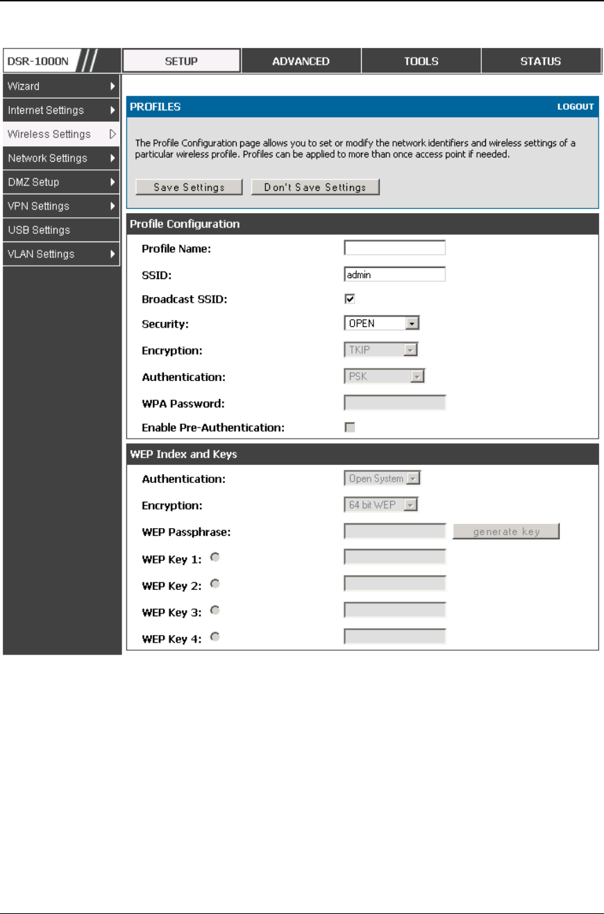
Unified Services Router User Manual
73
Figure 43: Profile configuration to set ne twor k security
4.2.2 WPA or WPA2 with PSK
A pre-shared key (PSK) is a known passphrase configured on the AP and client both
and is used to authenticate the wireless client. An acceptable passphrase is between
8 to 63 characters in length.
4.2.3 RADIUS Authentication
Advanced > RADIUS Settings
Enterprise Mode uses a RADIUS Server for WPA and/or WPA2 security. A
RADIUS server must be configured and accessible by the router to authenticate

Unified Services Router User Manual
74
wireless client connections to an AP enabled with a profile that uses RADIUS
authentication.
The Authentication IP Address is required to identify the server. A
secondary RADIUS server provides redundancy in the event that the primary
server cannot be reached by the router when needed.
Authentication Port: the port for the RADIUS server connection
Secret: enter the shared secret that allows this router to log into the
specified RADIUS server(s). This key must match the shared secret on the
RADIUS Server.
The Timeout and Retries fields are used to either move to a secondary server
if the primary cannot be reached, or to give up the RADIUS authentication
attempt if communication with the server is not possible.
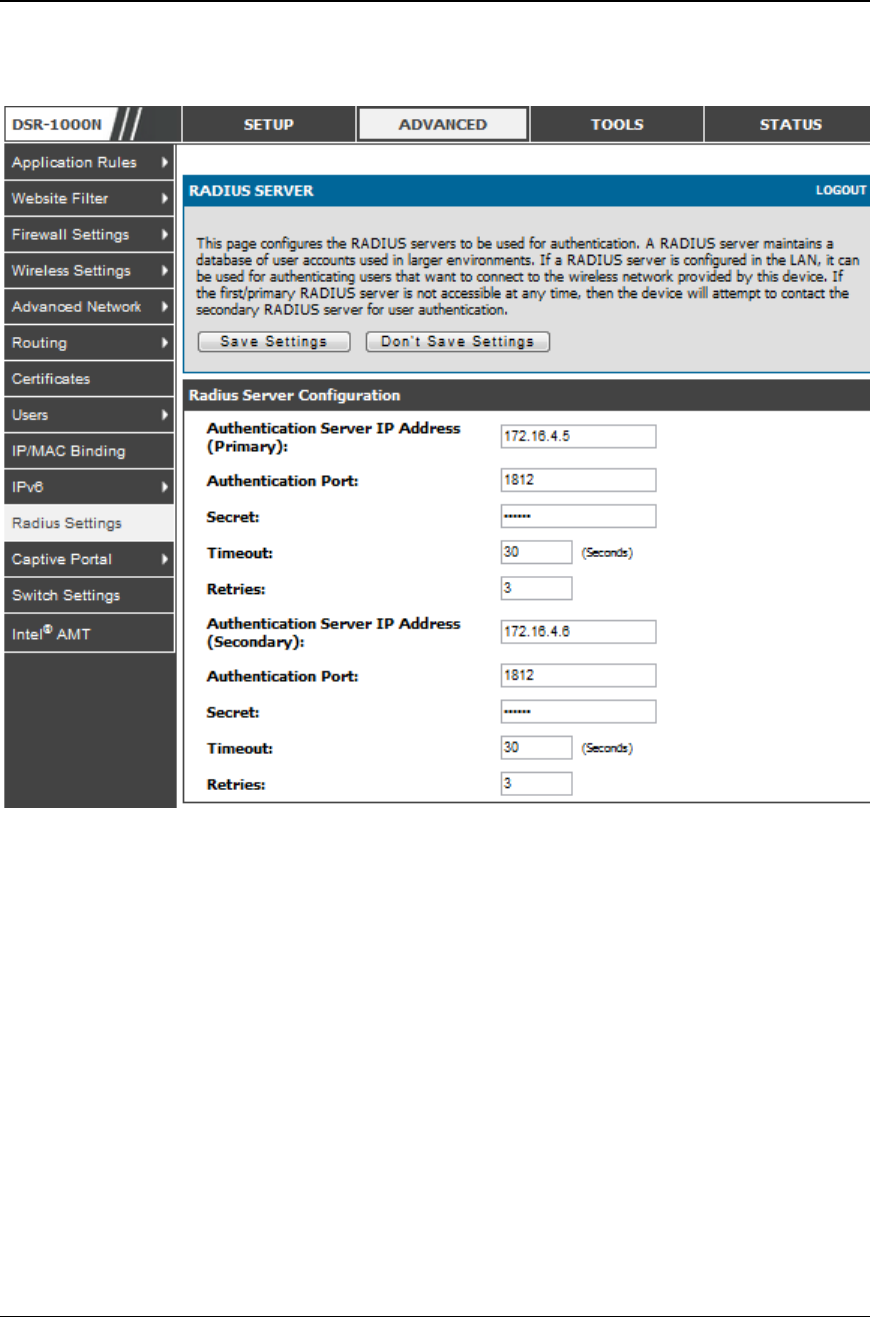
Unified Services Router User Manual
75
Figure 44: RADIUS server (External Authentication) co nfigur ation
4.3 Creating and Using Access Points
Setup > Wireless Settings > Access Points
Once a profile (a group of security settings) is created, it can be assigned to an AP on
the router. The AP SSID can be configured to broadcast its availability to the 802.11
environment can be used to establish a WLAN network.
The AP configuration page allows you to create a new AP and link to it one of the
available profiles. This router supports multiple AP’s referred to as virtual access
points (VAPs). Each virtual AP that has a unique SSIDs appears as an independent
access point to clients. This valuable feature allows the router’s radio to be
configured in a way to optimize security and throughput for a group of clients as
required by the user. To create a VAP, click the “add” button on the Setup >
Wireless Settings > Access Points page. After setting the AP name, the profile
dropdown menu is used to select one of the configured profiles.
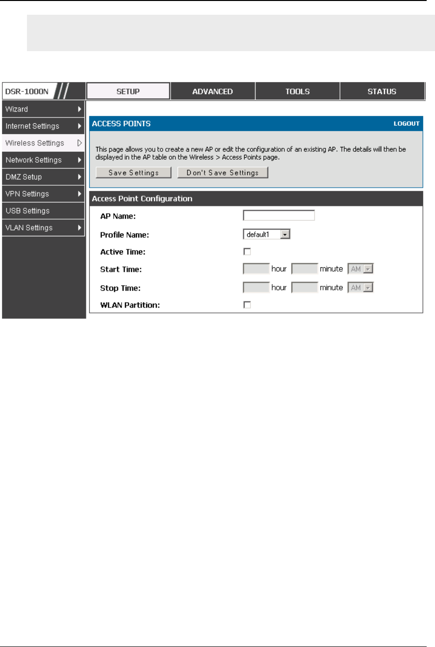
Unified Services Router User Manual
76
The AP Name is a unique identifier used to manage the AP from the GUI, and is
not the SSID that is detected by clients when the AP has broadcast enabled.
Figure 45: Virtual AP configuration
A valuable power saving feature is the start and stop time control for this AP. You
can conserve on the radio power by disabling the AP when it is not in use. For
example on evenings and weekends if you know there are no wireless clients, the start
and stop time will enable/disable the access point automatically.
Once the AP settings are configured, you must enable the AP on the radio on the
Setup > Wireless Settings > Access Points page. The status field changes to
“Enabled” if the AP is available to accept wireless clients. If the AP is configured to
broadcast its SSID (a profile parameter), a green check mark indicating it is
broadcasting will be shown in the List of Available Access points.
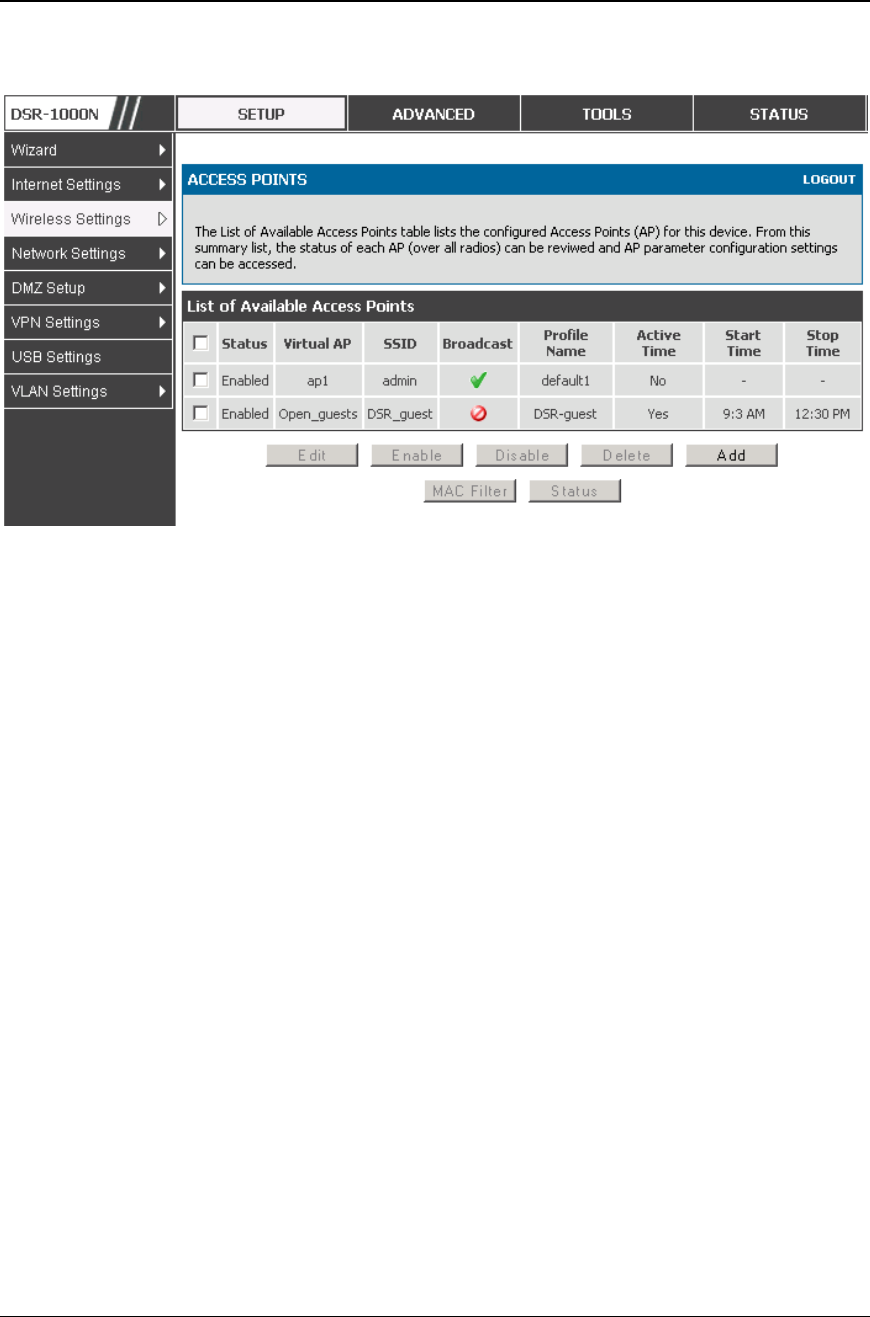
Unified Services Router User Manual
77
Figure 46: Li st of configured access points (Virt ual APs) shows one
enabled access poi nt on the radi o, broadcasting its SSID
The clients connected to a particular AP can be viewed by using the Status Button on
the List of Available Access Points. Traffic statistics are shown for that individual
AP, as compared to the summary stats for each AP on the Statistics table. Connected
clients are sorted by the MAC address and indicate the security parameters used by
the wireless link, as well as the time connected to this particular AP. Clicking the
Details button next to the connected client will give the detailed send and receive
traffic statistics for the wireless link between this AP and the client.
4.3.1 Primary benefits of Virtual APs:
Optimize throughput: if 802.11b, 802.11 g, and 802.11n clients are expected
to access the LAN via this router, creating 3 VAPs will allow you to manage
or shape traffic for each group of clients. A unique SSID can be created for
the network of 802.11b clients and another SSID can be assigned for the
802.11n clients. Each can have different security parameters – remember,
the SSID and security of the link is determined by the profile. In this way
legacy clients can access the network without bringing down the overall
throughput of more capable 802.11n clients.
Optimize security: you may wish to support select legacy clients that only
offer WEP security while using WPA2 security for th e majority of clients
for the radio. By creating two VAPs configured with different SSIDs and
different security parameters, both types of clients can connect to the LAN.
Since WPA2 is more secure, you may want to broadcast this SSID and not
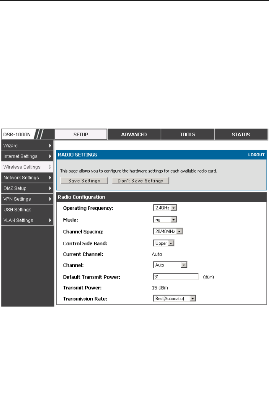
Unified Services Router User Manual
78
broadcast the SSID for the VAP with WEP since it is meant to be used for a
few legacy devices in this scenario.
4.4 Tuning Radio Specific Settings
Setup > Wireless Settings > Radio Settings
The Radio Settings page lets you configure t he channels and power levels available
for the AP’s enabled on the DSR. The router has a dual band 802.11n radio, meaning
either 2.4 GHz or 5 GHz frequency of operation can be selected (not concurrently
though). Based on the selected operating frequency, the mode selection will let you
define whether legacy connections or only 802.11n connections (or both) are accepted
on configured APs.
Figure 47: Radio card configuratio n options
The ratified 802.11n support on this radio requires selecting the appropriate broadcast
(NA or NG etc.) mode, and then defining the channel spacing and control side band
for 802.11n traffic. The default settings are appropriate for most networks. For
example, changing the channel spacing to 40 MHz can improve bandwidth at the
expense of supporting earlier 802.11n clients.
The available transmission channels are governed by regulatory constraints based on
the region setting of the router. The maximum transmission power is similarly
governed by regulatory limits; you have the option to decreas e from the default
maximum to reduce the signal strength of traffic out of the radio.
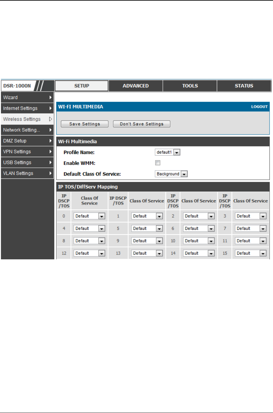
Unified Services Router User Manual
79
4.5 WMM
Setup > Wireless Settings > WMM
Wi-Fi Multimedia (WMM) provides basic Quality of service (QoS) features to IEEE
802.11 networks. WMM prioritizes traffic according t o four Access Categories (AC) -
voice, video, best effort, and background.
Figure 48: Wi-Fi Multimedia
Profile Name:
This field allows you to select the available profiles in wireless settings .
Enable WMM:
This field allows you to enable WMM to improve multimedia transmission.
Default Class Of Service:
This field allows you to select the available Access Categories (voice, video, best
effort, and background).
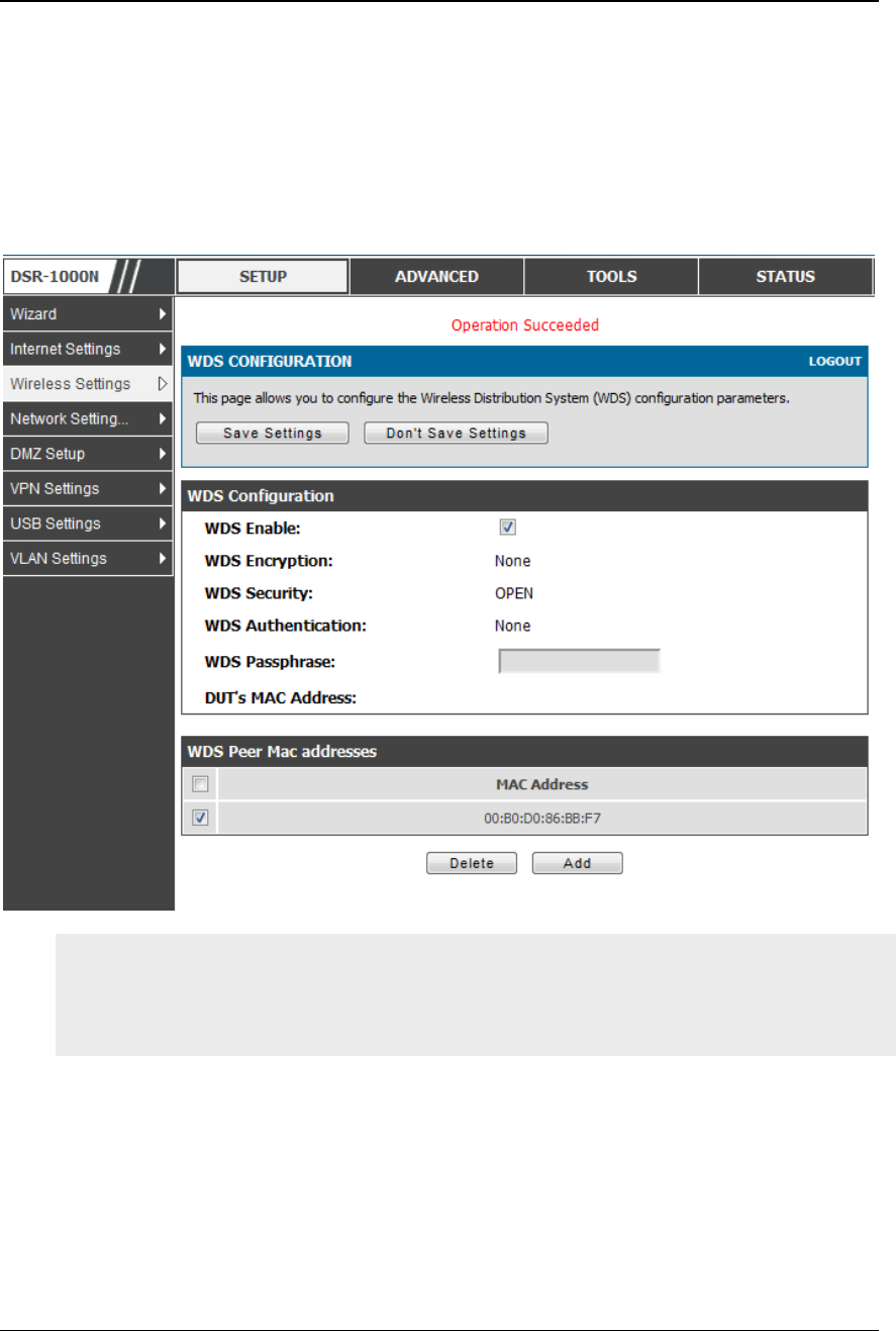
Unified Services Router User Manual
80
4.6 Wireless distribution system (WDS)
Setup > Wireless Settings > WDS
Wireless distribution system is a system enabling the wireless interconnection of
access points in a network. This feature is only guaranteed to work only between
devices of the same type.
Figure 49: Wireless Distri butio n Syste m
This feature is only guaranteed to work only between devices of the same type (i.e.
using the same chipset/driver). For example between two DSR250N boxes, or
between two DSR1000N. It should also interoperate between a DSR 1000N and
DSR 500 N boxes since they are based on the same chipset/driver.
When the user enables the WDS links use the same security configuration as the
default access point. The WDS links do not have true WPA/WPA2 support, as in there
is no WPA key handshake performed. Instead the Session Key to be used with a WDS
Peer is computed using a hashing function (similar to the one used for computing a
WPA PMK). The inputs to this function are a PSK (configurable by an administrator
from the WDS page) and an internal "magic" string (non-configurable).
In effect the WDS links use TKIP/AES encryption, depending on the encryption
configured for the default AP. In case the default AP use s mixed encryption (TKIP +
AES).The WDS link will use the AES encryption scheme.

Unified Services Router User Manual
81
For a WDS link to function properly the Radio settings on the WDS peers have to
be the same.
The WDS page would consist of two sections. The first section provides general WDS
settings shared by all its WDS peers.
WDS Enable - This would be a check box
WDS Encryption - Displays the type of encryption used. It could be one of OPEN/64
bit WEP/128 bit WEP/TKIP/AES (Use the term being used throughout the box i.e.
either CCMP or AES).
WDS Passphrase - This is required if the encryption selected is TKIP/CCMP. We
would expect it to be within 8~63 ASCII characters. In the WDS configuration page
this field is mandatory and has to be same on the two WDS peers, when the security is
configured in TKIP/AES mode. The WDS links use this as the PSK for the
connection.
DUT's Mac Address - This would be the mac address of this box. This should be
configured in the peer's WDS configuration page to be able to establish a WDS link
with this box. This field in the WDS Configuration section displays the device's mac
address, which needs to be specified on the WDS pe er for making a connection to this
device (Similarly the WDS peers MAC address will have to be specified on this
device for the WDS link to be established between the two devices).
The second section will have the list of configured WDS peers with buttons to
Add/Delete Peer entries. We support up to a maximum of 4 WDS links per box.
The both devices need to have same wireless settings (wireless mode, encryption,
authentication method, WDS passphrase, WDS MAC address and wireless SSID)
when we configure WDS features in DSR router.
The "Add WDS Peer" section allows the user to specify a WDS peer. The "WDS
Peers" table displays the list of WDS peers currently configured on the device. A
maximum of 4 WDS peers can be specified in any given mode.
4.7 Advanced Wireless Settings
Advanced > Wireless Settings > Advanced Wireless
Sophisticated wireless administrators can modify the 802.11 communication
parameters in this page. Generally, the default settings are appropriate for most
networks. Please refer to the GUI integrated help text for further details on the use of
each configuration parameter.

Unified Services Router User Manual
82
Figure 50: Adv anced Wireless communication settings
4.8 Wi-Fi Protected Setup (WPS)
Advanced > Wireless Settings > WPS
WPS is a simplified method to add supporting wireless clients to the network. WPS is
only applicable for APs that employ WPA or WPA2 security. To use WPS, select the
eligible VAPs from the dropdown list of APs that have been configured with this
security and enable WPS status for this AP.
The WPS Current Status section outlines the security, authentication, and encryption
settings of the selected AP. These are consistent with the AP’s profile. There are two
setup options available for :
Personal Identification Number (PIN): The wireless device that supports WPS
may have an alphanumeric PIN, if so add the PIN in this field. The router will
connect within 60 seconds of clicking the “Configure via PIN” button immediately
below the PIN field. There is no LED indication that a client has connected.
Push Button Configuration (PBC): for wireless devices that support PBC, press
and hold down on this button and within 2 minutes click the PBC connect button.
The AP will detect the wireless device and establish a link to the client.
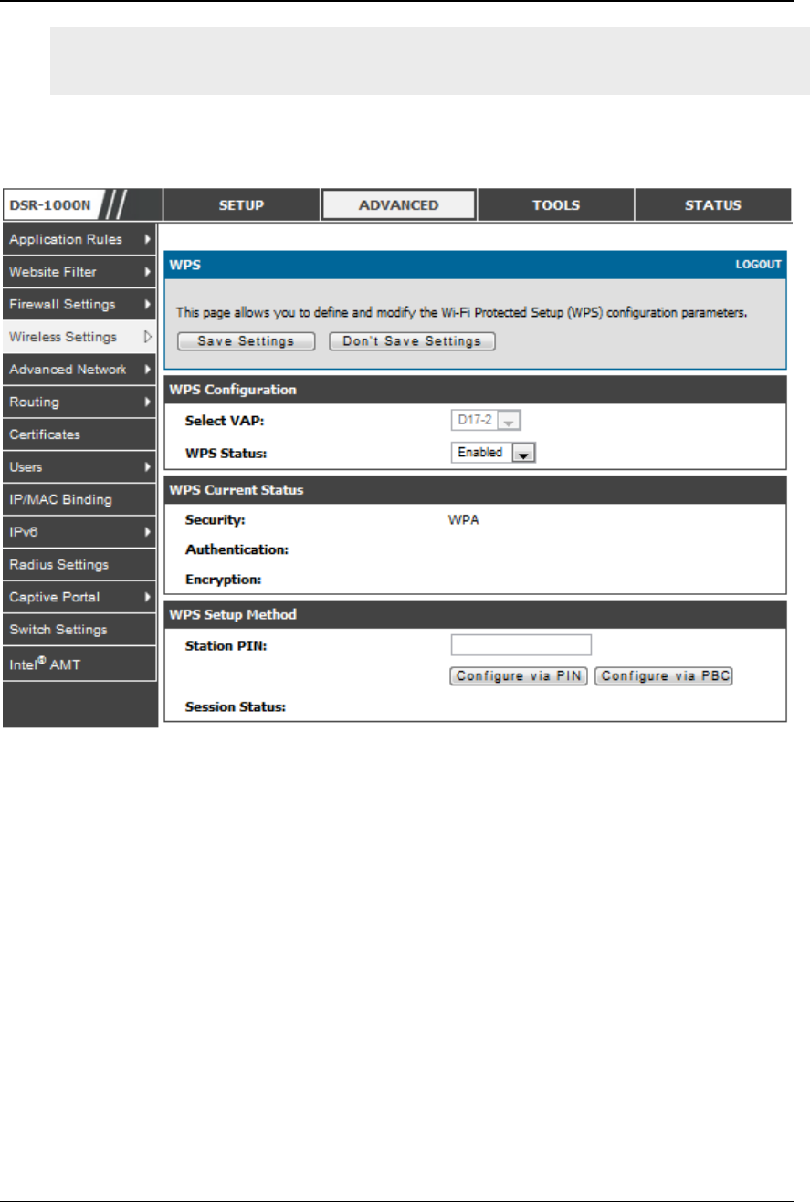
Unified Services Router User Manual
83
More than one AP can use WPS, but only one AP can be used to establish WPS
links to client at any given time.
Figure 51: WP S configuration f or an AP with WPA/WP A2 profile

Chapter 5. Securing the Private
Network
You can secure your network by creating and applying rules that your router uses to
selectively block and allow inbound and outbound Internet traffic. You then specify
how and to whom the rules apply. To do so, you must define the following:
Services or traffic types (examples: web browsing, VoIP, other standard services
and also custom services that you define)
Direction for the traffic by specifying the source and destination of traffic ; this is
done by specifying the “From Zone” (LAN/WAN/DMZ) and “To Zone”
(LAN/WAN/DMZ)
Schedules as to when the router should apply rules
Any Keywords (in a domain name or on a URL of a web page) that the router
should allow or block
Rules for allowing or blocking inbound and outbound Internet traffic for specified
services on specified schedules
MAC addresses of devices that should not access the internet
Port triggers that signal the router to allow or block access to specified services as
defined by port number
Reports and alerts that you want the router to send to you
You can, for example, establish restricted-access policies based on time-of-day, web
addresses, and web address keywords. You can block Internet access by applications
and services on the LAN, such as chat rooms or games. You can block just certain
groups of PCs on your network from being accessed by the WAN or public DMZ
network.
5.1 Firewall Rules
Advanced > Firewall Settings > Firewall Rules
Inbound (WAN to LAN/DMZ) rules restrict access to traffic entering your network,
selectively allowing only specific outside users to access specific local resou rces. By
default all access from the insecure WAN side are blocked from accessing the secure
LAN, except in response to requests from the LAN or DMZ. To allow outside devices
to access services on the secure LAN, you must create an inbound firewall rule for
each service.
If you want to allow incoming traffic, you must make the router’s WAN port IP
address known to the public. This is called “exposing your host.” How you make your
address known depends on how the WAN ports are configured; for this router you
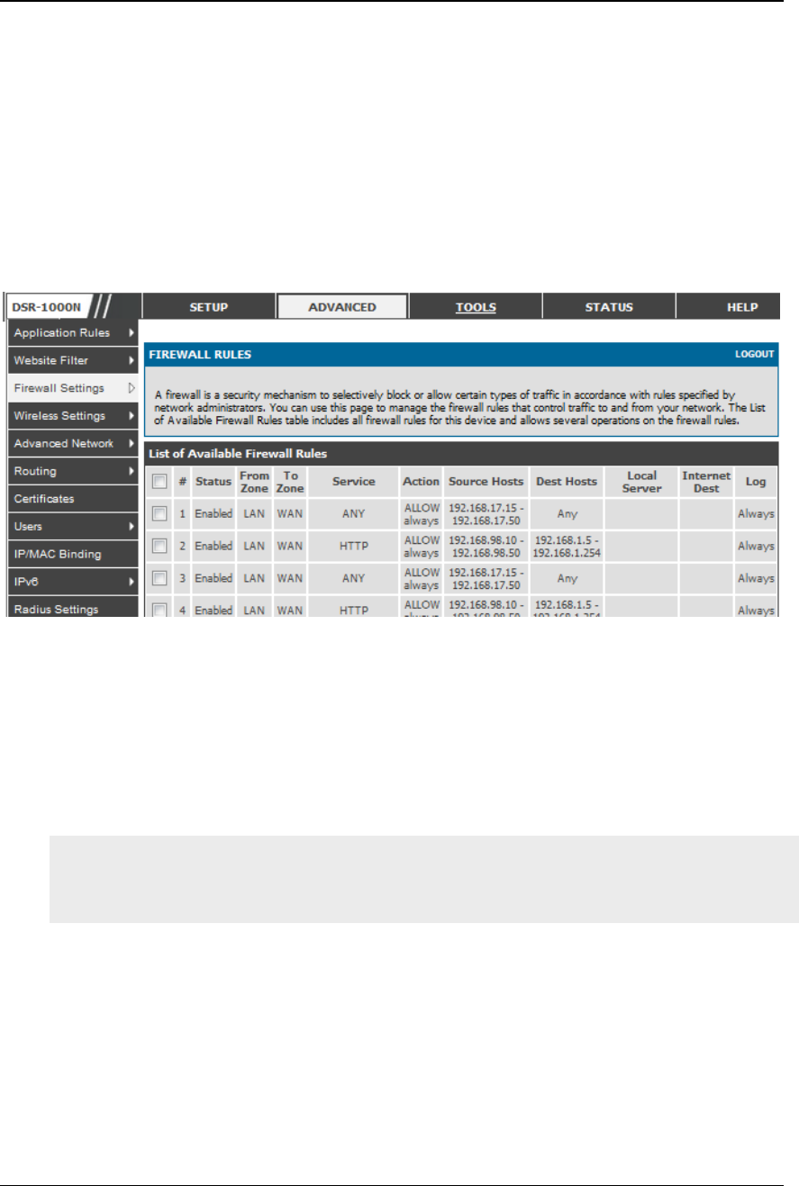
Unified Services Router User Manual
86
may use the IP address if a static address is assigned to the WAN port, or if your
WAN address is dynamic a DDNS (Dynamic DNS) name can be used.
Outbound (LAN/DMZ to WAN) rules restrict access to traffic leaving your network,
selectively allowing only specific local users to access specific outside resources. The
default outbound rule is to allow access from the secure zone (LAN) to either the
public DMZ or insecure WAN. On other hand the default outbound rule is to deny
access from DMZ to insecure WAN. You can change this default behaviour in the
Firewall Settings > Default Outbound Policy page. When the default outbound
policy is allow always, you can to block hosts on the LAN from accessing internet
services by creating an outbound firewall rule for each service.
Figure 52: List of Available Firewall Rules
5.2 Defining Rule Schedules
Tools > Schedules
Firewall rules can be enabled or disabled automatically if they are associated with a
configured schedule. The schedule configuration page allows you to define days of
the week and the time of day for a new schedule, and then this schedule can be
selected in the firewall rule configuration page.
All schedules will follow the time in the routers configured time zone. Refer to the
section on choosing your Time Zone and configuring NTP servers for more
information.
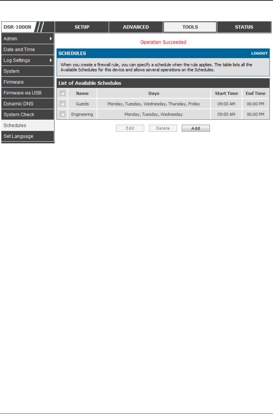
Unified Services Router User Manual
87
Figure 53: Li st of Available Schedules t o bind to a firewall rule
5.3 Configuring Firewall Rules
Advanced > Firewall Settings > Firewall Rules
All configured firewall rules on the router are displayed in the Firewall Rules list.
This list also indicates whether the rule is enabled (active) or not, and gives a
summary of the From/To zone as well as the services or users that the rule affects.
To create a new firewall rules, follow the steps below:
1. View the existing rules in the List of Available Firewall Rules table.
2. To edit or add an outbound or inbound services rule, do the following:
To edit a rule, click the checkbox next to the rule and click E dit to reach that rule’s
configuration page.
To add a new rule, click Add to be taken to a new rule’s configuration page. Once
created, the new rule is automatically added to the original table.
3. Chose the From Zone to be the source of originating traffic: either the secure LAN, public
DMZ, or insecure WAN. For an inbound rule WAN should be selected as the From Zone.
4. Choose the To Zone to be the destination of traffic covered by this rule. If the From Zone
is the WAN, the to Zone can be the public DMZ or secure LAN. Similarly if the From
Zone is the LAN, then the To Zone can be the public DMZ or insecure WAN.
5. Parameters that define the firewall rule include the following:

Unified Services Router User Manual
88
Service: ANY means all traffic is affected by this rule. For a specific
service the drop down list has common services, or you can select a
custom defined service.
Action & Schedule: Select one of the 4 actions that this rule defines:
BLOCK always, ALLOW always, BLOCK by schedule otherwise
ALLOW, or ALLOW by schedule otherwise BLOCK . A schedule must
be preconfigured in order for it to be available in the dropdown list to
assign to this rule.
Source & Destination users: For each relevant category, select the users
to which the rule applies:
Any (all users)
Single Address (enter an IP address)
Address Range (enter the appropriate IP address range)
Log: traffic that is filtered by this rule can be logged; this requires
configuring the router’s logging feature separately.
QoS Priority: Outbound rules (where To Zone = insecure WAN only)
can have the traffic marked with a QoS priority tag. Select a priority
level:
Normal-Service: ToS=0 (lowest QoS)
Minimize-Cost: ToS=1
Maximize-Reliability: ToS=2
Maximize-Throughput: ToS=4
Minimize-Delay: ToS=8 (highest QoS)
6. Inbound rules can use Destination NAT (DNAT) for managing traffic from the WAN.
Destination NAT is available when the To Zone = DMZ or secure LAN.
With an inbound allow rule you can enter the internal server address
that is hosting the selected service.
You can enable port forwarding for an incoming service specific rule
(From Zone = WAN) by selecting the appropriate checkbox. This will
allow the selected service traffic from the internet to reach the
appropriate LAN port via a port forwarding rule.
Translate Port Number: With port forwarding, the incoming traffic to
be forwarded to the port number entered here.

Unified Services Router User Manual
89
External IP address: The rule can be bound to a specific WAN interface
by selecting either the primary WAN or configurable port WAN as the
source IP address for incoming traffic.
This router supports multi-NAT and so the External IP address does not necessarily
have to be the WAN address. On a single WAN interface, multiple public IP
addresses are supported. If your ISP assigns you more than one public IP address,
one of these can be used as your primary IP address on the WAN port, and the
others can be assigned to servers on the LAN or DMZ. In this way the LAN/DMZ
server can be accessed from the internet by its aliased public IP address.
7. Outbound rules can use Source NAT (SNAT) in order to map (bind) all LAN/DMZ traffic
matching the rule parameters to a specific WAN interface or external IP address (usually
provided by your ISP).
Once the new or modified rule parameters are saved, it appears in the master list of
firewall rules. To enable or disable a rule, click the checkbox next to the rule in the
list of firewall rules and choose Enable or Disable.
The router applies firewall rules in the order listed. As a general rule, you should
move the strictest rules (those with the most specific services or addresses) to the
top of the list. To reorder rules, click the checkbox next to a rule and click up or
down.
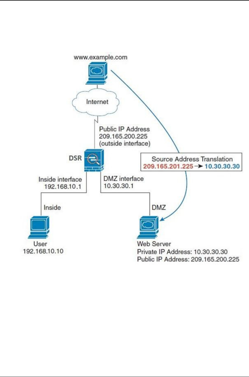
Unified Services Router User Manual
90
Figure 54: Ex ample where an out bo und SNAT rule is used to map an
external IP address (209.156.200.225) to a private DMZ IP
address (10.30.30. 30 )
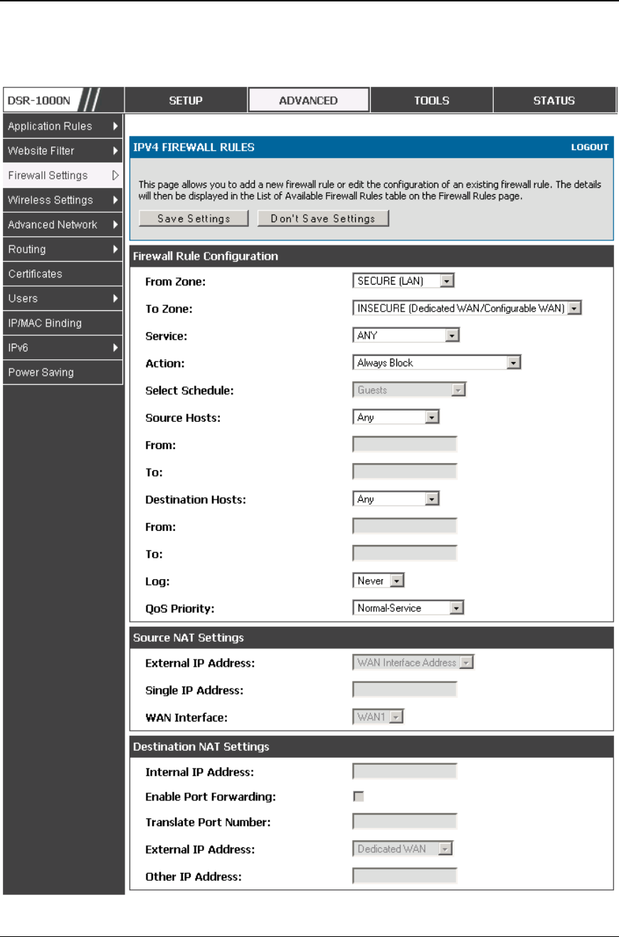
Unified Services Router User Manual
91
Figure 55: The f irewall rule co nfiguration page all ows you to define t he
To/Fro m zone, servi ce, action, schedule s, and specify
so urce/destination IP addresses as nee de d.
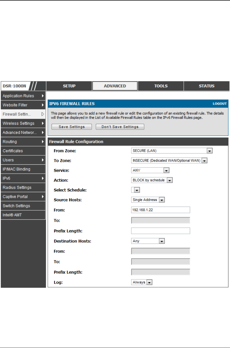
Unified Services Router User Manual
92
5.4 Configuring IPv6 Firewall Rules
Advanced > Firewall Settings > IPv6 Firewall Rules
All configured IPv6 firewall rules on the router are displayed in the Firewall Rules
list. This list also indicates whether the rule is enabled (active) or not, and gives a
summary of the From/To zone as well as the services or users that the rule affects.
Figure 56: The IPv6 firewall rule configuration page allows you to define
the To/From zone, service, action, sche dules, and specify
so urce/destination IP addres ses as nee ded.
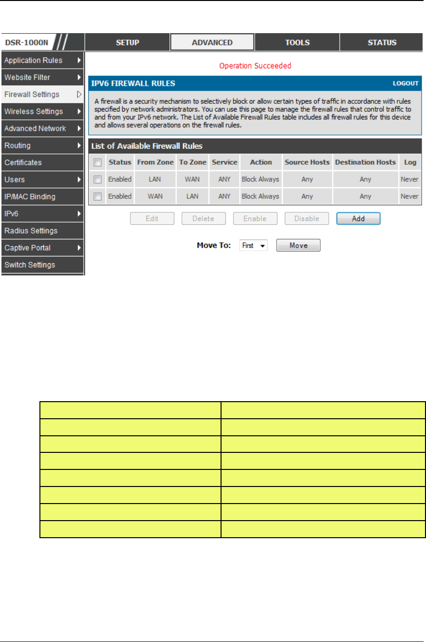
Unified Services Router User Manual
93
Figure 57: List of Available IPv6 Firewall Rule s
5.4.1 Firewall Rule Configuration Examples
Example 1: Allow inbound HTTP traffic to the DMZ
Situation: You host a public web server on your local DMZ network. You want to
allow inbound HTTP requests from any outside IP address to the IP address of your
web server at any time of day.
Solution: Create an inbound rule as follows.
Parameter
Value
From Zone
Insecure (WAN1/WAN2/WAN3)
To Zone
Public (DMZ)
Service
HTTP
Action
ALLOW always
Send to Local Server (DNAT IP)
192.168.5.2 (web server IP address)
Destination Users
Any
Log
Never
Example 2: Allow videoconferencing from range of outside IP addresses
Situation: You want to allow incoming videoconferencing to be ini tiated from a
restricted range of outside IP addresses (132.177.88.2 - 132.177.88.254), from a
branch office.

Unified Services Router User Manual
94
Solution: Create an inbound rule as follows. In the example, CUSeeMe (the video
conference service used) connections are allowed only from a speci fied range of
external IP addresses.
Parameter
Value
From Zone
Insecure (WAN1/WAN2/WAN3)
To Zone
Secure (LAN)
Service
CU-SEEME:UDP
Action
ALLOW always
Send to Local Server (DNAT IP)
192.168.10.11
Destination Users
Address Range
From
132.177.88.2
To
134.177.88.254
Enable Port Forwarding
Yes (enabled)
Example 3: Multi-NAT configuration
Situation: You want to configure multi -NAT to support multiple public IP
addresses on one WAN port interface.
Solution: Create an inbound rule that configures the firewall to host an additional
public IP address. Associate this address with a web server on the DMZ. If you
arrange with your ISP to have more than one public IP address for your use, you can
use the additional public IP addresses to map to servers on yo ur LAN. One of these
public IP addresses is used as the primary IP address of the router. This address is
used to provide Internet access to your LAN PCs through NAT. The other addresses
are available to map to your DMZ servers.
The following addressing scheme is used to illustrate this procedure:
WAN IP address: 10.1.0.118
LAN IP address: 192.168.10.1; subnet 255.255.255.0
Web server host in the DMZ, IP address: 192.168.12.222
Access to Web server: (simulated) public IP address 10.1.0.52
Parameter
Value
From Zone
Insecure (WAN1/WAN2/WAN3)
To Zone
Public (DMZ)
Service
HTTP
Action
ALLOW always
Send to Local Server (DNAT IP)
192.168.12.222 ( web server local IP address)
Destination Users
Single Address

Unified Services Router User Manual
95
E
x
a
m
p
le 4: Bloc
Example 4: Block traffic by schedule if generated from specific range of machines
Use Case: Block all HTTP traffic on the weekends if the request originates from a
specific group of machines in the LAN having a known range of IP addresses, and
anyone coming in through the Network from the WAN (i.e. all remote users).
Configuration:
1. Setup a schedule:
To setup a schedule that affects traffic on weekends only, navigate to Security:
Schedule, and name the schedule “Weekend”
Define “weekend” to mean 12 am Saturday morning to 12 am Monday morning
– all day Saturday & Sunday
In the Scheduled days box, check that you want the schedule to be active for
“specific days”. Select “Saturday” and “Sunday”
In the scheduled time of day, select “all day” – this will apply the schedule
between 12 am to 11:59 pm of the selected day.
Click apply – now schedule “Weekend” isolates all day Saturday and Sunday
from the rest of the week.
From
10.1.0.52
WAN Users
Any
Log
Never
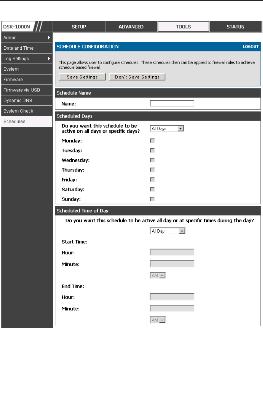
Unified Services Router User Manual
96
Figure 58: Schedule configuration for the above example.
2. Since we are trying to block HTTP requests, it is a service with To Zone: Insecure
(WAN1/WAN2/WAN3) that is to be blocked according to schedule “Weekend”.

Unified Services Router User Manual
97
3. Select the Action to “Block by Schedule, otherwise allow”. This will take a predefined
schedule and make sure the rule is a blocking rule during the defined dates/times. All
other times outside the schedule will not be affected by this firewall blocking rule
4. As we defined our schedule in schedule “Weekend”, this is available in the dropdown
menu
5. We want to block the IP range assigned to the marketing group. Let’s say they have IP
192.168.10.20 to 192.168.10.30. On the Source Users dropdown, select Address Range
and add this IP range as the from and To IP addresses.
6. We want to block all HTTP traffic to any services going to the insecure zone. The
Destination Users dropdown should be “any”.
7. We don’t need to change default QoS priority or Logging (unless desired) – clicking apply
will add this firewall rule to the list of firewall rules.
8. The last step is to enable this firewall rule. Select the rule, and click “enable” below the
list to make sure the firewall rule is active
5.5 Security on Custom Services
Advanced > Firewall Settings > Custom Services
Custom services can be defined to add to the list of services available during firewall
rule configuration. While common services have known TCP/UDP/ICMP ports for
traffic, many custom or uncommon applications exist in the LAN or WAN. In the
custom service configuration menu you can define a range of ports and identi fy the
traffic type (TCP/UDP/ICMP) for this service. Once defined, the new service will
appear in the services list of the firewall rules configuration menu.
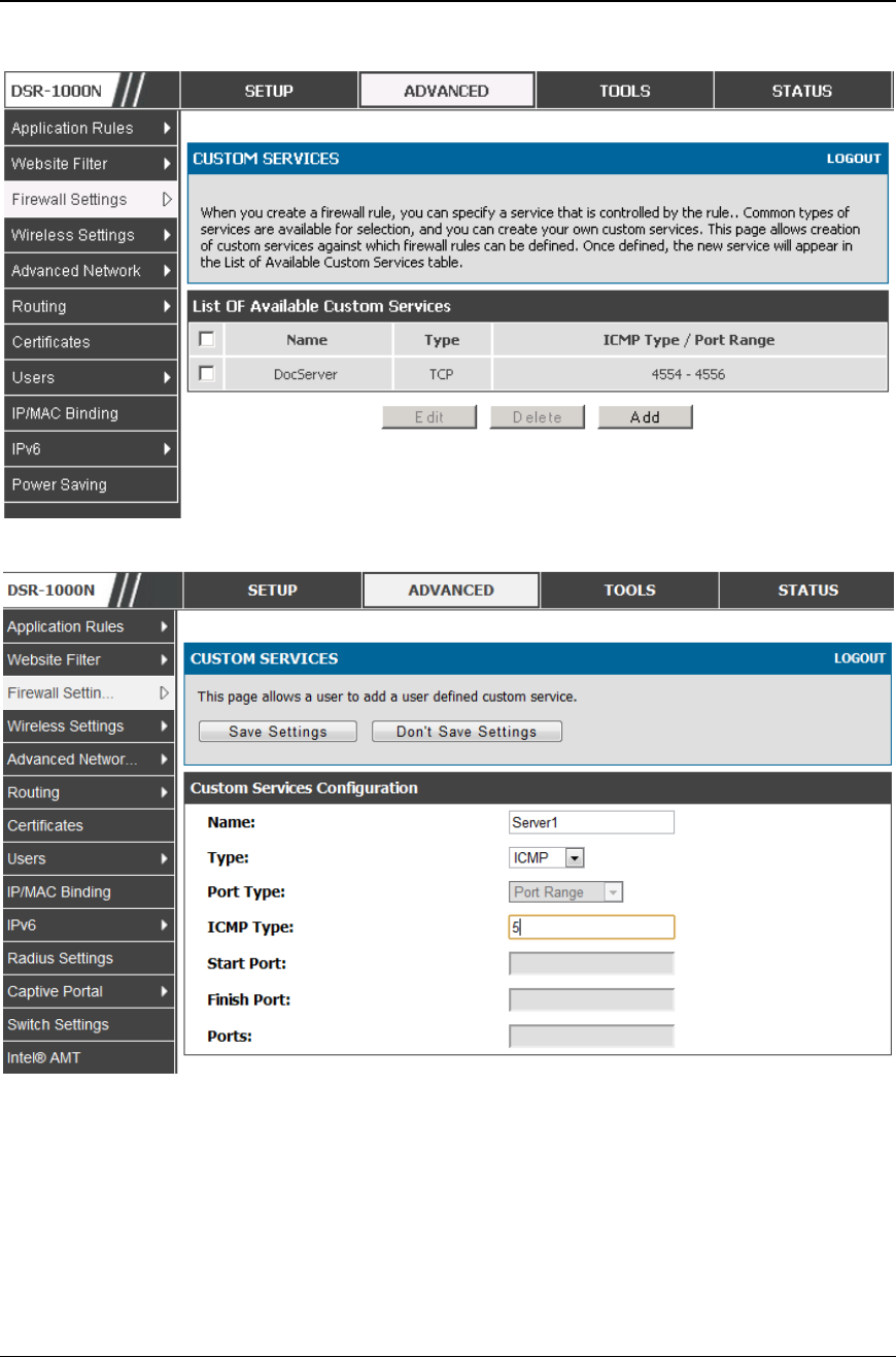
Unified Services Router User Manual
98
Figure 59: Li st of user defined services .
Figure 60: Custo m Services configuration
Created services are available as options for firewall rule configuration.
Name: Name of the service for identification and management purposes.
Type: The layer 3 Protocol that the service uses. (TCP, UDP, BOTH, ICMP or
ICMPv6)
Port Type: This fields allows to select Port Range or Multiple Ports
ICMP Type: This field is enabled when the layer 3 protocol (in the Type field) is
selected as ICMP or ICMPv6. The ICMP type is a numeric value that can range
between 0 and 40, while for ICMPv6 the type ranges from 1 to 255. For a list of

Unified Services Router User Manual
99
ICMP types, visit the following URL: http://www.iana.org/assignments/icmp -
parameters.
Start Port: The first TCP, UDP or BOTH port of a range that the service uses. If the
service uses only one port, then the Start Port will be the same as the Finish Port.
Finish Port: The last port in the range that the service uses. If the service uses only
one port, then the Finish Port will be the same as the Start Port.
Port: The port that the service uses.
5.6 ALG support
Advanced > Firewall Settings > ALGs
Application Level Gateways (ALGs) are security component that enhance the firewall
and NAT support of this router to seamlessly support applica tion layer protocols. In
some cases enabling the ALG will allow the firewall to use dynamic ephemeral TCP/
UDP ports to communicate with the known ports a particular client application (such
as H.323 or RTSP) requires, without which the admin would have to open large
number of ports to accomplish the same support. Because the ALG understands the
protocol used by the specific application that it supports, it is a very secure and
efficient way of introducing support for client applications through the router’ s
firewall.
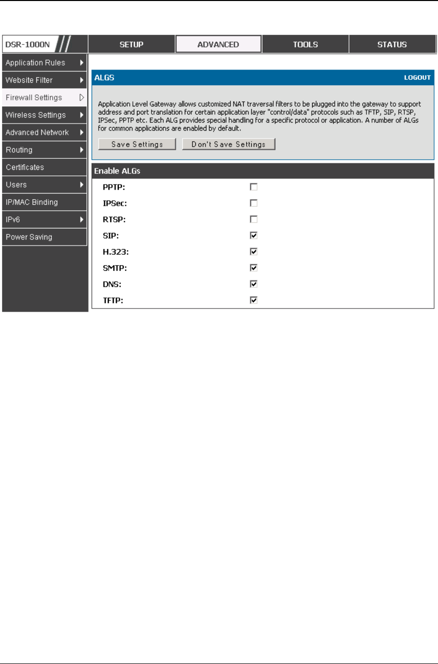
Unified Services Router User Manual
100
Figure 61: Availa ble ALG support on the router .
5.7 VPN Passthrough for Firewall
Advanced > Firewall Settings > VPN Passthrough
This router’s firewall settings can be configured to allow encrypted VPN traffic for
IPsec, PPTP, and L2TP VPN tunnel connections between the LAN and internet. A
specific firewall rule or service is not appropriate to introduce this passthrough
support; instead the appropriate check boxes in the VPN Passthrough page must be
enabled.
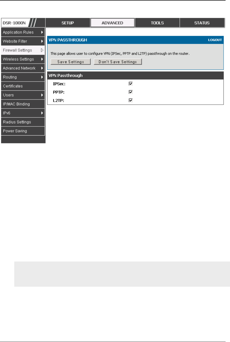
Unified Services Router User Manual
101
Figure 62: Passthrough options for VPN tunnels
5.8 Application Rules
Advanced > Application Rules > Application Rules
Application rules are also referred to as port triggering. This feature allows devices
on the LAN or DMZ to request one or mo re ports to be forwarded to them. Port
triggering waits for an outbound request from the LAN/DMZ on one of the defined
outgoing ports, and then opens an incoming port for that specified type of traffic. This
can be thought of as a form of dynamic port forwarding while an application is
transmitting data over the opened outgoing or incoming port(s).
Port triggering application rules are more flexible than static port forwarding that is
an available option when configuring firewall rules. This is because a port triggering
rule does not have to reference a specific LAN IP or IP range. As well ports are not
left open when not in use, thereby providing a level of security that port forwarding
does not offer.
Port triggering is not appropriate for servers on the LAN, since there is a
dependency on the LAN device making an outgoing connection before incoming
ports are opened.
Some applications require that when external devices connect to them, they receive
data on a specific port or range of ports in order to fu nction properly. The router must
send all incoming data for that application only on the required port or range of ports.
The router has a list of common applications and games with corresponding outbound
and inbound ports to open. You can also specify a port triggering rule by defining the
type of traffic (TCP or UDP) and the range of incoming and outgoing ports to open
when enabled.
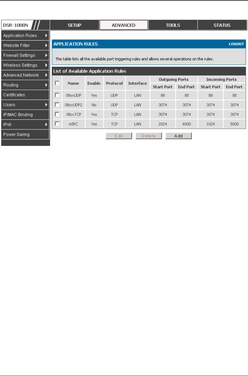
Unified Services Router User Manual
102
Figure 63: Li st of Available Applica tion Rules showing 4 unique rules
The application rule status page will list any active rules, i.e. incoming ports that are
being triggered based on outbound requests from a defined outgoing port.
5.9 Web Content Filtering
The gateway offers some standard web filtering options to allow the admin to easily
create internet access policies between the secure LAN and insecure WAN. Instead of
creating policies based on the type of traffic (as is the case when using firewall rules),
web based content itself can be used to determine if traffic is allowed or dropped.
5.9.1 Content Filtering
Advanced > Website Filter > Content Filtering
Content filtering must be enabled to configure and use the subsequent features (list of
Trusted Domains, filtering on Blocked Keywords, etc.). Proxy servers, which can be
used to circumvent certain firewall rules and thus a potential security gap, can be
blocked for all LAN devices. Java applets can be prevented from being downloaded
from internet sites, and similarly the gateway can prevent ActiveX controls from
being downloaded via Internet Explorer. For added security cookies, which typically
contain session information, can be blocked as well for all devices on the private
network.
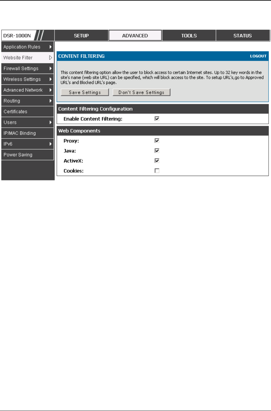
Unified Services Router User Manual
103
Figure 64: Content Filtering used to bl ock access to proxy servers and
prevent ActiveX co ntrols from being downloaded
5.9.2 Approved URLs
Advanced > Website Filter > Approved URLs
The Approved URLs is an acceptance list for all URL domain names. Domains added
to this list are allowed in any form. For example, if the domain “yahoo” is added to
this list then all of the following URL’s are permitted access from the LAN:
www.yahoo.com, yahoo.co.uk, etc. Import/export from a text or CSV file for
Approved URLs is also supported
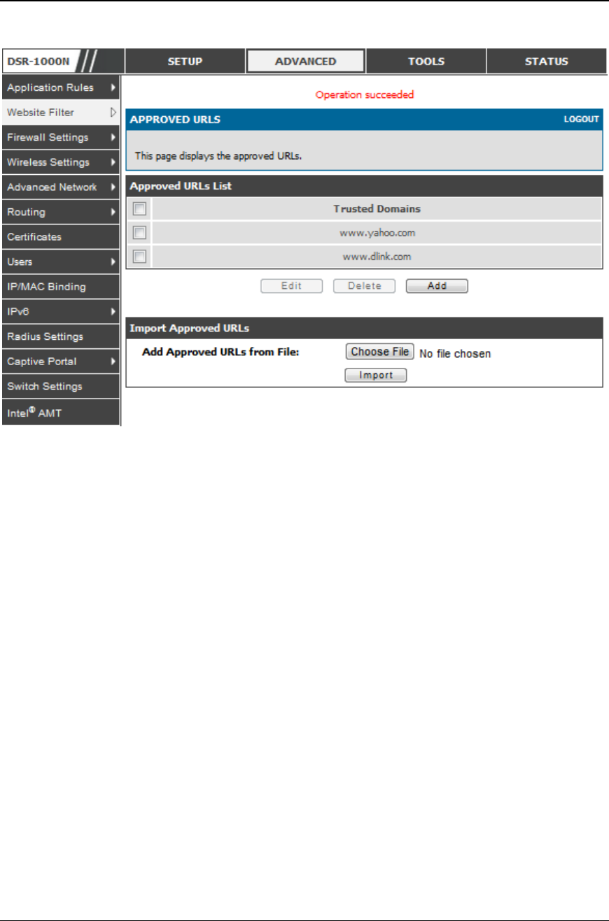
Unified Services Router User Manual
104
Figure 65: Two tr ust ed domains adde d to the Approved U RLs List
5.9.3 Blocked Keywords
Advanced > Website Filter > Blocked Keywords
Keyword blocking allows you to block all website URL’s or site content that contains
the keywords in the configured list. This is lower priority than the Approved URL
List; i.e. if the blocked keyword is present in a site allowed by a Trusted Domain in
the Approved URL List, then access to that site will be allowed. Import/export from a
text or CSV file for keyword blocking is also supported.
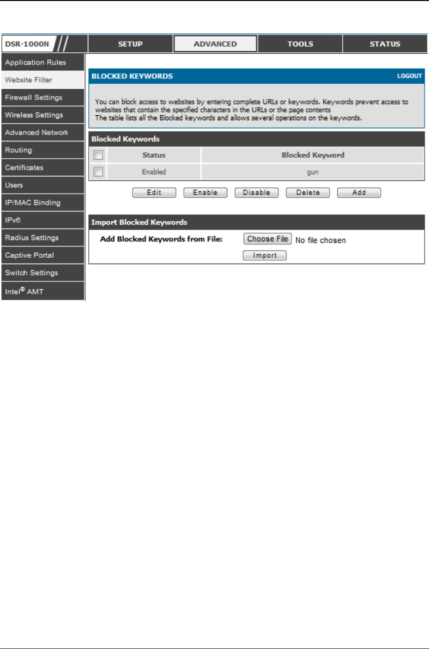
Unified Services Router User Manual
105
Figure 66: One keyword added to t he bloc k list
5.9.4 Export Web Filter
Advanced > Website Filter > Export
Export Approved URLs: Feature enables the user to export the URLs to be allowed to
a csv file which can then be downloaded to the local host. The user has to click the
export button to get the csv file.
Export Blocked Keywords: This feature enables the user to export the keywords to be
blocked to a csv file which can then be downloaded to the local host. The user has to
click the export button to get the csv file .
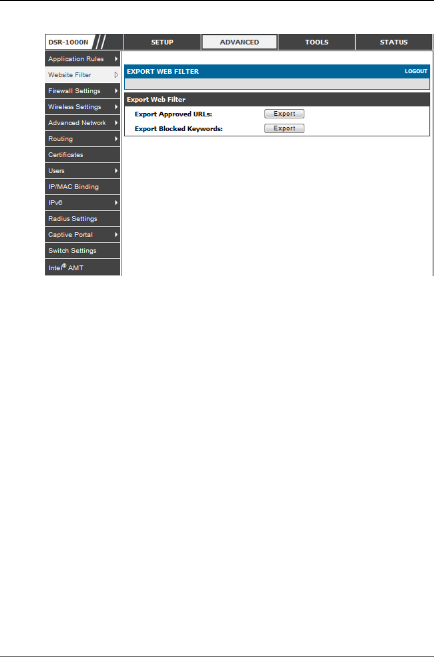
Unified Services Router User Manual
106
Figure 67: Ex port Approved URL list
5.10 IP/MAC Binding
Advanced > IP/MAC Binding
Another available security measure is to only allow outbound traffic (from the LAN to
WAN) when the LAN node has an IP address matching the MAC address bound to it.
This is IP/MAC Binding, and by enforcing the gateway to validate the source traffic’s
IP address with the unique MAC Address of the configured LAN node, the
administrator can ensure traffic from that IP address is not spoofed. In the event of a
violation (i.e. the traffic’s source IP address doesn’t match up with the expected MAC
address having the same IP address) the packets will be dropped and can be logged for
diagnosis.
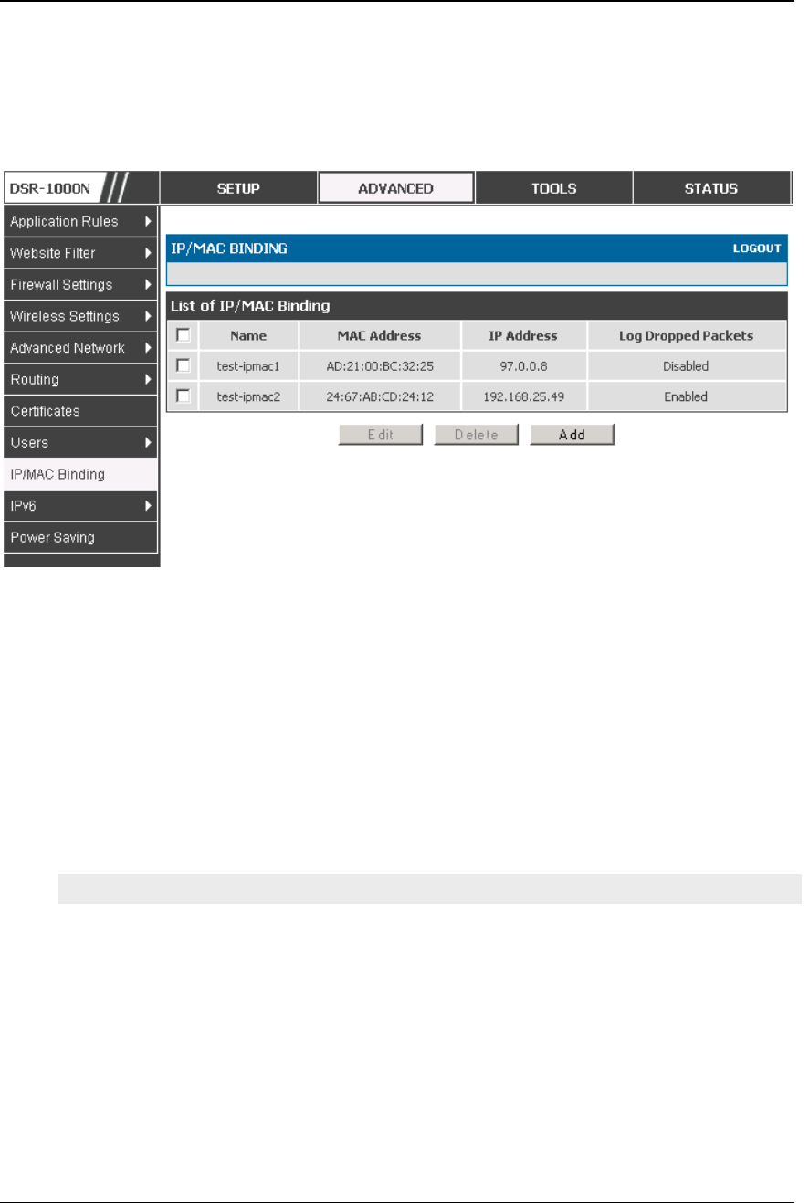
Unified Services Router User Manual
107
Figure 68: The following example binds a L A N ho st’ s MAC Address to an
IP address served by DSR. If there is an IP/MAC Binding
violation, the violati ng packet will be dr opped and logs will be
captured
5.11 Intrusion Prevention (IPS)
Advanced > Advanced Network > IPS
The gateway’s Intrusion Prevention System (I PS) prevents malicious attacks from the
internet from accessing the private network. Static attack signatures loaded to the
DSR allow common attacks to be detected and prevented. The checks can be enabled
between the WAN and DMZ or LAN, and a running counter will allow the
administrator to see how many malicious intrusion attempts from the WAN have been
detected and prevented.
DSR-150/150N does not support Intrusion Prevention S ystem.
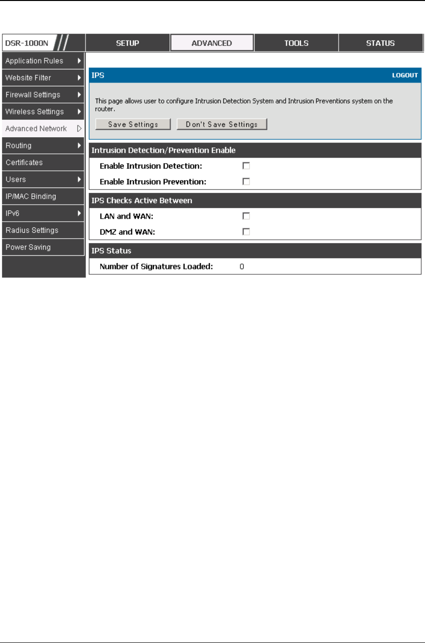
Unified Services Router User Manual
108
Figure 69: Intr usi on Prevention f eatures on the router
5.12 Protecting from Internet Attacks
Advanced > Advanced Network > Attack Checks
Attacks can be malicious security breaches or unintentional network issues that
render the router unusable. Attack checks allow you to manage WAN security
threats such as continual ping requests and discovery via ARP scans. TCP and UDP
flood attack checks can be enabled to manage extreme usage of WAN resources.
Additionally certain Denial-of-Service (DoS) attacks can be blocked. These attacks,
if uninhibited, can use up processing power and bandwidth and prevent regular
network services from running normally. ICMP packet flooding, SYN traffic
flooding, and Echo storm thresholds can be configured to temporarily suspect traffic
from the offending source.
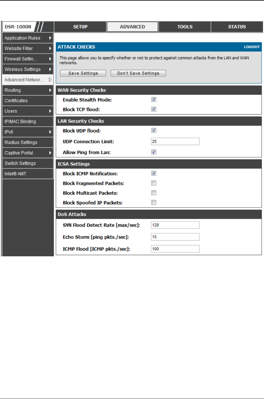
Unified Services Router User Manual
109
Figure 70: Protecting the router and LAN f rom internet attacks
WAN Security Checks:
Enable Stealth Mode: If Stealth Mode is enabled, the router will not respond to port
scans from the WAN. This makes it less susceptible to discovery and attacks.
Block TCP Flood: If this option is enabled, the router will drop all invalid TCP
packets and be protected from a SYN flood attack.
LAN Security Checks:
Block UDP Flood: If this option is enabled, the router will not accept more than 20
simultaneous, active UDP connections from a single computer on the LAN.
UDP Connection Limit: You can set the number of simultaneous active UDP
connections to be accepted from a single computer on the LAN; the default is 25
ICSA Settings:
Block ICMP Notification: selecting t his prevents ICMP packets from being
identified as such. ICMP packets, if identified, can be captured and used in a Ping
(ICMP) flood DoS attack.

Unified Services Router User Manual
110
Block Fragmented Packets: selecting this option drops any fragmented packets
through or to the gateway
Block Multicast Packets: selecting this option drops multicast packets, which could
indicate a spoof attack, through or to the gateway.
DoS Attacks:
SYN Flood Detect Rate (max/sec): The rate at which the SYN Flood can be
detected.
Echo Storm (ping pkts/sec): The number of ping packets per second at which the
router detects an Echo storm attack from the WAN and prevents further ping traffic
from that external address.
ICMP Flood (ICMP pkts/sec): The number of ICMP packets per second at which the
router detects an ICMP flood attack from the WAN and prevents further ICMP
traffic from that external address.
The ping on LAN interfaces is enabled in default. To disable the ping response
from LAN hosts to the LAN/WAN port of the device uncheck the "Allow Ping from
LAN"option.
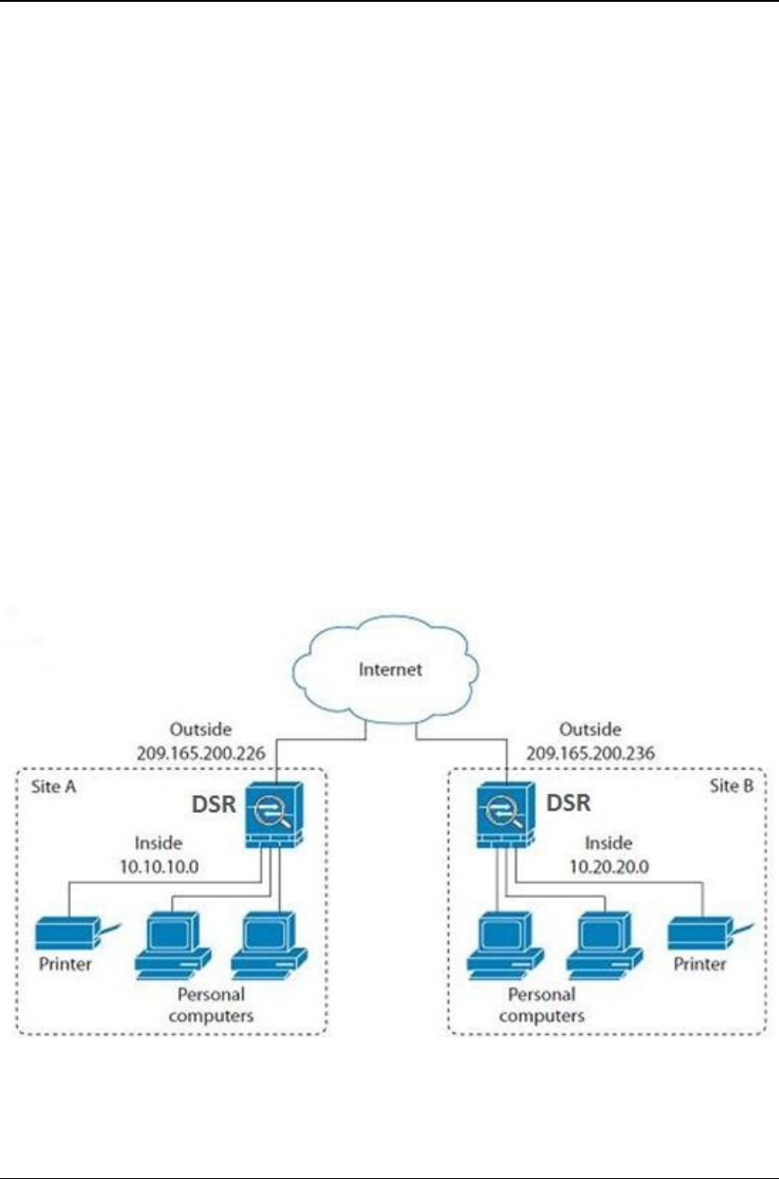
Unified Services Router User Manual
111
Chapter 6. IPsec / PPTP / L2TP VPN
A VPN provides a secure communication channel (“tunnel”) between two gateway
routers or a remote PC client. The following types of tunnels can be created:
Gateway-to-gateway VPN: to connect two or more routers to secure traffic between
remote sites.
Remote Client (client-to-gateway VPN tunnel): A remote client initiates a VPN
tunnel as the IP address of the remote PC client is not known in advance. The
gateway in this case acts as a responder.
Remote client behind a NAT router: The client has a dynamic IP address and is
behind a NAT Router. The remote PC client at the NAT router initia tes a VPN
tunnel as the IP address of the remote NAT router is not known in advance. T he
gateway WAN port acts as responder.
PPTP server for LAN / WAN PPTP client connections.
L2TP server for LAN / WAN L2TP client connections.
Figure 71: Ex ample of Gateway -to-Gateway IPsec VPN t unnel using two
DSR routers connect ed to the Internet
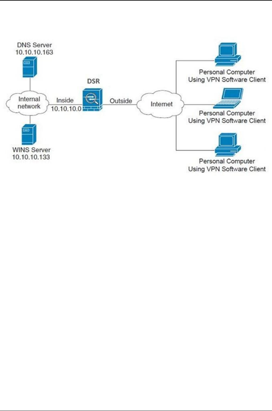
Unified Services Router User Manual
112
Figure 72: Example of three IPsec client connections to the internal
networ k through t he DSR IPsec gateway
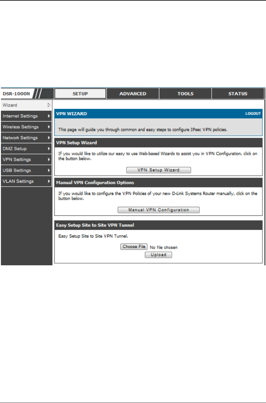
Unified Services Router User Manual
113
6.1 VPN Wizard
Setup > Wizard > VPN Wizard
You can use the VPN wizard to quickly create both IKE and VPN policies. Once the
IKE or VPN policy is created, you can modify it as required.
Figure 73: VPN Wizard launch screen
To easily establish a VPN tunnel using VPN Wizard, follow the steps below:
1. Select the VPN tunnel type to create
The tunnel can either be a gateway to gateway connecti on (site-to-site) or a tunnel
to a host on the internet (remote access).
Set the Connection Name and pre-shared key: the connection name is used for
management, and the pre-shared key will be required on the VPN client or gateway
to establish the tunnel
Determine the local gateway for this tunnel; if there is more than 1 WAN
configured the tunnel can be configured for either of the gateways.
Unified Services Router User Manual
114
2. Configure Remote and Local WAN address for the tunnel endpoints
Remote Gateway Type: identify the remote endpoint of the tunnel by FQDN or
static IP address
Remote WAN IP address / FQDN: This field is enabled only if the peer you are
trying to connect to is a Gateway. For VPN Clients, this IP address or Internet
Name is determined when a connection request is received from a client.
Local Gateway Type: identify this router’s endpoint of the tunnel by FQDN or
static IP address
Local WAN IP address / FQDN: This field can be left blank if you are not using a
different FQDN or IP address than the one specified in the WAN p ort’s
configuration.
3. Configure the Secure Connection Remote Accessibility fields to identify the remote
network:
Remote LAN IP address: address of the LAN behind the peer gateway
Remote LAN Subnet Mask: the subnet mask of the LAN behind the peer
Note: The IP address range used on the remote LAN must be different from the IP
address range used on the local LAN.
4. Review the settings and click Connect to establish the tunnel.
The Wizard will create an Auto IPsec policy with the following default values for a
VPN Client or Gateway policy (these can be accessed from a link on the Wizard
page):
Parameter
Default value from Wizard
Exchange Mode
Aggressive (Client policy ) or Main (Gateway policy)
ID Type
FQDN
Local WAN ID
wan_local.com (only applies to Client policies)
Remote WAN ID
wan_remote.com (only applies to Client policies)
Encryption Algorithm
3DES
Authentication Algorithm
SHA-1
Authentication Method
Pre-shared Key
PFS Key-Group
DH-Group 2(1024 bit)
Life Time (Phase 1)
24 hours
Life Time (Phase 2)
8 hours

Unified Services Router User Manual
115
Parameter
Default value from Wizard
Exchange Mode
Aggressive (Client policy ) or Main (Gateway policy)
ID Type
FQDN
Local WAN ID
wan_local.com (only applies to Client policies)
Remote WAN ID
wan_remote.com (only applies to Client policies)
Encryption Algorithm
3DES
Authentication Algorithm
SHA-1
Authentication Method
Pre-shared Key
PFS Key-Group
DH-Group 2(1024 bit)
Life Time (Phase 1)
24 hours
NETBIOS
Enabled (only applies to Gateway policies)
The VPN Wizard is the recommended method to set up an Auto IPsec policy.
Once the Wizard creates the matching IKE and VPN policies required by the Auto
policy, one can modify the required fields through the edit link. Refer to the online
help for details.
Easy Setup Site to Site VPN Tunnel:
If you find it difficult to configure VPN policies through VPN wizard use easy setup
site to site VPN tunnel. This will add VPN policies by importing a file containing vpn
policies.
6.2 Configuring IPsec Policies
Setup > VPN Settings > IPsec > IPsec Policies
An IPsec policy is between this router and another gateway or this router and a IPsec
client on a remote host. The IPsec mode can be either tunnel or transport depending
on the network being traversed between the two policy endpoints.
Transport: This is used for end-to-end communication between this router and the
tunnel endpoint, either another IPsec gateway or an IPsec VPN client on a host.
Only the data payload is encrypted and the IP header is not modified or encrypted.
Tunnel: This mode is used for network-to-network IPsec tunnels where this
gateway is one endpoint of the tunnel. In this mode the entire IP packet including
the header is encrypted and/or authenticated.
When tunnel mode is selected, you can enable NetBIOS and DHCP over IPsec.
DHCP over IPsec allows this router to serve IP leases to hosts on the remote LAN. As
well in this mode you can define the single IP address, range of IPs, or s ubnet on both
the local and remote private networks that can communicate over the tunnel.
Unified Services Router User Manual
116
Figure 74: IPsec policy configuratio n
Once the tunnel type and endpoints of the tunnel are defined you can determine the
Phase 1 / Phase 2 negotiation to use for the tunnel. This is covered in the IPsec mode
setting, as the policy can be Manual or Auto. For Auto policies, the Internet Key
Exchange (IKE) protocol dynamically exchanges keys between two IPsec hosts. The
Phase 1 IKE parameters are used to define the tunnel’s security association details.
The Phase 2 Auto policy parameters cover the security association lifetime and
encryption/authentication details of the phase 2 key negotiation.
Unified Services Router User Manual
117
The VPN policy is one half of the IKE/VPN policy pair required to establish an Auto
IPsec VPN tunnel. The IP addresses of the machine or machines on the two VPN
endpoints are configured here, along with the policy parameters required to secure the
tunnel
Figure 75: IPsec policy configuratio n continue d (Auto policy via IKE)
A Manual policy does not use IKE and instead relies on manual keying to exchange
authentication parameters between the two IPsec hosts. The incoming and outgoing
security parameter index (SPI) values must be mirrored on the remote tunnel

Unified Services Router User Manual
118
endpoint. As well the encryption and integrity algorithms and keys must match on the
remote IPsec host exactly in order for the tunnel to establish successfully. Note that
using Auto policies with IKE are preferred as in some IPsec implementations the SPI
(security parameter index) values require conversion at each endpoint.
DSR supports VPN roll-over feature. This means that policies configured on primary
WAN will rollover to the secondary WAN in case of a link failure on a primary
WAN. This feature can be used only if your WAN is configured in Auto-Rollover
mode.
Unified Services Router User Manual
119
Figure 76: IPsec policy configuratio n continued (Auto / Manual Phase 2)
6.2.1 Extended Authentication (XAUTH)
You can also configure extended authentication (XAUTH). Rather than configure a
unique VPN policy for each user, you can configure the VPN gateway router to
authenticate users from a stored list of user accounts or with an external
authentication server such as a RADIUS server. With a user database, user accounts
created in the router are used to authenticate users.

Unified Services Router User Manual
120
With a configured RADIUS server, the router connects to a RADIUS server and
passes to it the credentials that it receives from the VPN client. You can secure the
connection between the router and the RADIUS server with the authentication
protocol supported by the server (PAP or CHAP). For RADIUS – PAP, the router
first checks in the user database to see if the user credentials are available; if they
are not, the router connects to the RADIUS server.
6.2.2 Internet over IPSec tunnel
In this feature all the traffic will pass through the VPN Tunnel and from the Remote
Gateway the packet will be routed to Internet. On the remote gateway side, the
outgoing packet will be SNAT'ed.
6.3 Configuring VPN clients
Remote VPN clients must be configured with the same VPN policy parameters used in
the VPN tunnel that the client wishes to use: encryption, authentication, life time, and
PFS key-group. Upon establishing these authentication parameters, the VPN Client
user database must also be populated with an account to give a user access to the
tunnel.
VPN client software is required to establish a VPN tunnel between the router and
remote endpoint. Open source software (such as OpenVPN or Ope nswan) as well as
Microsoft IPsec VPN software can be configured with the required IKE policy
parameters to establish an IPsec VPN tunnel. Refer to the client software guide for
detailed instructions on setup as well as the router’s online help.
The user database contains the list of VPN user accounts that are authorized to use a
given VPN tunnel. Alternatively VPN tunnel users can be authenticated using a
configured Radius database. Refer to the online help to determine how to populate the
user database and/or configure RADIUS authentication.
6.4 PPTP / L2TP Tunnels
This router supports VPN tunnels from either PPTP or L2TP ISP servers. The router
acts as a broker device to allow the ISP's server to create a TCP control connection
between the LAN VPN client and the VPN server.
6.4.1 PPTP Tunnel Support
Setup > VPN Settings > PPTP > PPTP Client
PPTP VPN Client can be configured on this router. Using this client we can access
remote network which is local to PPTP server. Once client is enabled, the user can
access Status > Active VPNs page and establish PPTP VPN tunnel clicking
Connect. To disconnect the tunnel, click Drop.
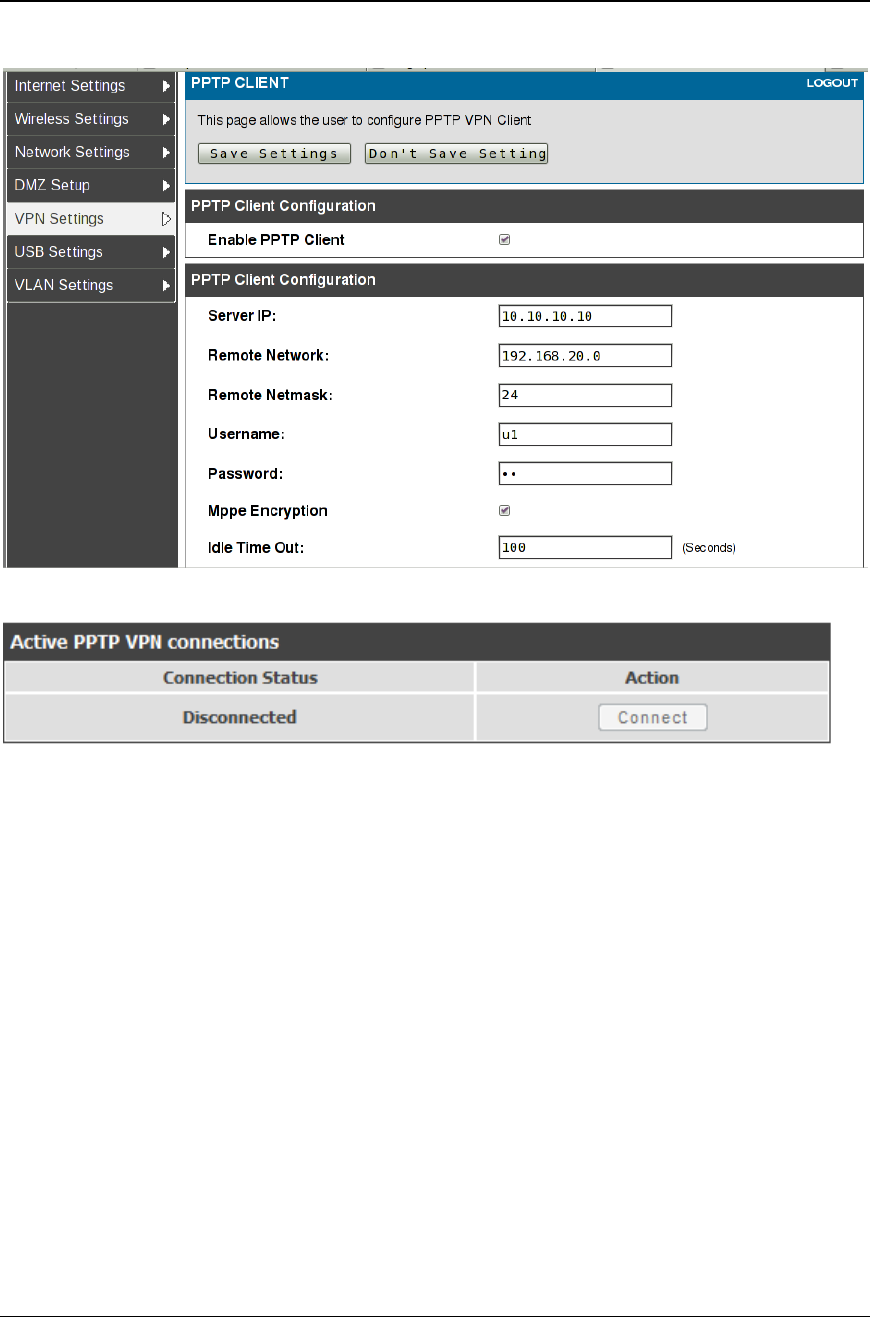
Unified Services Router User Manual
121
Figure 77: PPTP tunnel configuratio n – PPTP Client
Figure 78: PPTP VPN connection status
Setup > VPN Settings > PPTP > PPTP Server
A PPTP VPN can be established through this router. Once enabled a PPTP server is
available on the router for LAN and WAN PPTP client users to access. Once the
PPTP server is enabled, PPTP clients that are within t he range of configured IP
addresses of allowed clients can reach the router’s PPTP server. Once authenticated
by the PPTP server (the tunnel endpoint), PPTP clients have access to the network
managed by the router.
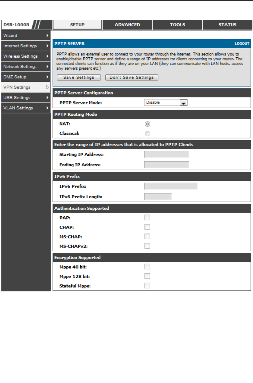
Unified Services Router User Manual
122
Figure 79: PPTP tunnel co nf iguration – PPTP Server
6.4.2 L2TP Tunnel Support
Setup > VPN Settings > L2TP > L2TP Server
A L2TP VPN can be established through this router. Once enabled a L2TP server is
available on the router for LAN and WAN L2TP client users to access. Once t he
L2TP server is enabled, L2TP clients that are within the range of configured IP
addresses of allowed clients can reach the router’s L2TP server. Once authenticated
by the L2TP server (the tunnel endpoint), L2TP clients have access to the network
managed by the router.
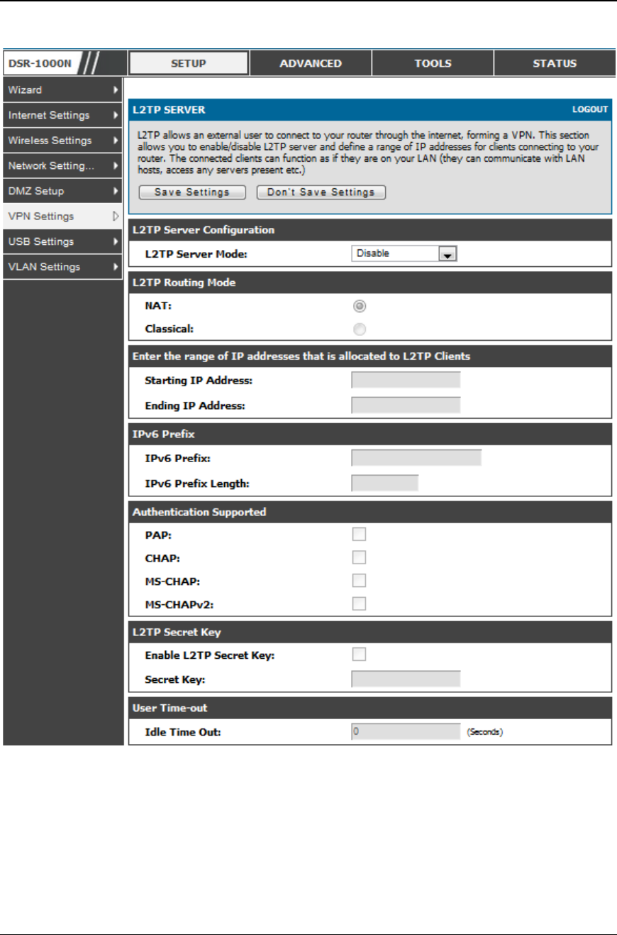
Unified Services Router User Manual
123
Figure 80: L2 TP tunnel configuration – L2TP Server
6.4.3 OpenVPN Support
Setup > VPN Settings > OpenVPN > OpenVPN Configuration
OpenVPN allows peers to authenticate each other using a pre -shared secret key,
certificates, or username/password. When used in a multiclient -server configuration,
it allows the server to release an authentication certificate for every client, using

Unified Services Router User Manual
124
signature and Certificate authority. An Open VPN can be established through this
router. Check/Uncheck this and click save settings to start/stop openvpn server.
Mode: OpenVPN daemon mode. It can run in server mode, client mode or
access server client mode. In access server client mode, the user has to
download the auto login profile from the Openvpn Access Server and upload
the same to connect.
Server IP: OpenVPN server IP address to which the client
connects(Applicable in client mode).
Vpn Network: Address of the Virtual Network.
Vpn Netmask: Netmask of the Virtual Network.
Port: The port number on which openvpn server(or Access Server) runs.
Tunnel Protocol: The protocol used to communicate with the remote host.
Ex: Tcp, Udp. Udp is the default.
Encryption Algorithm: The cipher with which the packets are encrypted. Ex:
BF-CBC, AES-128,AES-192 and AES-256. BF-CBC is the default
Hash algorithm: Message digest algorithm used to authenticate packets. Ex:
SHA1, SHA256 and SHA512. SHA1 is the default.
Tunnel Type: Select Full Tunnel to redirect all the traffic through the
tunnel. Select Split Tunnel to redirect traffic to only specified resources
(added from openVpnClient Routes) through the tunnel. Full Tunnel is the
default.
Enable Client to Client communication: Enable this to allow openvpn clients
to communicate with each other in split tunnel case. Disabled by default.
Upload Access Server Client Configuration: The user has to download the
auto login profile and upload here to connect this router to the OpenVPN
Access Server.
Certificates: Select the set of certificates openvpn server uses. First Row:
Set of certificates and keys the server uses. Second Row: Set of certificates
and keys newly uploaded.
Enable Tls Authentication Key: Enabling this adds Tls authentication which
adds an additional layer of authentication. Can be checked only when the tls
key is uploaded. Disabled by default.
Click Save Settings to save the settings.
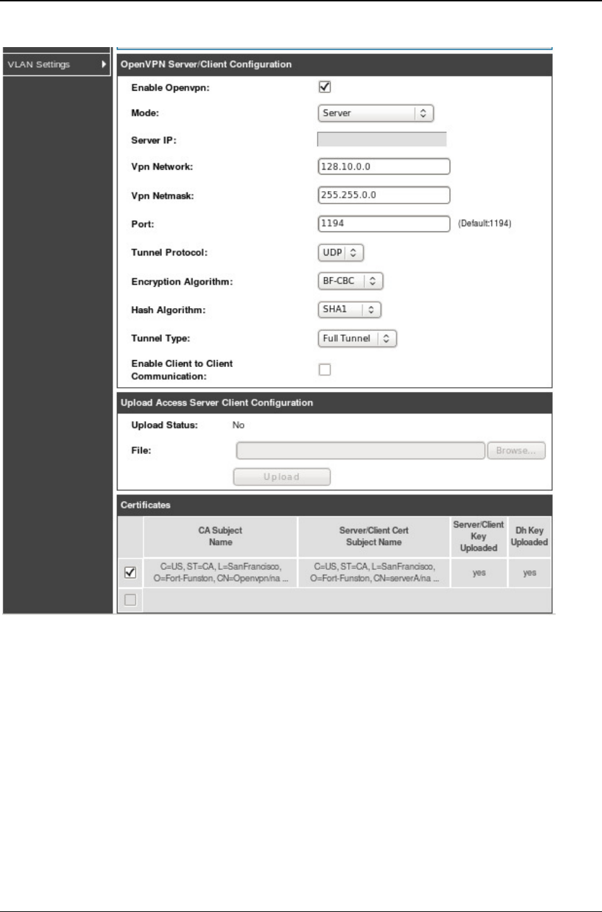
Unified Services Router User Manual
125
Figure 81: Ope nVPN configuration
6.4.4 OpenVPN Remote Network
Setup > VPN Settings > OpenVPN > OpenVPN Remote Network (Site-to-
Site)
This page allows the user to add/edit a remote network and netmask which allows the
other OpenVPN clients to reach this network.
Unified Services Router User Manual
126
Figure 82: Ope nVPN Remote Networ k
Common Name: Common Name of the OpenVPN client certificate.
Remote Network: Network address of the remote resource.
Subnet Mask: Netmask of the remote resource.
6.4.5 OpenVPN Authentication
Setup > VPN Settings > OpenVPN > OpenVPN Authentication
This page allows the user to upload required certificates and keys.
Unified Services Router User Manual
127
Figure 83: OpenVPN Authentication
Trusted Certificate (CA Certificate): Browse and upload the pem formatted CA
Certificate.
Server/Client Certificate: Browse and upload the pem formatted Server/Client
Certificate.
Server/Client Key: Browse and upload the pem formatted Server/Client Key.
DH Key: Browse and upload the pem formatted Diffie Hellman Key.
Tls Authentication Key: Browse and upload the pem formatted Tls Authentication
Key.

Chapter 7. SSL VPN
The router provides an intrinsic SSL VPN feature as an alternate to the standard IPsec
VPN. SSL VPN differs from IPsec VPN mainly by removing the requirement of a pre -
installed VPN client on the remote host. Instead, users can securely login through the
SSL User Portal using a standard web browser and receive access to configure d
network resources within the corporate LAN. The router supports multiple concurrent
sessions to allow remote users to access the LAN over an encrypted link through a
customizable user portal interface, and each SSL VPN user can be assigned unique
privileges and network resource access levels.
The remote user can be provided different options for SSL service through this router:
VPN Tunnel: The remote user’s SSL enabled browser is used in place of a VPN
client on the remote host to establish a secure VPN tunnel. A SSL VPN client
(Active-X or Java based) is installed in the remote host to allow the client to join
the corporate LAN with pre-configured access/policy privileges. At this point a
virtual network interface is created on the user’s host and this will be assigned an
IP address and DNS server address from the router. Once established, the host
machine can access allocated network resources.
Port Forwarding: A web-based (ActiveX or Java) client is installed on the client
machine again. Note that Port Forwarding service only supports TCP connections
between the remote user and the router. The router administrator can define specific
services or applications that are available to remote port forwarding users instead
of access to the full LAN like the VPN tunnel.
ActiveX clients are used when the remote user accesses the portal using the Internet
Explorer browser. The Java client is used for other browsers like Mozilla Firefox,
Netscape Navigator, Google Chrome, and Apple Safari.
Unified Services Router User Manual
130
Figure 84: Ex ample of clientless SSL VPN connections t o the DSR
Unified Services Router User Manual
131
7.1 Groups and Users
Advanced > Users > Groups
The group page allows creating, editing and deleting groups. The groups are
associated to set of user types. The lists of available groups are displayed in the “List
of Group” page with Group name and description of group.
Click Add to create a group.
Click Edit to update an existing group.
Click Delete to clear an existing group.
Figure 85: Li st of groups
Group configuration page allows to create a group with a different type of users. The
user types are as follows:
PPTP User: These are PPTP VPN tunnel LAN users that can establish a tunnel
with the PPTP server on the WAN.
L2TP User: These are L2TP VPN tunnel LAN users that can establish a tunnel
with the L2TP server on the WAN.
Xauth User: This user’s authentication is performed by an externally
configured RADIUS or other Enterprise server. It is not part of the local user
database.
SSLVPN User: This user has access to the SSL VPN services as determined
by the group policies and authentication domain of which it is a member. The
domain-determined SSL VPN portal will be displayed when logging in with
this user type.
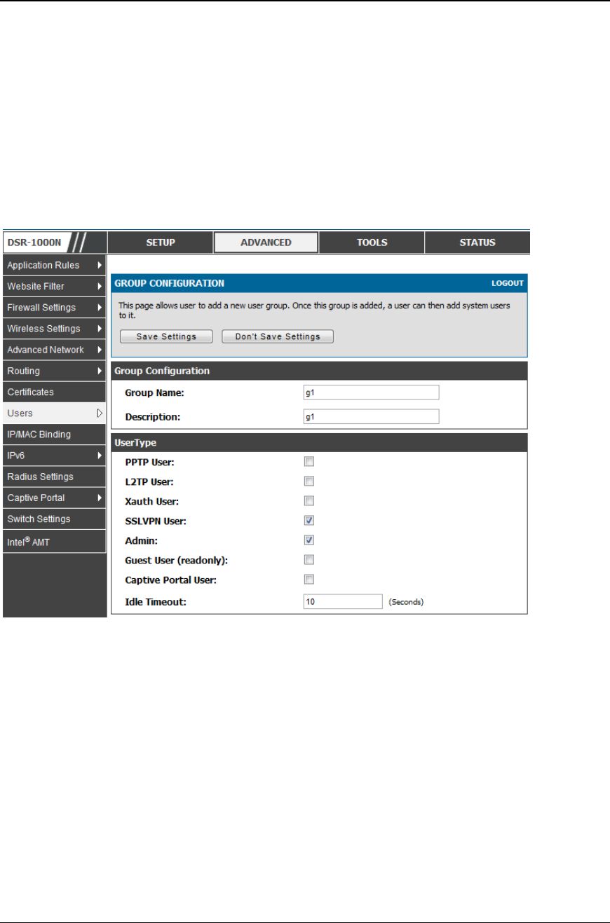
Unified Services Router User Manual
132
Admin: This is the router’s super-user, and can manage the router, use SSL
VPN to access network resources, and login to L2TP/PPTP servers on the
WAN. There will always be one default administrator user for the GUI
Guest User (read-only): The guest user gains read only access to the GUI to
observe and review configuration settings. The guest does not have SSL VPN
access.
Captive Portal User: These captive portal users has access through the router.
The access is determined based on captive portal policies.
Idle Timeout: This the log in timeout period for users of this group.
Figure 86: User group configuration
When SSLVPN users are selected, the SSLVPN settings are displayed with the
following parameters as captured in SSLVPN Settings. As per the Authentication
Type SSL VPN details are configured.
Authentication Type: The authentication Type can be one of the following:
Local User Database (default), Radius -PAP, Radius-CHAP, Radius-MSCHAP,
Radius-MSCHAPv2, NT Domain, Active Directory and LDAP.
Authentication Secret: If the domain uses RADIUS authentication then the
authentication secret is required (and this has to match the secret configured
on the RADIUS server).
Workgroup: This is required is for NT domain authentication. If there are
multiple workgroups, user can enter the details for up to two workgroups.
LDAP Base DN: This is the base domain name for the LDAP authentication
server. If there are multiple LDAP authentication servers, user can enter the
details for up to two LDAP Base DN.
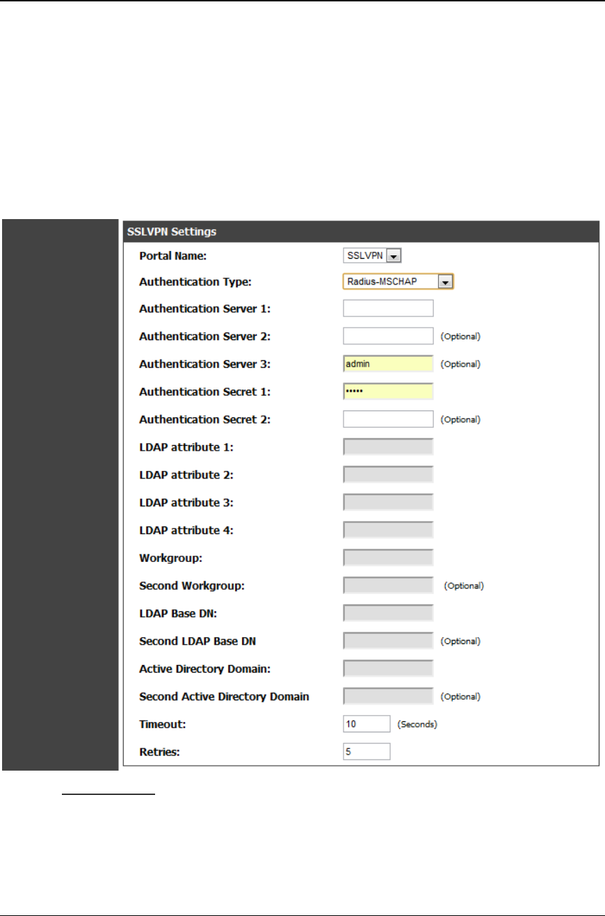
Unified Services Router User Manual
133
Active Directory Domain: If the domain uses the Active Directory
authentication, the Active Directory domain name is required. Users
configured in the Active Directory database are given access to the SSL VPN
portal with their Active Directory username and password. If there are
multiple Active Directory domains, user can enter the details for up to two
authentication domains.
Timeout: The timeout period for reaching the authentication server.
Retries: The number of retries to authenticate with the authentication server
after which the DSR stops trying to reach the server.
Figure 87: SSLVPN Settings
Login Policies
To set login policies for the group, s elect the corresponding group click “Login
policies”. The following parameters are configured:
Group Name: This is the name of the group that can have its login policy
edited
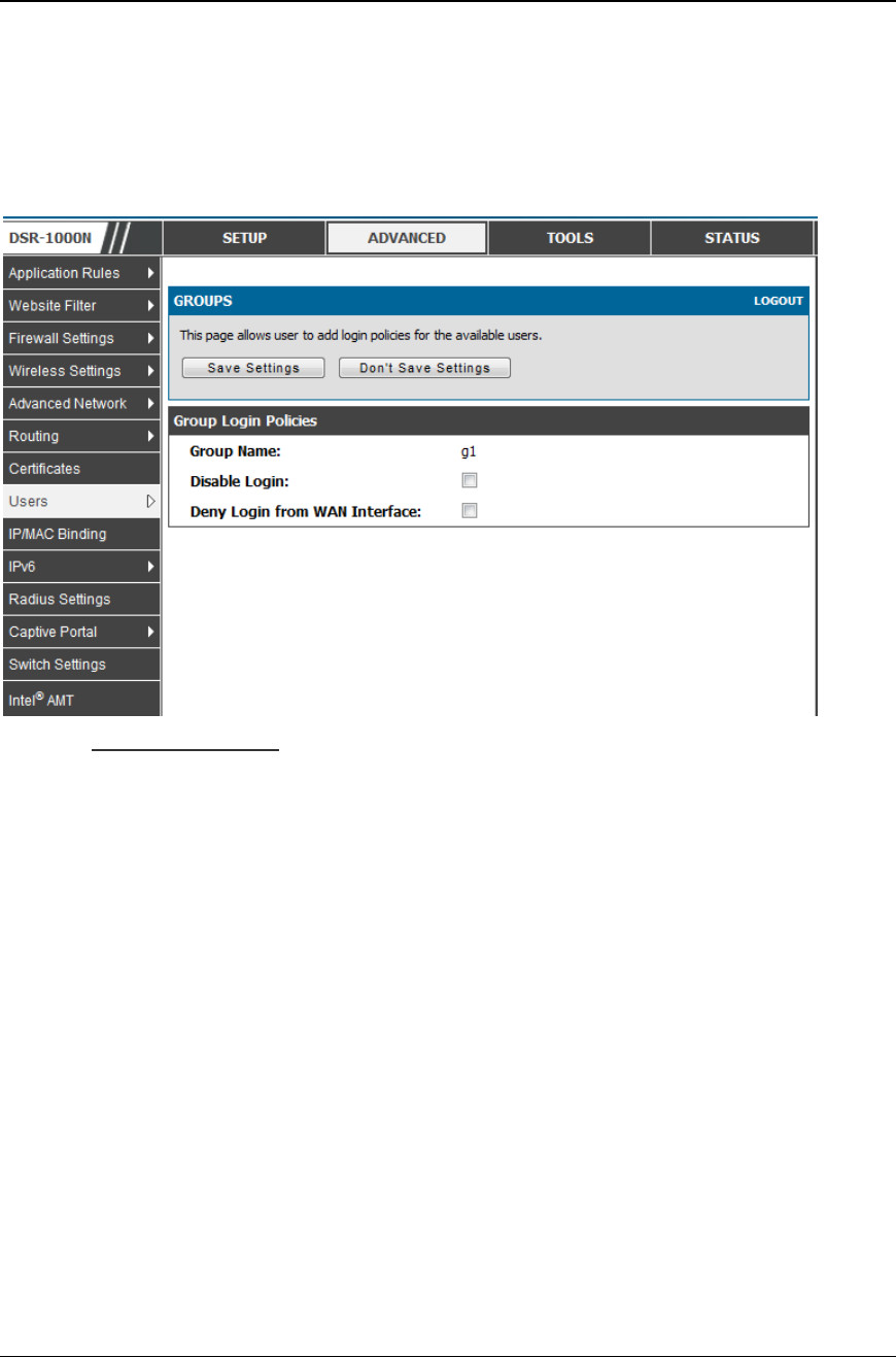
Unified Services Router User Manual
134
Disable Login: Enable to prevent the users of this group from logging into the
devices management interface(s)
Deny Login from WAN interface: Enable to prevent the users of this group
from logging in from a WAN (wide area network) interface. In this case only
login through LAN is allowed.
Figure 88: Group lo gin policies options
Policy by Browsers
To set browser policies for the group, select the corresponding group click “ Policy by
Browsers”. The following parameters are configured:
Group Name: This is the name of the group that can have its login policy
edited
Deny Login from Defined Browsers: The list of defined browsers below will
be used to prevent the users of this group from logging in to the routers GUI.
All non-defined browsers will be allowed for login for this group.
Allow Login from Defined Browsers: The list of defined browsers below will
be used to allow the users of this group from logging in to the routers GUI.
All non-defined browsers will be denied for login for this group.
Defined Browsers:This list displays the web browsers that have been added to
the Defined Browsers list, upon which group login policies can be defined.
(Check Box At First Column Header): Selects all the defined browsers in the
table.
Delete: Deletes the selected browser(s).
You can add to the list of Defined Browsers by selecting a client browser from the
drop down menu and clicking Add. This browser will then appear in the above list
of Defined Browsers.
Click Save Settings to save your changes.
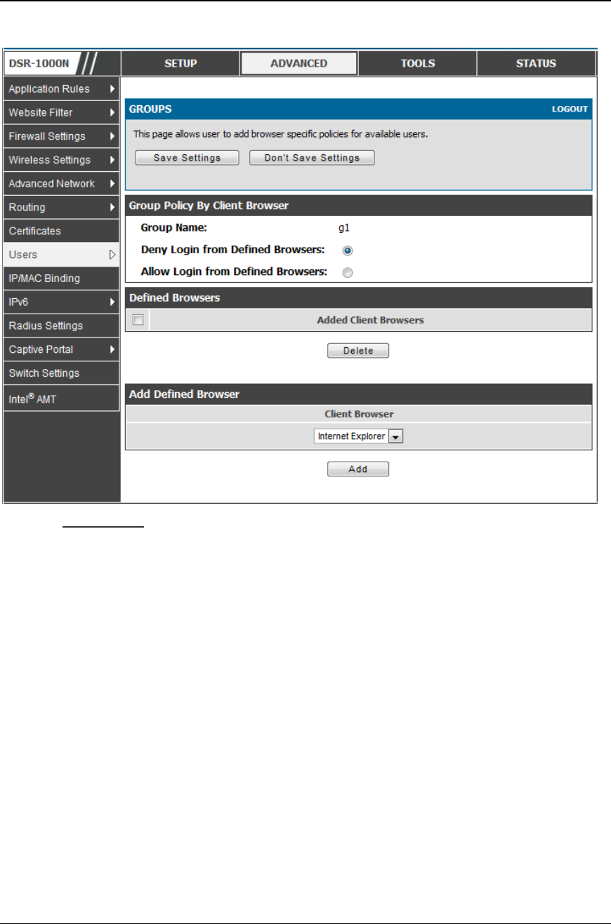
Unified Services Router User Manual
135
Figure 89: Browser policies options
Policy by IP
To set policies bye IP for the group, select the corresponding group click “Policy by
IP”. The following parameters are configured:
Group Name: This is the name of the group that can have its login policy
edited
Deny Login from Defined Browsers: The list of defined browsers below will
be used to prevent the users of this group from logging in to the routers GUI.
All non-defined browsers will be allowed for login for this group.
Allow Login from Defined Browsers: The list of defined browsers below will
be used to allow the users of this group from logging in to the routers GUI.
All non-defined browsers will be denied for login for this group.
Defined Browsers:This list displays the web browsers that have been added to
the Defined Browsers list, upon which group login policies can be defined.
(Check Box At First Column Header): Selects all the defined browsers in the
table.
Delete: Deletes the selected browser(s).
You can add to the list of Defined Browsers by selecting a client browser from the
drop down menu and clicking Add. This browser will then appear in the above list
of Defined Browsers.
Unified Services Router User Manual
136
Click Save Settings to save your changes.
Figure 90: IP policies options
.
Login Policies, Policy by Browsers, Policy by IP are applicable SSL VPN user
only.
Advanced > Users > Users
The users page allows adding, editing and deleting existing groups. The user are
associated to configured groups. The lists of available users are displayed in the “List
of Users” page with User name, associated group and Login status.
Click Add to create a user.
Click Edit to update an existing user.
Click Delete to clear an existing user
Unified Services Router User Manual
137
Figure 91: Available Users with logi n status and associated Group
7.1.1 Users and Passwords
Advanced > Users > Users
The user configurations allow creating users associated to group. The user settings
contain the following key components:
User Name: This is unique identifier of the user.
First Name: This is the user’s first name
Last Name: This is the user’s last name
Select Group: A group is chosen from a list of configured groups.
Password: The password associated with the user nam e.
Confirm Password: The same password as above is required to mitigate
against typing errors.
Idle Timeout: The session timeout for the user.
It is recommended that passwords contains no dictionary words from any language,
and is a mixture of letters (both uppercase and lowercase), numbers, and symbols.
The password can be up to 30 characters.
Unified Services Router User Manual
138
Figure 92: User configuration options
7.2 Using SSL VPN Policies
Setup > VPN Settings > SSL VPN Server > SSL VPN Policies
SSL VPN Policies can be created on a Global, Group, or User level. User level
policies take precedence over Group level policies and Group level policies take
precedence over Global policies. These policies can be applied to a specific network
resource, IP address or ranges on the LAN, or to different SSL VPN services
supported by the router. The List of Available Policies can be filtered based on
whether it applies to a user, group, or all users (global).
A more specific policy takes precedence over a generic policy when both are
applied to the same user/group/global domain. I.e. a policy for a specific IP address
takes precedence over a policy for a range of addresses containing the IP address
already referenced.
Unified Services Router User Manual
139
Figure 93: Li st of SSL VPN polices (Global filter)
To add a SSL VPN policy, you must first assign it to a user, group, or make it global
(i.e. applicable to all SSL VPN users). If the policy is for a group, the available
configured groups are shown in a drop down menu and one must be selected.
Similarly, for a user defined policy a SSL VPN user must be chosen from the
available list of configured users.
The next step is to define the policy details. The policy name is a unique identifier for
this rule. The policy can be assigned to a specific Network Resource (details follow in
the subsequent section), IP address, IP network, or all devices on the LAN of the
router. Based on the selection of one of these four options, the appropriate
configuration fields are required (i.e. choosing the network resources from a list of
defined resources, or defining the IP addresses). For applying the policy to addresses
the port range/port number can be defined.
The final steps require the policy permission to be set to either permit or deny access
to the selected addresses or network resources. As well the policy can be specified for
one or all of the supported SSL VPN services (i.e. VPN tunnel)
Once defined, the policy goes into effect immediately. The policy name, SSL service
it applies to, destination (network resource or IP addresses) and permission
(deny/permit) is outlined in a list of configured policies for the router.
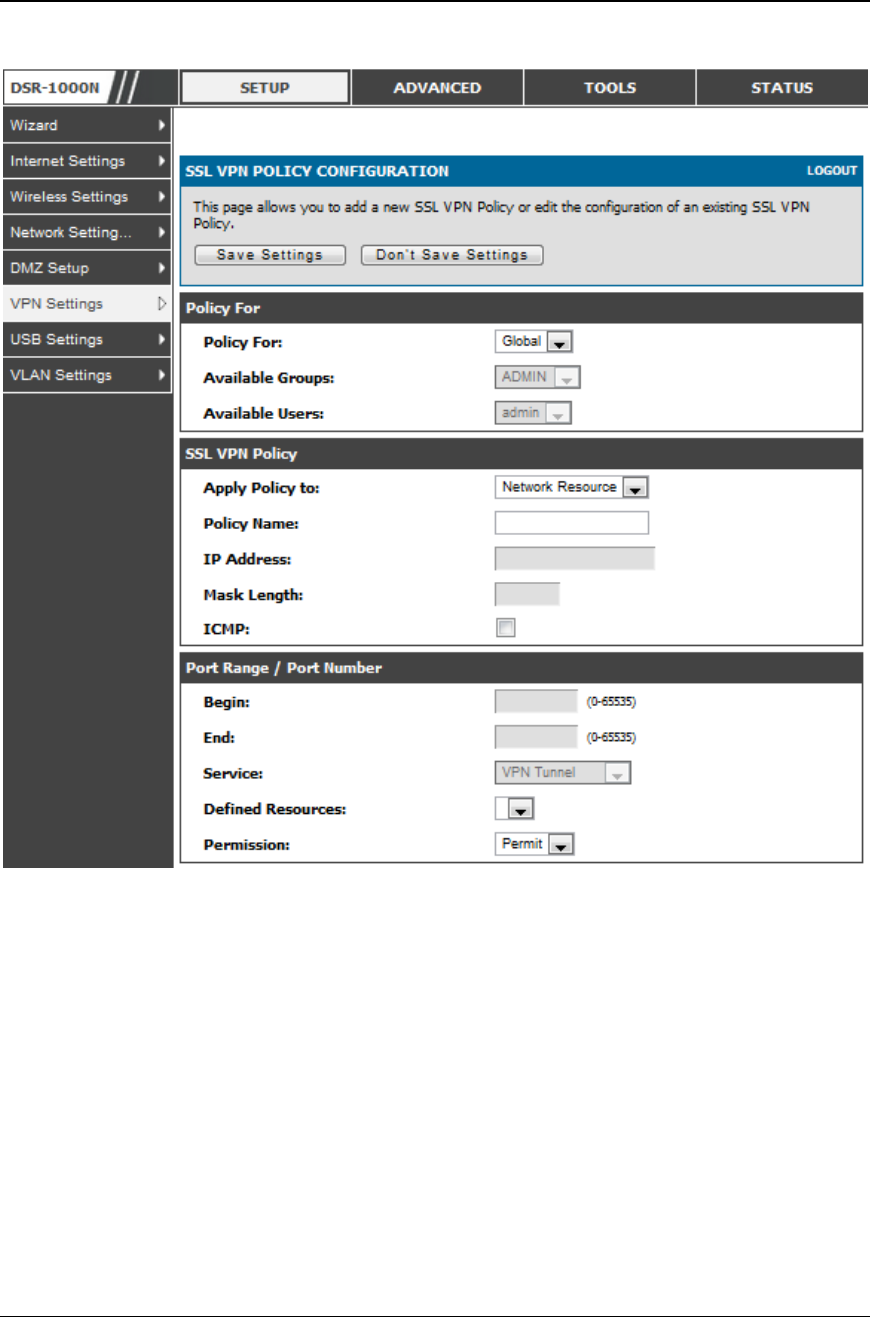
Unified Services Router User Manual
140
Figure 94: SSL VPN policy configurati on
To configure a policy for a single user or group of users, e nter the following
information:
Policy for: The policy can be assigned to a group of users, a single user, or all
users (making it a global policy). To customize the policy for specific users or
groups, the user can select from the Available Groups and Available Users
drop down.
Apply policy to: This refers to the LAN resources managed by the DSR, and
the policy can provide (or prevent) access to network resources, IP address, IP
network, etc.
Policy name: This field is a unique name for identifying the po licy. IP
address: Required when the governed resource is identified by its IP address
or range of addresses.
Mask Length: Required when the governed resource is identified by a range
of addresses within a subnet.

Unified Services Router User Manual
141
ICMP: Select this option to include ICMP traffic
Port range: If the policy governs a type of traffic, this field is used for
defining TCP or UDP port number(s) corresponding to the governed traffic.
Leaving the starting and ending port range blank corresponds to all UDP and
TCP traffic.
Service: This is the SSL VPN service made available by this policy. The
services offered are VPN tunnel, port forwarding or both.
Defined resources: This policy can provide access to specific network
resources. Network resources must be configured in advance of creating the
policy to make them available for selection as a defined resource. Network
resources are created with the following information
Permission: The assigned resources defined by this policy can be explicitly
permitted or denied.
7.2.1 Using Network Resources
Setup > VPN Settings > SSL VPN Server > Resources
Network resources are services or groups of LAN IP addresses that are used to
easily create and configure SSL VPN policies. This shortcut saves time when
creating similar policies for multiple remote SSL VPN users.
Adding a Network Resource involves creating a unique name to identify the
resource and assigning it to one or all of the supported SSL services. Once this is
done, editing one of the created network resources allows you to configure the
object type (either IP address or IP range) associated with the service. The Network
Address, Mask Length, and Port Range/Port Number can all be defined for this
resource as required. A network resource can be defined by configuring the
following in the GUI:
Resource name: A unique identifier name for the resource.
Service: The SSL VPN service corresponding to the resource (VPN tunnel,
Port Forwarding or All).
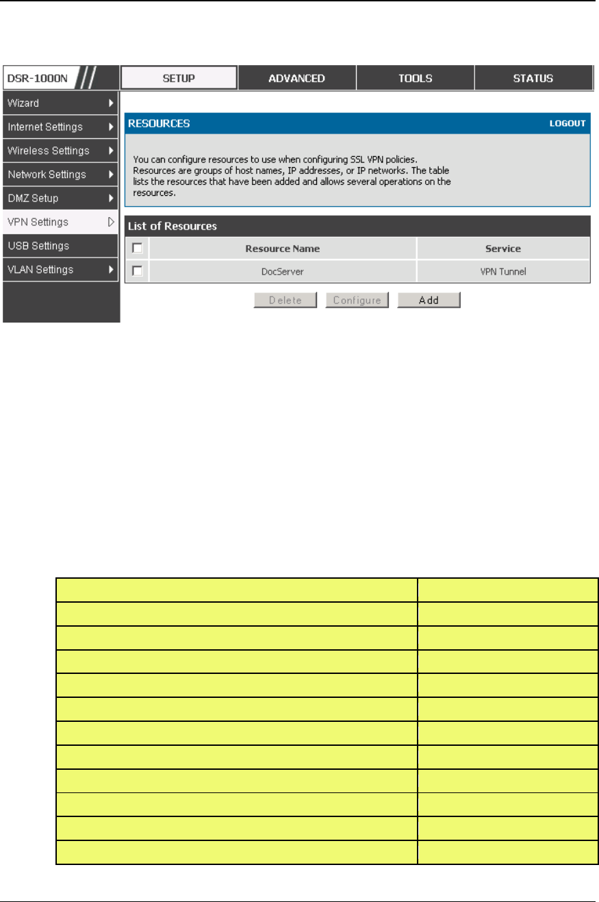
Unified Services Router User Manual
142
Figure 95: List of conf igured resources, which are available to assign to
SSL VPN policies
7.3 Application Port Forwarding
Setup > VPN Settings > SSL VPN Server > Port Forwarding
Port forwarding allows remote SSL users to access specified network applications or
services after they login to the User Portal and launch the Port For warding service.
Traffic from the remote user to the router is detected and re-routed based on
configured port forwarding rules.
Internal host servers or TCP applications must be specified as being made accessible
to remote users. Allowing access to a LAN server requires entering the local server IP
address and TCP port number of the application to be tunnelled. The table below lists
some common applications and corresponding TCP port numbers:
TCP Application
Port Number
FTP Data (usually not needed)
20
FTP Control Protocol
21
SSH
22
Telnet
23
SMTP (send mail)
25
HTTP (web)
80
POP3 (receive mail)
110
NTP (network time protocol)
123
Citrix
1494
Terminal Services
3389
VNC (virtual network computing)
5900 or 5800

Unified Services Router User Manual
143
As a convenience for remote users, the hostname (FQDN) of the network server can
be configured to allow for IP address resolution. This host name resolution provides
users with easy-to-remember FQDN’s to access TCP applications instead of error -
prone IP addresses when using the Port Forwarding service through the SSL User
Portal.
To configure port forwarding, following are required:
Local Server IP address: The IP address of the local server which is hosting
the application.
TCP port: The TCP port of the application
Once the new application is defined it is displayed in a list of configured applications
for port forwarding.
allow users to access the private network servers by using a hostname instead of an IP
address, the FQDN corresponding to the IP address is defined in the port forwarding
host configuration section.
Local server IP address: The IP address of the local server hosting the
application. The application should be configured in advance.
Fully qualified domain name: The domain name of the internal server is to be
specified
Once the new FQDN is configured, it is displayed in a list of configured hosts for port
forwarding.
Defining the hostname is optional as minimum requirement for port forwarding is
identifying the TCP application and local server IP address. The local server IP
address of the configured hostname must match the IP address of the configured
application for port forwarding.
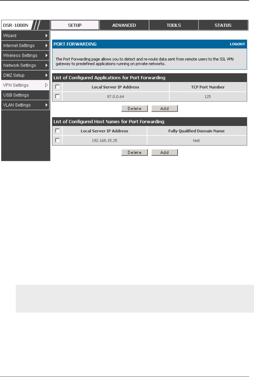
Unified Services Router User Manual
144
Figure 96: Li st of Available Applica tions for SSL P ort Forwarding
7.4 SSL VPN Client Configuration
Setup > VPN Settings > SSL VPN Client > SSL VPN Client
An SSL VPN tunnel client provides a point -to-point connection between the browser -
side machine and this router. When a SSL VPN client is launched from the user
portal, a "network adapter" with an IP address from the corporate subnet, DNS and
WINS settings is automatically created. This allows local applications to access
services on the private network without any special network configuration on the
remote SSL VPN client machine.
It is important to ensure that the virtual (PPP) interface address of the VPN tunnel
client does not conflict with physical devices on the LAN. The IP address range for
the SSL VPN virtual network adapter should be either in a different subnet or non -
overlapping range as the corporate LAN.
The IP addresses of the client’s network interfaces (Ethernet, Wireless, etc.) cannot
be identical to the router’s IP address or a server on the corporate LAN that is
being accessed through the SSL VPN tunnel.
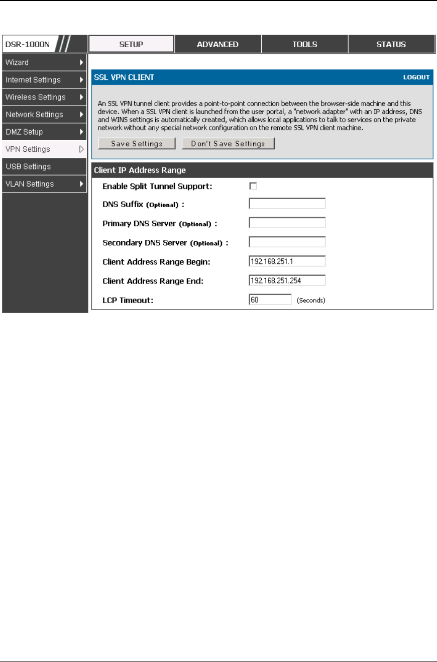
Unified Services Router User Manual
145
Figure 97: SSL VPN client adapter a nd access configuration
The router allows full tunnel and split tunnel support. Full tunnel mode just sends all
traffic from the client across the VPN tunnel to the router. Split tunnel mode only
sends traffic to the private LAN based on pre-specified client routes. These client
routes give the SSL client access to specific private networks, thereby allowing access
control over specific LAN services.
Client level configuration supports the following:
Enable Split Tunnel Support: With a split tunnel, only resources which are
referenced by client routes can be accessed over the VPN tunnel. With full
tunnel support (if the split tunnel option is disabled the DSR acts in full
tunnel mode) all addresses on the private network are accessible over the
VPN tunnel. Client routes are not required.
DNS Suffix: The DNS suffix name which will be given to the SSL VPN
client. This configuration is optional.
Primary DNS Server: DNS server IP address to set on the network adaptor
created on the client host. This configuration is optional.
Secondary DNS Server: Secondary DNS server IP address to set on the
network adaptor created on the client host. This configuration is optional.
Client Address Range Begin: Clients who connect to the tunnel get a DHCP
served IP address assigned to the network adaptor from the range of addresses
beginning with this IP address
Client Address Range End: The ending IP address of the DHCP range of
addresses served to the client network adaptor.
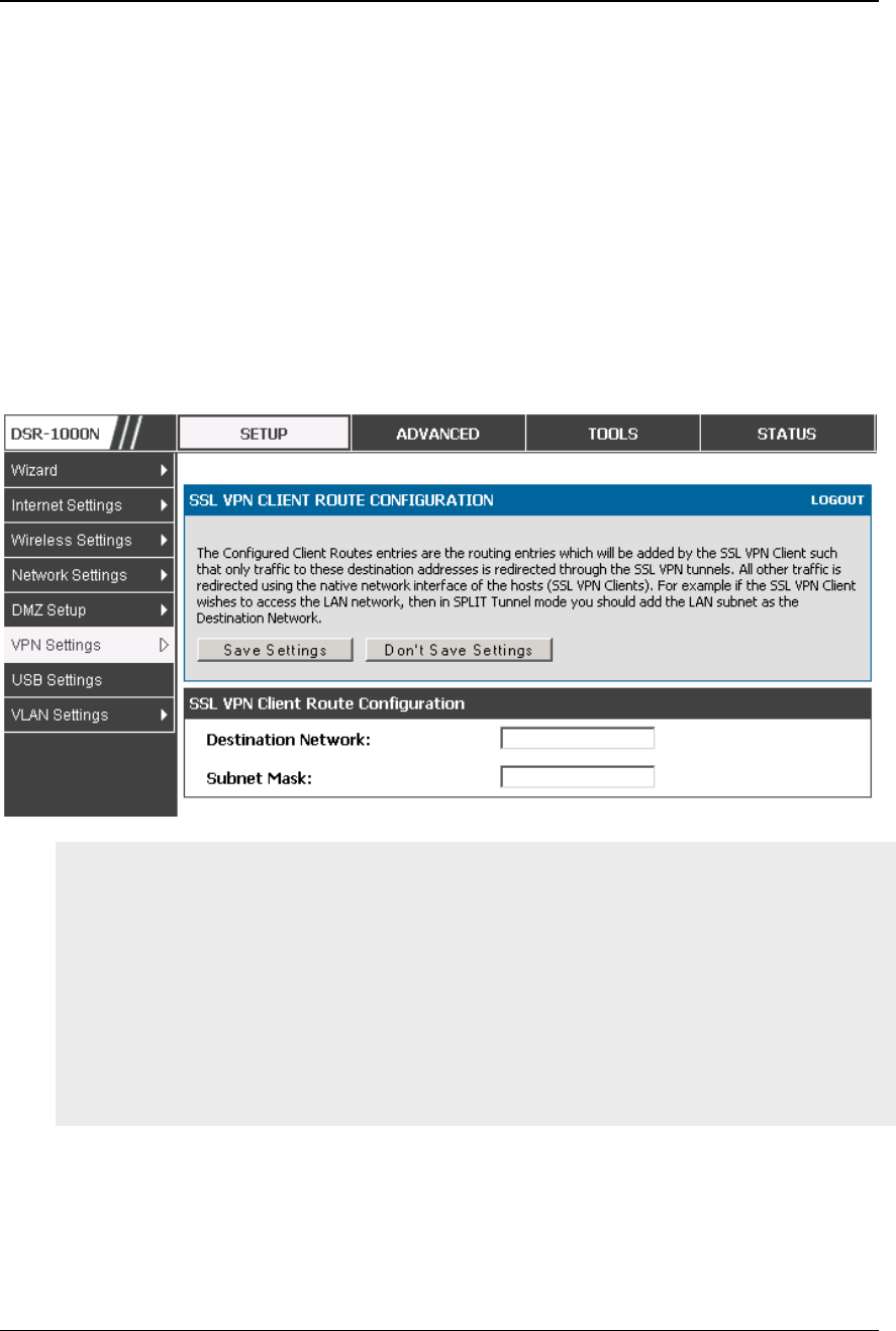
Unified Services Router User Manual
146
Setup > VPN Settings > SSL VPN Client > Configured Client Routes
If the SSL VPN client is assigned an IP address in a different subnet than the
corporate network, a client route must be added to allow access to the private LAN
through the VPN tunnel. As well a static route on the private LAN’s firewall
(typically this router) is needed to forward private traffic through the VPN Firewall to
the remote SSL VPN client. When split tunnel mode is enabled, the user is required to
configure routes for VPN tunnel clients:
Destination network: The network address of the LAN or the subnet
information of the destination network from the VPN tunnel clients’
perspective is set here.
Subnet mask: The subnet information of the destination network is set here.
Figure 98: Configured client routes only apply in spli t t unnel mode
Steps to Install/Uninstall SSLVPN tunnel in MAC OS
1.Open terminal and run "visudo" as root and it will open sudoers file
2. Add "username ALL=NOPASSWD: /usr/sbin/chown,/bin/chmod,/bin/rm" at the
bottom of the sudoers file, save and close the file. (Username is the user name of
the MAC account but not SSLVPN user name).
While uninstalling SSLVPN tunnel, when it asks for password, enter the MAC user
account password but not root password or sslvpn user password
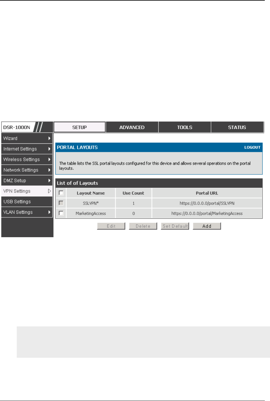
Unified Services Router User Manual
147
7.5 User Portal
Setup > VPN Settings > SSL VPN Client > SSL VPN Client Portal
When remote users want to access the private network through an SSL tunnel (either
using the Port Forwarding or VPN tunnel service), they login through a user portal.
This portal provides the authentication fields to provide the appropriate access levels
and privileges as determined by the router administrator. The domain where the user
account is stored must be specified, and the domain determines the authentication
method and portal layout screen presented to the remote user.
Figure 99: Li st of configured SSL VPN portal s. The configured portal
can then be associated with an authentication domai n
7.5.1 Creating Portal Layouts
Setup > VPN Settings > SSL VPN Server > Portal Layouts
The router allows you to create a custom page for remote SSL VPN users that is
presented upon authentication. There are various fields in the portal that are
customizable for the domain, and this allows the router administ rator to
communicate details such as login instructions, available services, and other usage
details in the portal visible to remote users. During domain setup, configured portal
layouts are available to select for all users authenticated by the domain.
The default portal LAN IP address is https://192.168.10.1/scgi-
bin/userPortal/portal. This is the same page that opens when the “User Portal”
link is clicked on the SSL VPN menu of the router GUI.
The router administrator creates and edits portal layouts from the configuration pages
in the SSL VPN menu. The portal name, title, banner name, and banner contents are
all customizable to the intended users for this portal. The portal name is appended to

Unified Services Router User Manual
148
the SSL VPN portal URL. As well, the users assigned to this portal (through their
authentication domain) can be presented with one or more of the router’s supported
SSL services such as the VPN Tunnel page or Port Forwarding page.
To configure a portal layout and theme, following information is needed:
Portal layout name: A descriptive name for the custom portal that is being
configured. It is used as part of the SSL portal URL.
Portal site title: The portal web browser window title that appears w hen the
client accesses this portal. This field is optional.
Banner title: The banner title that is displayed to SSL VPN clients prior to
login. This field is optional.
Banner message: The banner message that is displayed to SSL VPN clients
prior to login. This field is optional.
Display banner message on the login page: The user has the option to either
display or hide the banner message in the login page.
HTTP meta tags for cache control: This security feature prevents expired web
pages and data from being stored in the client’s web browser cache. It is
recommended that the user selects this option.
ActiveX web cache cleaner: An ActiveX cache control web cleaner can be
pushed from the gateway to the client browser whenever users login to this
SSL VPN portal.
SSL VPN portal page to display: The User can either enable VPN tunnel page
or Port Forwarding, or both depending on the SSL services to display on this
portal.
Once the portal settings are configured, the newly configured portal is added to the
list of portal layouts.
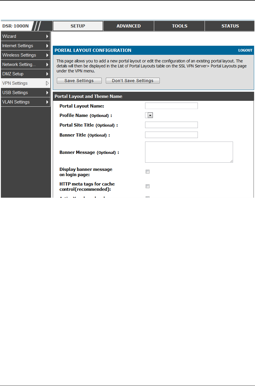
Unified Services Router User Manual
149
Figure 100: SSL VPN Portal configuration

Unified Services Router User Manual
150
Chapter 8. Advanced Configuration
Tools
8.1 USB Device Setup
Setup > USB Settings > USB Status
The DSR Unified Services Router has a USB interface for printer access, file sharing
and on the DSR-1000 / DSR-1000N models 3G modem support.
There is no configuration on the GUI to enable USB device support. Upon inserting
your USB storage device, printer cable or 3G modem the DSR router will
automatically detect the type of connected peripheral.
USB Mass Storage: also referred to as a “share port”, files on a USB disk
connected to the DSR can be accessed by LAN users as a network drive.
USB Printer: The DSR can provide the LAN with access to printers connected
through the USB. The printer driver will have to be installed on the LAN host
and traffic will be routed through the DSR between the LAN and printer.
USB 3G modem: A 3G modem dongle can be plugged in and used as a secondary
WAN. Load balancing, auto-failover, or primary WAN access can be configured
through the 3G interface.
To configure printer on a Windows machine, follow below given steps:
Click 'Start' on the desktop.
Select ‘Printers and faxes’ option.
Right click and select 'add printer' or click on 'Add printer' present at the left
menu.
Select the 'Network Printer' radio button and click next (select "device isn't listed
in case of Windows7").
Select the 'Connect to printer using URL' radio button ('Select a shared printer by
name ‘in case of Windows 7) and give the following URL http://<Router's LAN
IP address>:631/printers/<Model Name> (Model Name can be found in the USB
status page of router's GUI).
Click 'next' and select the appropriate driver from the displayed list.
Click on 'next' and 'finish' to complete adding t he printer.
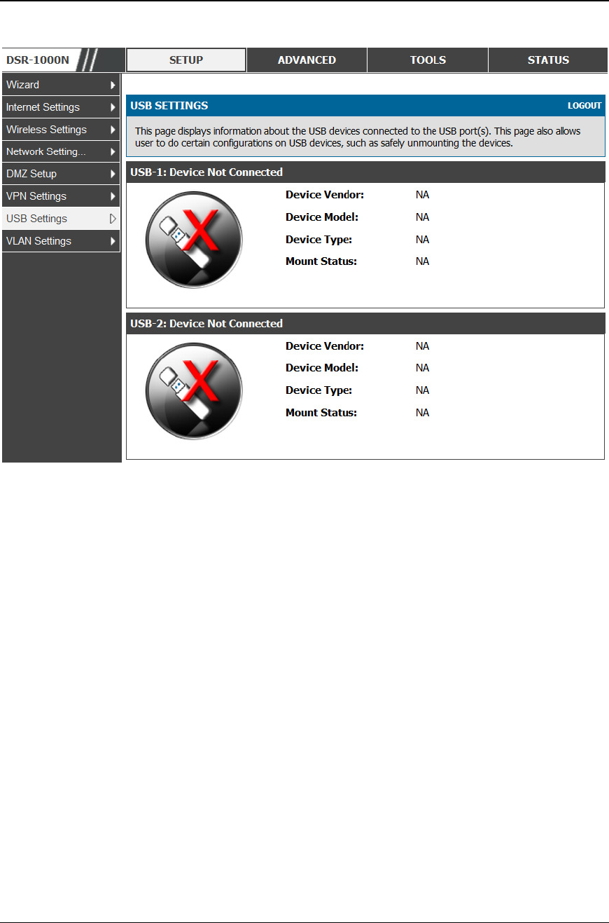
Unified Services Router User Manual
151
Figure 101: USB Device Detectio n
8.2 USB share port
Setup > USB Settings > USB SharePort
This page allows configure the SharePort feature available in this router.
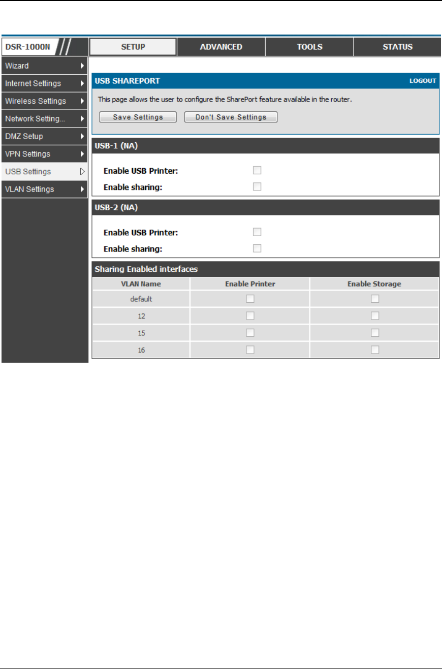
Unified Services Router User Manual
152
Figure 102: USB SharePort
USB-1:
Enable USB Printer: Select this option to allow the USB printer connected to the
router to be shared across the network.
The USB printer can be accessed on any LAN host (with appropriate printer driver
installed) connected to the router by using the following command in the host's add
printers window
http://<Router's IP:631>/printers/<Device Model> (Device Model can be found in the
USB settings page).
Enable Sharing: Select this option to allow the USB storage device connected to the
router to be shared across the network.
USB-2:
Enable USB Printer: Select this option to allow the USB printer connected to the
router to be shared across the network.
The USB printer can be accessed on any LAN host (with appropriate printer driver
installed) connected to the router by using the following command in the host's add
printers window
http://<Router's IP:631>/printers/<Device Model> (Device Model can be found in the
USB settings page).
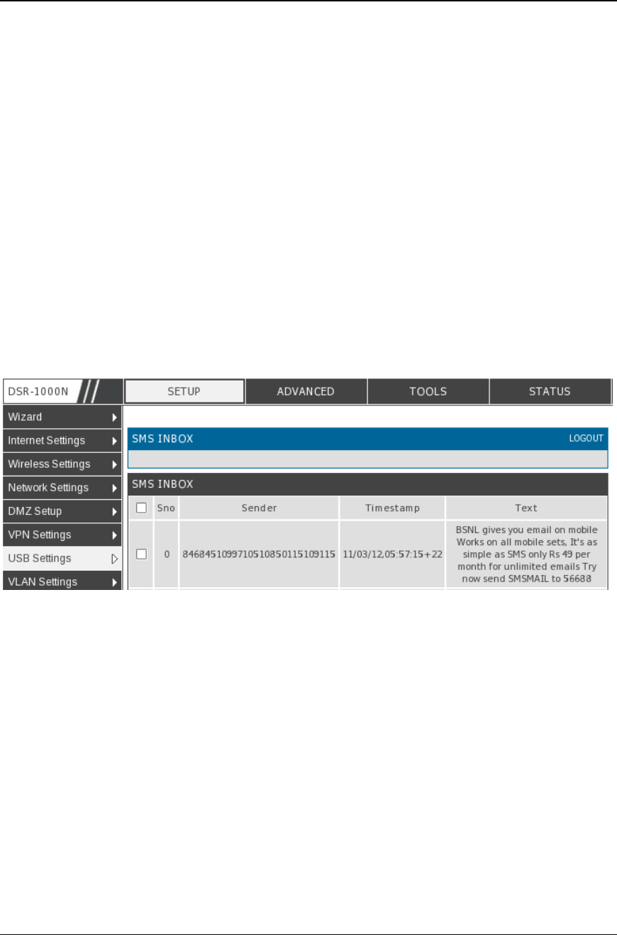
Unified Services Router User Manual
153
Enable Sharing: Select this option to allow the USB storage device connected t o the
router to be shared across the network.
Sharing Enabled interfaces:
The LAN interfaces on which USB sharing is enabled, atleast one interface must be
selected to begin sharing.
Enable Printer: Enables printer sharing on the selected interface.
Enable Storage: Enables storage device sharing on the selected interface.
8.3 SMS service
Setup > USB Settings > SMS Service
The DSR Unified Services Router has a USB interface to connect 3G modem support
to send and receive Short Messaging Service. The received messages can be seen in
the Inbox and allows the user to create a new SMS. If WAN3 is used in dedicated wan
mode, load balancing mode or if 3G USB Device is not connected to router then the
controls on this page will be greyed out.
Figure 103: SMS Service – Send SMS
The following details are displayed in SMS INBOX page:
Sno: Displays the serial number of message in the inbox.
Sender: Displays the sender of the particular message.
TimeStamp: Displays the time when the message was se nt
Text: Displays the content of the particular Message.
The following actions are performed:
Delete: Deletes the SMS having that particular Sno. Only one message can be
deleted at a time.
Refresh: Updates the inbox with new SMS (if any).
Reply: Lets the user create a new SMS in reply to a particular message by the
selected sender. “Receiver" field in the createSms.htm page is filled with the
sender's number.
Forward: Lets the user forward a selected SMS. "Text Message" field in the
createSms.htm page is filled with the "Text" of the selected message.
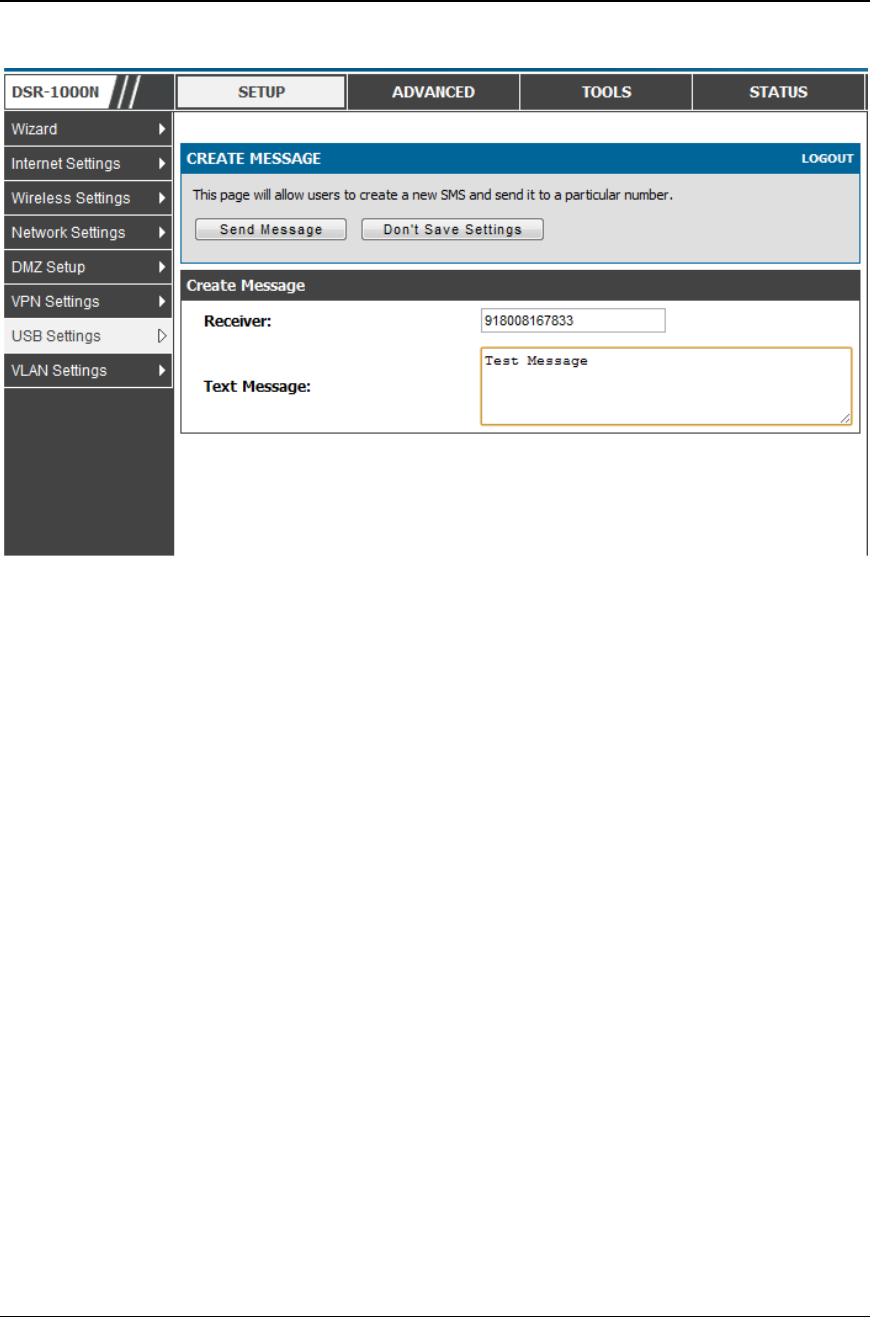
Unified Services Router User Manual
154
Figure 104: SMS Service – Receive SMS
The following details to be provided in Create Message page:
Receiver: Enter the phone number of the intended receiver of the message.
Text Message: Enter the body of the message here
Click Send Message to send the message.
Click Don't Save Settings to reset Receiver and Text Message fields.
8.4 Authentication Certificates
Advanced > Certificates
This gateway uses digital certificates for IPsec VPN authentication as well as SSL
validation (for HTTPS and SSL VPN authentication). You can obtain a digital
certificate from a well-known Certificate Authority (CA) such as VeriSign, or
generate and sign your own certificate using functionality available on this gateway.
The gateway comes with a self-signed certificate, and this can be replaced by one
signed by a CA as per your networking requirements. A CA certificate provides
strong assurance of the server’s identity and is a requirement for most corporate
network VPN solutions.
The certificates menu allows you to view a list of certificates (both from a CA and
self-signed) currently loaded on the gateway. The following certificate data is
displayed in the list of Trusted (CA) certificates:
CA Identity (Subject Name): The certificate is issued to this person or organization
Issuer Name: This is the CA name that issued this certificate
Expiry Time: The date after which this Trusted certificate becomes invalid
A self certificate is a certificate issued by a CA identifying your device (or self -
signed if you don’t want the identity protection of a CA). The Active Self Certificate
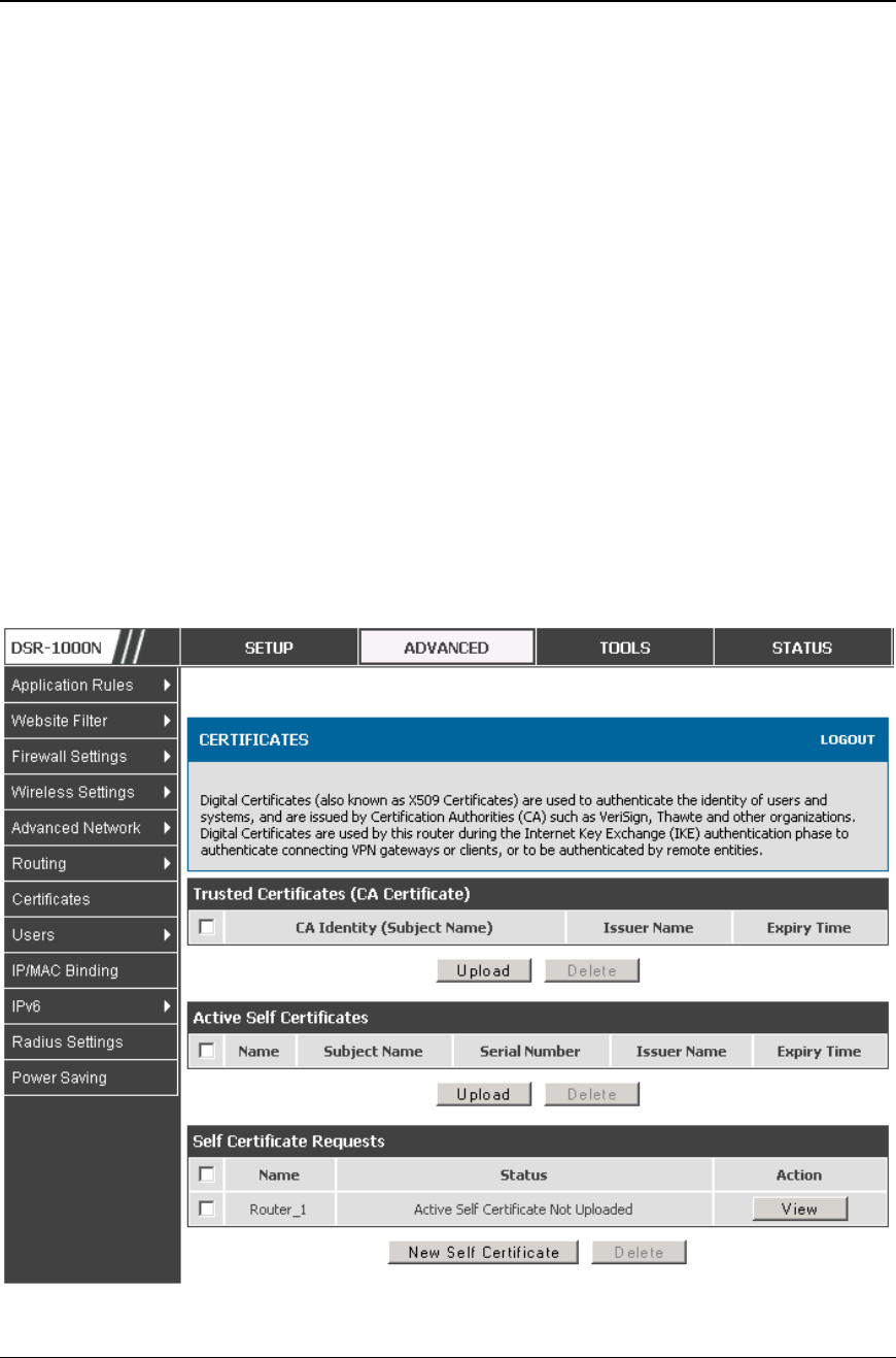
Unified Services Router User Manual
155
table lists the self certificates currently loaded on the gateway. The following
information is displayed for each uploaded self cer tificate:
Name: The name you use to identify this certificate, it is not displayed to IPsec
VPN peers or SSL users.
Subject Name: This is the name that will be displayed as the owner of this
certificate. This should be your official registered or company n ame, as IPsec or
SSL VPN peers are shown this field.
Serial Number: The serial number is maintained by the CA and used to identify
this signed certificate.
Issuer Name: This is the CA name that issued (signed) this certificate
Expiry Time: The date after which this signed certificate becomes invalid – you
should renew the certificate before it expires.
To request a self certificate to be signed by a CA, you can generate a Certificate
Signing Request from the gateway by entering identification parameters an d passing it
along to the CA for signing. Once signed, the CA’s Trusted Certificate and signed
certificate from the CA are uploaded to activate the self -certificate validating the
identity of this gateway. The self certificate is then used in IPsec and SSL
connections with peers to validate the gateway’s authenticity.
Figure 105: Certificate summary for IPsec and HTTPS ma nagement
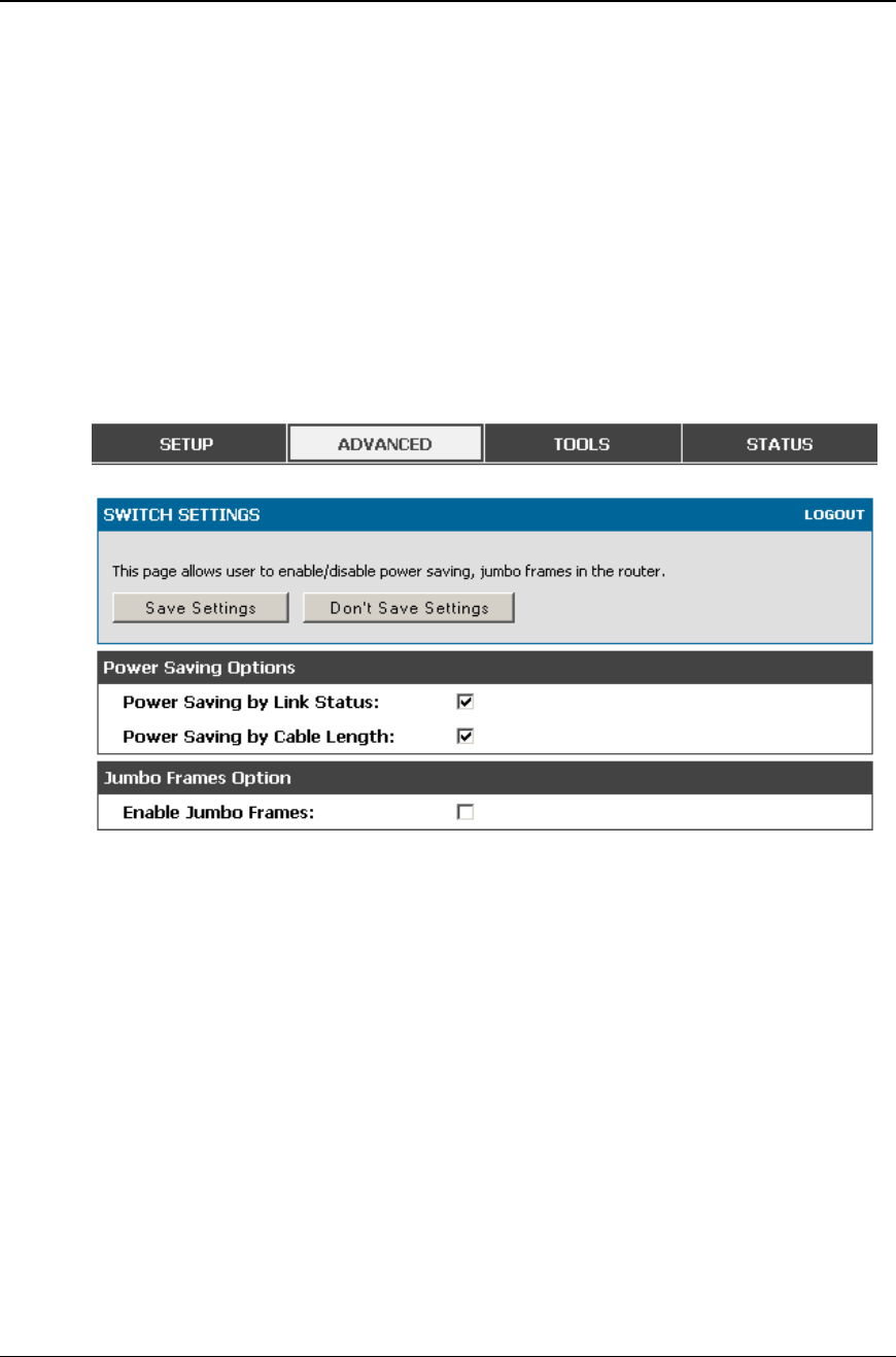
Unified Services Router User Manual
156
8.5 Advanced Switch Configuration
The DSR allows you to adjust the power consumption of the hardware b ased on your
actual usage. The two “green” options available for your LAN switch are Power
Saving by Link Status and Length Detection State. With “Power Saving by Link
Status” option enabled, the total power consumption by the LAN switch is dependent
function of on the number of connected ports. The overall current draw when a single
port is connected is less than when all the ports are connected. With “Length
Detection State” option enabled, the overall current supplied to a LAN port is reduced
when a smaller cable length is connected on a LAN port.
Jumbo Frames support can be configured as an advanced switch configuration. Jumbo
frames are Ethernet frames with more than 1500 bytes of payload. When this option is
enabled, the LAN devices can exchange infor mation at Jumbo frames rate.
Figure 106: Advanced Switch Settings
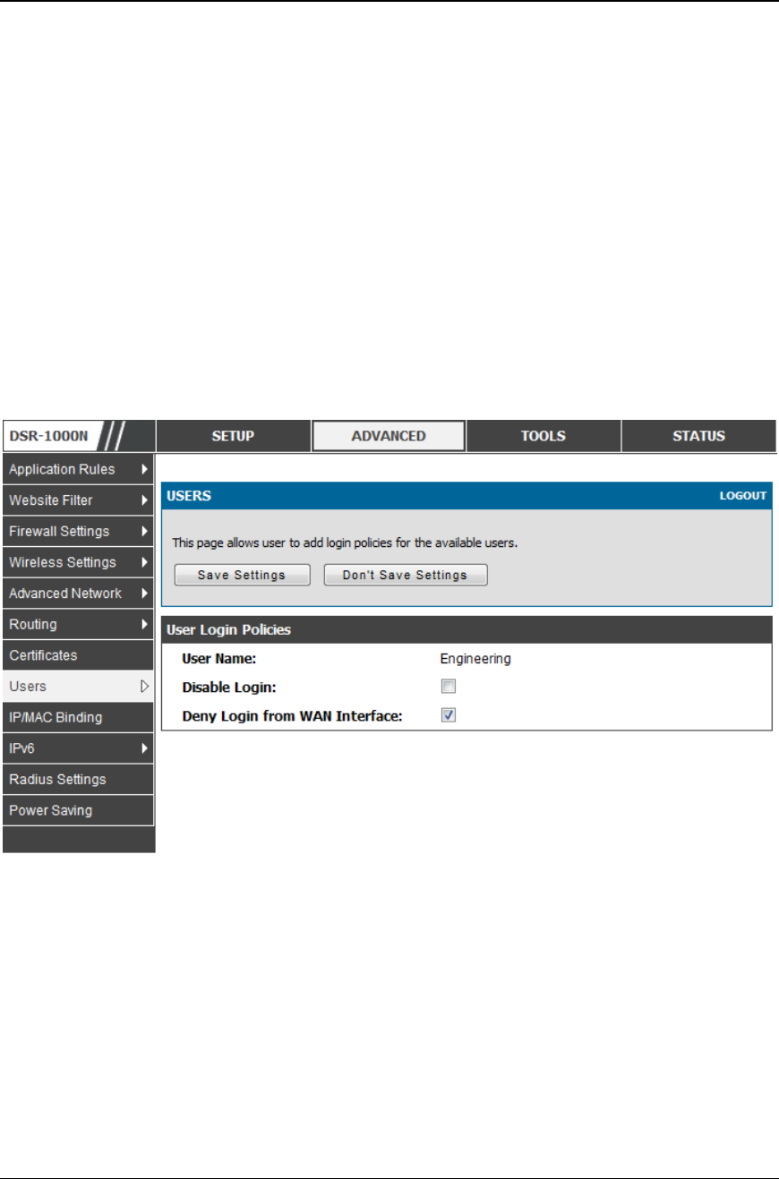
Unified Services Router User Manual
157
Chapter 9. Administration &
Management
9.1 Configuration Access Control
The primary means to configure this gateway via the browser -independent GUI. The
GUI can be accessed from LAN node by using the gateway’s LAN IP address and
HTTP, or from the WAN by using the gateway’s WAN IP address and HTTPS (HTTP
over SSL).
Administrator and Guest users are permitted to login to the router’s management
interface. The user type is set in the Advanced > Users > Users page. The Admin or
Guest user can be configured to access the router GUI from the LAN or the Internet
(WAN) by enabling the corresponding Login Policy.
Figure 107: User Login policy c onfiguration
9.1.1 Admin Settings
Tools > Admin > Admin settings
This page allows to provide the name of the router.
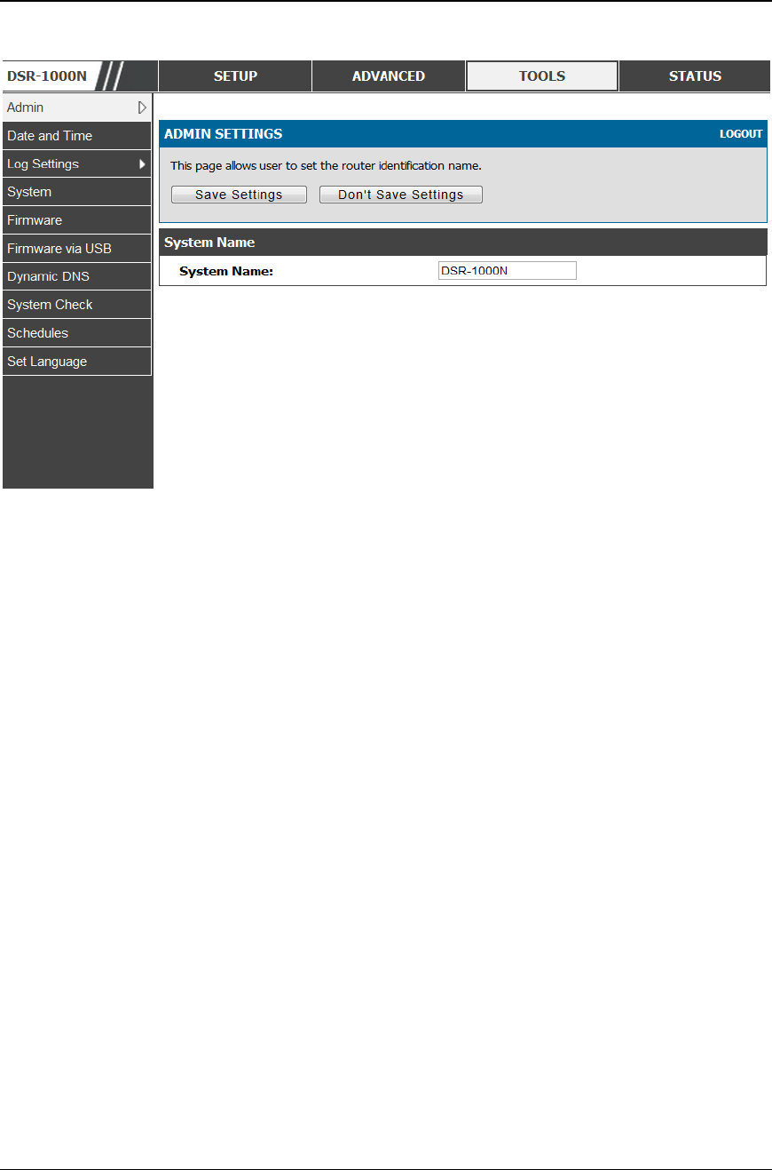
Unified Services Router User Manual
158
Figure 108: Admin Settings
9.1.2 Remote Management
Tools > Admin > Remote Management
Both HTTPS and telnet access can be restricted to a subset of IP addresses. The
router administrator can define a known PC, single IP address or range of IP
addresses that are allowed to access the GUI with HTTPS. The opened port for SSL
traffic can be changed from the default of 443 at the same time as d efining the
allowed remote management IP address range.
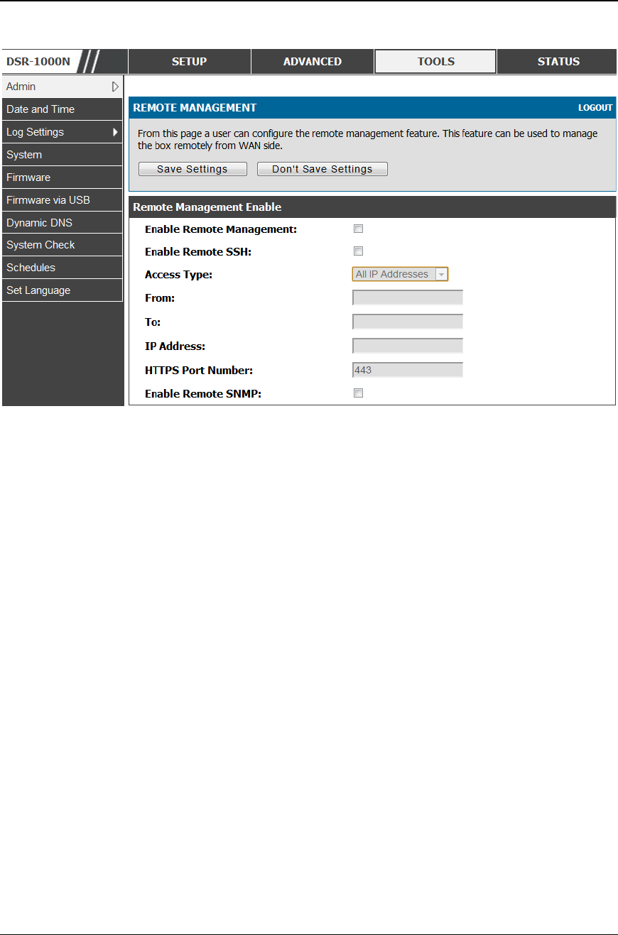
Unified Services Router User Manual
159
Figure 109: Re mote Manage ment from the WAN
9.1.3 CLI Access
In addition to the web-based GUI, the gateway supports SSH and Telnet
management for command-line interaction. The CLI login credentials are shared
with the GUI for administrator users. To access the CLI, type “cli” in the SSH or
console prompt and login with administrator user credentials.
9.2 SNMP Configuration
Tools > Admin > SNMP
SNMP is an additional management tool that is useful when multiple routers in a
network are being managed by a central Master system . When an external SNMP
manager is provided with this router’s Management Information Base (MIB) file, the
manager can update the router’s hierarchal variables to view or update configuration
parameters. The router as a managed device has an SNMP agent that allows the MIB
configuration variables to be accessed by the Master (the SNMP manager). The
Access Control List on the router identifies managers in the network that have read-
only or read-write SNMP credentials. The Traps List outlines the port over which
notifications from this router are provided to the SNMP community (managers) and
also the SNMP version (v1, v2c, v3) for the trap.
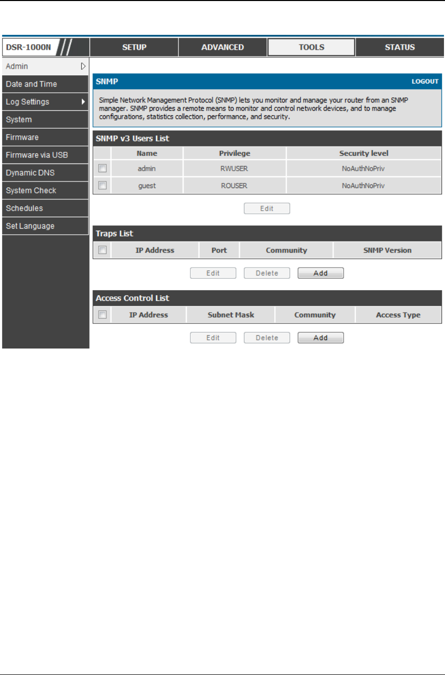
Unified Services Router User Manual
160
Figure 110: SNMP Users, Traps, a nd Access Control
Tools > Admin > SNMP System Info
The router is identified by an SNMP manager via the System Information. The
identifier settings The SysName set here is also used to identify the router for SysLog
logging.
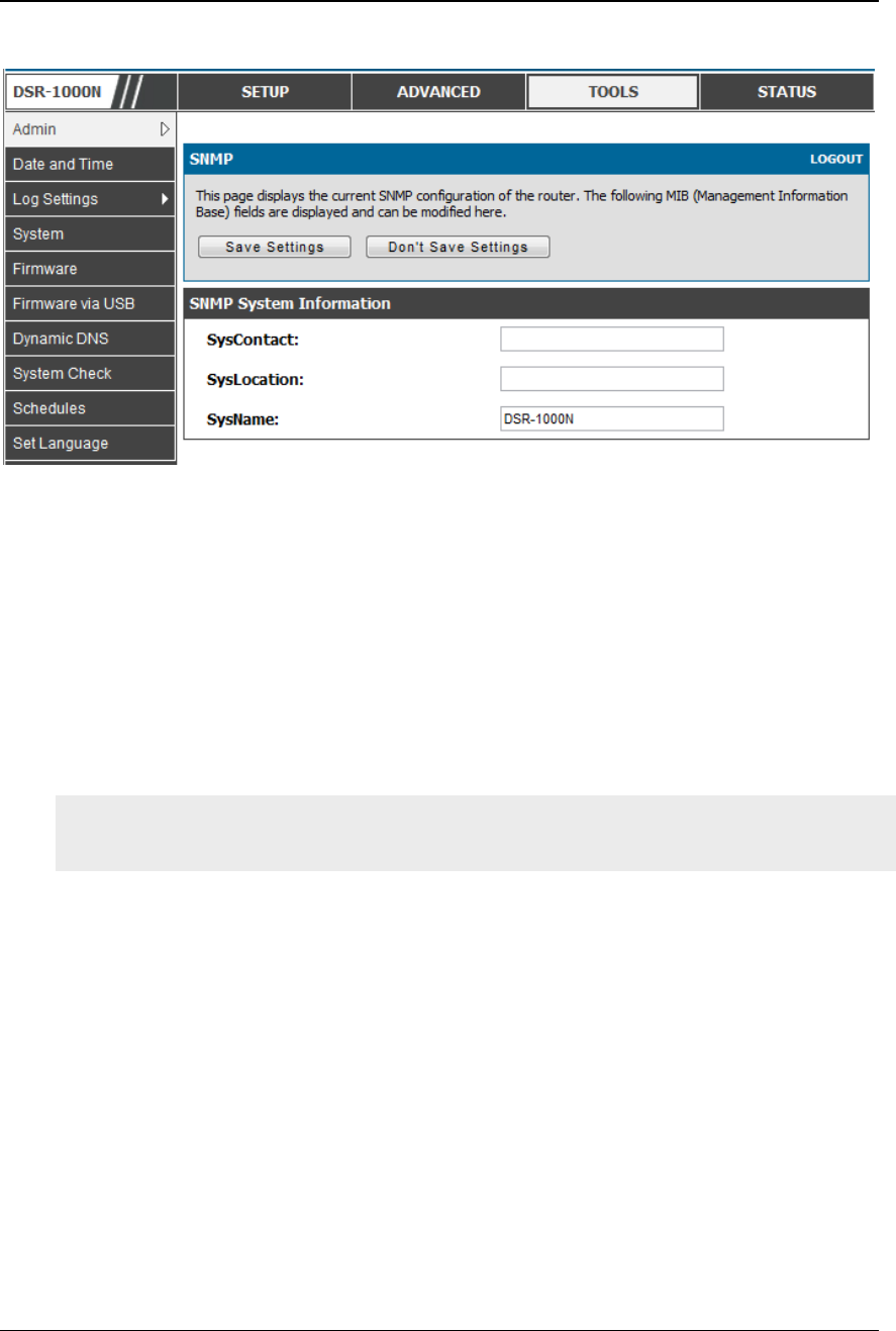
Unified Services Router User Manual
161
Figure 111: SNMP system information f or this router
9.3 Configuring Time Zone and NTP
Tools > Date and Time
You can configure your time zone, whether or not to adjust for Daylight Savings
Time, and with which Network Time Protocol (NTP) server to synchronize the date
and time. You can choose to set Date and Time manually, which will store the
information on the router’s real time clock (RTC). If the router has access to the
internet, the most accurate mechanism to set the router time is to enable NTP server
communication.
Accurate date and time on the router is critical for firewall schedules, Wi -Fi power
saving support to disable APs at certain times of the day, and accurate logging.
Please follow the steps below to configure the NTP server:
1. Select the router’s time zone, relative to Greenwich Mean Time (GMT).
2. If supported for your region, click to Enable Daylight Savings.
3. Determine whether to use default or custom Network Time Protocol (NTP) servers. If
custom, enter the server addresses or FQDN.
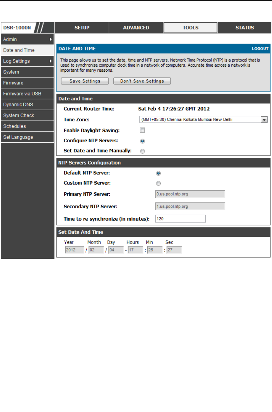
Unified Services Router User Manual
162
Figure 112: Date, Time, and NTP server setup
9.4 Log Configuration
This router allows you to capture log messages for traffic through the firewall, VPN,
and over the wireless AP. As an administrator you can monitor t he type of traffic that
goes through the router and also be notified of potential attacks or errors when they
are detected by the router. The following sections describe the log configuration
settings and the ways you can access these logs.
9.4.1 Defining What to Log
Tools > Log Settings > Logs Facility
The Logs Facility page allows you to determine the granularity of logs to receive
from the router. There are three core components of the router, referred to as
Facilities:

Unified Services Router User Manual
163
Kernel: This refers to the Linux kernel. Log messages that correspond to this
facility would correspond to traffic through the firewall or network stack.
System: This refers to application and management level features available on this
router, including SSL VPN and administrator changes for ma naging the unit.
Wireless: This facility corresponds to the 802.11 driver used for providing AP
functionality to your network.
Local1-UTM: This facility corresponds to IPS (Intrusion Prevention System)
which helps in detecting malicious intrusion attempts from the WAN.
For each facility, the following events (in order of severity) can be logged:
Emergency, Alert, Critical, Error, Warning, Notification, Information, Debugging.
When a particular severity level is selected, all events with severity equal to a nd
greater than the chosen severity are captured. For example if you have configured
CRITICAL level logging for the Wireless facility, then 802.11 logs with severities
CRITICAL, ALERT, and EMERGENCY are logged. The severity levels available
for logging are:
EMERGENCY: system is unusable
ALERT: action must be taken immediately
CRITICAL: critical conditions
ERROR: error conditions
WARNING: warning conditions
NOTIFICATION: normal but significant condition
INFORMATION: informational
DEBUGGING: debug-level messages
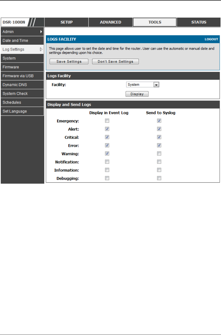
Unified Services Router User Manual
164
Figure 113: Facility settings for Logging
The display for logging can be customized based on where the logs are sent, either
the Event Log viewer in the GUI (the Event Log viewer is in the Status > Logs
page) or a remote Syslog server for later review. E-mail logs, discussed in a
subsequent section, follow the same configuration as logs configured for a Syslog
server.
Tools > Log Settings > Logs Configuration
This page allows you to determine the type of traffic throug h the router that is
logged for display in Syslog, E-mailed logs, or the Event Viewer. Denial of service
attacks, general attack information, login attempts, dropped packets, and similar
events can be captured for review by the IT administrator.
Traffic through each network segment (LAN, WAN, DMZ) can be tracked based on
whether the packet was accepted or dropped by the firewall.
Accepted Packets are those that were successfully transferred through the
corresponding network segment (i.e. LAN to WAN). This option is particularly
useful when the Default Outbound Policy is “Block Always” so the IT admin can
monitor traffic that is passed through the firewall.
Example: If Accept Packets from LAN to WAN is enabled and there is a
firewall rule to allow SSH traffic from LAN, then whenever a LAN machine

Unified Services Router User Manual
165
tries to make an SSH connection, those packets will be accepted and a
message will be logged. (Assuming the log option is set to Allow for the
SSH firewall rule.)
Dropped Packets are packets that were intentionally blocked from being transferred
through the corresponding network segment. This option is useful when the Default
Outbound Policy is “Allow Always”.
Example: If Drop Packets from LAN to WAN is enabled and there is a
firewall rule to block SSH traffic from LAN, then whenever a LAN machine
tries to make an SSH connection, those packets will be dropped and a
message will be logged. (Make sure the log option is set to allow for this
firewall rule.)
Enabling accepted packet logging through the firewall may gen erate a significant
volume of log messages depending on the typical network traffic. This is
recommended for debugging purposes only.
In addition to network segment logging, unicast and multicast traffic can be logged.
Unicast packets have a single destination on the network, whereas broadcast (or
multicast) packets are sent to all possible destinations simultaneously. One other
useful log control is to log packets that are dropped due to configured bandwidth
profiles over a particular interface. This data will indicate to the admin whether the
bandwidth profile has to be modified to account for the desired internet traffic of
LAN users.
Unified Services Router User Manual
166
Figure 114: Log configuration options for traffic throug h router
Tools > Log Settings > IPv6 logging
This page allows you to configure the IPv6 logging
Unified Services Router User Manual
167
Figure 115: IPv6 Log conf iguration options for traff ic through ro uter
9.4.2 Sending Logs to E-mail or Syslog
Tools > Log Settings > Remote Logging
Once you have configured the type of logs that you want the router to collect, they
can be sent to either a Syslog server or an E -Mail address. For remote logging a key
configuration field is the Remote Log Identifier. Every logged message will contain
the configured prefix of the Remote Log Identifier, so that syslog servers or email
addresses that receive logs from more than one router can sort for the relevant
device’s logs.
Once you enable the option to e -mail logs, enter the e-mail server’s address (IP
address or FQDN) of the SMT P server. The router will connect to this server when
sending e-mails out to the configured addresses. The SMTP port and return e-mail
addresses are required fields to allow the router to package the logs and send a valid
e-mail that is accepted by one of the configured “send-to” addresses. Up to three e-
mail addresses can be configured as log recipients.
In order to establish a connection with the configured SMTP port and server, define
the server’s authentication requirements. The router supports Login Plain (no
encryption) or CRAM-MD5 (encrypted) for the username and password data to be
sent to the SMTP server. Authentication can be disabled if the server does not have
this requirement. In some cases the SMTP server may send out IDENT requests, and
this router can have this response option enabled as needed.
Once the e-mail server and recipient details are defined you can determine when the
router should send out logs. E-mail logs can be sent out based on a defined schedule
by first choosing the unit (i.e. the frequency) of sending logs: Hourly, Daily, or
Weekly. Selecting Never will disable log e -mails but will preserve the e-mail server
settings.
Unified Services Router User Manual
168
Figure 116: E-mail configurati on as a Remote Lo gging option
An external Syslog server is often used by network administrator to collect and store
logs from the router. This remote device typically has less memory constraints than
the local Event Viewer on the router’s GUI, and thus can collect a considerable
number of logs over a sustained period. This is typically very useful for debugging
network issues or to monitor router traffic over a long duration.
This router supports up to 8 concurrent S yslog servers. Each can be configured to
receive different log facility messages of varyin g severity. To enable a Syslog server
select the checkbox next to an empty Syslog server field and assign the IP address or
FQDN to the Name field. The selected facility and severity level messages will be
Unified Services Router User Manual
169
sent to the configured (and enabled) Syslog server once you save this configuration
page’s settings.
Figure 117: Syslog server conf iguration for Remote Logging ( conti nued)
9.4.3 Event Log Viewer in GUI
Status > Logs > View All Logs
The router GUI lets you observe configured log mes sages from the Status menu.
Whenever traffic through or to the router matches the settings determined in the
Tools > Log Settings > Logs Facility or Tools > Log Settings > Logs
Configuration pages, the corresponding log message will be displayed in this
window with a timestamp.
It is very important to have accurate system time (manually set or from a NTP
server) in order to understand log messages.
Status > Logs > VPN Logs
This page displays IPsec VPN log messages as determined by the configuration
settings for facility and severity. This data is useful when evaluating IPsec VPN
traffic and tunnel health.
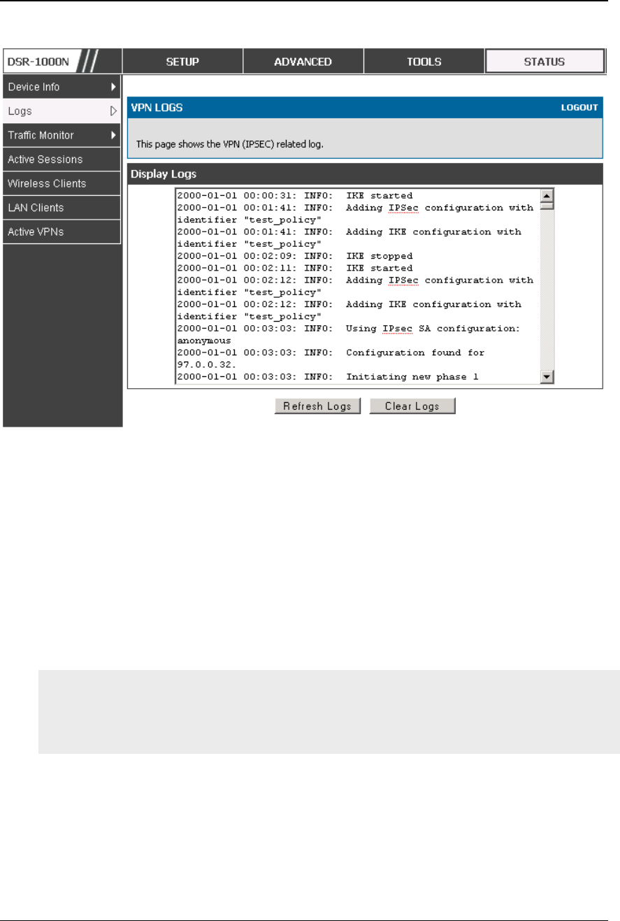
Unified Services Router User Manual
170
Figure 118: VPN logs displaye d i n GUI event viewer
9.5 Backing up and Restoring Configuration
Settings
Tools > System
You can back up the router’s custom configuration settings to restore them to a
different device or the same router after some other changes. During backup, your
settings are saved as a file on your host. You can restore the router's saved settings
from this file as well. This page will also allow you revert to factory default settings
or execute a soft reboot of the router.
IMPORTANT! During a restore operation, do NOT try to go online, turn off the
router, shut down the PC, or do anything else to the router until the operation is
complete. This will take approximately 1 minute. Once the LEDs are turned off,
wait a few more seconds before doing anything with the router.
For backing up configuration or restoring a previously saved configuration, please
follow the steps below:
1. To save a copy of your current settings, click the Backup button in the Save Current
Settings option. The browser initiates an export of the configuration file and prompts to
save the file on your host.
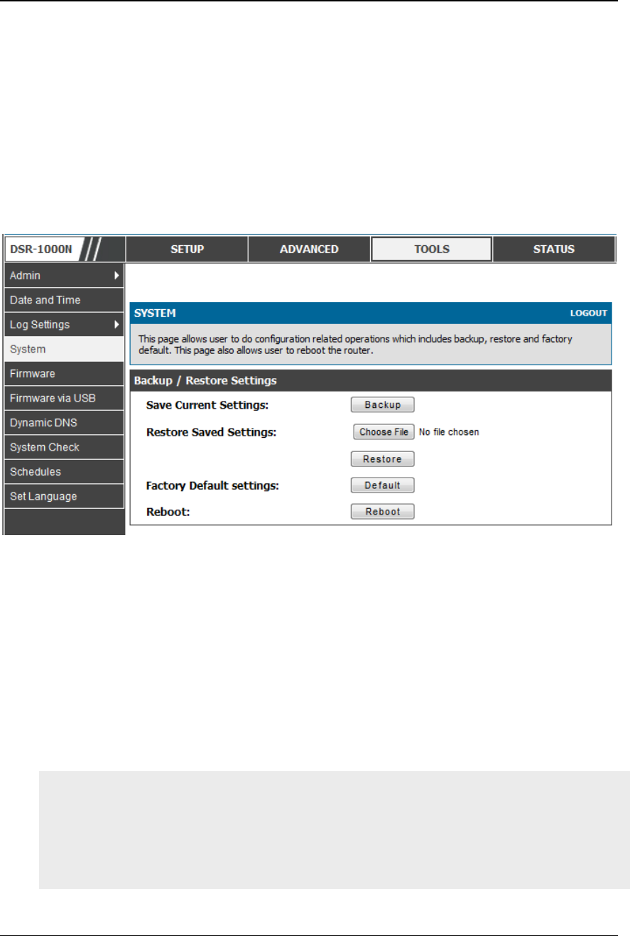
Unified Services Router User Manual
171
2. To restore your saved settings from a backup file, click Browse then locate the file on the
host. After clicking Restore, the router begins importing the file’s saved configuration
settings. After the restore, the router reboots automatically with the restored settings.
3. To erase your current settings and revert to factory default settings, click the Default
button. The router will then restore configuration settings to factory defaults and will
reboot automatically. (See Appendix B for the factory default parameters for the router).
Figure 119: Rest oring configur ation from a saved f ile will result i n the
current configura tion being overwritten and a reboot
9.6 Upgrading Router Firmware
Tools > Firmware
You can upgrade to a newer software version from the Administration web pag e. In
the Firmware Upgrade section, to upgrade your firmware, click Browse, locate and
select the firmware image on your host, and click Upgrade. After the new firmware
image is validated, the new image is written to flash, and the router is automatically
rebooted with the new firmware. The Firmware Information and also the Status >
Device Info > Device Status page will reflect the new firmware version.
IMPORTANT! During firmware upgrade, do NOT try to go online, turn off the
DSR, shut down the PC, or interrupt the process in anyway until the operation is
complete. This should take only a minute or so including the reboot process.
Interrupting the upgrade process at specific points when the flash is being written
to may corrupt the flash memory and render th e router unusable without a low-level
process of restoring the flash firmware (not through the web GUI).

Unified Services Router User Manual
172
Figure 120: Fir mwar e version informatio n and upgrade o ptio n
This router also supports an automated notification to determin e if a newer firmware
version is available for this router. By clicking the Check Now button in the
notification section, the router will check a D-Link server to see if a newer firmware
version for this router is available for download and update the Stat us field below.
IMPORTANT! After firmware 1.04B13, new user database architecture is
introduced. The new user database is easier to setup and more intuitively to use.
When users upgrade DSR’s firmware to 1.04B13 or latter, DSR will automatically
merge users in the old database into the new one. However, all user databases will
be swept away when users downgrade firmware from 1.04B13 to the older one, e.g.
1.03B43. Please keep in mind: backup your user database for further restoring once
you decide to downgrade firmware to the older one.
9.7 Upgrading Router Firmware via USB
Tools > Firmware via USB
This page allows user to upgrade the firmware, backup and restore the settings using a
USB storage key.
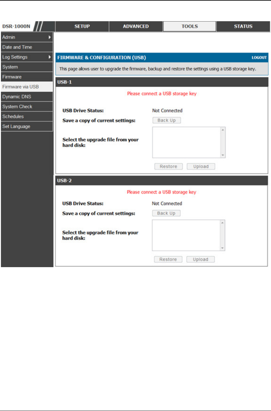
Unified Services Router User Manual
173
Figure 121: Firmware upgrade a nd con figuratio n restore/backup vi a USB
9.8 Dynamic DNS Setup
Tools > Dynamic DNS
Dynamic DNS (DDNS) is an Internet service that allows routers with varying public
IP addresses to be located using Internet domain names. To use DDNS, you must
setup an account with a DDNS provider such as DynDNS.org, D-Link DDNS, or
Oray.net.
Each configured WAN can have a different DDNS service if required. Once
configured, the router will update DDNS services changes in the WAN IP address so
that features that are dependent on acc essing the router’s WAN via FQDN will be
directed to the correct IP address. When you set up an account with a DDNS service,
the host and domain name, username, password and wildcard support will be provided
by the account provider.
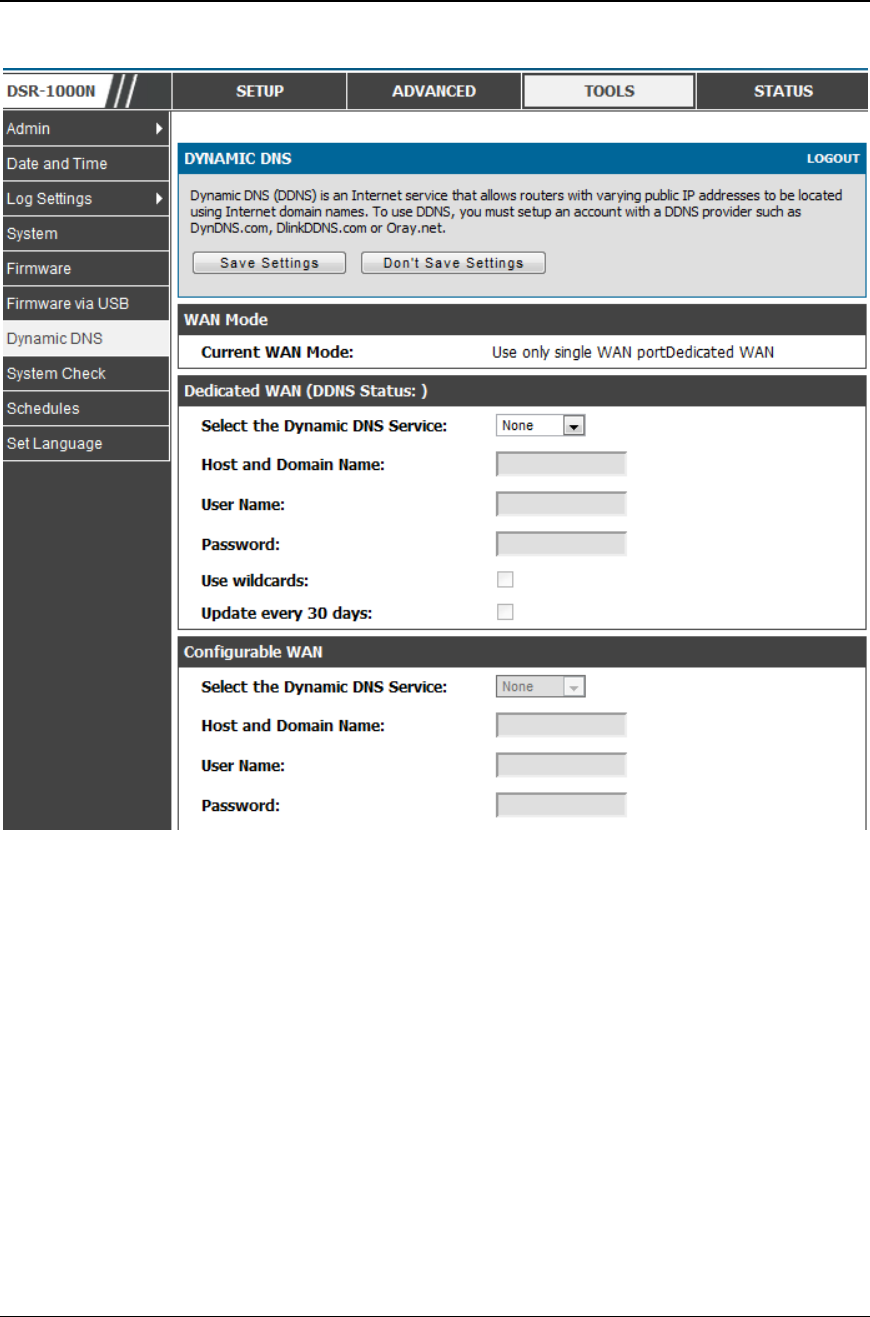
Unified Services Router User Manual
174
Figure 122: Dynamic DNS co nfiguration
9.9 Using Diagnostic Tools
Tools > System Check
The router has built in tools to allow an administrator to evaluate the communication
status and overall network health.
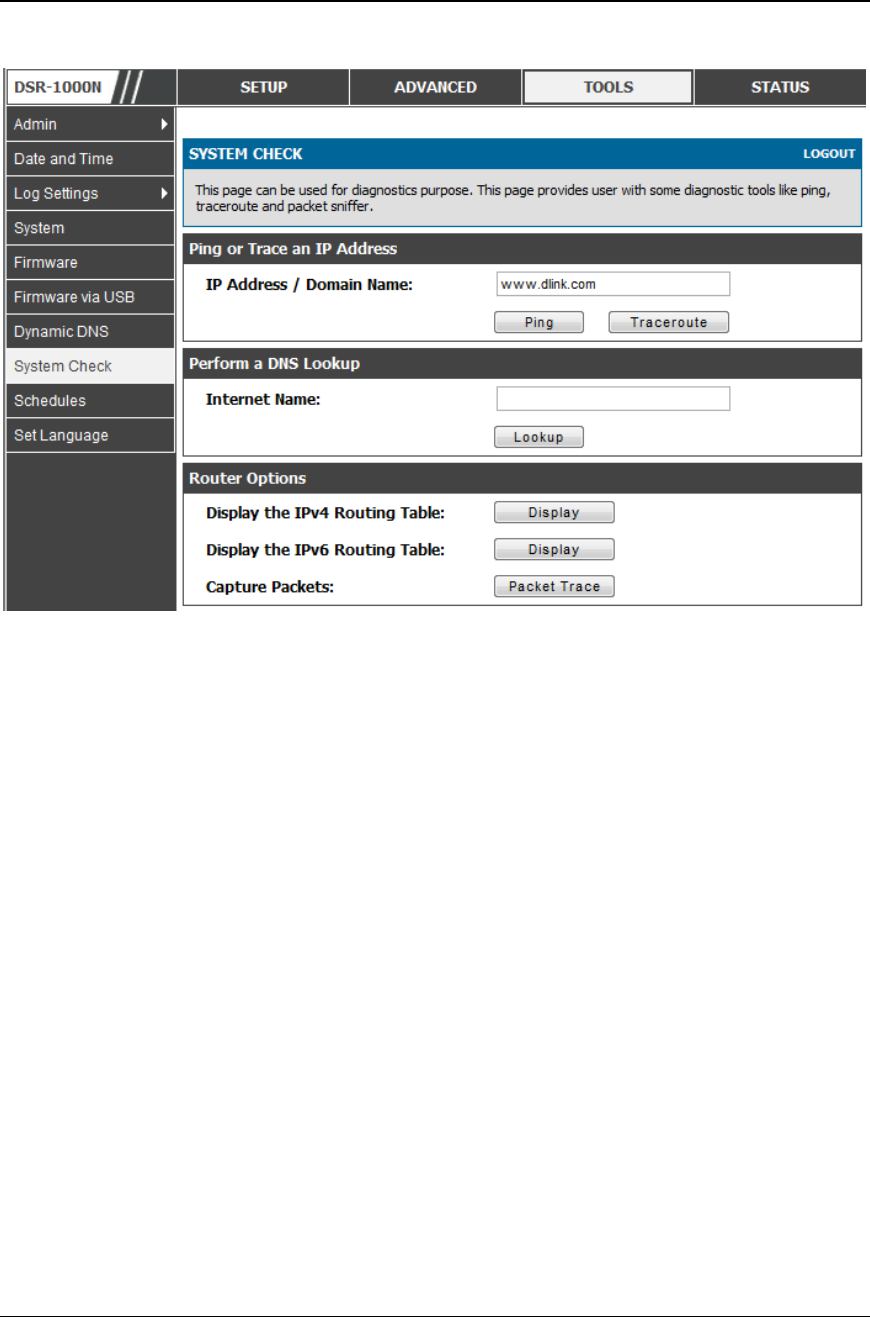
Unified Services Router User Manual
175
Figure 123: Router diagno stics tools available in the GUI
9.9.1 Ping
This utility can be used to test connectivity between this router and another device
on the network connected to this router. Enter an IP address and click PING . The
command output will appear indicating the ICMP echo request status.
9.9.2 Trace Route
This utility will display all the routers present between the destination IP address
and this router. Up to 30 “hops” (intermediate routers) between this router and the
destination will be displayed.
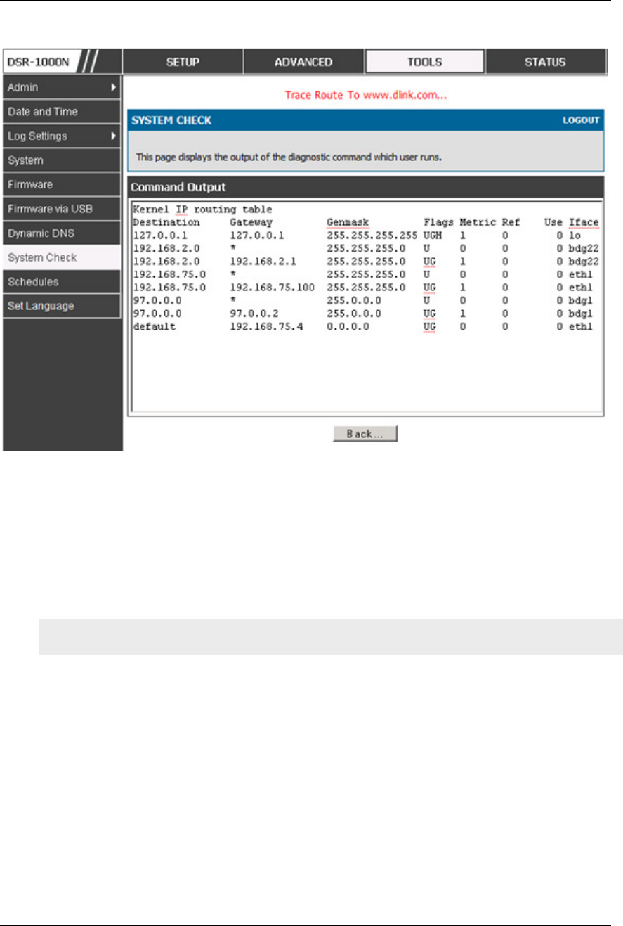
Unified Services Router User Manual
176
Figure 124: Sample trace route output
9.9.3 DNS Lookup
To retrieve the IP address of a Web, FTP, Mail or any other server on the Internet,
type the Internet Name in the text box and click Lookup. If the host or domain entry
exists, you will see a response with the IP address. A message stating “Unknown
Host” indicates that the specified Internet Name does not exist.
This feature assumes there is internet access available on the WAN link(s).
9.9.4 Router Options
The static and dynamic routes configured on this r outer can be shown by clicking
Display for the corresponding routing table. Clicking the Packet Trace button will
allow the router to capture and display traffic through the DSR between the LAN
and WAN interface as well. This information is often very useful in debugging
traffic and routing issues.
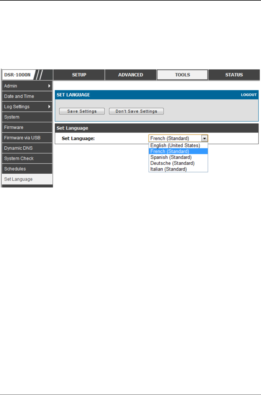
Unified Services Router User Manual
177
9.10 Localization
Tools > Set Language
The router has built in tools to allow change the default language (English) to four
different languages. (French, Deutsche, Spanish and Italian)
Figure 125: L ocali zation

Unified Services Router User Manual
178
Chapter 10. Router Status and
Statistics
10.1 System Overview
The Status page allows you to get a detailed overview of the system configuration.
The settings for the wired and wireless interfaces are displayed in the DSR Status
page, and then the resulting hardware resource and router usage details are
summarized on the router’s Dashboard.
10.1.1 Device Status
Status > Device Info > Device Status
The DSR Status page gives a summary of the router configuration settings
configured in the Setup and Advanced menus. The static hardware serial number and
current firmware version are presented in the General section. The WAN and LAN
interface information shown on this page are based on the administrator
configuration parameters. The radio band and channel settings are presented below
along with all configured and active APs that are enabled on this router.
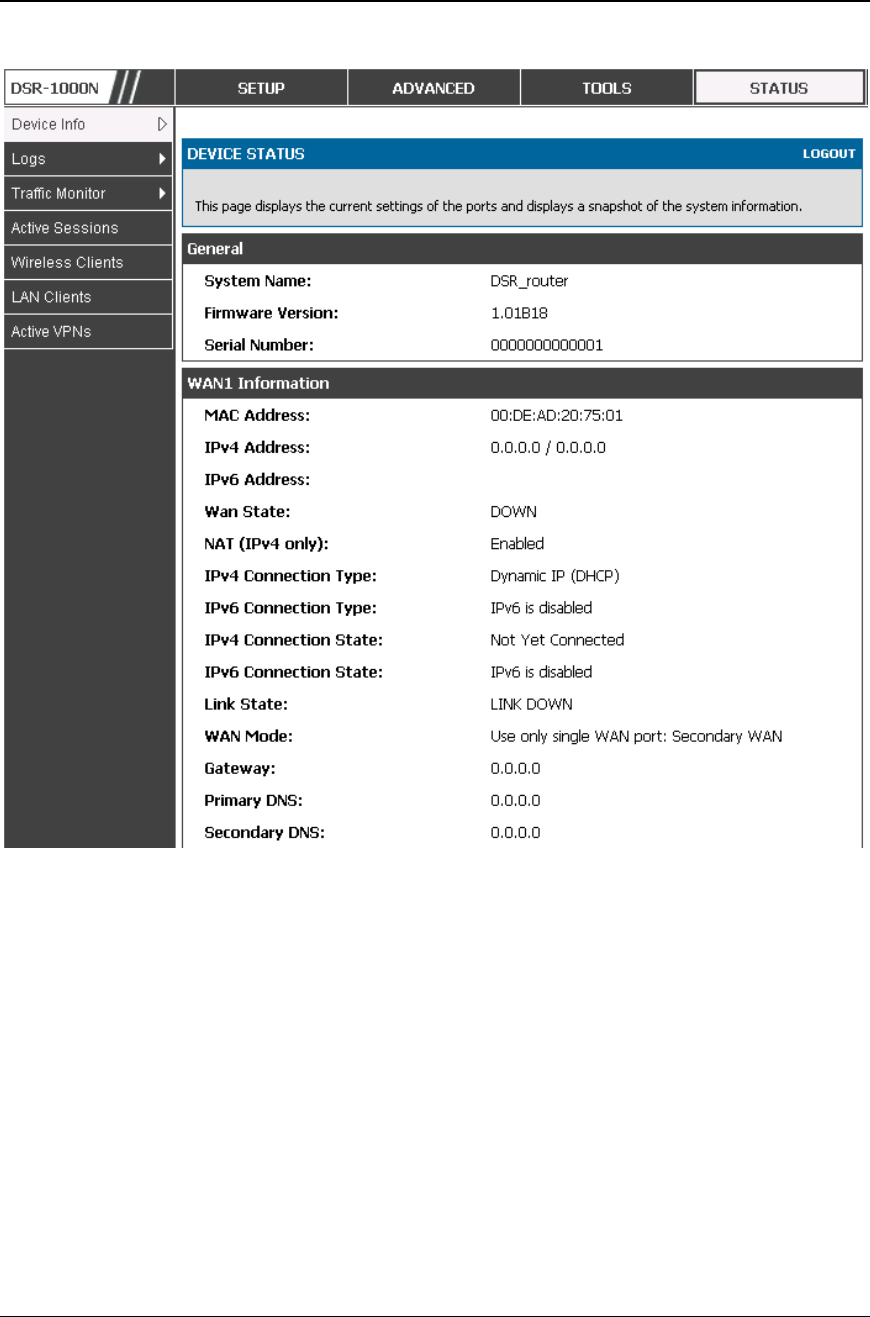
Unified Services Router User Manual
179
Figure 126: Device Status di splay
Unified Services Router User Manual
180
Figure 127: Device Status di splay (continued)
10.1.2 Resource Utilization
Status > Device Info > Dashboard
The Dashboard page presents hardware and usage statistics. The CPU and Memory
utilization is a function of the available hardware and current configuration and
traffic through the router. Interface statistics for the wired connections (LAN,
WAN1, WAN2/DMZ, VLANs) provide indication of packets through and packets
dropped by the interface. Click refresh to have this page retrieve the most current
statistics.
Unified Services Router User Manual
181
Figure 128: Resource Utilization statistics
Unified Services Router User Manual
182
Figure 129: Resource Utilization data (continue d)
Unified Services Router User Manual
183
Figure 130: Resource Utilization data (continue d)
10.2 Traffic Statistics
10.2.1 Wired Port Statistics
Status > Traffic Monitor > Device Statistics
Detailed transmit and receive statistics for each physical port are presented here.
Each interface (WAN1, WAN2/DMZ, LAN, and VLANs) have port specific packet
level information provided for review. Transmitted/received packets, port collisions,
and the cumulating bytes/sec for transmit/receive directions are provided for each
interface along with the port up time. If you suspect issues with any of the wired
ports, this table will help diagnose uptime or transmit level issues with the port.
The statistics table has auto-refresh control which allows display of the most current
port level data at each page refresh. The default auto-refresh for this page is 10
seconds.
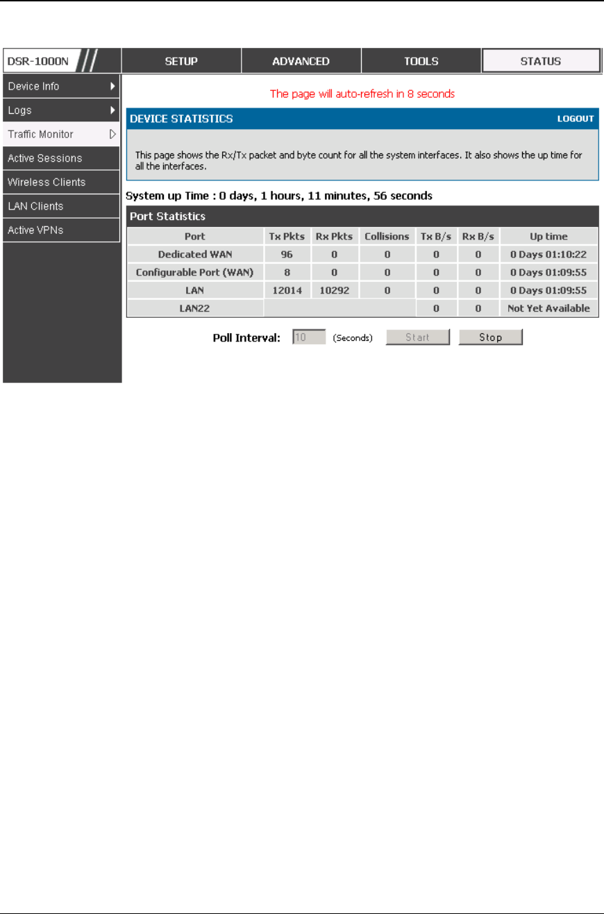
Unified Services Router User Manual
184
Figure 131: P hysical port statistics
10.2.2 Wireless Statistics
Status > Traffic Monitor > Wireless Statistics
The Wireless Statistics tab displays the incrementing traffic statistics for each
enabled access point. This page will give a snapshot of how much traffic is being
transmitted over each wireless link. If you suspect that a radio or VAP may be
down, the details on this page would confirm if traffic is being sent and received
through the VAP.
The clients connected to a particular AP can be viewed by using the Status Button
on the list of APs in the Setup > Wireless > Access Points page. Traffic statistics
are shown for that individual AP, as compared to the summary stats for each AP on
this Statistics page. The poll interval (the refresh rate for the statistics) can be
modified to view more frequent traffic and collision statistics.
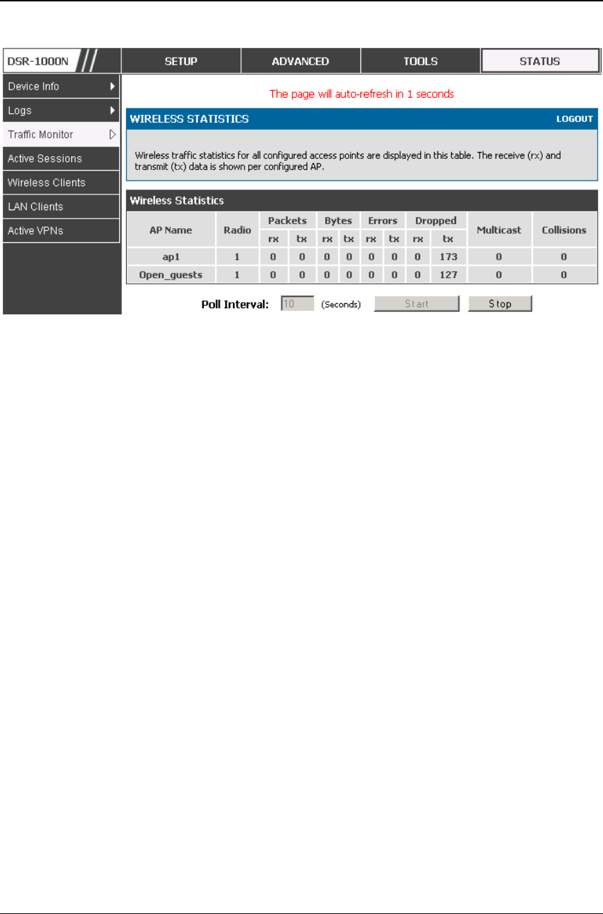
Unified Services Router User Manual
185
Figure 132: AP specific statistics
10.3 Active Connections
10.3.1 Sessions through the Router
Status > Active Sessions
This table lists the active internet sessions through the router’s firewall. The
session’s protocol, state, local and remote IP addresses are shown.
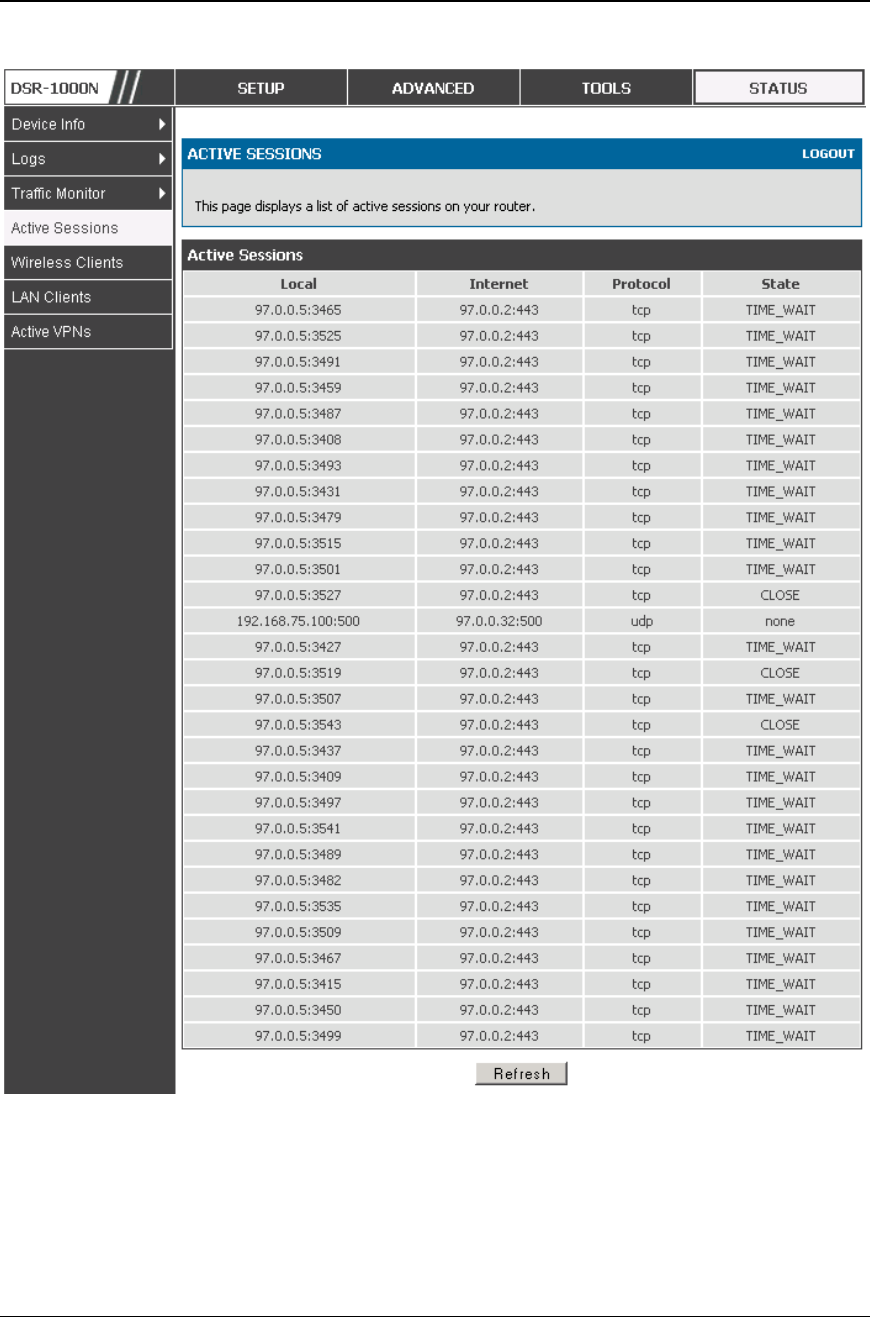
Unified Services Router User Manual
186
Figure 133: List of current Active Firewall Sessio ns
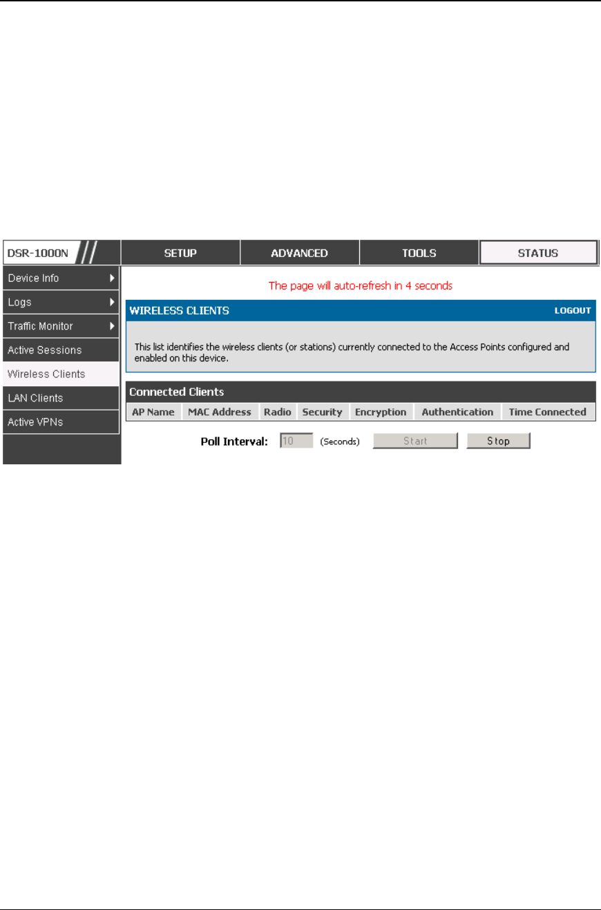
Unified Services Router User Manual
187
10.3.2 Wireless Clients
Status > Wireless Clients
The clients connected to a particular AP can be viewed on this page. Connected
clients are sorted by the MAC address and indicate the security parameters used by
the wireless link, as well as the time connected to the corresponding AP.
The statistics table has auto-refresh control which allows display of the most current
port level data at each page refresh. The default auto-refresh for this page is 10
seconds.
Figure 134: List of connected 802.11 clients per AP
10.3.3 LAN Clients
Status > LAN Clients
The LAN clients to the router are identified by an ARP scan through the LAN
switch. The NetBios name (if available), IP address and MAC address of discovered
LAN hosts are displayed.
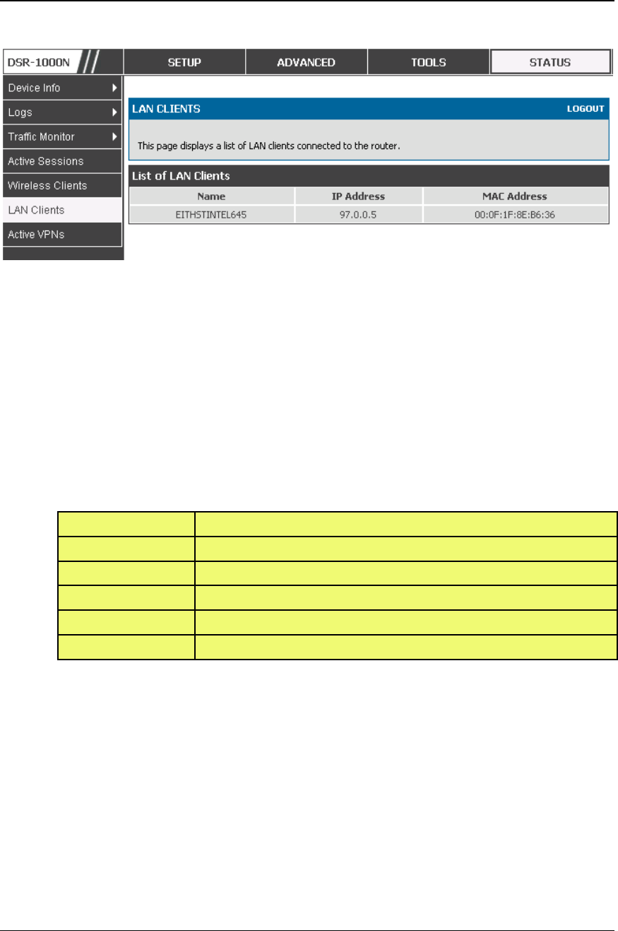
Unified Services Router User Manual
188
Figure 135: List of LAN hosts
10.3.4 Active VPN Tunnels
Status > Active VPNs
You can view and change the status (connect or drop) of the router’s IPsec security
associations. Here, the active IPsec SAs (security associations) are listed along with
the traffic details and tunnel state. The traffic is a cumulative measure of
transmitted/received packets since the tunnel was esta blished.
If a VPN policy state is “IPsec SA Not Established”, it can be enabled by clicking
the Connect button of the corresponding policy. The Active IPsec SAs table displays
a list of active IPsec SAs. Table fields are as follows.
Field
Description
Policy Name
IKE or VPN policy associated with this SA.
Endpoint
IP address of the remote VPN gateway or client.
Tx (KB)
Kilobytes of data transmitted over this SA.
Tx (Packets)
Number of IP packets transmitted over this SA.
State
Status of the SA for IKE policies: Not Connected or IPsec SA Established.
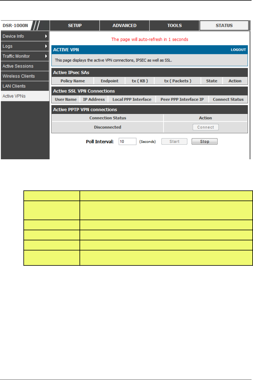
Unified Services Router User Manual
189
Figure 136: List of current Active VPN Sessions
All active SSL VPN connections, both for VPN tunnel and VPN Port forwarding, are
displayed on this page as well. Table fields are as follows.
Field
Description
User Name
The SSL VPN user that has an active tunnel or port forwarding session to this
router.
IP Address
IP address of the remote VPN client.
Local PPP Interface
The interface (WAN1 or WAN2) through which the session is active.
Peer PPP Interface IP
The assigned IP address of the virtual network adapter.
Connect Status
Status of the SSL connection between this router and the remote VPN client: Not
Connected or Connected.

Unified Services Router User Manual
190
Chapter 11. Trouble Shooting
11.1 Internet connection
Symptom: You cannot access the router’s web-configuration interface from a PC on
your LAN.
Recommended action:
1. Check the Ethernet connection between the PC and the router.
2. Ensure that your PC’s IP address is on the same subnet as the router. If you are using the
recommended addressing scheme, your PC’s address should be in the range 192.168.10.2
to 192.168.10.254.
3. Check your PC’s IP address. If the PC cannot reach a DHCP server, some versions of
Windows and Mac OS generate and assign an IP address. These auto-generated addresses
are in the range 169.254.x.x. If your IP address is in this range, check the connection from
the PC to the firewall and reboot your PC.
4. If your router’s IP address has changed and you don’t know what it is, reset the router
configuration to factory defaults (this sets the firewall’s IP address to 192.168.10.1).
5. If you do not want to reset to factory default settings and lose your configuration, reboot
the router and use a packet sniffer (such as Ethereal™) to capture packets sent during the
reboot. Look at the Address Resolution Protocol (ARP) packets to locate the router’s LAN
interface address.
6. Launch your browser and ensure that Java, JavaScript, or ActiveX is enabled. If you are
using Internet Explorer, click Refresh to ensure that the Java applet is loaded. Close the
browser and launch it again.
7. Ensure that you are using the correct login information. The factory default login name is
admin and the password is password. Ensure that CAPS LOCK is off when entering this
information.
Symptom: Router does not save configuration changes.
Recommended action:
1. When entering configuration settings, click Apply before moving to another menu or tab;
otherwise your changes are lost.
2. Click Refresh or Reload in the browser. Your changes may have been made, but the
browser may be caching the old configuration.

Unified Services Router User Manual
191
Symptom: Router cannot access the Internet.
Possible cause: If you use dynamic IP addresses, your router may not have requested
an IP address from the ISP.
Recommended action:
1. Launch your browser and go to an external site such as www.google.com.
2. Access the firewall’s configuration main menu at http://192.168.10.1.
3. Select Monitoring > Router Status.
4. Ensure that an IP address is shown for the WAN port. If 0.0.0.0 is shown, your firewall
has not obtained an IP address from your ISP. See the next symptom.
Symptom: Router cannot obtain an IP address from the ISP.
Recommended action:
1. Turn off power to the cable or DSL modem.
2. Turn off the router.
3. Wait 5 minutes, and then reapply power to the cable or DSL modem.
4. When the modem LEDs indicate that it has resynchronized with the ISP, reapply power to
the router. If the router still cannot obtain an ISP address, see the next symptom.
Symptom: Router still cannot obtain an IP address from the ISP.
Recommended action:
1. Ask your ISP if it requires a login program — PPP over Ethernet (PPPoE) or some other
type of login.
2. If yes, verify that your configured login name and password are correct.
3. Ask your ISP if it checks for your PC's hostname.
4. If yes, select Network Configuration > WAN Settings > Ethernet ISP
Settings and set the account name to the PC hostname of your ISP account.
5. Ask your ISP if it allows only one Ethernet MAC address to connect to the Internet, and
therefore checks for your PC’s MAC address.
6. If yes, inform your ISP that you have bought a new network device, and ask them to use
the firewall’s MAC address.
7. Alternatively, select Network Configuration > WAN Settings > Ethernet ISP
Settings and configure your router to spoof your PC’s MAC address.

Unified Services Router User Manual
192
Symptom: Router can obtain an IP address, but PC is unable to load Internet pages.
Recommended action:
1. Ask your ISP for the addresses of its designated Domain Name System (DNS) servers.
Configure your PC to recognize those addresses. For details, see your operating system
documentation.
2. On your PC, configure the router to be its TCP/IP gateway.
11.2 Date and time
Symptom: Date shown is January 1, 1970.
Possible cause: The router has not yet successfully reached a network time server
(NTS).
Recommended action:
1. If you have just configured the router, wait at least 5 minutes, select Administration >
Time Zone, and recheck the date and time.
2. Verify your Internet access settings.
Symptom: Time is off by one hour.
Possible cause: The router does not automatically adjust for Dayli ght Savings Time.
Recommended action:
1. Select Administration > Time Zone and view the current date and time settings.
2. Click to check or uncheck “Automatically adjust for Daylight Savings Time”, then click
Apply.
11.3 Pinging to Test LAN Connectivity
Most TCP/IP terminal devices and firewalls contain a ping utility that sends an ICMP
echo-request packet to the designated device. The DSR responds with an echo reply.
Troubleshooting a TCP/IP network is made very easy by using the ping utility in your
PC or workstation.
11.3.1 Testing the LAN path from your PC to your
router
1. From the PC’s Windows toolbar, select Start > Run.
2. Type ping <IP_address> where <IP_address> is the router’s IP address. Example: ping
192.168.10.1.
3. Click OK.

Unified Services Router User Manual
193
4. Observe the display:
If the path is working, you see this message sequence:
Pinging <IP address> with 32 bytes of data
Reply from <IP address>: bytes=32 time=NN ms TTL=xxx
If the path is not working, you see this message sequence:
Pinging <IP address> with 32 bytes of data
Request timed out
5. If the path is not working, Test the physical connections between PC and router
If the LAN port LED is off, go to the “LED displays” section on page B -
1 and follow instructions for “LAN or Internet port LEDs are not lit.”
Verify that the corresponding link LEDs are lit for your network
interface card and for any hub ports that are connected to your
workstation and firewall.
6. If the path is still not up, test the network configuration:
Verify that the Ethernet card driver software and TCP/IP software are
installed and configured on the PC.
Verify that the IP address for the router and PC are correct and on the
same subnet.
11.3.2 Testing the LAN path from your PC to a remote
device
1. From the PC’s Windows toolbar, select Start > Run.
2. Type ping -n 10 <IP_address> where -n 10 specifies a maximum of 10 tries and <IP
address> is the IP address of a remote device such as your ISP’s DNS server. Example:
ping -n 10 10.1.1.1.
3. Click OK and then observe the display (see the previous procedure).
4. If the path is not working, do the following:
Check that the PC has the IP address of your firewall listed as the
default gateway. (If the IP configuration of your PC is assigned by
DHCP, this information is not visible in your PC’s Network Control
Panel.)

Unified Services Router User Manual
194
Verify that the network (subnet) address of your PC is different from the
network address of the remote device.
Verify that the cable or DSL modem is connected and functioning.
Ask your ISP if it assigned a hostname to your PC.
If yes, select Network Configuration > WAN Settings > Ethernet I SP
Settings and enter that hostname as the ISP account name.
Ask your ISP if it rejects the Ethernet MAC addresses of all but one of
your PCs.
Many broadband ISPs restrict access by allowing traffic from the MAC address of
only your broadband modem; but so me ISPs additionally restrict access to the MAC
address of just a single PC connected to that modem. If this is the case, configure
your firewall to clone or spoof the MAC address from the authorized PC.
11.4 Restoring factory-default configuration
settings
To restore factory-default configuration settings, do either of the following:
1. Do you know the account password and IP address?
If yes, select Administration > Settings Backup & Upgrade and
click default.
If no, do the following:
On the rear panel of the router, press and hold the Reset button about 10 seconds,
until the test LED lights and then blinks.
Release the button and wait for the router to reboot.
2. If the router does not restart automatically; manually restart it to make the default settings
effective.
3. After a restore to factory defaults —whether initiated from the configuration interface or
the Reset button — the following settings apply:
LAN IP address: 192.168.10.1
Username: admin
Password: admin
DHCP server on LAN: enabled
WAN port configuration: Get configuration via DHCP

Chapter 12. Credits
Microsoft, Windows are registered trademarks of Microsoft Corp.
Linux is a registered trademark of Linus Torvalds.
UNIX is a registered trademark of The Open Group.

Unified Services Router User Manual
196
Appendix A. Glossary
ARP
Address Resolution Protocol. Broadcast protocol for mapping IP addresses to MAC addresses.
CHAP
Challenge-Handshake Authentication Protocol. Protocol for authenticating users to an ISP.
DDNS
Dynamic DNS. System for updating domain names in real time. Allows a domain name to be
assigned to a device with a dynamic IP address.
DHCP
Dynamic Host Configuration Protocol. Protocol for allocating IP addresses dynamically so that
addresses can be reused when hosts no longer need them.
DNS
Domain Name System. Mechanism for translating H.323 IDs, URLs, or e-mail IDs into IP
addresses. Also used to assist in locating remote gatekeepers and to map IP addresses to
hostnames of administrative domains.
FQDN
Fully qualified domain name. Complete domain name, including the host portion. Example:
serverA.companyA.com.
FTP
File Transfer Protocol. Protocol for transferring files between network nodes.
HTTP
Hypertext Transfer Protocol. Protocol used by web browsers and web servers to transfer files.
IKE
Internet Key Exchange. Mode for securely exchanging encryption keys in ISAKMP as part of
building a VPN tunnel.
IPsec
IP security. Suite of protocols for securing VPN tunnels by authenticating or encrypting IP
packets in a data stream. IPsec operates in either transport mode (encrypts payload but not
packet headers) or tunnel mode (encrypts both payload and packet headers).
ISAKMP
Internet Key Exchange Security Protocol. Protocol for establishing security associations and
cryptographic keys on the Internet.
ISP
Internet service provider.
MAC Address
Media-access-control address. Unique physical-address identifier attached to a network
adapter.
MTU
Maximum transmission unit. Size, in bytes, of the largest packet that can be passed on. The
MTU for Ethernet is a 1500-byte packet.
NAT
Network Address Translation. Process of rewriting IP addresses as a packet passes through a
router or firewall. NAT enables multiple hosts on a LAN to access the Internet using the single
NetBIOS
Microsoft Windows protocol for file sharing, printer sharing, messaging, authentication, and
name resolution.
NTP
Network Time Protocol. Protocol for synchronizing a router to a single clock on the network,
known as the clock master.
PAP
Password Authentication Protocol. Protocol for authenticating users to a remote access server
or ISP.

Unified Services Router User Manual
197
PPPoE
Point-to-Point Protocol over Ethernet. Protocol for connecting a network of hosts to an ISP
without the ISP having to manage the allocation of IP addresses.
PPTP
Point-to-Point Tunneling Protocol. Protocol for creation of VPNs for the secure transfer of data
from remote clients to private servers over the Internet.
RADIUS
Remote Authentication Dial-In User Service. Protocol for remote user authentication and
accounting. Provides centralized management of usernames and passwords.
RSA
Rivest-Shamir-Adleman. Public key encryption algorithm.
TCP
Transmission Control Protocol. Protocol for transmitting data over the Internet with guaranteed
reliability and in-order delivery.
UDP
User Data Protocol. Protocol for transmitting data over the Internet quickly but with no
guarantee of reliability or in-order delivery.
VPN
Virtual private network. Network that enables IP traffic to travel securely over a public TCP/IP
network by encrypting all traffic from one network to another. Uses tunneling to encrypt all
information at the IP level.
WINS
Windows Internet Name Service. Service for name resolution. Allows clients on different IP
subnets to dynamically resolve addresses, register themselves, and browse the network without
sending broadcasts.
XAUTH
IKE Extended Authentication. Method, based on the IKE protocol, for authenticating not just
devices (which IKE authenticates) but also users. User authentication is performed after device
authentication and before IPsec negotiation.

Appendix B. Factory Default Settings
Feature
Description
Default Setting
Device login
User login URL
http://192.168.10.1
User name (case sensitive)
admin
Login password (case sensitive)
admin
Internet
Connection
WAN MAC address
Use default address
WAN MTU size
1500
Port speed
Autosense
Local area network
(LAN)
IP address
192.168.10.1
IPv4 subnet mask
255.255.255.0
RIP direction
None
RIP version
Disabled
RIP authentication
Disabled
DHCP server
Enabled
DHCP starting IP address
192.168.10.2
DHCP ending IP address
192.168.10.100
Time zone
GMT
Time zone adjusted for Daylight Saving Time
Disabled
SNMP
Disabled
Remote management
Disabled
Firewall
Inbound communications from the Internet
Disabled (except traffic on port
80, the HTTP port)
Outbound communications to the Internet
Enabled (all)
Source MAC filtering
Disabled
Stealth mode
Enabled

Unified Services Router User Manual
200
Appendix C. Standard Services
Available for Port Forwarding
& Firewall Configuration
ANY
AIM
BGP
BOOTP_CLIENT
BOOTP_SERVER
CU-SEEME:UDP
CU-SEEME:TCP
DNS:UDP
DNS:TCP
FINGER
FTP
HTTP
HTTPS
ICMP-TYPE-3
ICMP-TYPE-4
ICMP-TYPE-5
ICMP-TYPE-6
ICMP-TYPE-7
ICMP-TYPE-8
ICMP-TYPE-9
ICMP-TYPE-10
ICMP-TYPE-11
ICMP-TYPE-13
ICQ
IMAP2
IMAP3
IRC
NEWS
NFS
NNTP
PING
POP3
PPTP
RCMD
REAL-AUDIO
REXEC
RLOGIN
RTELNET
RTSP:TCP
RTSP:UDP
SFTP
SMTP
SNMP:TCP
SNMP:UDP
SNMP-TRAPS:TCP
SNMP-TRAPS:UDP
SQL-NET
SSH:TCP
SSH:UDP
STRMWORKS
TACACS
TELNET
TFTP
VDOLIVE

Unified Services Router User Manual
201
Appendix D. Log Output Reference
Facility: System (Networking)
Log Message
Severity
Log Message
Severity
DBUpdate event: Table: %s opCode:%d
rowId:%d
DEBUG
BridgeConfig: too few arguments to
command %s
ERROR
networkIntable.txt not found
DEBUG
BridgeConfig: too few arguments to
command %s
ERROR
sqlite3QueryResGet failed
DEBUG
sqlite3QueryResGet failed.Query:%s
ERROR
Interface is already deleted in bridge
DEBUG
ddnsDisable failed
ERROR
removing %s from bridge %s... %s
DEBUG
sqlite3QueryResGet failed.Query:%s
ERROR
adding %s to bridge %s... %s
DEBUG
sqlite3QueryResGet failed.Query:%s
ERROR
stopping bridge...
DEBUG
ddnsDisable failed
ERROR
stopping bridge...
DEBUG
failed to call ddns enable
ERROR
stopping bridge...
DEBUG
ddnsDisable failed
ERROR
%s:DBUpdate event: Table: %s
opCode:%d rowId:%d
DEBUG
sqlite3QueryResGet failed.Query:%s
ERROR
Wan is not up
DEBUG
Error in executing DB update handler
ERROR
%s:DBUpdate event: Table: %s
opCode:%d rowId:%d
DEBUG
sqlite3QueryResGet failed.Query:%s
ERROR
doDNS:failed
DEBUG
Illegal invocation of ddnsView (%s)
ERROR
doDNS:failed
DEBUG
sqlite3QueryResGet failed.Query:%s
ERROR
doDNS:Result = FAILED
DEBUG
sqlite3QueryResGet failed.Query:%s
ERROR
doDNS:Result SUCCESS
DEBUG
ddns: SQL error: %s
ERROR
Write Old Entry: %s %s %s: to %s
DEBUG
Illegal operation interface got deleted
ERROR
Write New Entry: %s %s #%s : to %s
DEBUG
sqlite3QueryResGet failed.Query:%s
ERROR
Write Old Entry: %s %s %s: to %s
DEBUG
sqlite3QueryResGet failed.Query:%s
ERROR
Write New Entry: %s %s #%s : to %s
DEBUG
sqlite3QueryResGet failed.Query:%s
ERROR
ifStaticMgmtDBUpdateHandler: returning
with "
DEBUG
ddnsDisable failed
ERROR
nimfLinkStatusGet: buffer: \
DEBUG
ddns: SQL error: %s
ERROR
nimfLinkStatusGetErr: returning with
status: %d
DEBUG
Failed to call ddns enable
ERROR
nimfAdvOptSetWrap: current Mac
Option: %d
DEBUG
ddns: SQL error: %s
ERROR
nimfAdvOptSetWrap: current Port Speed
Option: %d
DEBUG
sqlite3QueryResGet failed.Query:%s
ERROR
nimfAdvOptSetWrap: current Mtu Option:
%d
DEBUG
Failed to call ddns enable
ERROR
nimfAdvOptSetWrap: looks like we are
reconnecting. "
DEBUG
ddns: SQL error: %s
ERROR
nimfAdvOptSetWrap: Mtu Size: %d
DEBUG
ddnsDisable failed
ERROR
nimfAdvOptSetWrap: NIMF table is %s
DEBUG
ddns: SQL error: %s
ERROR
nimfAdvOptSetWrap:WAN_MODE
TRIGGER
DEBUG
sqlite3QueryResGet failed.Query:%s
ERROR
nimfAdvOptSetWrap: MTU: %d
DEBUG
Failed to call ddns enable
ERROR
nimfAdvOptSetWrap: MacAddress: %s
DEBUG
ddns: SQL error: %s
ERROR
nimfAdvOptSetWrap: old Mtu Flag: %d
DEBUG
ddnsDisable failed
ERROR

Unified Services Router User Manual
202
nimfAdvOptSetWrap: user has changed
MTU option
DEBUG
ddns: SQL error: %s
ERROR
nimfAdvOptSetWrap: MTU: %d
DEBUG
sqlite3QueryResGet failed.Query:%s
ERROR
nimfAdvOptSetWrap: old MTU size: %d
DEBUG
sqlite3QueryResGet failed.Query:%s
ERROR
nimfAdvOptSetWrap: old Port Speed
Option: %d
DEBUG
ddnsDisable failed
ERROR
nimfAdvOptSetWrap: old Mac Address
Option: %d
DEBUG
ddns: SQL error: %s
ERROR
nimfAdvOptSetWrap: MacAddress: %s
DEBUG
sqlite3QueryResGet failed.Query:%s
ERROR
Setting LED [%d]:[%d] For %s
DEBUG
sqlite3QueryResGet failed.Query:%s
ERROR
l2tpEnable: command string: %s
DEBUG
ddnsDisable failed
ERROR
nimfAdvOptSetWrap: handling reboot
scenario
DEBUG
failed to call ddns enable
ERROR
nimfAdvOptSetWrap: INDICATOR = %d
DEBUG
ddns: SQL error: %s
ERROR
nimfAdvOptSetWrap: UpdateFlag: %d
DEBUG
ddnsDisable failed
ERROR
nimfAdvOptSetWrap: returning with
status: %s
DEBUG
sqlite3QueryResGet failed.Query:%s
ERROR
nimfGetUpdateMacFlag: MacTable Flag
is: %d
DEBUG
Error in executing DB update handler
ERROR
nimfMacGet: Mac Option changed
DEBUG
Failed to open the resolv.conf file.
Exiting./n
ERROR
nimfMacGet: Update Flag: %d
DEBUG
Could not write to the resolv.conf file.
Exiting.
ERROR
nimfMacGet: MacAddress: %s
DEBUG
Error opening the lanUptime File
ERROR
nimfMacGet: MacAddress: %s
DEBUG
Error Opening the lanUptime File.
ERROR
nimfMacGet: MacAddress: %s
DEBUG
failed to open %s
ERROR
nimfMacGet: MacAddress: %s
DEBUG
failed to open %s
ERROR
nimfMacGet: MacAddress: %s
DEBUG
failed to query networkInterface table
ERROR
nimfMacGet:Mac option Not changed \
DEBUG
failed to query networkInterface table
ERROR
nimfMacGet: MacAddress: %s
DEBUG
sqlite3QueryResGet failed.Query:%s
ERROR
nimfMacGet: MacAddress: %s
DEBUG
failed to enable IPv6 forwarding
ERROR
nimfMacGet: MacAddress: %s
DEBUG
failed to set capabilities on the "
ERROR
nimfMacGet: returning with status: %s
DEBUG
failed to enable IPv6 forwarding
ERROR
Now in enableing LanBridge function
DEBUG
failed to set capabilities on the "
ERROR
sucessfully executed the command %s
DEBUG
failed to disable IPv6 forwarding
ERROR
Now in disableing LanBridge function
DEBUG
failed to set capabilities on the "
ERROR
sucessfully executed the command %s
DEBUG
failed to open %s
ERROR
configPortTblHandler:Now we are in
Sqlite Update "
DEBUG
Could not create ISATAP Tunnel
ERROR
The Old Configuration of ConfiPort
was:%s
DEBUG
Could not destroy ISATAP Tunnel
ERROR
The New Configuration of ConfiPort
was:%s
DEBUG
Could not configure ISATAP Tunnel
ERROR
The user has deselected the
configurable port
DEBUG
Could not de-configure ISATAP
Tunnel
ERROR
failed query %s
DEBUG
nimfStatusUpdate: updating
NimfStatus failed
ERROR
failed query %s
DEBUG
nimfStatusUpdate: updating
NimfStatus failed
ERROR
failed query %s
DEBUG
nimfLinkStatusGet: determinig link's
status failed
ERROR
%s:DBUpdate event: Table: %s
opCode:%d rowId:%d
DEBUG
nimfLinkStatusGet: opening status file
failed
ERROR

Unified Services Router User Manual
203
%s:DBUpdate event: Table: %s
opCode:%d rowId:%d
DEBUG
Failed to commit
ERROR
%s:%d SIP ENABLE: %s
DEBUG
ifStatusDBUpdate: Failed to begin "
ERROR
sipTblHandler:failed to update ifStatic
DEBUG
%s: SQL error: %s
ERROR
sipTblHandler:failed to update Configport
DEBUG
%s: Failed to commit "
ERROR
%s:%d SIP DISABLE: %s
DEBUG
nimfNetIfaceTblHandler: unable to get
LedPinId
ERROR
%s:%d SIP SET CONF: %s
DEBUG
nimfNetIfaceTblHandler: unable to get
LedPinId
ERROR
Failed to open %s: %s
DEBUG
nimfNetIfaceTblHandler: unable to get
LedPinId
ERROR
Failed to start sipalg
DEBUG
%s: unable to kill dhclient
ERROR
Failed to stop sipalg
DEBUG
nimfAdvOptSetWrap: unable to get
current Mac Option
ERROR
Failed to get config info
DEBUG
nimfAdvOptSetWrap: unable to get
current Port "
ERROR
Network Mask: 0x%x
DEBUG
nimfAdvOptSetWrap: unable to get
current MTU Option
ERROR
RTP DSCP Value: 0x%x
DEBUG
nimfAdvOptSetWrap: error getting
Mac Address from "
ERROR
Need more arguments
DEBUG
nimfAdvOptSetWrap: unable to get
the MTU
ERROR
Invalid lanaddr
DEBUG
nimfAdvOptSetWrap: error setting
interface advanced "
ERROR
Invalid lanmask
DEBUG
nimfAdvOptSetWrap: error getting
MTU size
ERROR
Invalid option
DEBUG
nimfAdvOptSetWrap: unable to get
Mac Address
ERROR
Failed to set config info
DEBUG
nimfAdvOptSetWrap: error setting
interface advanced "
ERROR
Unknown option
DEBUG
nimfAdvOptSetWrap: failed to get old
connectiontype
ERROR
sshdTblHandler
DEBUG
nimfAdvOptSetWrap: old connection
type is: %s
ERROR
pPort: %s
DEBUG
nimfAdvOptSetWrap: failed to get old
MTU Option
ERROR
pProtocol: %s
DEBUG
nimfAdvOptSetWrap: error getting
MTU size
ERROR
pListerAddr: %s
DEBUG
nimfOldFieldValueGet: failed to get
old "
ERROR
pKeyBits: %s
DEBUG
nimfOldFieldValueGet: user has
changed MTU size
ERROR
pRootEnable: %s
DEBUG
nimfAdvOptSetWrap: failed to get old
Port Speed "
ERROR
pRsaEnable: %s
DEBUG
nimfAdvOptSetWrap: user has
changed Port Speed
ERROR
pDsaEnable: %s
DEBUG
nimfAdvOptSetWrap: failed to get old
Mac Address "
ERROR
pPassEnable: %s
DEBUG
nimfAdvOptSetWrap: user has
changed Mac Address "
ERROR
pEmptyPassEnable: %s
DEBUG
nimfAdvOptSetWrap: unable to get
Mac Address
ERROR
pSftpEnable: %s
DEBUG
nimfAdvOptSetWrap:Failed to RESET
the flag
ERROR
pScpEnable: %s
DEBUG
nimfAdvOptSetWrap: setting
advanced options failed
ERROR
pSshdEnable: %s
DEBUG
nimfAdvOptSetWrap: interface
advanced options applied
ERROR

Unified Services Router User Manual
204
pPrivSep: %s
DEBUG
nimfGetUpdateMacFlag: unable to get
Flag from MacTable
ERROR
%s:DBUpdate event: Table: %s
opCode:%d rowId:%d
DEBUG
nimfMacGet: Updating MAC address
failed
ERROR
Re-Starting sshd daemon....
DEBUG
sqlite3QueryResGet failed.Query:%s
ERROR
sshd re-started successfully.
DEBUG
error executing the command %s
ERROR
sshd stopped .
DEBUG
error executing the command %s
ERROR
failed query %s
DEBUG
error executing the command %s
ERROR
vlan disabled, not applying vlan
configuration..
DEBUG
disableLan function is failed to disable
ConfigPort"
ERROR
failed query %s
DEBUG
sqlite3QueryResGet failed.Query:%s
ERROR
failed query %s
DEBUG
sqlite3QueryResGet failed.Query:%s
ERROR
no ports present in this vlanId %d
DEBUG
Unable to Disable configurable port
from
ERROR
failed query %s
DEBUG
configPortTblHandler has failed
ERROR
vlan disabled, not applying vlan
configuration..
DEBUG
sqlite3QueryResGet failed.Query:%s
ERROR
disabling vlan
DEBUG
Error in executing DB update handler
ERROR
enabling vlan
DEBUG
sqlite3QueryResGet failed
ERROR
vlan disabled, not applying vlan
configuration..
DEBUG
Failed to execute switchConfig for
port\
ERROR
no ports present in this vlanId %d
DEBUG
Failed to execute switchConfig for
port enable
ERROR
failed query %s
DEBUG
Failed to execute ifconfig for port
enable
ERROR
vlan disabled, not applying vlan
configuration..
DEBUG
Failed to execute ethtool for\
ERROR
removing %s from bridge%s... %s
DEBUG
Failed to execute switchConfig for
port disable
ERROR
adding %s to bridge%d... %s
DEBUG
Failed to execute ifconfig for port
disable
ERROR
restarting bridge...
DEBUG
sqlite3QueryResGet failed
ERROR
[switchConfig] Ignoring event on port
number %d
DEBUG
sqlite3_mprintf failed
ERROR
restarting bridge...
DEBUG
sqlite3QueryResGet failed
ERROR
executing %s ... %s
DEBUG
Failed to execute switchConfig for
port mirroring
ERROR
removing %s from bridge%s... %s
DEBUG
Usage:%s <DB Name> <Entry
Name> <logFile> <subject>
ERROR
adding %s to bridge%d... %s
DEBUG
sqlite3QueryResGet failed
ERROR
[switchConfig] Ignoring event on %s
DEBUG
Could not get all the required
variables to email the Logs.
ERROR
restarting bridge...
DEBUG
runSmtpClient failed
ERROR
[switchConfig] Ignoring event on port
number %d
DEBUG
getaddrinfo returned %s
ERROR
[switchConfig] executing %s ... %s
DEBUG
file not found
ERROR
restarting bridge...
DEBUG
sqlite3QueryResGet failed.Query:%s
ERROR
UserName: %s
DEBUG
sqlite3QueryResGet failed.Query:%s
ERROR
Password: %s
DEBUG
sqlite3QueryResGet failed.Query:%s
ERROR
IspName: %s
DEBUG
No memory to allocate
ERROR
DialNumber: %s
DEBUG
Failed to Open SSHD Configuration
File
ERROR
Apn: %s
DEBUG
Ipaddress should be provided with
accessoption 1
ERROR

Unified Services Router User Manual
205
GetDnsFromIsp: %s
DEBUG
Subnetaddress should be provided
with accessoption 2
ERROR
IdleTimeOutFlag: %s
DEBUG
Failed to restart sshd
ERROR
IdleTimeOutValue: %d
DEBUG
unable to open the "
ERROR
AuthMetho: %d
DEBUG
sqlite3QueryResGet failed.Query:%s
ERROR
executing %s ... %s
DEBUG
Error in executing DB update handler
ERROR
removing %s from bridge%d... %s
DEBUG
Error in executing DB update handler
ERROR
adding %s to bridge%d... %s
DEBUG
unknown vlan state
ERROR
stopping bridge...
DEBUG
Failed to execute vlanConfig binary
for vlanId %d
ERROR
restarting bridge...
DEBUG
sqlite3_mprintf failed
ERROR
Could not configure 6to4 Tunnel
Interface
DEBUG
Access port can be present only in
single vlan
ERROR
Could not de-configure 6to4 Tunnel
Interface
DEBUG
Failed to execute vlanConfig binary
for vlanId %d
ERROR
failed to restart 6to4 tunnel interfaces
DEBUG
unknown vlan state
ERROR
BridgeConfig: too few arguments to
command %s
DEBUG
Failed to execute vlanConfig binary
for port number %d
ERROR
BridgeConfig: unsupported command %d
DEBUG
Failed to clear vlan for oldPVID %d
ERROR
BridgeConfig returned error=%d
DEBUG
Failed to execute vlanConfig binary
for port number %d
ERROR
sqlite3QueryResGet failed
DEBUG
Failed to clear vlan for %d
ERROR
Error in executing DB update handler
DEBUG
Failed to set vlan entry for vlan %d
ERROR
sqlite3QueryResGet failed
DEBUG
Failed to set vlan entries, while
enabling \
ERROR
Failed to remove vlan Interface for vlanId
\
DEBUG
sqlite3QueryResGet failed
ERROR
sqlite3QueryResGet failed
DEBUG
Failed to execute vlanConfig binary
for port number %d
ERROR
Invalid oidp passed
DEBUG
Failed to execute vlanConfig binary
for vlanId %d
ERROR
Invalid oidp passed
DEBUG
Failed to enable vlan
ERROR
Failed to get oid from the tree
DEBUG
Failed to disable vlan
ERROR
threegEnable: Input to wrapper %s
DEBUG
Failed to set vlanPort table entries,
while \
ERROR
threegEnable: spawning command %s
DEBUG
Failed to enable vlan
ERROR
threegMgmtHandler: query string: %s
DEBUG
unknown vlan state
ERROR
threegMgmtHandler: returning with
status: %s
DEBUG
Error in executing DB update handler
ERROR
adding to dhcprealy ifgroup failed
DEBUG
unknown vlan state
ERROR
adding to ipset fwDhcpRelay failed
DEBUG
Failed to execute vlanConfig binary
for vlanId %d
ERROR
Disabling Firewall Rule for DHCP Relay
Protocol
DEBUG
sqlite3_mprintf failed
ERROR
Enabling Firewall Rule for DHCP Relay
Protocol
DEBUG
Access port can be present only in
single vlan
ERROR
prerouting Firewall Rule add for Relay
failed
DEBUG
Failed to execute vlanConfig binary
for vlanId %d
ERROR
prerouting Firewall Rule add for Relay
failed
DEBUG
unknown vlan state
ERROR
%s: SQL get query: %s
DEBUG
Failed to execute vlanConfig binary
for port number %d
ERROR
%s: sqlite3QueryResGet failed
DEBUG
Failed to clear vlan for oldPVID %d
ERROR
%s: no result found
DEBUG
Failed to execute vlanConfig binary
for port number %d
ERROR

Unified Services Router User Manual
206
%s: buffer overflow
DEBUG
Failed to clear vlan for %d
ERROR
%s: value of %s in %s table is: %s
DEBUG
Failed to set vlan entry for vlan %d
ERROR
%s: returning with status: %s
DEBUG
Failed to set vlan entries, while
enabling \
ERROR
dnsResolverConfigure: addressFamily:
%d
DEBUG
Failed to execute vlanConfig binary
for port number %d
ERROR
dnsResolverConfigure: LogicalIfName:
%s
DEBUG
Failed to execute vlanConfig binary
for vlanId %d
ERROR
chap-secrets File found
DEBUG
Failed to enable vlan
ERROR
PID File for xl2tpd found
DEBUG
Failed to disable vlan
ERROR
pid: %d
DEBUG
Failed to set vlanPort table entries,
while \
ERROR
options.xl2tpd file found
DEBUG
Failed to enable vlan
ERROR
options.xl2tpd file not found
DEBUG
unknown vlan state
ERROR
Conf File for xl2tpd found
DEBUG
threegMgmtInit: unable to open the
database file %s
ERROR
xl2tpd.conf not found
DEBUG
threegConnEnable: failed to get the
WanMode
ERROR
Chap Secrets file found
DEBUG
threegEnable:spawning failed
ERROR
Chap Secrets file not found
DEBUG
threegDisable: unable to kill ppp
daemon
ERROR
%s:DBUpdate event: Table: %s
opCode:%d rowId:%d
DEBUG
threegMgmtHandler: Query: %s
ERROR
chap-secrets File found
DEBUG
threegMgmtHandler: error in
executing database update
ERROR
PID File for pptpd found
DEBUG
Error in executing DB update handler
ERROR
pid: %d
DEBUG
are we getting invoked twice ??
ERROR
PID File for pptpd interface found
DEBUG
could not open %s to append
ERROR
pid: %d
DEBUG
could not write nameserver %s to %s
ERROR
options.pptpd file found
DEBUG
could not write nameserver %s to %s
ERROR
options.pptpd file not found
DEBUG
could not open %s to truncate
ERROR
Conf File for pptpd found
DEBUG
dnsResolverConfigMgmtInit: unable
to open the "
ERROR
pptpd.conf not found
DEBUG
resolverConfigDBUpateHandler:
sqlite3QueryResGet "
ERROR
Chap Secrets file found
DEBUG
could not configure DNS resolver
ERROR
Chap Secrets file not found
DEBUG
dnsResolverConfigure: could not write
nameserver:%s,"
ERROR
%s:DBUpdate event: Table: %s
opCode:%d rowId:%d
DEBUG
unboundMgmt: unable to open the "
ERROR
chap-secrets File found
DEBUG
ioctl call Failed-could not update
active user Details
ERROR
pppoeMgmtTblHandler: MtuFlag: %d
DEBUG
sqlite3QueryResGet failed.Query:%s
ERROR
pppoeMgmtTblHandler: Mtu: %d
DEBUG
Can't kill xl2tpd
ERROR
pppoeMgmtTblHandler:
IdleTimeOutFlag: %d
DEBUG
xl2tpd restart failed
ERROR
pppoeMgmtTblHandler:
IdleTimeOutValue: %d
DEBUG
failed to get field value
ERROR
pppoeMgmtTblHandler: UserName: %s
DEBUG
failed to get field value
ERROR
pppoeMgmtTblHandler: Password: %s
DEBUG
sqlite3QueryResGet failed.Query:%s
ERROR
pppoeMgmtTblHandler: DNS specified:
%s
DEBUG
sqlite3QueryResGet failed.Query:%s
ERROR
pppoeMgmtTblHandler: Service: %s
DEBUG
unboundMgmt: unable to open the "
ERROR
pppoeMgmtTblHandler: StaticIp: %s
DEBUG
writing options.xl2tpd failed
ERROR

Unified Services Router User Manual
207
pppoeMgmtTblHandler: NetMask: %s
DEBUG
xl2tpdStop failed
ERROR
pppoeMgmtTblHandler: AuthOpt: %d
DEBUG
writing xl2tpd.conf failed
ERROR
pppoeMgmtTblHandler: Satus: %d
DEBUG
writing options.xl2tpd failed
ERROR
pppoeEnable: ppp dial string: %s
DEBUG
xl2tpdStop failed
ERROR
pppoeMgmtDBUpdateHandler: returning
with status: %s
DEBUG
xl2tpdStart failed
ERROR
pptpMgmtTblHandler: MtuFlag: %d
DEBUG
sqlite3QueryResGet failed.Query:%s
ERROR
pptpMgmtTblHandler: Mtu: %d
DEBUG
writing Chap-secrets/Pap-Secrets
failed
ERROR
pptpMgmtTblHandler: IdleTimeOutFlag:
%d
DEBUG
xl2tpdStop failed
ERROR
pptpMgmtTblHandler: IdleTimeOutValue:
%d
DEBUG
xl2tpdStart failed
ERROR
pptpMgmtTblHandler: GetDnsFromIsp:
%d
DEBUG
sqlite3QueryResGet failed.Query:%s
ERROR
pptpMgmtTblHandler: UserName: %s
DEBUG
writing Chap-secrets/Pap-Secrets
failed
ERROR
pptpMgmtTblHandler: Password: %s
DEBUG
xl2tpdStop failed
ERROR
pptpMgmtTblHandler: dynamic MyIp
configured
DEBUG
xl2tpdStart failed
ERROR
pptpMgmtTblHandler: MyIp: %s
DEBUG
sqlite3QueryResGet failed.Query:%s
ERROR
pptpMgmtTblHandler: ServerIp: %s
DEBUG
writing Chap-secrets/Pap-Secrets
failed
ERROR
pptpMgmtTblHandler: StaticIp: %s
DEBUG
Error in executing DB update handler
ERROR
pptpMgmtTblHandler: NetMask: %s
DEBUG
unboundMgmt: unable to open the "
ERROR
pptpMgmtTblHandler:
MppeEncryptSupport: %s
DEBUG
Can't kill pptpd
ERROR
pptpMgmtTblHandler: SplitTunnel: %s
DEBUG
pptpd restart failed
ERROR
pptpEnable: ppp dial string: %s
DEBUG
Can't kill pptpd
ERROR
pptpEnable: spawning command %s
DEBUG
failed to get field value
ERROR
PID File for dhcpc found
DEBUG
failed to get field value
ERROR
pid: %d
DEBUG
unboundMgmt: unable to open the "
ERROR
pptpMgmtDBUpdateHandler: query
string: %s
DEBUG
writing options.pptpd failed
ERROR
pptpMgmtDBUpdateHandler: returning
with status: %s
DEBUG
pptpdStop failed
ERROR
dhcpcReleaseLease: dhcpc release
command: %s
DEBUG
writing pptpd.conf failed
ERROR
dhcpcMgmtTblHandler: MtuFlag: %d
DEBUG
writing options.pptpd failed
ERROR
dhcpcMgmtTblHandler: Mtu: %d
DEBUG
pptpdStop failed
ERROR
DHCPv6 Server started successfully.
DEBUG
pptpdStart failed
ERROR
DHCPv6 Server stopped successfully
DEBUG
writing Chap-secrets/Pap-Secrets
failed
ERROR
DHCPv6 Client started successfully.
DEBUG
Error in executing DB update handler
ERROR
DHCPv6 Client stopped successfully.
DEBUG
pppStatsUpdate: unable to get default
MTU
ERROR
DHCPv6 Client Restart successful
DEBUG
pppoeMgmtInit: unable to open the
database file %s
ERROR
l2tpMgmtTblHandler: MtuFlag: %d
DEBUG
pppoeDisable: unable to kill ppp
daemon
ERROR
l2tpMgmtTblHandler: Mtu: %d
DEBUG
pppoeMultipleEnableDisable: pppoe
enable failed
ERROR
l2tpMgmtTblHandler: IspName: %s
DEBUG
pppoeMultipleEnableDisable: pppoe
disable failed
ERROR

Unified Services Router User Manual
208
l2tpMgmtTblHandler: UserName: %s
DEBUG
pppoeMgmtTblHandler: unable to get
current Mtu Option
ERROR
l2tpMgmtTblHandler: Password: %s
DEBUG
pppoeMgmtTblHandler: unable to get
the Mtu
ERROR
l2tpMgmtTblHandler: AccountName: %s
DEBUG
pppoeMgmtTblHandler: pppoe enable
failed
ERROR
l2tpMgmtTblHandler: DomainName: %s
DEBUG
pppoeMgmtDBUpdateHandler: failed
query: %s
ERROR
l2tpMgmtTblHandler: Secret: not
specified
DEBUG
pppoeMgmtDBUpdateHandler: error
in executing "
ERROR
l2tpMgmtTblHandler: Secret: %s
DEBUG
pptpMgmtInit: unable to open the
database file %s
ERROR
l2tpMgmtTblHandler: dynamic MyIp
configured
DEBUG
pptpEnable: error executing
command: %s
ERROR
l2tpMgmtTblHandler: MyIp: %s
DEBUG
pptpEnable: unable to resolve
address: %s
ERROR
l2tpMgmtTblHandler: ServerIp: %s
DEBUG
pptpEnable: inet_aton failed
ERROR
l2tpMgmtTblHandler: StaticIp: %s
DEBUG
pptpEnable: inet_aton failed
ERROR
l2tpMgmtTblHandler: NetMask: %s
DEBUG
pptpEnable:spawning failed
ERROR
l2tpMgmtTblHandler: SplitTunnel: %s
DEBUG
pptpDisable: unable to kill ppp
daemon
ERROR
needToStartHealthMonitor: returning with
status: %s
DEBUG
pptpMgmtTblHandler: unable to get
current MTU Option
ERROR
l2tpEnable: command string: %s
DEBUG
pptpMgmtTblHandler: unable to get
the Mtu
ERROR
l2tpEnable: command: %s
DEBUG
pptpMgmtTblHandler:
dbRecordValueGet failed for %s "
ERROR
l2tpEnable: command string: %s
DEBUG
pptpMgmtTblHandler: pptp enable
failed
ERROR
PID File for dhcpc found
DEBUG
pptpMgmtTblHandler: pptp disable
failed
ERROR
pid: %d
DEBUG
pptpMgmtDBUpdateHandler:
sqlite3QueryResGet "
ERROR
l2tpMgmtDBUpdateHandler: query string:
%s
DEBUG
pptpMgmtDBUpdateHandler: error in
executing "
ERROR
l2tpMgmtDBUpdateHandler: returning
with status: %s
DEBUG
Illegal invocation of dhcpConfig (%s)
ERROR
RADVD started successfully
DEBUG
dhcpLibInit: unable to open the
database file %s
ERROR
RADVD stopped successfully
DEBUG
sqlite3QueryResGet failed.Query:%s
ERROR
empty update. nRows=%d nCols=%d
WARN
dhcpcMgmtInit: unable to open the
database file %s
ERROR
Wan is not up or in load balencing mode
WARN
dhcpcReleaseLease: unable to
release lease
ERROR
threegMgmtHandler: no row found.
nRows = %d nCols = %d
WARN
dhcpcEnable: unable to kill dhclient
ERROR
pppoeMgmtDBUpdateHandler: empty
update.
WARN
dhcpcEnable: enabling dhcpc failed
on: %s
ERROR
dhcpcEnable: dhclient already running
on: %s
WARN
dhcpcDisable: unable to kill dhclient
ERROR
dhcpcDisable: deleted dhclient.leases
WARN
dhcpcDisable: delete failed for
dhclient.leases
ERROR
l2tpMgmtInit: unable to open the
database file %s
ERROR
dhcpcDisable: failed to reset the ip
ERROR
l2tpEnable: unable to resolve address:
%s
ERROR
dhcpcMgmtTblHandler: unable to get
current Mtu Option
ERROR
l2tpEnable: inet_aton failed
ERROR
dhcpcMgmtTblHandler: unable to get
the Mtu
ERROR

Unified Services Router User Manual
209
The Enable Command is %s
ERROR
dhcpcMgmtTblHandler: dhclient
enable failed
ERROR
l2tpEnable:Executing the Command
failed
ERROR
dhcpcMgmtTblHandler: dhcpc release
failed
ERROR
l2tpDisable: command string: %s
ERROR
dhcpcMgmtTblHandler: dhcpc disable
failed
ERROR
l2tpDisable: unable to stop l2tp session
ERROR
dhcpcMgmtDBUpdateHandler: failed
query: %s
ERROR
l2tpMgmtTblHandler: unable to get
current MTU option
ERROR
dhcpcMgmtDBUpdateHandler: error
in executing "
ERROR
l2tpMgmtTblHandler: unable to get the
Mtu
ERROR
DHCPv6 Client start failed.
ERROR
l2tpMgmtTblHandler: dbRecordValueGet
failed for %s "
ERROR
DHCPv6 Client stop failed.
ERROR
l2tpMgmtTblHandler: l2tpEnable failed
ERROR
failed to create/open DHCPv6 client "
ERROR
l2tpMgmtTblHandler: disabling l2tp failed
ERROR
failed to write DHCPv6 client
configuration file
ERROR
l2tpMgmtDBUpdateHandler:
sqlite3QueryResGet "
ERROR
failed to restart DHCPv6 Client
ERROR
l2tpMgmtDBUpdateHandler: error in
executing
ERROR
failed to create/open DHCPv6 Server
"
ERROR
Illegal invocation of tcpdumpConfig (%s)
ERROR
Restoring old configuration..
ERROR
Failed to start tcpdump
ERROR
DHCPv6 Server configuration update
failed
ERROR
Failed to stop tcpdump
ERROR
DHCPv6 Server Restart failed
ERROR
Invalid tcpdumpEnable value
ERROR
sqlite3QueryResGet failed.Query:%s
ERROR
Facility: System (VPN)
Log Message
Severity
Log Message
Severity
%d command not supported by eapAuth
DEBUG
PEAP key derive: ERROR
ERROR
pCtx NULL.
DEBUG
PEAP context is NULL: ERROR
ERROR
Current cert subject name= %s
DEBUG
Constructing P2 response: ERROR
ERROR
X509_STORE_CTX_get_ex_data failed.
DEBUG
innerEapRecv is NULL: ERROR
ERROR
Cannot get cipher, no session est.
DEBUG
Decrypting TLS data: ERROR
ERROR
%s:
SSL_ERROR_WANT_X509_LOOKUP
DEBUG
Wrong identity size: ERROR
ERROR
err code = (%d) in %s
DEBUG
Wrong size for extensions packet:
ERROR
ERROR
BIO_write: Error
DEBUG
innerEapRecv is NULL: ERROR.
ERROR
Decrypting: BIO reset failed
DEBUG
Inner EAP processing: ERROR
ERROR
Encrypting BIO reset: ERROR
DEBUG
TLS handshake: ERROR.
ERROR
BIO_read: Error
DEBUG
Sending P1 response: ERROR
ERROR
EAP state machine changed from %s to
%s.
DEBUG
Unexpected tlsGlueContinue return
value.
ERROR
EAP state machine changed from %s to
%s.
DEBUG
No more fragments in message.
ERROR
ERROR
Received EAP Packet with code %d
DEBUG
No phase 2 data or phase 2 data
buffer NULL: ERROR
ERROR
Response ID %d
DEBUG
Allocating memory for PEAP Phase 2
payload: ERROR
ERROR
Response Method %d
DEBUG
TLS encrypting response: ERROR
ERROR

Unified Services Router User Manual
210
Created EAP/PEAP context: OK
DEBUG
Setting message in fragment buffer:
ERROR
ERROR
Deleted EAP/PEAP context: OK
DEBUG
Allocating TLS read buffer is NULL:
ERROR
ERROR
Upper EAP sent us: decision = %d
method state = %d
DEBUG
Setting last fragment: ERROR
ERROR
P2 decision=(%d); methodState=(%d)
DEBUG
Getting message: ERROR
ERROR
Writing message to BIO: ERROR.
DEBUG
Processing PEAP message: ERROR
ERROR
Encrypted (%d) bytes for P2
DEBUG
Setting fragment: ERROR
ERROR
P2: sending fragment.
DEBUG
Creating receive buffer: ERROR
ERROR
P2: message size = %d
DEBUG
Setting first fragment: ERROR
ERROR
P2: sending unfragmented message.
DEBUG
Sending P1 response: ERROR
ERROR
P1: Sending fragment.
DEBUG
NULL request (or response) PDU or
NULL context: ERROR
ERROR
P1: Total TLS message size = (%d)
DEBUG
Expecting start packet, got something
else: ERROR
ERROR
P1: sending unfragmented message.
DEBUG
Protocol version mismatch: ERROR
ERROR
peapFragFirstProcess: TLS record size
to receive = (%d)
DEBUG
Processing PEAP message (from
frag): ERROR
ERROR
Setting version %d
DEBUG
Processing PEAP message: ERROR
ERROR
PEAP pkt rcvd: data len=(%d) flags=(%d)
version=(%d)
DEBUG
Processing PEAP message: ERROR
ERROR
Got PEAP/Start packet.
DEBUG
Indicated length not valid: ERROR
ERROR
Got first fragment
DEBUG
Did not get Acknowledged result:
ERROR
ERROR
Got fragment (n)
DEBUG
Cannot understand AVP value:
ERROR
ERROR
Got last fragment
DEBUG
eapExtResp is NULL: ERROR
ERROR
Got unfragmented message
DEBUG
eapWscCtxCreate:
EAPAUTH_MALLOC failed.
ERROR
Got frag ack.
DEBUG
eapWscProcess: umiIoctl req to WSC
failed, status = %d
ERROR
Ext AVP parsed: flags=(0x%x)
DEBUG
eapWscCheck: Invalid frame
ERROR
Mandatory bit not set: WARNING
DEBUG
eapWscBuildReq: Invalid state %d
ERROR
Ext AVP parsed: type=(%d)
DEBUG
eapWscProcessWscResp: Invalid data
recd pData = %p, dataLen"
ERROR
Ext AVP parsed: value=(%d)
DEBUG
Data received for invalid context,
dropping it
ERROR
Got PEAPv0 success!
DEBUG
eapWscProcessWscResp: Build
Request failed
ERROR
Got PEAPv0 failure!
DEBUG
eapWscProcessWscResp: Invalid
state %d
ERROR
pCtx NULL.
DEBUG
eapWscProcessWscResp: Message
processing failed 0x%X
ERROR
Authenticator response check: Error
DEBUG
eapWscProcessWscData: Invalid
notification recd %d
ERROR
Authenticator response check: Failed
DEBUG
unable to initialize MD5
ERROR
MS-CHAP2 Response AVP size = %u
DEBUG
MDString: adpDigestInit for md5 failed
ERROR
Created EAP/MS-CHAP2 context: OK.
DEBUG
EAPAUTH_MALLOC failed.
ERROR
pCtx NULL.
DEBUG
EAPAUTH_MALLOC failed.
ERROR
Deleted EAP/MS-CHAPv2 context: OK
DEBUG
NULL context created: Error
ERROR
Not authenticated yet.
DEBUG
NULL context received: Error
ERROR
Authenticator response invalid
DEBUG
Authenticator ident invalid.
ERROR
EAP-MS-CHAPv2 password changed.
DEBUG
Success request message invalid:
ERROR

Unified Services Router User Manual
211
Error
rcvd. opCode %d.
DEBUG
Plugin context is NULL
ERROR
pCtx NULL.
DEBUG
Deriving implicit challenge: Error
ERROR
TLS message len changed in the
fragment, ignoring.
DEBUG
Generating NT response: Error
ERROR
no data to send while fragment ack
received.
DEBUG
NULL in/out buffer: Error
ERROR
TLS handshake successful.
DEBUG
Incorrect vendor id.
ERROR
Created EAP/TTLS context: OK
DEBUG
Allocating memory for outBuff: ERROR
ERROR
Deleted EAP/TTLS context: OK
DEBUG
AVP code not recognized
ERROR
No more fragments in message. ERROR
DEBUG
EAPAUTH_MALLOC failed.
ERROR
Upper EAP sent us: method state = %d;
decision = %d
DEBUG
Converting password to unicode: Error
ERROR
P2: sending fragment.
DEBUG
Generating password hash: Error.
ERROR
P2 send unfragmented message.
DEBUG
Generating password hash hash:
Error.
ERROR
P1: sending fragment.
DEBUG
Generating master key: Error.
ERROR
P1: sending unfragmented message.
DEBUG
Generating first 16 bytes of session
key: Error.n
ERROR
\tTLSMsgLen = 0x%x
DEBUG
Generating second 16 bytes of session
key: Error.n
ERROR
Send req ptr = 0x%x; Send resp ptr =
0x%x
DEBUG
Converting password to unicode: Error
ERROR
P2 decision=(%d); methodState=(%d)
DEBUG
Constructing failure response: ERROR
ERROR
Default EAP: method state = %d;
decision = %d
DEBUG
Error checking authenticator response.
ERROR
TTLS pkt: data len=(%d) flags=(0x%x)
DEBUG
Error generating NT response.
ERROR
Got start
DEBUG
Username string more than 256 ASCII
characters: ERROR
ERROR
Got first fragment (n).
DEBUG
Invalid Value-Size.
ERROR
Got fragment (n).
DEBUG
Invalid MS-Length. Got (%d), expected
(%d)
ERROR
Got last fragment
DEBUG
Error constructing response.
ERROR
Got unfragmented message.
DEBUG
Got type (%d), expecting (%d)
ERROR
Got frag ack.
DEBUG
Cannot handle message; opCode =
%d
ERROR
Rcvd. AVP Code-%u: flags-0x%x: len-
%u: vendorId-%u: "
DEBUG
EAPAUTH_MALLOC failed.
ERROR
MOD EAP: method state from upper =
%d; decision = %d
DEBUG
tlsGlueCtxCreate failed.
ERROR
Got AVP len = %ul. Should be less than
16777215
DEBUG
client certificate must be set in the
profile.
ERROR
AVP length extract: Error
DEBUG
received tls message length too big.
ERROR
pFB is NULL
DEBUG
total frags len > initial total tls length.
ERROR
Requesting message before assembly
complete
DEBUG
total frags len > initial total tls length.
ERROR
pFB is NULL
DEBUG
total data rcvd(%d) doesnt match the
initial "
ERROR
pFB is NULL
DEBUG
couldnt write %d data to TLS buffer.
ERROR
Buffer cannot hold message: ERROR
DEBUG
invalid flags %s passed to
eapTlsBuildResp.
ERROR
pFB is NULL: Error
DEBUG
EAPAUTH_MALLOC failed.
ERROR
pFB is NULL
DEBUG
tlsGlueCtxCreate failed.
ERROR
TLS_FB* is NULL.
DEBUG
Context NULL: ERROR
ERROR

Unified Services Router User Manual
212
pFB->msgBuff is NULL.
DEBUG
Setting profile to glue layer: ERROR.
ERROR
Error calculating binary.
DEBUG
_eapCtxCreate failed.
ERROR
Error calculating binary.
DEBUG
%d authentication not enabled in the
system.
ERROR
adpDigestInit for SHA1 failed.
DEBUG
Initializing inner non-EAP auth plugin:
ERROR
ERROR
adpDigestInit for SHA1 failed.
DEBUG
TTLS key derive: ERROR
ERROR
E = %d
DEBUG
TTLS context from EAP plugin is
NULL: ERROR
ERROR
R = %d
DEBUG
Allocating memory for TTLS Phase 2
payload: ERROR
ERROR
Could not initialize des-ecb
DEBUG
TLS Encrypting response: ERROR
ERROR
adpDigestInit for MD4 failed.
DEBUG
Allocating TLS read buffer is NULL:
ERROR
ERROR
adpDigestInit for SHA1 failed.
DEBUG
Inner authentication (id: %d)
unhandled
ERROR
adpDigestInit for SHA1 failed.
DEBUG
innerEapRecv is NULL: ERROR.
ERROR
Error converting received auth reponse to
bin.
DEBUG
Decrypting TLS data: ERROR
ERROR
Gnerating challenge hash: Error
DEBUG
Processing Phase 2 method: Error
ERROR
Generating password hash: Error
DEBUG
Writing message to BIO: ERROR.
ERROR
Generating challenge response: Error
DEBUG
TLS handshake: ERROR.
ERROR
Conn cipher name=%s ver=%s: %s
DEBUG
Unexpected tlsGlueContinue return
value.
ERROR
Send req ptr = 0x%x; Send resp ptr =
0x%x
DEBUG
NULL request (or response) PDU or
NULL context
ERROR
Request ptr = 0x%x;
DEBUG
Protocol version mismatch: ERROR
ERROR
Response ptr = 0x%x
DEBUG
Creating receive buffer: ERROR
ERROR
Rcvd. AVP Code - %ul
DEBUG
Setting first fragment: ERROR
ERROR
Rcvd. AVP flags - 0x%02x
DEBUG
Setting fragment: ERROR
ERROR
Rcvd. AVP len - %ul
DEBUG
Setting last fragment: ERROR
ERROR
Rcvd. AVP vendor id - %ul
DEBUG
Getting message: ERROR
ERROR
\tCode = %d
DEBUG
Processing TTLS message: ERROR
ERROR
\tIdent = %d
DEBUG
Processing TTLS message: ERROR
ERROR
\tLen = %d
DEBUG
Processing TTLS message: ERROR
ERROR
\tType = %d
DEBUG
Decapsulating AVP: ERROR
ERROR
\tOpCode = %d
DEBUG
Processing EAP receive: Error
ERROR
\tMSID = %d
DEBUG
AVP code not EAP: Error
ERROR
\tmsLen = %d
DEBUG
Encapsulating AVP: ERROR
ERROR
\tvalSize = %d
DEBUG
profile %s doesnt exist.
ERROR
Frag Buffer bytes left = (%d)
DEBUG
profile %s is in use.
ERROR
Stripped username=(%s)
DEBUG
profile %s already exists.
ERROR
digestLen = %d.
DEBUG
EAPAUTH_MALLOC failed
ERROR
ClearText =
DEBUG
User not found.
ERROR
CipherText =
DEBUG
EAP-MD5 not enabled in system
configuration.
ERROR
digestLen = %d.
DEBUG
EAP-MSCHAPV2 not enabled in
system configuration.
ERROR
digestLen1 = %d.
DEBUG
EAP-TLS not enabled in system
configuration.
ERROR
digestLen2 = %d.
DEBUG
EAP-TTLS not enabled in system
configuration.
ERROR

Unified Services Router User Manual
213
password change is not allowed for this
user
DEBUG
EAP-PEAP not enabled in system
configuration.
ERROR
completed writing the policy
DEBUG
EAP-WSC not enabled in system
configuration.
ERROR
completed writing the SA
DEBUG
PAP not enabled in system
configuration.
ERROR
completed writing the proposal block
DEBUG
CHAP not enabled in system
configuration.
ERROR
cmdBuf: %s
DEBUG
MSCHAP not enabled in system
configuration.
ERROR
X509_DEBUG : Invalid Certificate for the
generated"
DEBUG
MSCHAPV2 not enabled in system
configuration.
ERROR
X590_ERROR : Failed to create File '%s'
DEBUG
PAP/Token not enabled in system
configuration.
ERROR
x509TblHandler
DEBUG
EAP-MD5 not enabled in system
configuration.
ERROR
pCertType: %s
DEBUG
EAP-MSCHAPV2 not enabled in
system config.
ERROR
pRowQueryStr: %s
DEBUG
EAP-TLS not enabled in system
configuration.
ERROR
x509SelfCertTblHandler
DEBUG
EAP-TTLS and EAP-PEAP are not
valid as inner"
ERROR
pRowQueryStr: %s
DEBUG
invalid innerAuth %d.
ERROR
%s:DBUpdate event: Table: %s
opCode:%d rowId:%d
DEBUG
profile %s doesnt exist.
ERROR
umiRegister failed
ERROR
Re-assembling fragments incorrect
size
ERROR
eapAuthHandler: Invalid data received
ERROR
Error creating cipher context.
ERROR
EAPAUTH_MALLOC failed.
ERROR
Error initializing cipher context.
ERROR
malloc failed.
ERROR
Error creating digest context.
ERROR
BIO_new_mem_buf failed.
ERROR
Error initializing digest context.
ERROR
malloc failed.
ERROR
Error initializing DES in Klite
ERROR
BIO_new_mem_buf failed.
ERROR
Error initializing MD4 in Klite
ERROR
SSL_CTX_new (TLSv1_client_method)
failed.
ERROR
Error initializing RC4 in Klite
ERROR
unable to set user configured CIPHER
list %s
ERROR
Error initializing SHA in Klite
ERROR
Certificate verification failed.
ERROR
Error cleaning cipher context.
ERROR
Server name match failed. Got (%s)
expected "
ERROR
Error destroying cipher context.
ERROR
SSL_CTX_use_certificate_file (cert,
PEM) failed.
ERROR
Error cleaning digest context.
ERROR
SSL_CTX_use_PrivateKey_file failed.
ERROR
Error destroying digest context.
ERROR
private key does not match public key
ERROR
Error stripping domain name.
ERROR
SSL_CTX_load_verify_locations failed
ERROR
Error cleaning digest context.
ERROR
SSL_new failed.
ERROR
Error cleaning digest context.
ERROR
Both SSL_VERIFY_PEER and
SSL_VERIFY_NONE set: Error
ERROR
Challenge not present in failure
packet.
ERROR
EAPAUTH_MALLOC failed.
ERROR
Wrong challenge length.
ERROR
EAPAUTH_MALLOC failed.
ERROR
Incorrect password change version
value.
ERROR
eapTimerCreate failed.
ERROR
Error generating password hash.
ERROR
eapCtxDelete:pCtx == NULL
ERROR
Error generating password hash.
ERROR
eapRole != EAP_ROLE_PEER or
EAP_ROLE_AUTHENTICATOR
ERROR
Error encrypting password hash with
block
ERROR

Unified Services Router User Manual
214
pEapCtx == NULL or pPDU == NULL.
ERROR
Could not initialize des-ecb
ERROR
received EAP pdu bigger than
EAP_MTU_SIZE.
ERROR
Error cleaning cipher context.
ERROR
received EAP pdu bigger than
EAP_MTU_SIZE.
ERROR
Error cleaning cipher context.
ERROR
state machine is in invalid state.
ERROR
Error cleaning digest context.
ERROR
unable to create method context.
ERROR
Error cleaning digest context.
ERROR
method ctxCreate failed.
ERROR
adpDigestInit for SHA1 failed.
ERROR
method profile set failed.
ERROR
X509_ERROR : .Query:%s
ERROR
state machine is in invalid state.
ERROR
X509_ERROR : Invalid Certificate for
the "
ERROR
Only StandAlone authenticator supported
currently.
ERROR
invalid x509 certificate
ERROR
state machine is in invalid state.
ERROR
Couldn't get the x509 cert hash
ERROR
BuildReq operation failed
ERROR
Memory allocation failed
ERROR
No method ops defined for current
method
ERROR
FileName too lengthy
ERROR
Process operation failed
ERROR
Couldn't execute command
ERROR
state machine is in invalid state.
ERROR
Memory allocation failed
ERROR
Packet length mismatch %d, %d
ERROR
Memory allocation failed
ERROR
eapAuthTypeToType: Invalid
eapAuthType %d
ERROR
invalid certificate data
ERROR
eapTypeToAuthType: Invalid eapType
%d
ERROR
.Query:%s
ERROR
unable to create method context.
ERROR
.Query:%s
ERROR
method ctxCreate failed.
ERROR
Memory allocation failed
ERROR
Invalid condition, methodState = %d,
respMethod = %d
ERROR
X509_ERROR : Failed to validate the
certficate "
ERROR
A EAP Ctx map already exists
ERROR
Memory allocation failed
ERROR
eapTimerCreate: Currently unsupported
for Peer role
ERROR
.Query:%s
ERROR
eapTimerStart: Currently unsupported for
Peer role
ERROR
Invalid Sign Key Length : %d
ERROR
eapTimerDestroy: Currently unsupported
for Peer role
ERROR
Invalid Hash Alg : %d
ERROR
eapTimerCancel: Currently unsupported
for Peer role
ERROR
Invalid Sign Alg : %d
ERROR
eapTimerHandler: Currently unsupported
for Peer role
ERROR
No Memory Available
ERROR
pCtx is NULL: ERROR
ERROR
Certificate Request Failed
ERROR
tlsGlueCtxCreate failed
ERROR
File Open Failed
ERROR
eapVars is NULL
ERROR
File is Empty
ERROR
Context NULL: ERROR
ERROR
Memory Allocation Failed
ERROR
Initializing inner EAP auth: ERROR
ERROR
File Open Failed
ERROR
pCtx is NULL: ERROR
ERROR
File is Empty
ERROR
Memory Allocation Failed
ERROR
Error in executing DB update handler
ERROR
Facility: System (Admin)
Log Message
Severity
Log Message
Severity
Usage:%s <DBFile>
DEBUG
unable to register to UMI
ERROR

Unified Services Router User Manual
215
Could not open database: %s
DEBUG
sqlite3QueryResGet failed
ERROR
CPU LOG File not found
DEBUG
radSendtoServer: socket: %s
ERROR
MEM LOG File not found
DEBUG
radSendtoServer: bind() Failed: %s:
%s
ERROR
cpuMemUsageDBUpdateHandler:
update query: %s
DEBUG
radRecvfromServer: recvfrom() Failed:
%s
ERROR
Printing the whole list after inserting
DEBUG
radRecvfromServer: Packet too small
from %s:%d: %s
ERROR
%s at %d(minute) %d(hour)
%d(dayOfMonth) %d(month)"
DEBUG
radCheckMsgAuth: Invalid Message-
Authenticator length in"
ERROR
adpCmdExec exited with return code=%d
DEBUG
radDictLoad: couldn't open dictionary
%s: %s
ERROR
%s op=%d row=%d
DEBUG
radBuildAndSendReq: Invalid Request
Code %d
ERROR
sqlite3_mprintf failed
DEBUG
radPairAssign: bad attribute value
length
ERROR
sqlite3QueryResGet failed: query=%s
DEBUG
radPairAssign: unknown attribute type
%d
ERROR
Printing the whole list after delete
DEBUG
radPairNew: unknown attribute %d
ERROR
%s at %d(minute) %d(hour)
%d(dayOfMonth) %d(month)"
DEBUG
radPairGen: Attribute(%d) has invalid
length
ERROR
Printing the whole list after inserting
DEBUG
radPairValue: unknown attribute type
%d
ERROR
%s at %d(minute) %d(hour)
%d(dayOfMonth) %d(month)"
DEBUG
radPairValueLen: unknown attribute
type %d
ERROR
email logs: No logging events enabled
DEBUG
radPairLocate: Attribute(%d) has
invalid length
ERROR
%s
DEBUG
radPairUnpackDefault: Unknown-
Attribute[%d]:
ERROR
Mail sent and the Database is reset.
DEBUG
radConfigure: can't open %s: %s
ERROR
Disabled syslog server
DEBUG
radConfigure: %s: line %d: bogus
format: %s
ERROR
Event logs are full, sending logs to email
DEBUG
radConfAssert: No AuthServer
Specified
ERROR
Email logs sending failed
DEBUG
radConfAssert: No Default Timeout
Specified
ERROR
Packing attribute: %s
DEBUG
radConfAssert: No Default Retry
Count Specified
ERROR
Server found: %s, secret: %s
DEBUG
radExtractMppeKey: Invalid MS-
MPPE-Key Length
ERROR
Packed Auth. Reqest: code:%d, id:%d,
len:%d
DEBUG
radVendorMessage: Invalid Length in
Vendor Message
ERROR
Sending Packet to %x:%d ....
DEBUG
radVendorMessage: Unknown Vendor
ID received:%d
ERROR
Receiving Reply Packet....
DEBUG
radVendorAttrGet: Invalid Length in
Vendor Message
ERROR
Verified Reply Packet Integrity
DEBUG
radVendorAttrGet: Unknown Vendor
ID:%d
ERROR
Generated Reply Attribute-Value pairs
DEBUG
radVendorMessagePack: Unknown
Vendor ID:%d
ERROR
Verified Message-Authenticator
DEBUG
radGetIPByName: couldn't resolve
hostname: %s
ERROR
Unloaded RADIUS Dictionary
DEBUG
radGetHostIP: couldn't get hostname
ERROR
Adding Dictionary Attribute %s
DEBUG
radGetHostIP: couldn't get host IP
address
ERROR
Adding Dictionary Value %s
DEBUG
radius dictionary loading failed
ERROR
Loaded Dictionary %s
DEBUG
Failed to set default timeout value
ERROR

Unified Services Router User Manual
216
Adding Dictionary Attribute '%s'
DEBUG
Failed to set default retries value
ERROR
Adding Dictionary Value %s
DEBUG
ERROR: incomplete DB update
information.
ERROR
Receiving attribute: %s
DEBUG
old values result does not contain 2
rows
ERROR
Processing attribute: %s
DEBUG
sqlite3QueryResGet failed
ERROR
Processing attribute: %s
DEBUG
empty update. nRows=%d nCols=%d
ERROR
Processing attribute: %s
DEBUG
Error in executing DB update handler
ERROR
Processing attribute: %s
DEBUG
sqlite3QueryResGet failed
ERROR
radConfGet: "
DEBUG
Invalid SQLITE operation code - %d
ERROR
Added Server %s:%d with "
DEBUG
sqlite3QueryResGet failed
ERROR
Added Server %s:%d with "
DEBUG
empty result. nRows=%d nCols=%d
ERROR
Default Timeout Set to %d
DEBUG
sqlite3QueryResGet failed
ERROR
Default Retry Count Set to %d
DEBUG
empty result. nRows=%d nCols=%d
ERROR
%s - %s : %d
DEBUG
RADIUS Accounting Exchange Failed
ERROR
Deleting Server %s:%d with "
DEBUG
Unable to set debug for radAcct.
ERROR
Adding RowId:%d to Server %s:%d with "
DEBUG
Unable to set debug level for radAcct.
ERROR
rowIds: %d - %d
DEBUG
ERROR: option value not specified
ERROR
Deleting Server %s:%d with "
DEBUG
ERROR: option value not specified
ERROR
RADIUS Deconfigured
DEBUG
Unable to initialize radius
ERROR
Found Option %s on line %d of file %s
DEBUG
radEapMsgQueueAdd: Invalid EAP
packet length(%d)
ERROR
Setting Option %s with value %s
DEBUG
radEapRecvTask: invalid EAP
code:%d
ERROR
RADIUS Configured
DEBUG
radEapRecvTask: Packet length
mismatch %d, %d
ERROR
%d : Server %s:%d with "
DEBUG
No attributes received in Access-
Challenge message
ERROR
DBUpdate event: Table: %s opCode:%d
rowId:%d
DEBUG
No State Attribute in Access-
Challenge message
ERROR
Host IP address: %s
DEBUG
radEapRecvTask: "
ERROR
Adding Packet for existing cookie:%p
DEBUG
failed to initialize UMI
ERROR
Adding Packet and cookie:%p
DEBUG
umiRegister failed. errno=%d
ERROR
Releasing Packet and cookie:%p
DEBUG
Invalid arguments to ioctl handler
ERROR
Releasing Packet with cookie:%p
DEBUG
radEapSendRtn: Invalid Arguments
ERROR
Received EAP-Identity from Pnac: %s
DEBUG
radEapSendRtn: failed to allocate
buffer
ERROR
Filling User-Name: %s
DEBUG
umiIoctl failed
ERROR
Filling State:
DEBUG
failed to initialize EAP message queue
ERROR
Filling EAP-Message:
DEBUG
Unable to set debug for radEap.
ERROR
Filling Service-Type: %d
DEBUG
Unable to set debug level for radEap.
ERROR
Filling Framed-MTU: %d
DEBUG
ERROR: option value not specified
ERROR
Received Access-Challenge from Server
DEBUG
ERROR: option value not specified
ERROR
Sending Reply EAP Packet to Pnac
DEBUG
could not initialize MGMT framework
ERROR
Error sending packet to Pnac
DEBUG
Unable to initialize radius
ERROR
RADIUS Authentication Failed; "
DEBUG
Unable to set debug for radEap.
ERROR
RADIUS Authentication Successful; "
DEBUG
Unable to set debug level for radEap.
ERROR
Got Packet with cookie:%p
DEBUG
ERROR: option value not specified
ERROR
Next DNS Retry after 1 min
DEBUG
Unable to initialize radius
ERROR
Next Synchronization after"
DEBUG
Invalid username or password
ERROR

Unified Services Router User Manual
217
Next Synchronization after"
DEBUG
Unable to set debug for radAuth.
ERROR
Next Synchronization after %d \
DEBUG
Unable to set debug level for radAuth.
ERROR
Primary is not available, "
DEBUG
ERROR: option value not specified
ERROR
Secondary is not available, "
DEBUG
Unable to initialize radius
ERROR
Invalid value for use default servers, "
DEBUG
Invalid username, challenge or
response
ERROR
No server is configured, "
DEBUG
Unable to set debug for radAuth.
ERROR
Backing off for %d seconds
DEBUG
Unable to set debug level for radAuth.
ERROR
Requesting time from %s
DEBUG
ERROR: option value not specified
ERROR
Synchronized time with %s
DEBUG
Unable to initialize radius
ERROR
Received KOD packet from %s
DEBUG
Invalid username or password
ERROR
No suitable server found %s
DEBUG
usage : %s <DB fileName>
ERROR
Received Invalid Length packet from %s
DEBUG
ntpd : umi initialization failed
ERROR
Received Invalid Version packet from %s
DEBUG
ntpd : ntpInit failed
ERROR
Received Invalid Mode packet from %s
DEBUG
ntpd : ntpMgmtInit failed
ERROR
Request Timed out from %s
DEBUG
There was an error while getting the
timeZoneChangeScript."
ERROR
Looking Up %s
DEBUG
unexpected reply from %d cmd=%d !
ERROR
Timezone difference :%d
DEBUG
cmd %d not supported. caller %d
ERROR
Could not open file: %s
DEBUG
default reached
ERROR
Could not read data from file
DEBUG
Unable to initialize ntpControl
ERROR
ntpTblHandler
DEBUG
ntpMgmt : Couldn't open database %s
ERROR
status: %d
DEBUG
ERROR : incomplete DB update
information
ERROR
tz: %d
DEBUG
empty update. nRows=%d nCols=%d
ERROR
DayLightsaving: %d
DEBUG
Error in executing DB update handler
ERROR
pNtpControl-
>ServerNames[PRIMARY_SERVER]:
%s
DEBUG
requestNtpTime: Invalid addr
ERROR
pNtpControl-
>ServerNames[SECONDARY_SERVER]
: %s
DEBUG
failed to take lock for compId: %d
ERROR
DS: %d
DEBUG
failed to convert ioctl args to buffer
for"
ERROR
pPriServ %s
DEBUG
request timeout dst(%d) <-- src(%d)
ERROR
pSecServ %s
DEBUG
failed to take lock for compId: %d
ERROR
Making request from %d --> %d
DEBUG
umiIoctlArgsToBuf: failed to allocate
memory
ERROR
sent request dst(%d) <-- src(%d) using
option %d
DEBUG
umiRecvFrom: could not allocate
memory
ERROR
received request too small!(%d bytes)
DEBUG
adpMalloc failed
ERROR
Received a UMI request from %d
DEBUG
context with ID: %d already registered
ERROR
sent a reply src(%d) ---> dst(%d)
DEBUG
Failed to allocate memory for creating
UMI context
ERROR
umiRegister (%x,%x,%x,%x)
DEBUG
Failed to create recvSem for UMI
context
ERROR
srcId=%d(%s) --> destId=%d(%s)
cmd=%d inLen=%d outLen=%d
DEBUG
Failed to create mutex locks for UMI
context
ERROR
waiting for reply...Giving Up
DEBUG
Failed to create mutex recvQLock for
UMI context
ERROR
No request in the list after semTake
DEBUG
Invalid arguments to umiIoctl
ERROR
reply timeout
DEBUG
could not find the destination context
ERROR

Unified Services Router User Manual
218
timeout after semTake
DEBUG
memPartAlloc for %d size failed
ERROR
srcId=%d(%s) <-- destId=%d(%s)
cmd=%d
DEBUG
memPartAlloc for %d size failed
ERROR
Un-registerting component with Id %d
DEBUG
No Handler registered for this UMI
context
ERROR
failed to send ioctl request: dst(%d) <---
src(%d)
DEBUG
Couldn't find component with ID
(%d),"
ERROR
processed a reply dst(%d) <-- src(%d)
DEBUG
id=%d handler=%x
ERROR
request with no result option dst(%d) <--
src(%d)
DEBUG
Received NULL buffer in
umiBufToIoctlArgs()
ERROR
cmd = %s
DEBUG
usbMgmtInit: unable to open the
database file %s
ERROR
cmdstring is %s %s:%d
DEBUG
call to printConfig failed
ERROR
Calling printerConfig binary ...
DEBUG
Failed to Disable Network Storage"
ERROR
Calling unmount for USB ...
DEBUG
Some error occurred while removing
device
ERROR
Calling mount for USB ...
DEBUG
Some error occurred while removing
device
ERROR
usbdevice is %d %s:%d
DEBUG
Sqlite update failed
ERROR
Query string: %s
DEBUG
Failed to enable printer properly
ERROR
sqlite3QueryResGet failed.Query:%s
DEBUG
Failed to mount device on system
ERROR
%s: 1. usb is already disconnected for
old usb type. "
DEBUG
Failed to enable network storage
device"
ERROR
%s: 2.call disable for new usb type !
DEBUG
Failed to mount device on system
ERROR
%s: 3. usb is already disconnected for
old usb type. "
DEBUG
Sqlite update failed
ERROR
%s: 4. Disabled old usb type . Now "
DEBUG
USB1 Touch failed
ERROR
usbdevice is %d %s:%d
DEBUG
USB2 Touch failed
ERROR
USB: failed to begin transaction: %s
DEBUG
Sqlite update failed
ERROR
USB: SQL error: %s pSetString = %s
DEBUG
Failed query: %s
ERROR
USB: failed to commit transaction: %s
DEBUG
Failed to execute usb database
update handler
ERROR
USB: updated table: %s
DEBUG
Usage:%s <DBFile> <opType>
<tblName> <rowId>
ERROR
USB: returning with status: %s
DEBUG
Illegal invocation of snmpConfig (%s)
ERROR
%s:DBUpdate event: Table: %s
opCode:%d rowId:%d
DEBUG
Invalid Community Access Type
ERROR
executing %s status =%d
DEBUG
Invalid User Access Type
ERROR
executing %s
DEBUG
Invalid Security Level
ERROR
%s returned status=%d
DEBUG
Invalid Authentication Algorithm
ERROR
%s returned status=%d
DEBUG
Invalid Privacy Algorithm
ERROR
snmpd.conf not found
DEBUG
Invalid Argument
ERROR
[SNMP_DEBUG] : Fwrite Successful
DEBUG
Failed to allocate memory for
engineID
ERROR
[SNMP_DEBUG] : Fwrite failed
DEBUG
[SNMP_DEBUG]: Failed to get host
address
ERROR
radPairGen: received unknown attribute
%d of length %d
WARN
[SNMP_DEBUG] : FOPEN failed
ERROR
radPairGen: %s has unknown type
WARN
sqlite3QueryResGet failed.Query:%s
ERROR
radPairLocate: unknown attribute %ld of
length %d
WARN
sqlite3QueryResGet failed.Query:%s
ERROR
radPairLocate: %s has unknown type
WARN
Invalid Security Level
ERROR
Illegal invocation of cpuMemUsage (%s)
ERROR
Invalid Authentication Algorithm
ERROR

Unified Services Router User Manual
219
cpuMemUsageDBUpdateHandler: SQL
error: %s
ERROR
Invalid Privacy Algorithm
ERROR
unable to open the DB file %s
ERROR
Failed to Get Host Address
ERROR
umiInit failed
ERROR
Invalid version
ERROR
unable to register to UMI
ERROR
snmp v3 Trap Configuration Failed
ERROR
Error Reading from the Database.
ERROR
sqlite3QueryResGet failed query:%s
ERROR
short DB update event request!
ERROR
sqlite3QueryResGet failed.Query:%s
ERROR
Error in executing DB update handler
ERROR
Failed to Open Snmp Configuration
File
ERROR
adpListNodeRemove : Returned with an
error
ERROR
Failed to write access control entries
ERROR
command too long. Try increasing "
ERROR
Failed to write snmpv3 users entries
ERROR
failed to allocate memory for
CRON_NODE
ERROR
Failed to write snmp trap entries
ERROR
sqlite3QueryResGet failed
ERROR
Failed to write system entries.
ERROR
There was an error while reading the
schedules.
ERROR
Failed to restart snmp
ERROR
unable to register to UMI
ERROR
%s failed with status
ERROR
short DB update event request!
ERROR
Error in executing DB update handler
ERROR
malloc(DB_UPDATE_NODE) failed
ERROR
%s: Unable to open file: %s
ERROR
short ifDev event request!
ERROR
RADVD start failed
ERROR
sqlite3_mprintf failed
ERROR
RADVD stop failed
ERROR
no component id matching %s
ERROR
failed to create/open RADVD
configuration file %s
ERROR
umiIoctl (%s,
UMI_CMD_DB_UPDATE(%d)) failed.
ERROR
Restoring old configuration..
ERROR
sqlite3_mprintf failed
ERROR
failed to write/update RADVD
configuration file
ERROR
sqlite3_mprintf failed
ERROR
upnpDisableFunc failed
ERROR
no component id matching %s
ERROR
upnpEnableFunc failed
ERROR
umiIoctl (%s,
UMI_CMD_IFDEV_EVENT(%d)) failed.
ERROR
sqlite3QueryResGet failed.Query:%s
ERROR
klogctl(9) failed
ERROR
Error in executing DB update handler
ERROR
malloc failed for %d bytes
ERROR
unable to open the DB file %s
ERROR
klogctl(4) failed
ERROR
umiInit failed
ERROR
emailLogs: Invalid Number of
Arguments!! Exiting.
ERROR
unable to register to UMI
ERROR
sqlite3QueryResGet failed
ERROR
short DB update event request!
ERROR
Could not execute the smtpClient.
ERROR
short ifDev event request!
ERROR
Error while cleaning the
database.Exiting. %s
ERROR
sqlite3_mprintf failed
ERROR
%s failed. status=%d
ERROR
Facility: System (Firewall)
Log Message
Severity
Log Message
Severity
Enabling rule for protocol binding.
DEBUG
Disable all NAT rules.
DEBUG
Disabling rule for protocol binding.
DEBUG
Enable all NAT rules.
DEBUG
Enabling Remote SNMP on WAN.
DEBUG
Enabling NAT URL filter rules.
DEBUG
Disabling Remote SNMP on WAN
DEBUG
Restarting all NAT rules.
DEBUG

Unified Services Router User Manual
220
wan traffic counters are restared
DEBUG
Deleting schedule based firewall rules.
DEBUG
Traffic limit has been reached
DEBUG
Deleting schedule based firewall rules
from DB.
DEBUG
Traffic meter monthly limit has been
changed to %d.
DEBUG
Update schedule based firewall rules in
DB.
DEBUG
Enabling traffic meter for only dowload.
DEBUG
Restart schedule based firewall rules.
DEBUG
Enabling traffic meter for both directions.
DEBUG
inter vlan routing enabled
DEBUG
Enabling traffic meter with no limit.
DEBUG
inter vlan routing disabled
DEBUG
Email alert in traffic meter disabled.
DEBUG
Disabling Content Filter for %d
DEBUG
Email alert in traffic meter enabled.
DEBUG
Enabling Content Filter for %d
DEBUG
Traffic Meter:Monthly limit %d MB has
been "
DEBUG
./src/firewall/linux/user/firewalld.c:59:#u
ndef ADP_DEBUG2
DEBUG
Traffic Metering: Adding rule to drop all
traffic
DEBUG
./src/firewall/linux/user/firewalld.c:61:#d
efine ADP_DEBUG2 printf
DEBUG
Traffic Metering: %sabling Email traffic
DEBUG
Enabling Source MAC Filtering
DEBUG
Disabling attack checks for IPv6 rules.
DEBUG
Disabling Source MAC Filtering
DEBUG
Enabling attack checks for IPv6 rules.
DEBUG
Adding MAC Filter Policy for Block &
Permit Rest
DEBUG
Configuring one to one NAT settings with
%s private start IP "
DEBUG
Adding MAC Filter Policy for Permit &
Block Rest
DEBUG
Deleting forward one to one NAT having
setting %s private start"
DEBUG
Restarting Source MAC Address Policy
DEBUG
Disabling attack check for Block ping to
WAN interface.
DEBUG
Disabling Firewall Rule for DHCP Relay
Protocol
DEBUG
Disabling attack check for Stealth mode
for tcp
DEBUG
Enabling Firewall Rule for DHCP Relay
Protocol
DEBUG
Disabling attack check for Stealth mode
for udp
DEBUG
prerouting Firewall Rule add for Relay
failed
DEBUG
Disabling attack check for TCP Flood.
DEBUG
prerouting Firewall Rule add for Relay
failed
DEBUG
Disabling attack check for UDP Flood.
DEBUG
Deleting MAC Filter Policy for Address
%s
DEBUG
Disabling attack check for IPsec.
DEBUG
Adding MAC Filter Policy for Address
%s
DEBUG
Disabling attack check for PPTP.
DEBUG
Disabling Firewall Rules for DMZ host
DEBUG
Disabling attack check for L2TP.
DEBUG
Enabling Firewall Rules for DMZ host
DEBUG
Disabling attack check for UDP Flood.
DEBUG
Disabling Firewall Rules for Spill Over
Load Balancing
DEBUG
Disabling attack check for IPsec.
DEBUG
Disabling Firewall Rules for Load
Balancing
DEBUG
Disabling attack check for PPTP.
DEBUG
Enabling Firewall Rules for Load
Balancing
DEBUG
Disabling attack check for L2TP.
DEBUG
Enabling Firewall Rules for Spill Over
Load Balancing
DEBUG
Enabling attack check for Block ping to
WAN "
DEBUG
Enabling Firewall Rules for Auto
Failover
DEBUG
Enabling attack check for Stealth Mode
for tcp.
DEBUG
Enabling Firewall Rules for Load
Balancing .
DEBUG
Enabling attack check for Stealth Mode
for udp.
DEBUG
Enabling Firewall Rules for Spill Over
Load Balancing .
DEBUG
Enabling attack check for TCP Flood.
DEBUG
Enabling Firewall Rules for Auto
Failover
DEBUG
Enabling attack check for UDP Flood.
DEBUG
Deleting BlockSites Keyword \
DEBUG
Enabling attack check for IPsec.
DEBUG
Enabling BlockSites Keyword \
DEBUG
Enabling attack check for PPTP.
DEBUG
Disabling BlockSites Keyword \
DEBUG

Unified Services Router User Manual
221
Enabling attack check for L2TP.
DEBUG
Updating BlockSites Keyword from \
DEBUG
Enabling attack check for UDP Flood.
DEBUG
Inserting BlockSites Keyword \
DEBUG
Enabling attack check for IPsec.
DEBUG
Deleting Trusted Domain \
DEBUG
Enabling attack check for PPTP.
DEBUG
Adding Trusted Domain \
DEBUG
Enabling attack check for L2TP.
DEBUG
Restarting Schedule Based Firewall
Rules
DEBUG
Enabling DoS attack check with %d
SyncFlood detect rate, "
DEBUG
Enabling Remote SNMP
DEBUG
Disabling DoS attack check having %d
SyncFlood detect rate,"
DEBUG
Disabling Remote SNMP
DEBUG
Enabling ICSA Notification Item for ICMP
notification.
DEBUG
Enabling Remote SNMP
DEBUG
Enabling ICSA Notification Item for
Fragmented Packets.
DEBUG
Disabling DOS Attacks
DEBUG
Enabling ICSA Notification Item for Multi
cast Packets.
DEBUG
Enabling DOS Attacks
DEBUG
Disabling ICSA Notification Item for
ICMP notification.
DEBUG
Enabling DOS Attacks
DEBUG
Disabling ICSA Notification Item for
Fragmented Packets.
DEBUG
Restarting Firewall [%d]:[%d] For %s
DEBUG
Disabling ICSA Notification Item for Multi
cast Packets.
DEBUG
restartStatus = %d for LogicalIfName =
%s
DEBUG
Adding IP/MAC binding rule for %s MAC
address "
DEBUG
Deleting Lan Group %s
DEBUG
Deleting IP/MAC binding rule for %s
MAC "
DEBUG
Adding Lan Group %s
DEBUG
./src/firewall/linux/user/firewalld.c:60:#un
def ADP_DEBUG
DEBUG
Deleting lan host %s from group %s
DEBUG
./src/firewall/linux/user/firewalld.c:62:#def
ine ADP_DEBUG printf
DEBUG
Adding lan host %s from group %s
DEBUG
Restarting traffic meter with %d mins,
%d hours, "
DEBUG
Disabling Firewall Rule for IGMP
Protocol
DEBUG
Updating traffic meter with %d mins, %d
hours, "
DEBUG
Enabling Firewall Rule for IGMP
Protocol
DEBUG
Deleting traffic meter.
DEBUG
Deleting IP/MAC Bind Rule for MAC
address %s and IP "
DEBUG
Disabling block traffic for traffic meter.
DEBUG
Adding IP/MAC Bind Rule for MAC
address %s and IP
DEBUG
Enabling traffic meter.
DEBUG
Deleting Protocol Bind Rule for Service
%s
DEBUG
Adding lan group %s.
DEBUG
Deleting Protocol Bind Rule for Service
%s
DEBUG
Deleting lan group %s.
DEBUG
Deleting Protocol Bind Rule for Service
%s
DEBUG
Renaming lan group from %s to %s.
DEBUG
Adding Protocol Bind Rule for Service
%s
DEBUG
Deleting host %s from %s group.
DEBUG
%s Session Settings
DEBUG
Adding host %s to %s group.
DEBUG
Restarting IPv6 Firewall Rules...
DEBUG
Enabling Keyword blocking for %s
keyword.
DEBUG
Deleting Port Trigger Rule for
%d:%d:%d:%d:%d
DEBUG
Disabling keyword Blocking for %s
keyword .
DEBUG
Deleting Port Trigger Rule for
%d:%d:%d:%d:%d
DEBUG
Deleting trusted domain with keyword
%s.
DEBUG
Enabling Port Trigger Rule for
%d:%d:%d:%d:%d
DEBUG
Adding %s keyword to trusted domain.
DEBUG
Disabling Port Trigger Rule for
%d:%d:%d:%d:%d
DEBUG
Enabling Management Access from
DEBUG
Enabling Port Trigger Rule for
DEBUG

Unified Services Router User Manual
222
Internet on port %d
%d:%d:%d:%d:%d
Enabling remote access management
for IP address range"
DEBUG
Disabling Port Trigger Rule for
%d:%d:%d:%d:%d
DEBUG
Enabling remote access management to
only this PC.
DEBUG
Adding Port Trigger Rule for
%d:%d:%d:%d:%d
DEBUG
Disabling Management Access from
Internet on port %d
DEBUG
Enabling Content Filter
DEBUG
Disabling remote access management
for IP address range"
DEBUG
Disabling Content Filter
DEBUG
Disabling remote access management
only to this PC.
DEBUG
Enabling Content Filter
DEBUG
MAC Filtering %sabled for BLOCK and
PERMIT REST.
DEBUG
Setting NAT mode for pLogicalIfName
= %s
DEBUG
MAC Filtering %sabled for PERMIT and
BLOCK REST.
DEBUG
Enabling DROP for INPUT
DEBUG
Enabling Content Filtering.
DEBUG
Enabling DROP for FORWARD
DEBUG
Disabling Content Filtering.
DEBUG
Enabling NAT based Firewall Rules
DEBUG
Deleting rule, port triggering for protocol
TCP.
DEBUG
Setting transparent mode for
pLogicalIfName \
DEBUG
Deleting rule, port triggering for protocol
UDP.
DEBUG
Enabling Accept for INPUT
DEBUG
Deleting rule, port triggering for protocol
TCP.
DEBUG
Enabling Accept for FORWARD
DEBUG
Deleting rule, port triggering for protocol
UDP.
DEBUG
Setting Routing mode for
pLogicalIfName \
DEBUG
Enabling rule, port triggering for protocol
TCP.
DEBUG
Enabling DROP for INPUT
DEBUG
Enabling rule, port triggering for protocol
UDP.
DEBUG
Enabling DROP for FORWARD
DEBUG
Enabling rule, port triggering for protocol
TCP.
DEBUG
Disabling NAT based Firewall Rules
DEBUG
Enabling rule, port triggering for protocol
UDP.
DEBUG
Enabling Firewall Rules for URL
Filtering & "
DEBUG
Enabling DNS proxy.
DEBUG
Adding Firewall Rule for RIP Protocol
DEBUG
Restarting DNS proxy.
DEBUG
Restarting Schedule Based Firewall
Rules
DEBUG
checking DNS proxy for Secure zone.
DEBUG
enabling IPS checks between %s and
%s zones.
DEBUG
checking DNS proxy for Public zone.
DEBUG
disabling IPS checks between %s and
%s zones.
DEBUG
Enabling Block traffic from %s zone.
DEBUG
Stopping IPS...%s
DEBUG
Configuring firewall session settings for "
DEBUG
IPS started.
DEBUG
Disabling DMZ
DEBUG
Route already exists
DEBUG
Disabling WAN-DMZ rules .
DEBUG
Route addition failed: Network
Unreachable
DEBUG
Enabling WAN DMZ rules .
DEBUG
Route addition failed: Network is down
DEBUG
Restarting DMZ rule having %s address
with %s address.
DEBUG
Route addition failed
DEBUG
Enabling LAN DHCP relay.
DEBUG
Failed to add rule in iptables
DEBUG
OneToOneNat configured successfully
DEBUG
Failed to delete rule from iptables
DEBUG
OneToOneNat configuration failed
DEBUG
fwLBSpillOverConfigure: Something
going wrong here
ERROR
Deleting scheduled IPv6 rules.
DEBUG
fwLBSpillOverConfigure: unable to get
interfaceName
ERROR
delete from FirewallRules6 where
ScheduleName = '%s'.
DEBUG
fwLBSpillOverConfigure: Could not set
PREROUTING rules
ERROR

Unified Services Router User Manual
223
Update FirewallRules6 where
ScheduleName = '%s' to New "
DEBUG
fwLBSpillOverConfigure: Could not set
POSTROUTING rules
ERROR
Dns proxy Restart failed
DEBUG
fwLBSpillOverConfigure: Something
going wrong Here
ERROR
deleting interface to ifgroup failed
DEBUG
fwL2TPGenericRules.c: unable to open
the database file "
ERROR
adding interface to ifgroup failed
DEBUG
fwL2TPGenericRules.c: inet_aton failed
ERROR
deleting interface pVirtIface %s from
ifgroup %d"
DEBUG
fwPPTPGenericRules.c: unable to
open the database file "
ERROR
adding interface pVirtIface %s to ifgroup
%d failed
DEBUG
fwPPTPGenericRules.c: inet_aton
failed
ERROR
Deleting IP address %s.
DEBUG
DNS proxy firewall rule add failed for
%s
ERROR
Adding new IP address %s.
DEBUG
deleting interface %s from ifgroup %d
failed
ERROR
Updating old IP address %s to new IP
address %s.
DEBUG
adding interface %s to ifgroup %d
failed
ERROR
Restarting Firewall For %s Address
Update from %s:%s
DEBUG
nimfBridgeTblHandler: unable to get
interfaceName
ERROR
Disabling Firewall Rule for MSS packet
marking
DEBUG
nimfBridgeTblHandler: \
ERROR
Enabling Firewall Rule for MSS packet
marking
DEBUG
nimfBridgeTblHandler: unable to get \
ERROR
Enabling packet marking rule for %s
IDLE timer
DEBUG
Failed to %s traffic from %s to %s to
IPS.
ERROR
Deleted firewall rule %s for service %s
with action %s
DEBUG
Failed to %s traffic from %s to %s to
IPS.
ERROR
%s firewall rule %s for service %s with
action %s
DEBUG
failed to start IPS service.
ERROR
Added firewall rule %s for service %s
with action %s
DEBUG
Timeout in waiting for IPS service to
start.
ERROR
Deleting inbound(WAN-LAN) firewall
rule.
DEBUG
Usage:%s <DBFile> <opType>
<tblName> <rowId> "
ERROR
Deleting inbound(WAN-DMZ) firewall
rule.
DEBUG
xlr8NatConfig: illegal invocation of (%s)
ERROR
RIPng disabled.
DEBUG
Illegal invocation of [%s]
ERROR
RIPng enabled.
DEBUG
xlr8NatMgmtTblHandler: failed query:
%s
ERROR
Disable IPv6 firewall rule.
DEBUG
Could not open file: %s
ERROR
Enable IPv6 firewall rule.
DEBUG
Rip Error Command Too Long
ERROR
Deleting IGMP proxy rule.
DEBUG
No authentication for Ripv1
ERROR
Enable IGMP proxy rule.
DEBUG
Invalid Rip Direction
ERROR
Restarting IGMP rule.
DEBUG
Invalid Rip Version
ERROR
Traffic meter enabled with no limit type.
DEBUG
Invalid Password for 1st Key
ERROR
Traffic meter enabled for only download.
DEBUG
Invalid Time for 1st Key
ERROR
Traffic meter enabled for both directions.
DEBUG
Invalid Password for 2nd Key
ERROR
Deleted firewall rule %s for service %s
with action %s
DEBUG
Invalid Time for 2nd Key
ERROR
%s firewall rule %s for service %s with
action %s
DEBUG
Invalid First KeyId
ERROR
Added firewall rule %s for service %s
with action %s
DEBUG
Invalid Second KeyId
ERROR
Enabling Inter VLAN routing.
DEBUG
Invalid Authentication Type
ERROR
Updating inter VLAN routing status.
DEBUG
ripDisable failed
ERROR
Deleting inter VLAN routing.
DEBUG
ripEnable failed
ERROR

Unified Services Router User Manual
224
Facility: Local0 (Wireless)
Log Message
Severity
Log Message
Severity
(node=%s) setting %s to val = %d
DEBUG
sqlite3QueryResGet failed
ERROR
Custom wireless event: '%s'
DEBUG
sqlite3QueryResGet failed
ERROR
Wireless event: cmd=0x%x len=%d
DEBUG
VAP(%s) set beacon interval failed
ERROR
New Rogue AP
(%02x:%02x:%02x:%02x:%02x:%02x)
detected
DEBUG
VAP(%s) set DTIM interval failed
ERROR
WPS session in progress, ignoring
enrolle assoc request
DEBUG
VAP(%s) set RTS Threshold failed
ERROR
ran query %s
DEBUG
VAP(%s) set Fragmentation Threshold
failed
ERROR
DBUpdate event: Table: %s opCode:%d
rowId:%d
DEBUG
VAP(%s) set Protection Mode failed
ERROR
%sing VAPs using profile %s
DEBUG
VAP(%s) set Tx Power failed
ERROR
%sing VAP %s
DEBUG
WDS Profile %s not found
ERROR
ran query %s
DEBUG
Failed to initalize WPS on %s
ERROR
%sing VAP instance %s
DEBUG
failed to get profile %s
ERROR
VAP(%s) set Short Preamble failed
DEBUG
could not initialize MGMT framework
ERROR
VAP(%s) set Short Retry failed
DEBUG
could not initialize MGMT framework
ERROR
VAP(%s) set Long Retry failed
DEBUG
dot11VapBssidUpdt SQL error: %s
ERROR
Decrypting context with key %s
DEBUG
sqlite3QueryResGet failed.Query:%s
ERROR
Unknown IAPP command %d received.
DEBUG
KDOT11_GET_PARAM(IEEE80211_I
OC_CHANNEL) failed
ERROR
unexpected reply from %d cmd=%d !
DEBUG
Failed to get the channel setting for %s
ERROR
unexpected reply from %d cmd=%d !
DEBUG
sqlite3QueryResGet failed.Query:%s
ERROR
Recvied DOT11_EAPOL_KEYMSG
DEBUG
sqlite3QueryResGet failed.Query:%s
ERROR
shutting down AP:%s
DEBUG
profile %s not found
ERROR
APCtx Found
DEBUG
sqlite3QueryResGet failed.Query:%s
ERROR
APCtx Not-Found
DEBUG
Interface name and policy must be
specified
ERROR
node not found *:*:*:%x:%x:%x
DEBUG
Interface name and policy must be
specified
ERROR
error installing unicast key for %s
DEBUG
invalid ACL type %d
ERROR
cmd =%d i_type =%d i_val=%d
DEBUG
interface name not specified
ERROR
join event for new node %s
DEBUG
interface name not specified
ERROR
wpa/rsn IE id %d/%d not supported
DEBUG
Invalid interface - %s specified
ERROR
wpa IE id %d not supported
DEBUG
buffer length not specified
ERROR
leave event for node %s
DEBUG
Invalid length(%d) specified
ERROR
NodeFree request for node : %s
DEBUG
failed created iappdLock
ERROR
installing key to index %d
DEBUG
failed to create cipher contexts.
ERROR
iReq.i_val : %d
DEBUG
unable to register to UMI
ERROR
pIfName : %s
DEBUG
iappSockInit() failed
ERROR
iReq.i_val : %d
DEBUG
iappInit got error, unregistering it with
UMI
ERROR
setting mode: %d
DEBUG
umiIoctl(UMI_COMP_UDOT11,%d,%d
) failed
ERROR
Global counter wrapped, re-generating...
DEBUG
umiIoctl(UMI_COMP_KDOT11,%d,%d
) failed
ERROR

Unified Services Router User Manual
225
Got
PNAC_EVENT_PREAUTH_SUCCESS
event for : %s
DEBUG
UDP failed, received Length is %d
ERROR
event for non-existent node %s
DEBUG
umiIoctl(UMI_COMP_KDOT11,
ERROR
PNAC_EVENT_EAPOL_START event
received
DEBUG
umiIoctl(UMI_COMP_UDOT11,%d,%d
) \
ERROR
PNAC_EVENT_EAPOL_LOGOFF event
received
DEBUG
umiIoctl(UMI_COMP_KDOT11,%d,%d
) \
ERROR
PNAC_EVENT_REAUTH event received
DEBUG
No IAPP Node found for req id %d
ERROR
PNAC_EVENT_AUTH_SUCCESS event
received
DEBUG
umiIoctl(UMI_COMP_UDOT11,%d,%d
) \
ERROR
PNAC_EVENT_PORT_STATUS_CHAN
GED event received
DEBUG
umiIoctl(UMI_COMP_KDOT11,%d,%d
) \
ERROR
unsupported event %d from PNAC
DEBUG
umiIoctl(UMI_COMP_UDOT11,%d,%d
) failed
ERROR
event for non-existent node %s. Create
new node.
DEBUG
UDP socket is not created
ERROR
Add new node to DOT11 Node list
DEBUG
UDP send failed
ERROR
Update dot11STA database
DEBUG
IAPP: socket (SOCK_STREAM) failed.
ERROR
Add PMKSA to the list
DEBUG
IAPP: TCP connect failed to %s.
ERROR
eapolRecvAuthKeyMsg: received key
message
DEBUG
cmd %d not supported.sender=%d
ERROR
node not found
DEBUG
umiIoctl(UMI_COMP_KDOT11,%d,%d
) failed
ERROR
eapolRecvKeyMsg: replay counter not
incremented
DEBUG
IAPP-CACHE-NOTIFY-REQUEST
send to
ERROR
eapolRecvKeyMsg: replay counter is not
same
DEBUG
./src/dot11/iapp/iappLib.c:1314:
ADP_ERROR (
ERROR
processing pairwise key message 2
DEBUG
BSSID value passed is NULL
ERROR
RSN IE matching: OK
DEBUG
reserved requestId is passed
ERROR
processing pairwise key message 4
DEBUG
interface name is NULL
ERROR
processing group key message 2
DEBUG
IP address value passed is NULL
ERROR
processing key request message from
client
DEBUG
opening receive UDP socket failed
ERROR
WPA version %2x %2x not supported
DEBUG
enabling broadcast for UDP socket
failed
ERROR
(%s) group cipher %2x doesn't match
DEBUG
opening receive TCP socket for new
AP failed
ERROR
(%s)Pairwise cipher %s not supported
DEBUG
./src/dot11/iapp/iappLib.c:1784:
ADP_ERROR(
ERROR
(%s) authentication method %d not
supported
DEBUG
./src/dot11/iapp/iappLib.c:1794:
ADP_ERROR(
ERROR
%s:Auth method=%s pairwise cipher=%s
IE size=%d
DEBUG
./src/dot11/iapp/iappLib.c:1803:
ADP_ERROR(
ERROR
WPA version %2x %2x not supported
DEBUG
failed created dot11dLock.
ERROR
Unable to obtain IE of type %d
DEBUG
failed initialize profile library.
ERROR
PTK state changed from %s to %s
DEBUG
failed to create cipher contexts.
ERROR
using PMKSA from cache
DEBUG
unable to register to UMI
ERROR
PTK GK state changed from %s to %s
DEBUG
could not create MIB tree
ERROR
GK state changed from %s to %s
DEBUG
unable to register to PNAC
ERROR
Sending PTK Msg1
DEBUG
Max registration attempts by DOT11 to
PNAC exceeded
ERROR
Sending PTK Msg3
DEBUG
Creation of EAP WPS Profile Failed
ERROR
Sending GTK Msg1
DEBUG
umiIoctl(UMI_COMP_IAPP,%d ) failed
ERROR

Unified Services Router User Manual
226
sending EAPOL pdu to PNAC...
DEBUG
DOT11_RX_EAPOL_KEYMSG:
unknown ifname %s
ERROR
creating pnac authenticator with values
%d %d - %s
DEBUG
cmd %d not supported.sender=%d
ERROR
Profile %s does not exist
DEBUG
inteface name passed is NULL
ERROR
IAPP initialized.
DEBUG
BSSID passed is NULL
ERROR
Encrypting context key=%s for
DEBUG
inteface name passed is NULL
ERROR
could not find access point context for
%s
DEBUG
unable to allocate memory for
DOT11_CTX
ERROR
join event for existing node %s
DEBUG
unable to install wme mapping on %s
ERROR
failed to send
PNAC_FORCE_AUTHORIZED "
DEBUG
unable to get %s mac address
ERROR
failed to send PNAC_AUTHORIZED "
DEBUG
Failed to set %s SSID
ERROR
failed to send
PNAC_VAR_KEY_AVAILABLE (TRUE) "
DEBUG
Failed to set SSID broadcast status
ERROR
failed to send PNAC_VAR_KEY_TX_EN
(TRUE) "
DEBUG
Failed to set PreAuth mode
ERROR
failed to send PNAC_VAR_KEY_TX_EN
(FALSE) "
DEBUG
unable to install key
ERROR
failed to send
PNAC_FORCE_AUTHORIZED "
DEBUG
KDOT11_SET_PARAM:IEEE80211_I
OC_AUTHMODE failed
ERROR
failed to send PNAC_AUTHORIZED "
DEBUG
KDOT11_SET_PARAM:IEEE80211_I
OC_PRIVACY failed
ERROR
mic verification: OK
DEBUG
wpaInit failed
ERROR
pnacIfConfig: Invalid supplicant"
DEBUG
dot11InstallProfile: unable to get
interface index
ERROR
Failed to process user request
DEBUG
adpHmacInit(%s) failed
ERROR
Failed to process user request - %s(%d)
DEBUG
interface %s not found
ERROR
pnacIfConfigUmiIoctl: umiIoctl failed
DEBUG
AP not found on %s
ERROR
pnacIfConfigUmiIoctl: usrPnac returned
%d
DEBUG
keyLen > PNAC_KEY_MAX_SIZE
ERROR
pnacIfConfigUmiIoctl: usrPnac returned
%d
DEBUG
Invalid profile name passed
ERROR
pnacIfConfigUmiIoctl: usrPnac returned
%d
DEBUG
Creation of WPS EAP Profile failed
ERROR
pnacKernNotifier: invalid PAE
configuration "
DEBUG
unsupported command %d
ERROR
From pnacEapDemoAuthRecv:
unsupported response "
DEBUG
device %s not found
ERROR
From pnacEapDemoAuthRecv: invalid
codes received
DEBUG
unsupported command %d
ERROR
From pnacRadXlateDemoRecv: received
unknown "
DEBUG
dot11NodeAlloc failed
ERROR
From pnacRadXlateDemoRecv: invalid
codes received
DEBUG
Getting WPA IE failed for %s
ERROR
Error from pnacRadXlateDemoRecv:
malloc failed
DEBUG
Getting WPS IE failed for %s
ERROR
From pnacRadXlateRadPktHandle:
received a non-supported"
DEBUG
Failed initialize authenticator for node
%s
ERROR
Only md5 authentication scheme
currently supported. "
DEBUG
Failed to get the system up time while
adding node %s
ERROR
Message from authenticator:
DEBUG
error creating PNAC port for node %s
ERROR
from pnacPDUXmit: bufsize = %d,
pktType = %d,"
DEBUG
dot11NodeAlloc failed
ERROR
pnacPDUXmit: sending eap packet. code
= %d, "
DEBUG
Invalid arguments.
ERROR

Unified Services Router User Manual
227
pnacRecvRtn: no corresponding pnac
port pae found
DEBUG
umiIoctl(UMI_COMP_IAPP,%d) failed
ERROR
sending unicast key
DEBUG
Invalid IE.
ERROR
sending broadcast key
DEBUG
umiIoctl(UMI_COMP_KDOT11_VAP,
%d ) failed
ERROR
from pnacAuthPAEDisconnected: calling
pnacTxCannedFail
DEBUG
umiIoctl(UMI_COMP_KDOT11,%d
,%d) failed
ERROR
from pnacAuthPAEForceUnauth: calling
pnacTxCannedFail
DEBUG
KDOT11_SET_PARAM:IEEE80211_I
OC_WME_CWMIN failed
ERROR
state changed from %s to %s
DEBUG
KDOT11_SET_PARAM:IEEE80211_I
OC_WME_CWMAX failed
ERROR
PNAC user comp id not set. dropping
event %d
DEBUG
KDOT11_SET_PARAM:IEEE80211_I
OC_WME_AIFS failed
ERROR
sending event %d to %d
DEBUG
KDOT11_SET_PARAM:80211_IOC_
WME_TXOPLIMIT failed
ERROR
requesting keys informantion from %d
DEBUG
KDOT11_SET_PARAM:IEEE80211_I
OC_WME_ACM failed
ERROR
pnacUmiPortPaeParamSet: error in
getting port pae
DEBUG
KDOT11_SET_PARAM:IEEE80211_I
OC_WME failed
ERROR
pnacUmiPortPaeParamSet: invalid
param - %d
DEBUG
invalid group cipher %d
ERROR
pnacRecvASInfoMessage: Skey of length
%d set
DEBUG
KDOT11_SET_PARAM:IEEE80211_I
OC_MCASTCIPHER failed
ERROR
pnacRecvASInfoMessage: reAuthPeriod
set to: %d
DEBUG
KDOT11_SET_PARAM:IEEE80211_I
OC_MCASTKEYLEN failed
ERROR
pnacRecvASInfoMessage: suppTimeout
set to: %d
DEBUG
KDOT11_SET_PARAM:IEEE80211_I
OC_UCASTCIPHERS failed
ERROR
PORT SUCCESSFULLY DESTROYED
DEBUG
KDOT11_SET_PARAM:IEEE80211_I
OC_KEYMGTALGS failed
ERROR
creating physical port for %s
DEBUG
KDOT11_SET_PARAM:IEEE80211_I
OC_WPA failed
ERROR
pnacAuthInit: using defualt
pnacAuthParams
DEBUG
unknow cipher type = %d
ERROR
pnacSuppInit: using defualt
pnacSuppParams
DEBUG
umiIoctl(UMI_COMP_IAPP,%d) failed
ERROR
Error from
pnacCombinedStMachTriggerFunc: "
DEBUG
invalid media value=%d
ERROR
Error from
pnacCombinedStMachTriggerFunc: "
DEBUG
invalid mediaOpt value=%d
ERROR
Error from
pnacCombinedStMachTriggerFunc: "
DEBUG
invalid mode value=%d
ERROR
Error from
pnacCombinedStMachTriggerFunc: "
DEBUG
dot11PnacIfCreate failed
ERROR
Error from
pnacCombinedStMachTriggerFunc: "
DEBUG
wpaPRF failed
ERROR
Error from
pnacCombinedStMachTriggerFunc: "
DEBUG
Error generating global key counter
ERROR
Error from
pnacCombinedStMachTriggerFunc: "
DEBUG
wpaCalcMic: unsupported key
descriptor version
ERROR
Error from
pnacCombinedStMachTriggerFunc: "
DEBUG
integrity failed. need to stop all stations
"
ERROR
Error from
pnacCombinedStMachTriggerFunc: "
DEBUG
couldn't find AP context for %s
interface
ERROR
received a pdu on %s
DEBUG
dot11Malloc failed
ERROR
pnacRecvMapi: protoType: %04x
pPhyPort->authToASSendRtn:%p
DEBUG
dot11Malloc failed
ERROR
port not found
DEBUG
eapolRecvKeyMsg: unknown
descType =%d
ERROR

Unified Services Router User Manual
228
from pnacRecvMapi: pkt body len = %d,
pktType = %d
DEBUG
eapolRecvKeyMsg: invalid descriptor
version
ERROR
from pnacPDUProcess: received
PNAC_EAP_PACKET
DEBUG
eapolRecvKeyMsg: incorrect
descriptor version
ERROR
from pnacPDUProcess: currentId = %d
DEBUG
eapolRecvKeyMsg: Ack must not be
set
ERROR
from pnacPDUProcess: code = %d,
identifier = %d, "
DEBUG
eapolRecvKeyMsg: MIC bit must be
set
ERROR
from pnacPDUProcess: setting rxResp
true
DEBUG
wpaAuthRecvPTKMsg2: unexpected
packet received
ERROR
from pnacPDUProcess: code = %d,
identifier = %d, "
DEBUG
wpaAuthRecvPTKMsg2: mic check
failed
ERROR
from pnacPDUProcess: received "
DEBUG
wpaAuthRecvPTKMsg2: rsn ie
mismatch
ERROR
from pnacPDUProcess: received "
DEBUG
wpaAuthRecvPTKMsg4: unexpected
packet received
ERROR
from pnacPDUProcess: received
PNAC_EAPOL_KEY_PACKET
DEBUG
wpaAuthRecvPTKMsg4:
keyDataLength not zero
ERROR
doing pnacTxCannedFail
DEBUG
wpaAuthRecvPTKMsg4: mic check
failed
ERROR
doing pnacTxCannedSuccess
DEBUG
wpaAuthRecvGTKMsg2: unexpected
packet received
ERROR
doing pnacTxReqId
DEBUG
secureBit not set in GTK Msg2
ERROR
doing pnacTxReq
DEBUG
wpaAuthRecvGTKMsg2:
keyDataLength not zero
ERROR
doing pnacTxStart
DEBUG
wpaAuthRecvGTKMsg2: mic check
failed
ERROR
doing pnacTxLogoff
DEBUG
wpaAuthRecvKeyReq: unexpected
packet received
ERROR
doing pnacTxRspId: 1st cond
DEBUG
wpaAuthRecvKeyReq: keyDataLength
not zero
ERROR
doing pnacTxRspId: entering 2nd cond
DEBUG
wpaAuthRecvKeyReq: mic check
failed
ERROR
from pnacTxRspId: code = %d, identifier
= %d, length = %d, "
DEBUG
invalid OUI %x %x %x
ERROR
doing pnacTxRspId: 2nd cond
DEBUG
(%s) invalid OUI %x %x %x
ERROR
doing pnacTxRspAuth: 1st cond
DEBUG
[%s:%d] Cipher in WPA IE : %x
ERROR
doing pnacTxRspAuth: 2nd cond
DEBUG
(%s) invalid OUI %x %x %x
ERROR
message for unknown port PAE
DEBUG
short WPA IE (length = %d) received
ERROR
from pnacACToSuppRecvRtn: calling
pnacEapPktRecord
DEBUG
PTK state machine in unknown state.
ERROR
from pnacEapPktRecord: code = %d,
identifier = %d, "
DEBUG
dot11InstallKeys failed
ERROR
from pnacEapPktRecord: received
success pkt
DEBUG
group state machine entered into
WPA_AUTH_GTK_INIT
ERROR
from pnacEapPktRecord: received failure
pkt
DEBUG
dot11Malloc failed
ERROR
from pnacEapPktRecord: received
request pkt
DEBUG
dot11Malloc failed
ERROR
unknown EAP-code %d
DEBUG
dot11Malloc failed
ERROR
Authenticator[%d]:
DEBUG
aesWrap failed
ERROR
Auth PAE state = %s
DEBUG
unknown key descriptor version %d
ERROR
Auth Reauth state = %s
DEBUG
dot11Malloc failed
ERROR
Back auth state = %s
DEBUG
could not initialize AES128ECB
ERROR
Supplicant[%d]:
DEBUG
could not initialize AES-128-ECB
ERROR
Supp Pae state = %s
DEBUG
MD5 initialization failed
ERROR

Unified Services Router User Manual
229
from pnacBackAuthFail: calling
pnacTxCannedFail
DEBUG
RC4 framework initialization failed
ERROR
%s returned ERROR
DEBUG
PNAC framework initialization failed
ERROR
pnacUmiIoctlHandler: cmd: %s(%d)
DEBUG
ERROR: option value not specified
ERROR
%s not configured for 802.1x
DEBUG
ERROR: -u can be used only with -s
ERROR
could not process PDU received from the
wire
DEBUG
ERROR: user-name not specified
ERROR
pnacPDUForward: failed to foward the
received PDU
DEBUG
failed to enable debug
ERROR
Creating PHY port with AUTH backend :
%s SendRtn: %p RecvRtn:%p
DEBUG
[%s]: failed to convert string to MAC "
ERROR
pnacUmiAuthConfig: %s not configured
for 802.1x
DEBUG
failed to initialize UMI
ERROR
pnacSuppRegisterUserInfo: not a valid
AC
DEBUG
pnacPhyPortParamSet:invalid
arguments
ERROR
pnacIfConfig: autoAuth Enabled
DEBUG
pnacPhyPortParamSet:Failed to
create socket
ERROR
pnacSendRtn: no pnac port pae found for
"
DEBUG
Error from pnacPhyPortParamSet:%s-
device invalid
ERROR
sending portStatus: %s[%d] to dot11
DEBUG
Error from pnacPhyPortParamSet:%s-
Getting MAC address "
ERROR
pnacRecvASInfoMessage: Rkey of
length %d set
DEBUG
pnacPhyPortParamSet:Failed to add
802.1X multicast "
ERROR
ASSendRtn: %p ASToAuthRecv: %p
DEBUG
pnacIsInterfaceUp: failed to create a
raw socket
ERROR
adpRand failed:unable to generate
random unicast key
WARN
pnacIsInterfaceUp: failed to get
interface flags
ERROR
using group key as unicast key
WARN
failed to allocate buffer
ERROR
Integrity check failed more than once in
last 60 secs.
WARN
UMI initialization failed
ERROR
MIC failed twice in last 60 secs, taking
countermeasures
WARN
UMI initialization failed
ERROR
Failed to set dot11 port status
WARN
Error from pnacEapDemoAuthLibInit:
malloc failed
ERROR
PTK state machine in NO_STATE.
WARN
Error from pnacEapDemoAuthRecv:
received null EAP pkt
ERROR
PTK state machine in NO_STATE!!
WARN
Error from pnacEapDemoAuthRecv:
send "
ERROR
PMKSA refcount not 1
WARN
Error from pnacRadXlateASAdd:
cannot open socket
ERROR
IV verification failednknown subtype>
WARN
Error from pnacRadXlateDemoRecv:
received null EAP pkt
ERROR
pnacIfConfig: overwriting previous
interface "
WARN
From pnacRadXlateDemoRecv: send "
ERROR
pnacIfConfig: overwriting previous "
WARN
Error from pnacRadXlateDemoRecv:
radius "
ERROR
pnacIfConfig: overwriting previous
username"
WARN
Error from pnacRadXlateDemoRecv:
radius "
ERROR
pnacIfConfig: overwriting previous
password"
WARN
Error from
pnacRadXlateRadIdRespSend: send
to failed
ERROR
%s: Failed to set port status
WARN
Error from
pnacRadXlateRadNonIdRespSend:
send to failed
ERROR
%s: Failed to notify event to dot11
WARN
Error from
pnacRadXlateRadRecvProc: recvfrom
failed
ERROR
pnacLibDeinit: Failed to destroy the
WARN
From
ERROR

Unified Services Router User Manual
230
phyPort:%s
pnacRadXlateRadPktIntegrityChk: no
corresponding "
pnacPortPaeDeconfig:kpnacPortPaeDec
onfig failed
WARN
Error from
pnacRadXlateRadPktIntegrityChk: no
message "
ERROR
pnacPortPaeDeconfig:kpnacPortPaeDec
onfig failed
WARN
Error from
pnacRadXlateRadPktIntegrityChk: "
ERROR
pnacBackAuthSuccess: failed to notify
the destination "
WARN
From
pnacRadXlateRadChalPktHandle: no
encapsulated eap "
ERROR
could not initialize MGMT framework
ERROR
Error from
pnacRadXlateRadChalPktHandle:
malloc for eap "
ERROR
umiInit failed
ERROR
Error from
pnacEapDemoSuppUserInfoRegister:
invalid "
ERROR
iappInit failed
ERROR
Error from pnacEapDemoSuppRecv:
received null EAP pkt
ERROR
could not initialize IAPP MGMT.
ERROR
Error from pnacEapDemoSuppRecv:
send ptr to pnac supplicant"
ERROR
dot11Malloc failed
ERROR
From pnacEapDemoSuppRecv: user
info not entered yet
ERROR
buffer length not specified
ERROR
Error from pnacEapDemoSuppRecv:
couldn't "
ERROR
Invalid length(%d) specified
ERROR
MDString: adpDigestInit for md5 failed
ERROR
Failed to get information about
authorized AP list.
ERROR
pnacUmiInit: UMI initialization failed
ERROR
Recd IE data for non-existent AP %s
ERROR
could not start PNAC task
ERROR
Recd IE data for wrong AP %s
ERROR
invalid aruments
ERROR
Received Invalid IE data from WSC
ERROR
pnacIfNameToIndex failed
ERROR
Recd IE data for non-existent AP %s
ERROR
pnacPhyPortParamSet: device invalid
%s%d
ERROR
Recd WSC Start command without
interface name
ERROR
pnacPhyPortParamSet: EIOCGADDR
ioctl failed
ERROR
Recd WSC start for non-existent AP %s
ERROR
pnacPhyPortParamSet: multicast addr
add ioctl failed
ERROR
Recd WSC start for wrong AP %s
ERROR
pnacPhyPortParamUnset: multicast
addr del ioctl failed
ERROR
Unable to send
WSC_WLAN_CMD_PORT to WSC
ERROR
pnacPDUXmit: Invalid arguments
ERROR
Failed to get the ap context for %s
ERROR
pnacPDUXmit: failed to get M_BLK_ID
ERROR
WPS can only be applied to WPA/WPA2
security profiles
ERROR
from pnacIsInterfaceUp: device %s%d
invalid
ERROR
wpsEnable: running wsccmd failed
ERROR
pnacRecvRtn: dropping received
packet as port is"
ERROR
Failed to get the ap context for %s
ERROR
pnacSendRtn: Invalid arguments
ERROR
WPS conf. under non WPA/WPA2
security setting
ERROR
pnacSendRtn: no physical port
corresponding to"
ERROR
Failed to reset the Beacon Frame IE in
the driver
ERROR
pnacSendRtn: dropping packet as
port"
ERROR
Failed to reset the Beacon Frame IE in
the driver
ERROR
pnacAuthBuildRC4KeyDesc:
adpEncryptInit(RC4) failed
ERROR
WPS method cannot be NULL
ERROR
pnacAuthBuildRC4KeyDesc:
adpCipherContextCtrl"
ERROR
PIN value length should be a multiple of
4 !!
ERROR
pnacDot11UserSet: incorrect buffer
length
ERROR
Failed to initiate PIN based association,
PIN = %s
ERROR
PNAC user component id not set.
ERROR

Unified Services Router User Manual
231
Failed to initiate PBC based enrolle
association
ERROR
pnacKeyInfoGet:failed to allocate
buffer
ERROR
Invalid association mode. (Allowed
modes : PIN/PBC)
ERROR
PNAC user comp id not set. dropping
EAPOL key pkt
ERROR
wpsEnable: running wsccmd failed
ERROR
pnacUmiPortPaeParamSet: invalid
buffer received
ERROR
Failed to send QUIT command to WSC
from DOT11
ERROR
Error from pnacRecvASInfoMessage: "
ERROR
Failed to clear off the WPS process
ERROR
pnacRecvASInfoMessage: "
ERROR
missing profile name
ERROR
pnacRecvASInfoMessage: Bad info
length
ERROR
A profile exists with the same name
ERROR
Error from pnacLibInit: malloc failed
ERROR
Error in allocating memory for profile
ERROR
could not create phy ports lock
ERROR
missing profile name
ERROR
could not create nodes ports lock
ERROR
missing profile name
ERROR
port exists for iface - %s
ERROR
Profile name and interface name must be
specified
ERROR
pnacPhyPortCreate failed
ERROR
Profile %s does not exist
ERROR
kpnacPhyPortCreate failed
ERROR
Could not set profile %s on the interface
%s
ERROR
invalid argument
ERROR
missing profile name
ERROR
pnacAuthConfig: maxAuth limit
reached
ERROR
Profile %s does not exist
ERROR
pnacAuthConfig: malloc failed
ERROR
Profile %s does not exist
ERROR
Error from pnacAuthConfig: pAsArg
cannot be NULL
ERROR
SSID should not be longer than %d
ERROR
Error from pnacAuthConfig: receive
routine hook "
ERROR
Profile %s does not exist
ERROR
pnacAuthConfig: pnacAuthInit failed
ERROR
Profile %s does not exist
ERROR
kpnacPortPaeConfig failed
ERROR
Profile %s does not exist
ERROR
Invalid arguments
ERROR
Profile %s does not exist
ERROR
Error from pnacSuppConfig: malloc
failed
ERROR
Profile %s does not exist
ERROR
Error from pnacSuppConfig: receive
routine hook "
ERROR
Profile %s does not exist
ERROR
Error from pnacSuppConfig:
pnacSuppInit failed
ERROR
SSID not set. SSID is needed to
generate password hash
ERROR
kpnacPortPaeConfig failed
ERROR
Password string too big
ERROR
pnacAuthDeconfig failed: pPortPae
NULL
ERROR
dot11Malloc failed
ERROR
Error from pnacPhyPortDestroy: port
not configured
ERROR
Profile %s does not exist
ERROR
pnacPhyPortDestroy: Failed to
deconfigure port
ERROR
Hex string should only have %d hex
chars
ERROR
pnacPhyPortParamUnset FAILED
ERROR
dot11Malloc failed
ERROR
Error from pnacPhyPortCreate: malloc
failed
ERROR
Profile %s does not exist
ERROR
Error from pnacPhyPortCreate:
pnacPhyPortParamSet"
ERROR
invalid key index %d. key index should
be 0-3.
ERROR
error from pnacPhyPortCreate: malloc
failed
ERROR
wepKey length incorrect
ERROR
Error from pnacAuthInit:
pnacPortTimersInit failed
ERROR
Profile %s does not exist
ERROR
Error from pnacAuthInit:
pnacAuthPAEInit failed
ERROR

Unified Services Router User Manual
232
Invalid Cipher type %d
ERROR
Error from pnacAuthInit:
pnacAuthKeyTxInit failed
ERROR
Profile supports WEP stas,Group cipher
must be WEP
ERROR
Error from pnacAuthInit:
pnacReauthTimerInit failed
ERROR
Profile %s does not exist
ERROR
Error from pnacAuthInit:
pnacBackAuthInit failed
ERROR
Profile %s does not exist
ERROR
Error from pnacAuthInit: pnacCtrlDirInit
failed
ERROR
Profile %s does not exist
ERROR
Error from pnacAuthInit:
pnacKeyRecvInit failed
ERROR
invalid pairwise cipher type %d
ERROR
Error from pnacSuppInit: malloc failed
ERROR
Cipher %s is already in the list.
ERROR
Error from pnacSuppInit:
pnacPortTimersInit failed
ERROR
Profile %s does not exist
ERROR
Error from pnacSuppInit:
pnacKeyRecvInit failed
ERROR
Invalid Cipher type %d
ERROR
Error from pnacSuppInit:
pnacSuppKeyTxInit failed
ERROR
Cipher %s not found in the list.
ERROR
Error from pnacSuppInit:
pnacSuppPAEInit failed
ERROR
Profile %s does not exist
ERROR
Error from pnacRecvRtn: invalid
arguments
ERROR
Profile %s does not exist
ERROR
Error from pnacRecvMapi:
unsupported PDU received
ERROR
Auth method %s is already in the list
ERROR
suppToACSendRtn returned not OK!
ERROR
Profile %s does not exist
ERROR
Error from pnacBasicPktCreate: malloc
failed
ERROR
Auth method %s not found in the list.
ERROR
Error from pnacEAPPktCreate: basic
pkt create failed
ERROR
Profile %s does not exist
ERROR
Error from pnacTxCannedFail: eap pkt
create failed
ERROR
Profile %s does not exist
ERROR
Error from pnacTxCannedSuccess:
eap pkt create failed
ERROR
Profile %s does not exist
ERROR
Error from pnacTxReqId: eap pkt
create failed
ERROR
invalid type value %d. supported values
are 1,2,3,4
ERROR
Error from pnacTxReq: eap pkt create
failed
ERROR
Profile %s does not exist
ERROR
Error from pnacSendRespToServer:
malloc failed
ERROR
invalid type value %d. supported values
are 1,2,3,4
ERROR
Error from pnacSendRespToServer:
no AS configured
ERROR
Profile %s does not exist
ERROR
Error from pnacTxStart: basic pkt
create failed
ERROR
invalid type value %d. supported values
are 1,2,3,4
ERROR
Error from pnacTxStart: basic pkt
create failed
ERROR
Profile %s does not exist
ERROR
Error from pnacTxRspId: eap pkt
create failed
ERROR
invalid type value %d. supported values
are 1,2,3,4
ERROR
Error from pnacTxRspAuth: eap pkt
create failed
ERROR
Profile %s does not exist
ERROR
Error from pnacEapPktRecord: EAP
packet too"
ERROR
invalid type value %d. supported values
are 1,2,3,4
ERROR
Error from pnacEapPktRecord: "
ERROR
Profile %s does not exist
ERROR
from pnacBackAuthTimeout: calling
pnacTxCannedFail
ERROR
ERROR: incomplete DB update
information.
ERROR
hmac_md5: adpHmacContextCreate
failed
ERROR
old values result does not contain 2 rows
ERROR
hmac_md5:adpHmacInit failed
ERROR
sqlite3QueryResGet failed
ERROR
pnacUmiIoctlHandler: invalid cmd: %d
ERROR

Unified Services Router User Manual
233
Error in executing DB update handler
ERROR
pnacEapRadAuthSend: Invalid
arguments
ERROR
sqlite3QueryResGet failed
ERROR
pnacEapRadAuthSend: failed to
allocate inbuffer
ERROR
ERROR: incomplete DB update
information.
ERROR
pnacXmit : umiIoctl failed[%d]
ERROR
old values result does not contain 2 rows
ERROR
pnacPDUForward: Invalid input
ERROR
sqlite3QueryResGet failed
ERROR
pnacPDUForward: error in getting port
pae information
ERROR
Error in executing DB update handler
ERROR
pnacPDUForward: error allocating
memory
ERROR
sqlite3QueryResGet failed.Query:%s
ERROR
pnacUmiIfMacAddrChange: %s not
configured for 802.1x
ERROR
sqlite3QueryResGet failed.Query:%s
ERROR
pnacUmiIfMacAddrChange: could not
process PDU received"
ERROR
sqlite3QueryResGet failed.Query:%s
ERROR
pnacUmiPhyPortConfig: Invalid config
data
ERROR
sqlite3QueryResGet failed.Query:%s
ERROR
pnacUmiPhyPortConfig: Invalid
backend name specified
ERROR
startStopVap failed to stop %s
ERROR
pnacUmiPhyPortConfig: could not
create PNAC physical"
ERROR
Invalid SQLITE operation code - %d
ERROR
pnacUmiAuthConfig: Invalid config
data
ERROR
./src/dot11/mgmt/dot11Mgmt.c:1177:
ADP_ERROR (
ERROR
pnacUmiAuthConfig: Invalid backend
name specified
ERROR
only delete event expected on
dot11RogueAP.
ERROR
unable to create new EAP context.
ERROR
sqlite3QueryResGet failed
ERROR
unable to apply %s profile on the EAP
context.
ERROR
unhandled database operation %d
ERROR
pnacUmiAuthConfig: could not
configure PNAC PAE "
ERROR
sqlite3QueryResGet failed
ERROR
pnacUmiSuppConfig: Invalid config
data
ERROR
failed to configure WPS on %s
ERROR
pnacUmiSuppConfig: Invalid backend
name specified
ERROR
sqlite3QueryResGet failed
ERROR
pnacUmiSuppConfig: %s not
configured for 802.1x
ERROR
sqlite3QueryResGet failed
ERROR
pnacUmiSuppConfig: could not PNAC
port Access"
ERROR
sqlite3QueryResGet failed
ERROR
pnacUmiSuppConfig: Failed to register
user information
ERROR
sqlite3QueryResGet failed
ERROR
pnacPortByMacDeconfig: port not
found
ERROR
sqlite3QueryResGet failed
ERROR
pnacPortByMacDeconfig: port not
found
ERROR
no VAP rows returned. expected one
ERROR
pnacUmiIfDown: Invalid config data
ERROR
multiple VAP rows returned. expected
one
ERROR
pnacUmiIfDown: Invalid config data
ERROR
sqlite3QueryResGet failed
ERROR
Error from pnacPortDeconfig: port not
configured
ERROR
invalid query result. ncols=%d nrows=%d
ERROR
pnacUmiIfDown: could not de-
configure port
ERROR
%s:VAP(%s) create failed
ERROR
pnacUmiPhyPortDestroy: Invalid
config data
ERROR
sqlite3QueryResGet failed
ERROR
pnacUmiPhyPortDestroy: Invalid
config data
ERROR
invalid query result. ncols=%d nrows=%d
ERROR
pnacUmiPhyPortDestroy: Failed to
destroy the port
ERROR

Unified Services Router User Manual
234
Invalid config data
ERROR
Facility: Kernel
Log Message
Severity
Log Message
Severity
DNAT: multiple ranges no longer
supported
DEBUG
%s: %s%s:%d -> %s:%d %s,
DEBUG
DNAT: Target size %u wrong for %u
ranges,
DEBUG
%s: %s%s:%d %s,
DEBUG
DNAT: wrong table %s, tablename
DEBUG
%s: Failed to add WDS MAC: %s, dev-
>name,
DEBUG
DNAT: hook mask 0x%x bad,
hook_mask
DEBUG
%s: Device already has WDS mac
address attached,
DEBUG
%s%d: resetting MPPC/MPPE
compressor,
DEBUG
%s: Added WDS MAC: %s, dev-
>name,
DEBUG
%s%d: wrong offset value: %d,
DEBUG
%s: WDS MAC address %s is not
known by this interface,
DEBUG
%s%d: wrong length of match value:
%d,
DEBUG
[madwifi] %s() : Not enough space.,
__FUNCTION__
DEBUG
%s%d: too big offset value: %d,
DEBUG
Returning to chan %d, ieeeChan
DEBUG
%s%d: cannot decode offset value,
DEBUG
WEP
DEBUG
%s%d: wrong length code: 0x%X,
DEBUG
AES
DEBUG
%s%d: short packet (len=%d),
__FUNCTION__,
DEBUG
AES_CCM
DEBUG
%s%d: bad sequence number: %d,
expected: %d,
DEBUG
CKIP
DEBUG
%s%d: bad sequence number: %d,
expected: %d,
DEBUG
TKIP
DEBUG
PPPIOCDETACH file->f_count=%d,
DEBUG
%s: cannot map channel to mode; freq
%u flags 0x%x,
DEBUG
PPP: outbound frame not passed
DEBUG
%s: %s, vap->iv_dev->name, buf
DEBUG
PPP: VJ decompression error
DEBUG
%s: [%s] %s, vap->iv_dev->name,
DEBUG
PPP: inbound frame not passed
DEBUG
%s: [%s] %s, vap->iv_dev->name,
ether_sprintf(mac), buf
DEBUG
PPP: reconstructed packet
DEBUG
[%s:%s] discard %s frame, %s, vap-
>iv_dev->name,
DEBUG
PPP: no memory for
DEBUG
[%s:%s] discard frame, %s, vap-
>iv_dev->name,
DEBUG
missed pkts %u..%u,
DEBUG
[%s:%s] discard %s information
element, %s,
DEBUG
%s%d: resetting MPPC/MPPE
compressor,
DEBUG
[%s:%s] discard information element,
%s,
DEBUG
%s%d: wrong offset value: %d,
DEBUG
[%s:%s] discard %s frame, %s, vap-
>iv_dev->name,
DEBUG
%s%d: wrong length of match value:
%d,
DEBUG
[%s:%s] discard frame, %s, vap-
>iv_dev->name,
DEBUG
%s%d: too big offset value: %d,
DEBUG
ifmedia_add: null ifm
DEBUG
%s%d: cannot decode offset value,
DEBUG
Adding entry for
DEBUG
%s%d: wrong length code: 0x%X,
DEBUG
ifmedia_set: no match for 0x%x/0x%x,
DEBUG
%s%d: short packet (len=%d),
__FUNCTION__,
DEBUG
ifmedia_set: target
DEBUG
%s%d: bad sequence number: %d,
expected: %d,
DEBUG
ifmedia_set: setting to
DEBUG

Unified Services Router User Manual
235
%s%d: bad sequence number: %d,
expected: %d,
DEBUG
ifmedia_ioctl: no media found for 0x%x,
DEBUG
PPPIOCDETACH file->f_count=%d,
DEBUG
ifmedia_ioctl: switching %s to , dev-
>name
DEBUG
PPP: outbound frame not passed
DEBUG
ifmedia_match: multiple match for
DEBUG
PPP: VJ decompression error
DEBUG
<unknown type>
DEBUG
PPP: inbound frame not passed
DEBUG
desc->ifmt_string
DEBUG
PPP: reconstructed packet
DEBUG
mode %s, desc->ifmt_string
DEBUG
PPP: no memory for
DEBUG
<unknown subtype>
DEBUG
missed pkts %u..%u,
DEBUG
%s, desc->ifmt_string
DEBUG
%s: INC_USE_COUNT, now %d,
__FUNCTION__, mod_use_count \
DEBUG
%s%s, seen_option++ ? , : ,
DEBUG
%s: DEC_USE_COUNT, now %d,
__FUNCTION__, mod_use_count \
DEBUG
%s%s, seen_option++ ? , : ,
DEBUG
PPPOL2TP %s: _fmt,
DEBUG
%s, seen_option ? > :
DEBUG
PPPOL2TP: --> %s, __FUNCTION__)
DEBUG
%s: %s, dev->name, buf
DEBUG
PPPOL2TP: <-- %s, __FUNCTION__)
DEBUG
%s: no memory for sysctl table!,
__func__
DEBUG
%s: recv: , tunnel->name
DEBUG
%s: no memory for VAP name!,
__func__
DEBUG
%s: xmit:, session->name
DEBUG
%s: failed to register sysctls!, vap-
>iv_dev->name
DEBUG
%s: xmit:, session->name
DEBUG
%s: no memory for new proc entry
(%s)!, __func__,
DEBUG
%s: module use_count is %d,
__FUNCTION__, mod_use_count
DEBUG
%s: 0x%p len %u, tag, p, len
DEBUG
PPPOL2TP %s: _fmt,
DEBUG
%03d:, i
DEBUG
PPPOL2TP: --> %s, __FUNCTION__)
DEBUG
%02x, ((u_int8_t *)p)[i]
DEBUG
PPPOL2TP: <-- %s, __FUNCTION__)
DEBUG
first difference at byte %u, i
DEBUG
%s: recv: , tunnel->name
DEBUG
%s: , t->name
DEBUG
%s: xmit:, session->name
DEBUG
FAIL: ieee80211_crypto_newkey failed
DEBUG
%s: xmit:, session->name
DEBUG
FAIL: ieee80211_crypto_setkey failed
DEBUG
PPPOL2TP %s: _fmt,
DEBUG
FAIL: unable to allocate skbuff
DEBUG
PPPOL2TP: --> %s, __FUNCTION__)
DEBUG
FAIL: wep decap failed
DEBUG
PPPOL2TP: <-- %s, __FUNCTION__)
DEBUG
FAIL: decap botch; length mismatch
DEBUG
%s: recv: , tunnel->name
DEBUG
FAIL: decap botch; data does not
compare
DEBUG
%s: xmit:, session->name
DEBUG
FAIL: wep encap failed
DEBUG
%s: xmit:, session->name
DEBUG
FAIL: encap data length mismatch
DEBUG
IRQ 31 is triggered
DEBUG
FAIL: encrypt data does not compare
DEBUG
[%s:%d] , __func__, __LINE__\
DEBUG
PASS
DEBUG
\t[R%s %#0x %#0x 0x%08x%08x],
(status == ERROR ? # : ), page, addr,
(uint32_t)(*pValue >> 32),
(uint32_t)(*pValue & 0xffffffff)
DEBUG
%u of %u 802.11i WEP test vectors
passed, pass, total
DEBUG
\t[W%s %#0x %#0x 0x%08x%08x],
(status == ERROR ? # : ), page, addr,
(uint32_t)(value >> 32), (uint32_t)(value
& 0xffffffff)
DEBUG
%s: 0x%p len %u, tag, p, len
DEBUG
%s: mac_add
%02X:%02X:%02X:%02X:%02X:%02X,
dev->name, addr[0], addr[1], addr[2],
addr[3], addr[4], addr[5]
DEBUG
%03d:, i
DEBUG

Unified Services Router User Manual
236
%s: mac_del
%02X:%02X:%02X:%02X:%02X:%02X,
dev->name, addr[0], addr[1], addr[2],
addr[3], addr[4], addr[5]
DEBUG
%02x, ((u_int8_t *)p)[i]
DEBUG
%s: mac_kick
%02X:%02X:%02X:%02X:%02X:%02X,
dev->name, addr[0], addr[1], addr[2],
addr[3], addr[4], addr[5]
DEBUG
first difference at byte %u, i
DEBUG
%s: mac_undefined
%02X:%02X:%02X:%02X:%02X:%02X,
dev->name, addr[0], addr[1], addr[2],
addr[3], addr[4], addr[5]
DEBUG
%s: , t->name
DEBUG
%s: addr_add
%02X:%02X:%02X:%02X:%02X:%02X,
dev->name, addr[0], addr[1], addr[2],
addr[3], addr[4], addr[5]
DEBUG
FAIL: ieee80211_crypto_newkey failed
DEBUG
%s: addr_del
%02X:%02X:%02X:%02X:%02X:%02X,
dev->name, addr[0], addr[1], addr[2],
addr[3], addr[4], addr[5]
DEBUG
FAIL: ieee80211_crypto_setkey failed
DEBUG
%s: mac_undefined
%02X:%02X:%02X:%02X:%02X:%02X,
dev->name, addr[0], addr[1], addr[2],
addr[3], addr[4], addr[5]
DEBUG
FAIL: unable to allocate skbuff
DEBUG
%s: set_float %d;%d,
DEBUG
FAIL: ccmp encap failed
DEBUG
IRQ 32 is triggered
DEBUG
FAIL: encap data length mismatch
DEBUG
ip_finish_output2: No header cache and
no neighbour!
DEBUG
FAIL: encrypt data does not compare
DEBUG
a guy asks for address mask. Who is it?
DEBUG
FAIL: ccmp decap failed
DEBUG
icmp v4 hw csum failure)
DEBUG
FAIL: decap botch; length mismatch
DEBUG
expire>> %u %d %d %d, expire,
DEBUG
FAIL: decap botch; data does not
compare
DEBUG
expire++ %u %d %d %d, expire,
DEBUG
PASS
DEBUG
rt_cache @%02x: %u.%u.%u.%u, hash,
DEBUG
%u of %u 802.11i AES-CCMP test
vectors passed, pass, total
DEBUG
rt_bind_peer(0) @%p,
NET_CALLER(iph)
DEBUG
%s: 0x%p len %u, tag, p, len
DEBUG
ip_rt_advice: redirect to
DEBUG
%03d:, i
DEBUG
ip_rt_bug: %u.%u.%u.%u ->
%u.%u.%u.%u, %s,
DEBUG
%02x, ((u_int8_t *)p)[i]
DEBUG
udp cork app bug 2)
DEBUG
first difference at byte %u, i
DEBUG
udp cork app bug 3)
DEBUG
ieee80211_crypto_newkey failed
DEBUG
udp v4 hw csum failure.)
DEBUG
ieee80211_crypto_setkey failed
DEBUG
UDP: short packet: From
%u.%u.%u.%u:%u %d/%d to
%u.%u.%u.%u:%u,
DEBUG
unable to allocate skbuff
DEBUG
UDP: bad checksum. From
%d.%d.%d.%d:%d to
%d.%d.%d.%d:%d ulen %d,
DEBUG
tkip enmic failed
DEBUG
%s: lookup policy [list] found=%s,
DEBUG
enmic botch; length mismatch
DEBUG
%s: called: [output START],
__FUNCTION__
DEBUG
enmic botch
DEBUG
%s: flow dst=%s, __FUNCTION__,
XFRMSTRADDR(fl->fl4_dst, family)
DEBUG
tkip encap failed
DEBUG
%s: flow src=%s, __FUNCTION__,
XFRMSTRADDR(fl->fl4_src, family)
DEBUG
encrypt phase1 botch
DEBUG

Unified Services Router User Manual
237
%s: flow dst=%s, __FUNCTION__,
XFRMSTRADDR(fl->fl6_dst, family)
DEBUG
encrypt data length mismatch
DEBUG
%s: flow src=%s, __FUNCTION__,
XFRMSTRADDR(fl->fl6_src, family)
DEBUG
encrypt data does not compare
DEBUG
a guy asks for address mask. Who is it?
DEBUG
tkip decap failed
DEBUG
icmp v4 hw csum failure)
DEBUG
decrypt phase1 botch
DEBUG
expire>> %u %d %d %d, expire,
DEBUG
decrypt data does not compare
DEBUG
expire++ %u %d %d %d, expire,
DEBUG
decap botch; length mismatch
DEBUG
rt_cache @%02x: %u.%u.%u.%u, hash,
DEBUG
decap botch; data does not compare
DEBUG
rt_bind_peer(0) @%p,
NET_CALLER(iph)
DEBUG
tkip demic failed
DEBUG
ip_rt_advice: redirect to
DEBUG
802.11i TKIP test vectors passed
DEBUG
ip_rt_bug: %u.%u.%u.%u ->
%u.%u.%u.%u, %s,
DEBUG
%s, buf
DEBUG
UDP: short packet: From
%u.%u.%u.%u:%u %d/%d to
%u.%u.%u.%u:%u,
DEBUG
Atheros HAL assertion failure: %s: line
%u: %s,
DEBUG
UDP: bad checksum. From
%d.%d.%d.%d:%d to
%d.%d.%d.%d:%d ulen %d,
DEBUG
ath_hal: logging to %s %s,
ath_hal_logfile,
DEBUG
a guy asks for address mask. Who is it?
DEBUG
ath_hal: logging disabled
DEBUG
fib_add_ifaddr: bug: prim == NULL
DEBUG
%s%s, sep, ath_hal_buildopts[i]
DEBUG
fib_del_ifaddr: bug: prim == NULL
DEBUG
ath_pci: No devices found, driver not
installed.
DEBUG
expire>> %u %d %d %d, expire,
DEBUG
_fmt, __VA_ARGS__
DEBUG
expire++ %u %d %d %d, expire,
DEBUG
%s: Warning, using only %u entries in
%u key cache,
DEBUG
rt_cache @%02x: %u.%u.%u.%u, hash,
DEBUG
%s: TX99 support enabled, dev->name
DEBUG
rt_bind_peer(0) @%p,
DEBUG
%s:grppoll Buf allocation failed
,__func__
DEBUG
ip_rt_advice: redirect to
DEBUG
%s: %s: unable to start recv logic,
DEBUG
ip_rt_bug: %u.%u.%u.%u ->
%u.%u.%u.%u, %s,
DEBUG
%s: %s: unable to start recv logic,
DEBUG
%s: lookup policy [list] found=%s,
DEBUG
%s: no skbuff, __func__
DEBUG
%s: called: [output START],
__FUNCTION__
DEBUG
%s: hardware error; resetting, dev-
>name
DEBUG
%s: flow dst=%s, __FUNCTION__,
XFRMSTRADDR(fl->fl4_dst, family)
DEBUG
%s: rx FIFO overrun; resetting, dev-
>name
DEBUG
%s: flow src=%s, __FUNCTION__,
XFRMSTRADDR(fl->fl4_src, family)
DEBUG
%s: unable to reset hardware: '%s'
(HAL status %u)
DEBUG
%s: flow dst=%s, __FUNCTION__,
XFRMSTRADDR(fl->fl6_dst, family)
DEBUG
%s: unable to start recv logic, dev-
>name
DEBUG
%s: flow src=%s, __FUNCTION__,
XFRMSTRADDR(fl->fl6_src, family)
DEBUG
%s: %s: unable to reset hardware: '%s'
(HAL status %u),
DEBUG
a guy asks for address mask. Who is it?
DEBUG
%s: %s: unable to start recv logic,
DEBUG
icmp v4 hw csum failure)
DEBUG
ath_mgtstart: discard, no xmit buf
DEBUG
expire>> %u %d %d %d, expire,
DEBUG
%s: [%02u] %-7s , tag, ix, ciphers[hk-
>kv_type]
DEBUG
expire++ %u %d %d %d, expire,
DEBUG
%02x, hk->kv_val[i]
DEBUG
rt_cache @%02x: %u.%u.%u.%u, hash,
DEBUG
mac %s, ether_sprintf(mac)
DEBUG
rt_bind_peer(0) @%p,
NET_CALLER(iph)
DEBUG
%s , sc->sc_splitmic ? mic : rxmic
DEBUG
ip_rt_advice: redirect to
DEBUG
%02x, hk->kv_mic[i]
DEBUG

Unified Services Router User Manual
238
ip_rt_bug: %u.%u.%u.%u ->
%u.%u.%u.%u, %s,
DEBUG
txmic
DEBUG
UDP: short packet: From
%u.%u.%u.%u:%u %d/%d to
%u.%u.%u.%u:%u,
DEBUG
%02x, hk->kv_txmic[i]
DEBUG
UDP: bad checksum. From
%d.%d.%d.%d:%d to
%d.%d.%d.%d:%d ulen %d,
DEBUG
%s: unable to update h/w beacon
queue parameters,
DEBUG
REJECT: ECHOREPLY no longer
supported.
DEBUG
%s: stuck beacon; resetting (bmiss
count %u),
DEBUG
ipt_rpc: only valid for PRE_ROUTING,
FORWARD, POST_ROUTING,
LOCAL_IN and/or LOCAL_OUT targets.
DEBUG
move data from NORMAL to XR
DEBUG
ip_nat_init: can't setup rules.
DEBUG
moved %d buffers from NORMAL to
XR, index
DEBUG
ip_nat_init: can't register in hook.
DEBUG
move buffers from XR to NORMAL
DEBUG
ip_nat_init: can't register out hook.
DEBUG
moved %d buffers from XR to
NORMAL, count
DEBUG
ip_nat_init: can't register adjust in hook.
DEBUG
%s:%d %s, __FILE__, __LINE__,
__func__
DEBUG
ip_nat_init: can't register adjust out
hook.
DEBUG
%s:%d %s, __FILE__, __LINE__,
__func__
DEBUG
ip_nat_init: can't register local out hook.
DEBUG
%s: no buffer (%s), dev->name,
__func__
DEBUG
ip_nat_init: can't register local in hook.
DEBUG
%s: no skbuff (%s), dev->name,
__func__
DEBUG
ipt_hook: happy cracking.
DEBUG
%s: HAL qnum %u out of range, max
%u!,
DEBUG
ip_conntrack: can't register pre-routing
defrag hook.
DEBUG
grppoll_start: grppoll Buf allocation
failed
DEBUG
ip_conntrack: can't register local_out
defrag hook.
DEBUG
%s: HAL qnum %u out of range, max
%u!,
DEBUG
ip_conntrack: can't register pre-routing
hook.
DEBUG
%s: AC %u out of range, max %u!,
DEBUG
ip_conntrack: can't register local out
hook.
DEBUG
%s: unable to update hardware queue
DEBUG
ip_conntrack: can't register local in
helper hook.
DEBUG
%s: bogus frame type 0x%x (%s), dev-
>name,
DEBUG
ip_conntrack: can't register postrouting
helper hook.
DEBUG
ath_stoprecv: rx queue 0x%x, link %p,
DEBUG
ip_conntrack: can't register post-routing
hook.
DEBUG
%s: %s: unable to reset channel %u
(%u MHz)
DEBUG
ip_conntrack: can't register local in
hook.
DEBUG
%s: %s: unable to restart recv logic,
DEBUG
ip_conntrack: can't register to sysctl.
DEBUG
%s: unable to allocate channel table,
dev->name
DEBUG
ip_conntrack_rtsp v
IP_NF_RTSP_VERSION loading
DEBUG
%s: unable to allocate channel table,
dev->name
DEBUG
ip_conntrack_rtsp: max_outstanding
must be a positive integer
DEBUG
%s: unable to collect channel list from
HAL;
DEBUG
ip_conntrack_rtsp: setup_timeout must
be a positive integer
DEBUG
R (%p %llx) %08x %08x %08x %08x
%08x %08x %c,
DEBUG
ip_conntrack_rtsp: ERROR registering
port %d, ports[i]
DEBUG
T (%p %llx) %08x %08x %08x %08x
%08x %08x %08x %08x %c,
DEBUG
ip_nat_rtsp v IP_NF_RTSP_VERSION
loading
DEBUG
%s: no memory for sysctl table!,
__func__
DEBUG
%s: Sorry! Cannot find this match
option., __FILE__
DEBUG
%s: no memory for device name
storage!, __func__
DEBUG

Unified Services Router User Manual
239
ipt_time loading
DEBUG
%s: failed to register sysctls!, sc-
>sc_dev->name
DEBUG
ipt_time unloaded
DEBUG
%s: mac %d.%d phy %d.%d, dev-
>name,
DEBUG
ip_conntrack_irc: max_dcc_channels
must be a positive integer
DEBUG
5 GHz radio %d.%d 2 GHz radio
%d.%d,
DEBUG
ip_conntrack_irc: ERROR registering
port %d,
DEBUG
radio %d.%d, ah->ah_analog5GhzRev
>> 4,
DEBUG
ip_nat_h323:
ip_nat_mangle_tcp_packet
DEBUG
radio %d.%d, ah->ah_analog5GhzRev
>> 4,
DEBUG
ip_nat_h323:
ip_nat_mangle_udp_packet
DEBUG
%s: Use hw queue %u for %s traffic,
DEBUG
ip_nat_h323: out of expectations
DEBUG
%s: Use hw queue %u for CAB traffic,
dev->name,
DEBUG
ip_nat_h323: out of RTP ports
DEBUG
%s: Use hw queue %u for beacons,
dev->name,
DEBUG
ip_nat_h323: out of TCP ports
DEBUG
Could not find Board Configuration
Data
DEBUG
ip_nat_q931: out of TCP ports
DEBUG
Could not find Radio Configuration
data
DEBUG
ip_nat_ras: out of TCP ports
DEBUG
ath_ahb: No devices found, driver not
installed.
DEBUG
ip_nat_q931: out of TCP ports
DEBUG
_fmt, __VA_ARGS__
DEBUG
ip_conntrack_core: Frag of proto %u.,
DEBUG
_fmt, __VA_ARGS__
DEBUG
Broadcast packet!
DEBUG
xlr8NatIpFinishOutput: Err.. skb2 ==
NULL !
DEBUG
Should bcast: %u.%u.%u.%u-
>%u.%u.%u.%u (sk=%p, ptype=%u),
DEBUG
xlr8NatSoftCtxEnqueue: Calling
xlr8NatIpFinishOutput () .., status
DEBUG
ip_conntrack version %s (%u buckets,
%d max)
DEBUG
xlr8NatSoftCtxEnqueue:
xlr8NatIpFinishOutput () returned [%d],
status
DEBUG
ERROR registering port %d,
DEBUG
icmpExceptionHandler: Exception!
DEBUG
netfilter PSD loaded - (c) astaro AG
DEBUG
fragExceptionHandler: Exception!
DEBUG
netfilter PSD unloaded - (c) astaro AG
DEBUG
algExceptionHandler: Exception!
DEBUG
%s , SELF
DEBUG
dnsExceptionHandler: Exception!
DEBUG
%s , LAN
DEBUG
IPsecExceptionHandler: Exception!
DEBUG
%s , WAN
DEBUG
ESP Packet Src:%x Dest:%x Sport:%d
dport:%d secure:%d spi:%d isr:%p,
DEBUG
TRUNCATED
DEBUG
xlr8NatConntrackPreHook: We found
the valid context,
DEBUG
SRC=%u.%u.%u.%u
DST=%u.%u.%u.%u ,
DEBUG
xlr8NatConntrackPreHook: Not a
secured packet.
DEBUG
LEN=%u TOS=0x%02X
PREC=0x%02X TTL=%u ID=%u ,
DEBUG
xlr8NatConntrackPreHook: isr=[%p],
pIsr
DEBUG
FRAG:%u , ntohs(ih->frag_off) &
IP_OFFSET
DEBUG
xlr8NatConntrackPreHook:
secure=[%d], secure
DEBUG
TRUNCATED
DEBUG
Context found for ESP %p,pFlowEntry-
>post.pIsr[0]
DEBUG
PROTO=TCP
DEBUG
xlr8NatConntrackPreHook: New
connection.
DEBUG
INCOMPLETE [%u bytes] ,
DEBUG
xlr8NatConntrackPostHook:
postSecure=[%d] postIsr=[%p %p],
DEBUG
SPT=%u DPT=%u ,
DEBUG
proto %d spi %d <-------> proto %d spi
%d,pPktInfo->proto,pPktInfo->spi,
DEBUG
SEQ=%u ACK=%u ,
DEBUG
IPSEC_INF Clock skew detected
DEBUG

Unified Services Router User Manual
240
WINDOW=%u , ntohs(th->window)
DEBUG
IPSEC_ERR [%s:%d]: Max (%d) No of
SA Limit reached,
DEBUG
RES=0x%02x ,
(u8)(ntohl(tcp_flag_word(th) &
TCP_RESERVED_BITS) >> 22)
DEBUG
IPSEC_ERR [%s:%d]: Max (%d) No of
SA Limit reached,
DEBUG
URGP=%u , ntohs(th->urg_ptr)
DEBUG
IPSEC_ERR [%s:%d]: time(secs): %u
DEBUG
TRUNCATED
DEBUG
ERROR: Failed to add entry to IPsec
sa table
DEBUG
%02X, op[i]
DEBUG
ERROR: Failed to add entry to IPsec
sa table
DEBUG
PROTO=UDP
DEBUG
ERROR: Failed to add entry to IPsec
sa table
DEBUG
INCOMPLETE [%u bytes] ,
DEBUG
ERROR: Failed to add entry to IPsec
sa table
DEBUG
SPT=%u DPT=%u LEN=%u ,
DEBUG
ERROR: Failed to add entry to IPsec
sa table
DEBUG
SPT=%u DPT=%u LEN=%u ,
DEBUG
ERROR: Failed to add entry to IPsec
sa table
DEBUG
PROTO=ICMP
DEBUG
unknown oid '%s', varName
DEBUG
INCOMPLETE [%u bytes] ,
DEBUG
could not find oid pointer for '%s',
varName
DEBUG
TYPE=%u CODE=%u , ich->type, ich-
>code
DEBUG
unRegistering IPsecMib .....
DEBUG
INCOMPLETE [%u bytes] ,
DEBUG
ERROR: Failed to add entry to IPsec
sa table
DEBUG
ID=%u SEQ=%u ,
DEBUG
ERROR: Failed to add entry to IPsec
sa table
DEBUG
PARAMETER=%u ,
DEBUG
ERROR: Failed to add entry to IPsec
sa table
DEBUG
GATEWAY=%u.%u.%u.%u ,
DEBUG
ERROR: Failed to add entry to IPsec
sa table
DEBUG
MTU=%u , ntohs(ich->un.frag.mtu)
DEBUG
ERROR: Failed to add entry to IPsec
sa table
DEBUG
PROTO=AH
DEBUG
ERROR: Failed to add entry to IPsec
sa table
DEBUG
INCOMPLETE [%u bytes] ,
DEBUG
unknown oid '%s', varName
DEBUG
SPI=0x%x , ntohl(ah->spi)
DEBUG
could not find oid pointer for '%s',
varName
DEBUG
PROTO=ESP
DEBUG
unRegistering IPsecMib .....
DEBUG
INCOMPLETE [%u bytes] ,
DEBUG
. %u.%u.%u.%u, NIPQUAD(trt-
>rt_dst)
DEBUG
SPI=0x%x , ntohl(eh->spi)
DEBUG
%02x, *p
DEBUG
PROTO=%u , ih->protocol
DEBUG
. %u.%u.%u.%u, NIPQUAD(trt-
>rt_dst)
DEBUG
UID=%u , skb->sk->sk_socket->file-
>f_uid
DEBUG
%02x, *p
DEBUG
<%d>%sIN=%s OUT=%s , loginfo-
>u.log.level,
DEBUG
. %u.%u.%u.%u, NIPQUAD(trt-
>rt_dst)
DEBUG
level_string
DEBUG
%02x, *p
DEBUG
%sIN=%s OUT=%s ,
DEBUG
. %u.%u.%u.%u, NIPQUAD(trt-
>rt_dst)
DEBUG
%s , prefix == NULL ? loginfo->prefix :
prefix
DEBUG
%02x, *p
DEBUG
IN=
DEBUG
unable to register vIPsec kernel comp
to UMI
DEBUG
OUT=
DEBUG
unregistering VIPSECK from UMI ....
DEBUG
PHYSIN=%s , physindev->name
DEBUG
in vIPsecKIoctlHandler cmd - %d, cmd
DEBUG

Unified Services Router User Manual
241
PHYSOUT=%s , physoutdev->name
DEBUG
%s: Error. DST Refcount value less
than 1 (%d),
DEBUG
MAC=
DEBUG
for %s DEVICE refcnt: %d ,pDst-
>dev->name,
DEBUG
%02x%c, *p,
DEBUG
%s: Got Null m:%p *m:%p sa:%p
*sa:%p,__func__,ppBufMgr,
DEBUG
NAT: no longer support implicit source
local NAT
DEBUG
%s Got Deleted SA:%p
state:%d,__func__,pIPsecInfo,pIPsecIn
fo->state
DEBUG
NAT: packet src %u.%u.%u.%u -> dst
%u.%u.%u.%u,
DEBUG
%s: %s: fmt, __FILE__,
__FUNCTION__ , ## args)
INFO
SNAT: multiple ranges no longer
supported
DEBUG
%s: %s: fmt, __FILE__,
__FUNCTION__ , ## args)
INFO
format,##args)
DEBUG
ipt_TIME: format, ## args)
INFO
version
DEBUG
IPT_ACCOUNT_NAME : checkentry()
wrong parameters (not equals existing
table parameters).
INFO
offset_before=%d, offset_after=%d,
correction_pos=%u, x->offset_before, x-
>offset_after, x->correction_pos
DEBUG
IPT_ACCOUNT_NAME : checkentry()
too big netmask.
INFO
ip_ct_h323:
DEBUG
IPT_ACCOUNT_NAME : checkentry()
failed to allocate %zu for new table
%s., sizeof(struct t_ipt_account_table),
info->name
INFO
ip_ct_h323: incomplete TPKT
(fragmented?)
DEBUG
IPT_ACCOUNT_NAME : checkentry()
wrong network/netmask.
INFO
ip_ct_h245: decoding error: %s,
DEBUG
account: Wrong netmask given by
netmask parameter (%i). Valid is 32 to
0., netmask
INFO
ip_ct_h245: packet dropped
DEBUG
IPT_ACCOUNT_NAME : checkentry()
failed to create procfs entry.
INFO
ip_ct_q931: decoding error: %s,
DEBUG
IPT_ACCOUNT_NAME : checkentry()
failed to register match.
INFO
ip_ct_q931: packet dropped
DEBUG
failed to create procfs entry .
INFO
ip_ct_ras: decoding error: %s,
DEBUG
MPPE/MPPC encryption/compression
module registered
INFO
ip_ct_ras: packet dropped
DEBUG
MPPE/MPPC encryption/compression
module unregistered
INFO
ERROR registering port %d,
DEBUG
PPP generic driver version
PPP_VERSION
INFO
ERROR registering port %d,
DEBUG
MPPE/MPPC encryption/compression
module registered
INFO
ipt_connlimit [%d]:
src=%u.%u.%u.%u:%d
dst=%u.%u.%u.%u:%d %s,
DEBUG
MPPE/MPPC encryption/compression
module unregistered
INFO
ipt_connlimit [%d]:
src=%u.%u.%u.%u:%d
dst=%u.%u.%u.%u:%d new,
DEBUG
PPP generic driver version
PPP_VERSION
INFO
ipt_connlimit: Oops: invalid ct state ?
DEBUG
PPPoL2TP kernel driver, %s,
INFO
ipt_connlimit: Hmm, kmalloc failed :-(
DEBUG
PPPoL2TP kernel driver, %s,
INFO
ipt_connlimit: src=%u.%u.%u.%u
mask=%u.%u.%u.%u
DEBUG
PPPoL2TP kernel driver, %s,
INFO
_lvl PPPOL2TP: _fmt, ##args
DEBUG
failed to create procfs entry .
INFO
%02X, ptr[length]
DEBUG
proc dir not created ..
INFO
%02X, ((unsigned char *) m-
DEBUG
Initialzing Product Data modules
INFO

Unified Services Router User Manual
242
>msg_iov[i].iov_base)[j]
%02X, skb->data[i]
DEBUG
De initializing by \
INFO
_lvl PPPOL2TP: _fmt, ##args
DEBUG
kernel UMI module loaded
INFO
%02X, ptr[length]
DEBUG
kernel UMI module unloaded
INFO
%02X, ((unsigned char *) m-
>msg_iov[i].iov_base)[j]
DEBUG
Loading bridge module
INFO
%02X, skb->data[i]
DEBUG
Unloading bridge module
INFO
_lvl PPPOL2TP: _fmt, ##args
DEBUG
unsupported command %d, cmd
INFO
%02X, ptr[length]
DEBUG
Loading ifDev module
INFO
%02X, ((unsigned char *) m-
>msg_iov[i].iov_base)[j]
DEBUG
Unloading ifDev module
INFO
%02X, skb->data[i]
DEBUG
ERROR#%d in alloc_chrdev_region,
result
INFO
KERN_EMERG THE value read is
%d,value*/
DEBUG
ERROR#%d in cdev_add, result
INFO
KERN_EMERG Factory Reset button is
pressed
DEBUG
using bcm switch %s, bcmswitch
INFO
KERN_EMERG Returing error in INTR
registration
DEBUG
privlegedID %d wanporttNo: %d,
privlegedID,wanportNo
INFO
KERN_EMERG Initialzing Factory
defaults modules
DEBUG
Loading mii
INFO
Failed to allocate memory for
pSipListNode
DEBUG
Unloading mii
INFO
SIPALG: Memeory allocation failed for
pSipNodeEntryTbl
DEBUG
%s: Version 0.1
INFO
pkt-err %s, pktInfo.error
DEBUG
%s: driver unloaded, dev_info
INFO
pkt-err %s, pktInfo.error
DEBUG
wlan: %s backend registered, be-
>iab_name
INFO
pkt-err %s, pktInfo.error
DEBUG
wlan: %s backend unregistered,
INFO
%s Len=%d, msg, len
DEBUG
wlan: %s acl policy registered, iac-
>iac_name
INFO
%02x , ((uint8_t *) ptr)[i]
DEBUG
wlan: %s acl policy unregistered, iac-
>iac_name
INFO
End
DEBUG
%s, tmpbuf
INFO
CVM_MOD_EXP_BASE MISMATCH
cmd=%x base=%x, cmd,
DEBUG
VLAN2
INFO
op->sizeofptr = %ld, op->sizeofptr
DEBUG
VLAN3
INFO
opcode cmd = %x, cmd
DEBUG
VLAN4 <%d %d>,
INFO
modexp opcode received
DEBUG
%s: %s, dev_info, version
INFO
Memory Allocation failed
DEBUG
%s: driver unloaded, dev_info
INFO
modexpcrt opcode received
DEBUG
%s, buf
INFO
kmalloc failed
DEBUG
%s: %s (, dev_info, ath_hal_version
INFO
kmalloc failed
DEBUG
%s: driver unloaded, dev_info
INFO
kmalloc failed
DEBUG
%s: %s: mem=0x%lx, irq=%d
hw_base=0x%p,
INFO
kmalloc failed
DEBUG
%s: %s, dev_info, version
INFO
kmalloc Failed
DEBUG
%s: driver unloaded, dev_info
INFO
kmalloc failed
DEBUG
%s: %s: mem=0x%lx, irq=%d,
INFO
unknown cyrpto ioctl cmd received %x,
cmd
DEBUG
%s: %s: mem=0x%lx, irq=%d,
INFO
register_chrdev returned ZERO
DEBUG
%s: %s, dev_info, version
INFO
const char *descr, krb5_keyblock *k) {
DEBUG
%s: driver unloaded, dev_info
INFO
F password, &pdata
DEBUG
%s, buf
INFO

Unified Services Router User Manual
243
test key, key
DEBUG
%s: %s (, dev_info, ath_hal_version
INFO
pre-hashed key, key
DEBUG
%s: driver unloaded, dev_info
INFO
const char *descr, krb5_keyblock *k) {
DEBUG
%s: driver unloaded, dev_info
INFO
AES 128-bit key, &key
DEBUG
%s: Version 2.0.0
INFO
const char *descr, krb5_keyblock *k) {
DEBUG
%s: driver unloaded, dev_info
INFO
test key, key
DEBUG
%s: driver unloaded, dev_info
INFO
pre-hashed key, key
DEBUG
wlan: %s backend registered, be-
>iab_name
INFO
const char *descr, krb5_keyblock *k) {
DEBUG
wlan: %s backend unregistered,
INFO
128-bit AES key,&dk
DEBUG
wlan: %s acl policy registered, iac-
>iac_name
INFO
256-bit AES key, &dk
DEBUG
wlan: %s acl policy unregistered, iac-
>iac_name
INFO
WARNING:
DEBUG
%s: %s, dev_info, version
INFO
bwMonMultipathNxtHopSelect::
checking rates
DEBUG
%s: driver unloaded, dev_info
INFO
hop :%d dev:%s usableBwLimit = %d
currBwShare = %d lastHopSelected =
%d weightedHopPrefer = %d ,
DEBUG
%s: %s (, dev_info, ath_hal_version
INFO
1. selecting hop: %d lastHopSelected =
%d , selHop, lastHopSelected
DEBUG
%s: driver unloaded, dev_info
INFO
4. hop :%d dev:%s usableBwLimit = %d
currBwShare = %d lastHopSelected =
%d weightedHopPrefer = %d ,
DEBUG
%s: %s: mem=0x%lx, irq=%d,
INFO
2. selecting hop: %d lastHopSelected =
%d , selHop, lastHopSelected
DEBUG
%s: %s, dev_info, version
INFO
3. selecting hop: %d lastHopSelected =
%d , selHop, lastHopSelected
DEBUG
%s: driver unloaded, dev_info
INFO
bwMonitor multipath selection enabled
DEBUG
ath_pci: switching rfkill capability %s,
INFO
bwMonitor multipath selection disabled
DEBUG
Unknown autocreate mode: %s,
INFO
weightedHopPrefer set to %d
,weightedHopPrefer
DEBUG
%s: %s: mem=0x%lx, irq=%d,
INFO
bwMonitor sysctl registration failed
DEBUG
%s: %s, dev_info, version
INFO
bwMonitor sysctl registered
DEBUG
%s: driver unloaded, dev_info
INFO
bwMonitor sysctl not registered
DEBUG
%s: %s, dev_info, version
INFO
Unregistered bwMonitor sysctl
DEBUG
%s: unloaded, dev_info
INFO
CONFIG_SYSCTL enabled ...
DEBUG
%s: %s, dev_info, version
INFO
Initialized bandwidth monitor ...
DEBUG
%s: unloaded, dev_info
INFO
Removed bandwidth monitor ...
DEBUG
%s: %s, dev_info, version
INFO
Oops.. AES_GCM_encrypt failed
(keylen:%u),key->cvm_keylen
DEBUG
%s: unloaded, dev_info
INFO
Oops.. AES_GCM_decrypt failed
(keylen:%u),key->cvm_keylen
DEBUG
failed to create procfs entry .
INFO
%s, msg
DEBUG
ICMP: %u.%u.%u.%u:
INFO
%02x%s, data[i],
DEBUG
ICMP: %u.%u.%u.%u: Source
INFO
Failed to set AES encrypt key
DEBUG
Wrong address mask %u.%u.%u.%u
from
INFO
Failed to set AES encrypt key
DEBUG
Redirect from %u.%u.%u.%u on %s
about
INFO
AES %s Encrypt Test Duration: %d:%d,
hard ? Hard : Soft,
DEBUG
IP: routing cache hash table of %u
buckets, %ldKbytes,
INFO
Failed to set AES encrypt key
DEBUG
source route option %u.%u.%u.%u ->
%u.%u.%u.%u,
INFO

Unified Services Router User Manual
244
Failed to set AES encrypt key
DEBUG
ICMP: %u.%u.%u.%u:
INFO
AES %s Decrypt Test Duration: %d:%d,
hard ? Hard : Soft,
DEBUG
ICMP: %u.%u.%u.%u: Source
INFO
Failed to set AES encrypt key
DEBUG
Wrong address mask %u.%u.%u.%u
from
INFO
Failed to set AES encrypt key
DEBUG
Redirect from %u.%u.%u.%u on %s
about
INFO
Failed to set AES encrypt key
DEBUG
IP: routing cache hash table of %u
buckets, %ldKbytes,
INFO
Failed to set AES encrypt key
DEBUG
source route option %u.%u.%u.%u ->
%u.%u.%u.%u,
INFO
Failed to set DES encrypt key[%d], i
DEBUG
Wrong address mask %u.%u.%u.%u
from
INFO
Failed to set DES decrypt key[%d], i
DEBUG
Redirect from %u.%u.%u.%u on %s
about
INFO
Failed to set DES encrypt key[%d], i
DEBUG
source route option
INFO
Failed to set DES decrypt key[%d], i
DEBUG
ICMP: %u.%u.%u.%u:
INFO
Failed to set DES encrypt key
DEBUG
ICMP: %u.%u.%u.%u: Source
INFO
Failed to set DES decrypt key
DEBUG
Wrong address mask %u.%u.%u.%u
from
INFO
Failed to set DES encrypt key
DEBUG
Redirect from %u.%u.%u.%u on %s
about
INFO
Failed to set DES decrypt key
DEBUG
IP: routing cache hash table of %u
buckets, %ldKbytes,
INFO
AES Software Test:
DEBUG
source route option %u.%u.%u.%u ->
%u.%u.%u.%u,
INFO
AES Software Test %s, aesSoftTest(0)
? Failed : Passed
DEBUG
IPsec: device unregistering: %s, dev-
>name
INFO
AES Hardware Test:
DEBUG
IPsec: device down: %s, dev->name
INFO
AES Hardware Test %s,
aesHardTest(0) ? Failed : Passed
DEBUG
mark: only supports 32bit mark
WARNIN
G
3DES Software Test:
DEBUG
ipt_time: invalid argument
WARNIN
G
3DES Software Test %s,
des3SoftTest(0) ? Failed : Passed
DEBUG
ipt_time: IPT_DAY didn't matched
WARNIN
G
3DES Hardware Test:
DEBUG
./Logs_kernel.txt:45:KERN_WARNING
WARNIN
G
3DES Hardware Test %s,
des3HardTest(0) ? Failed : Passed
DEBUG
./Logs_kernel.txt:59:KERN_WARNING
WARNIN
G
DES Software Test:
DEBUG
ipt_LOG: not logging via system
console
WARNIN
G
DES Software Test %s, desSoftTest(0)
? Failed : Passed
DEBUG
%s: wrong options length: %u, fname,
opt_len
WARNIN
G
DES Hardware Test:
DEBUG
%s: options rejected: o[0]=%02x,
o[1]=%02x,
WARNIN
G
DES Hardware Test %s,
desHardTest(0) ? Failed : Passed
DEBUG
%s: wrong options length: %u,
WARNIN
G
SHA Software Test:
DEBUG
%s: options rejected: o[0]=%02x,
o[1]=%02x,
WARNIN
G
SHA Software Test %s, shaSoftTest(0)
? Failed : Passed
DEBUG
%s: don't know what to do: o[5]=%02x,
WARNIN
G
SHA Hardware Test:
DEBUG
%s: wrong options length: %u, fname,
opt_len
WARNIN
G
SHA Hardware Test %s,
shaHardTest(0) ? Failed : Passed
DEBUG
%s: options rejected: o[0]=%02x,
o[1]=%02x,
WARNIN
G
MD5 Software Test:
DEBUG
%s: wrong options length: %u,
WARNIN
G

Unified Services Router User Manual
245
MD5 Software Test %s, md5SoftTest(0)
? Failed : Passed
DEBUG
%s: options rejected: o[0]=%02x,
o[1]=%02x,
WARNIN
G
MD5 Hardware Test:
DEBUG
%s: don't know what to do: o[5]=%02x,
WARNIN
G
MD5 Hardware Test %s,
md5HardTest(0) ? Failed : Passed
DEBUG
*** New port %d ***, ntohs(expinfo-
>natport)
WARNIN
G
AES Software Test: %d iterations, iter
DEBUG
** skb len %d, dlen %d,(*pskb)->len,
WARNIN
G
AES Software Test Duration: %d:%d,
DEBUG
********** Non linear skb
WARNIN
G
AES Hardware Test: %d iterations, iter
DEBUG
End of sdp %p, nexthdr
WARNIN
G
AES Hardware Test Duration: %d:%d,
DEBUG
%s: unknown pairwise cipher %d,
WARNIN
G
3DES Software Test: %d iterations, iter
DEBUG
%s: unknown group cipher %d,
WARNIN
G
3DES Software Test Duration: %d:%d,
DEBUG
%s: unknown SIOCSIWAUTH flag %d,
WARNIN
G
3DES Hardware Test: %d iterations, iter
DEBUG
%s: unknown SIOCGIWAUTH flag %d,
WARNIN
G
3DES Hardware Test Duration: %d:%d,
DEBUG
%s: unknown algorithm %d,
WARNIN
G
DES Software Test: %d iterations, iter
DEBUG
%s: key size %d is too large,
WARNIN
G
DES Software Test Duration: %d:%d,
DEBUG
try_module_get failed \
WARNIN
G
DES Hardware Test: %d iterations, iter
DEBUG
%s: request_irq failed, dev->name
WARNIN
G
DES Hardware Test Duration: %d:%d,
DEBUG
try_module_get failed
WARNIN
G
SHA Software Test: %d iterations, iter
DEBUG
try_module_get failed \
WARNIN
G
SHA Software Test Duration: %d:%d,
DEBUG
%s: unknown pairwise cipher %d,
WARNIN
G
SHA Hardware Test: %d iterations, iter
DEBUG
%s: unknown group cipher %d,
WARNIN
G
SHA Hardware Test Duration: %d:%d,
DEBUG
%s: unknown SIOCSIWAUTH flag %d,
WARNIN
G
MD5 Software Test: %d iterations, iter
DEBUG
%s: unknown SIOCGIWAUTH flag %d,
WARNIN
G
MD5 Software Test Duration: %d:%d,
DEBUG
%s: unknown algorithm %d,
WARNIN
G
MD5 Hardware Test: %d iterations, iter
DEBUG
%s: key size %d is too large,
WARNIN
G
MD5 Hardware Test Duration: %d:%d,
DEBUG
unable to load %s,
scan_modnames[mode]
WARNIN
G
./pnac/src/pnac/linux/kernel/xcalibur.c:2
09:#define DEBUG_PRINTK printk
DEBUG
Failed to mkdir /proc/net/madwifi
WARNIN
G
bcmDeviceInit: registration failed
DEBUG
try_module_get failed
WARNIN
G
bcmDeviceInit: pCdev Add failed
DEBUG
%s: request_irq failed, dev->name
WARNIN
G
REG Size == 8 Bit
DEBUG
too many virtual ap's (already got %d),
sc->sc_nvaps
WARNIN
G
Value = %x ::: At Page = %x : Addr =
%x
DEBUG
%s: request_irq failed, dev->name
WARNIN
G
REG Size == 16 Bit
DEBUG
rix %u (%u) bad ratekbps %u mode
%u,
WARNIN
G

Unified Services Router User Manual
246
Value = %x ::: At Page = %x : Addr =
%x
DEBUG
cix %u (%u) bad ratekbps %u mode
%u,
WARNIN
G
REG Size == 32 Bit
DEBUG
%s: no rates for %s?,
WARNIN
G
Value = %x ::: At Page = %x : Addr =
%x
DEBUG
no rates yet! mode %u, sc-
>sc_curmode
WARNIN
G
REG Size == 64 Bit
DEBUG
%u.%u.%u.%u sent an invalid ICMP
WARNIN
G
REG Size is not in 8/16/32/64
DEBUG
dst cache overflow
WARNIN
G
Written Value = %x ::: At Page = %x :
Addr = %x
DEBUG
Neighbour table overflow.
WARNIN
G
bcm_ioctl :Unknown Ioctl Case :
DEBUG
host %u.%u.%u.%u/if%d ignores
WARNIN
G
=========Register Dump for Port
Number # %d=========,port
DEBUG
martian destination %u.%u.%u.%u
from
WARNIN
G
%s : Read Status=%s
data=%#x,regName[j],
DEBUG
martian source %u.%u.%u.%u from
WARNIN
G
%s : Read Status=%s
data=%#x,regName[j],
DEBUG
ll header:
WARNIN
G
powerDeviceInit: device registration
failed
DEBUG
%u.%u.%u.%u sent an invalid ICMP
WARNIN
G
powerDeviceInit: adding device failed
DEBUG
dst cache overflow
WARNIN
G
%s: Error: Big jump in pn number.
TID=%d, from %x %x to %x %x.
DEBUG
Neighbour table overflow.
WARNIN
G
%s: The MIC is corrupted. Drop this
frame., __func__
DEBUG
host %u.%u.%u.%u/if%d ignores
WARNIN
G
%s: The MIC is OK. Still use this frame
and update PN., __func__
DEBUG
martian destination %u.%u.%u.%u
from
WARNIN
G
ADDBA send failed: recipient is not a
11n node
DEBUG
martian source %u.%u.%u.%u from
WARNIN
G
Cannot Set Rate: %x, value
DEBUG
ll header:
WARNIN
G
Getting Rate Series: %x,vap-
>iv_fixed_rate.series
DEBUG
%u.%u.%u.%u sent an invalid ICMP
WARNIN
G
Getting Retry Series: %x,vap-
>iv_fixed_rate.retries
DEBUG
dst cache overflow
WARNIN
G
IC Name: %s,ic->ic_dev->name
DEBUG
Neighbour table overflow.
WARNIN
G
usage: rtparams rt_idx <0|1> per
<0..100> probe_intval <0..100>
DEBUG
host %u.%u.%u.%u/if%d ignores
WARNIN
G
usage: acparams ac <0|3> RTS <0|1>
aggr scaling <0..4> min mbps <0..250>
DEBUG
martian source %u.%u.%u.%u from
WARNIN
G
usage: hbrparams ac <2> enable <0|1>
per_low <0..50>
DEBUG
ll header:
WARNIN
G
%s(): ADDBA mode is AUTO, __func__
DEBUG
martian destination %u.%u.%u.%u
from
WARNIN
G
%s(): Invalid TID value, __func__
DEBUG
%u.%u.%u.%u sent an invalid ICMP
WARNIN
G
%s(): ADDBA mode is AUTO, __func__
DEBUG
dst cache overflow
WARNIN
G
%s(): Invalid TID value, __func__
DEBUG
Neighbour table overflow.
WARNIN
G
%s(): Invalid TID value, __func__
DEBUG
host %u.%u.%u.%u/if%d ignores
WARNIN
G
Addba status IDLE
DEBUG
martian destination %u.%u.%u.%u
WARNIN

Unified Services Router User Manual
247
from
G
%s(): ADDBA mode is AUTO, __func__
DEBUG
martian source %u.%u.%u.%u from
WARNIN
G
%s(): Invalid TID value, __func__
DEBUG
ll header:
WARNIN
G
Error in ADD- no node available
DEBUG
Unable to create ip_set_list
ERROR
%s(): Channel capabilities do not match,
chan flags 0x%x,
DEBUG
Unable to create ip_set_hash
ERROR
%s: cannot map channel to mode; freq
%u flags 0x%x,
DEBUG
ip_conntrack_in: Frag of proto %u
(hook=%u),
ERROR
ic_get_currentCountry not initialized yet
DEBUG
Unable to register netfilter socket
option
ERROR
Country ie is %c%c%c,
DEBUG
Unable to create ip_conntrack_hash
ERROR
%s: wrong state transition from %d to
%d,
DEBUG
Unable to create ip_conntrack slab
cache
ERROR
%s: wrong state transition from %d to
%d,
DEBUG
Unable to create ip_expect slab cache
ERROR
%s: wrong state transition from %d to
%d,
DEBUG
Unable to create ip_set_iptreeb slab
cache
ERROR
%s: wrong state transition from %d to
%d,
DEBUG
Unable to create ip_set_iptreed slab
cache
ERROR
%s: wrong state transition from %d to
%d,
DEBUG
%s: cannot allocate space for
%scompressor, fname,
ERROR
%s: wrong state transition from %d to
%d,
DEBUG
%s: cannot allocate space for MPPC
history,
ERROR
ieee80211_deliver_l2uf: no buf available
DEBUG
%s: cannot allocate space for MPPC
history,
ERROR
%s: %s, vap->iv_dev->name, buf /*
NB: no */
DEBUG
%s: cannot load ARC4 module, fname
ERROR
%s: [%s] %s, vap->iv_dev->name,
DEBUG
%s: cannot load SHA1 module, fname
ERROR
%s: [%s] %s, vap->iv_dev->name,
ether_sprintf(mac), buf
DEBUG
%s: CryptoAPI SHA1 digest size too
small, fname
ERROR
[%s:%s] discard %s frame, %s, vap-
>iv_dev->name,
DEBUG
%s: cannot allocate space for SHA1
digest, fname
ERROR
[%s:%s] discard frame, %s, vap-
>iv_dev->name,
DEBUG
%s%d: trying to write outside history
ERROR
[%s:%s] discard %s information
element, %s,
DEBUG
%s%d: trying to write outside history
ERROR
[%s:%s] discard information element,
%s,
DEBUG
%s%d: trying to write outside history
ERROR
[%s:%s] discard %s frame, %s, vap-
>iv_dev->name,
DEBUG
%s%d: too big uncompressed packet:
%d,
ERROR
[%s:%s] discard frame, %s, vap-
>iv_dev->name,
DEBUG
%s%d: encryption negotiated but not
an
ERROR
HBR list
dumpNode\tAddress\t\t\tState\tTrigger\t
Block
DEBUG
%s%d: error - not an MPPC or MPPE
frame
ERROR
Nodes
informationAddress\t\t\tBlock\t\tDroped
VI frames
DEBUG
Kernel doesn't provide ARC4 and/or
SHA1 algorithms
ERROR
%d\t
%2.2x:%2.2x:%2.2x:%2.2x:%2.2x:%2.2
x\t%s\t%s\t%s,
DEBUG
PPP: not interface or channel??
ERROR
%2.2x:%2.2x:%2.2x:%2.2x:%2.2x:%2.2
x\t%s\t\t%d,
DEBUG
PPP: no memory (VJ compressor)
ERROR
[%d]\tFunction\t%s, j, ni-
>node_trace[i].funcp
DEBUG
failed to register PPP device (%d), err
ERROR

Unified Services Router User Manual
248
[%d]\tMacAddr\t%s, j,
DEBUG
PPP: no memory (VJ comp pkt)
ERROR
[%d]\tDescp\t\t%s, j, ni-
>node_trace[i].descp
DEBUG
PPP: no memory (comp pkt)
ERROR
[%d]\tValue\t\t%llu(0x%llx), j, ni-
>node_trace[i].value,
DEBUG
ppp: compressor dropped pkt
ERROR
ifmedia_add: null ifm
DEBUG
PPP: no memory (fragment)
ERROR
Adding entry for
DEBUG
PPP: VJ uncompressed error
ERROR
ifmedia_set: no match for 0x%x/0x%x,
DEBUG
ppp_decompress_frame: no memory
ERROR
ifmedia_set: target
DEBUG
ppp_mp_reconstruct bad seq %u <
%u,
ERROR
ifmedia_set: setting to
DEBUG
PPP: couldn't register device %s (%d),
ERROR
ifmedia_ioctl: switching %s to , dev-
>name
DEBUG
ppp: destroying ppp struct %p but
dead=%d
ERROR
ifmedia_match: multiple match for
DEBUG
ppp: destroying undead channel %p !,
ERROR
<unknown type>
DEBUG
PPP: removing module but units
remain!
ERROR
desc->ifmt_string
DEBUG
PPP: failed to unregister PPP device
ERROR
mode %s, desc->ifmt_string
DEBUG
%s: cannot allocate space for
%scompressor, fname,
ERROR
<unknown subtype>
DEBUG
%s: cannot allocate space for MPPC
history,
ERROR
%s, desc->ifmt_string
DEBUG
%s: cannot allocate space for MPPC
history,
ERROR
%s%s, seen_option++ ? , : ,
DEBUG
%s: cannot load ARC4 module, fname
ERROR
%s%s, seen_option++ ? , : ,
DEBUG
%s: cannot load SHA1 module, fname
ERROR
%s, seen_option ? > :
DEBUG
%s: CryptoAPI SHA1 digest size too
small, fname
ERROR
%s: %s, dev->name, buf
DEBUG
%s: cannot allocate space for SHA1
digest, fname
ERROR
%s: no memory for sysctl table!,
__func__
DEBUG
%s%d: trying to write outside history
ERROR
%s: failed to register sysctls!, vap-
>iv_dev->name
DEBUG
%s%d: trying to write outside history
ERROR
Atheros HAL assertion failure: %s: line
%u: %s,
DEBUG
%s%d: trying to write outside history
ERROR
ath_hal: logging to %s %s,
ath_hal_logfile,
DEBUG
%s%d: too big uncompressed packet:
%d,
ERROR
ath_hal: logging disabled
DEBUG
%s%d: encryption negotiated but not
an
ERROR
%s%s, sep, ath_hal_buildopts[i]
DEBUG
%s%d: error - not an MPPC or MPPE
frame
ERROR
ath_pci: No devices found, driver not
installed.
DEBUG
Kernel doesn't provide ARC4 and/or
SHA1 algorithms
ERROR
---:%d pri:%d qd:%u ad:%u sd:%u
tot:%u amp:%d %02x:%02x:%02x,
DEBUG
PPP: not interface or channel??
ERROR
SC Pushbutton Notify on %s::%s,dev-
>name,vap->iv_dev->name
DEBUG
PPP: no memory (VJ compressor)
ERROR
Could not find Board Configuration Data
DEBUG
failed to register PPP device (%d), err
ERROR
Could not find Radio Configuration data
DEBUG
PPP: no memory (comp pkt)
ERROR
%s: No device, __func__
DEBUG
ppp: compressor dropped pkt
ERROR
ath_ahb: No devices found, driver not
installed.
DEBUG
PPP: no memory (VJ comp pkt)
ERROR
PKTLOG_TAG %s:proc_dointvec failed,
__FUNCTION__
DEBUG
PPP: no memory (comp pkt)
ERROR
PKTLOG_TAG %s:proc_dointvec failed,
DEBUG
PPP: no memory (fragment)
ERROR

Unified Services Router User Manual
249
__FUNCTION__
%s: failed to register sysctls!,
proc_name
DEBUG
PPP: VJ uncompressed error
ERROR
PKTLOG_TAG %s: proc_mkdir failed,
__FUNCTION__
DEBUG
ppp_decompress_frame: no memory
ERROR
PKTLOG_TAG %s: pktlog_attach failed
for %s,
DEBUG
ppp_mp_reconstruct bad seq %u <
%u,
ERROR
PKTLOG_TAG %s:allocation failed for
pl_info, __FUNCTION__
DEBUG
PPP: couldn't register device %s (%d),
ERROR
PKTLOG_TAG %s:allocation failed for
pl_info, __FUNCTION__
DEBUG
ppp: destroying ppp struct %p but
dead=%d
ERROR
PKTLOG_TAG %s: create_proc_entry
failed for %s,
DEBUG
ppp: destroying undead channel %p !,
ERROR
PKTLOG_TAG %s: sysctl register failed
for %s,
DEBUG
PPP: removing module but units
remain!
ERROR
PKTLOG_TAG %s: page fault out of
range, __FUNCTION__
DEBUG
PPP: failed to unregister PPP device
ERROR
PKTLOG_TAG %s: page fault out of
range, __FUNCTION__
DEBUG
JBD: bad block at offset %u,
ERROR
PKTLOG_TAG %s: Log buffer
unavailable, __FUNCTION__
DEBUG
JBD: corrupted journal superblock
ERROR
PKTLOG_TAG
DEBUG
JBD: bad block at offset %u,
ERROR
Logging should be disabled before
changing bufer size
DEBUG
JBD: Failed to read block at offset %u,
ERROR
%s:allocation failed for pl_info, __func__
DEBUG
JBD: error %d scanning journal, err
ERROR
%s: Unable to allocate buffer, __func__
DEBUG
JBD: IO error %d recovering block
ERROR
%s:allocation failed for pl_info, __func__
DEBUG
./Logs_kernel.txt:303:KERN_ERR
ERROR
%s: Unable to allocate buffer, __func__
DEBUG
./Logs_kernel.txt:304:KERN_ERR
ERROR
Atheros HAL assertion failure: %s: line
%u: %s,
DEBUG
JBD: recovery pass %d ended at
ERROR
ath_hal: logging to %s %s,
ath_hal_logfile,
DEBUG
%s: %s:%d: BAD SESSION MAGIC \
ERROR
ath_hal: logging disabled
DEBUG
%s: %s:%d: BAD TUNNEL MAGIC \
ERROR
%s%s, sep, ath_hal_buildopts[i]
DEBUG
msg->msg_namelen wrong, %d, msg-
>msg_namelen
ERROR
failed to allocate rx descriptors: %d,
error
DEBUG
addr family wrong: %d, usin-
>sin_family
ERROR
ath_stoprecv: rx queue %p, link %p,
DEBUG
udp addr=%x/%hu, usin-
>sin_addr.s_addr, usin->sin_port
ERROR
no mpdu (%s), __func__
DEBUG
%s: %s:%d: BAD TUNNEL MAGIC
ERROR
Reset rx chain mask. Do internal reset.
(%s), __func__
DEBUG
%s: %s:%d: BAD TUNNEL MAGIC
ERROR
OS_CANCEL_TIMER failed!!
DEBUG
socki_lookup: socket file changed!
ERROR
%s: unable to allocate channel table,
__func__
DEBUG
%s: %s:%d: BAD TUNNEL MAGIC
ERROR
%s: unable to collect channel list from
hal;
DEBUG
%s: %s:%d: BAD SESSION MAGIC \
ERROR
%s: cannot map channel to mode; freq
%u flags 0x%x,
DEBUG
%s: %s:%d: BAD TUNNEL MAGIC \
ERROR
%s: unable to reset channel %u
(%uMhz)
DEBUG
msg->msg_namelen wrong, %d, msg-
>msg_namelen
ERROR
%s: unable to restart recv logic,
DEBUG
addr family wrong: %d, usin-
>sin_family
ERROR
%s: start DFS WAIT period on channel
%d, __func__,sc->sc_curchan.channel
DEBUG
udp addr=%x/%hu, usin-
>sin_addr.s_addr, usin->sin_port
ERROR

Unified Services Router User Manual
250
%s: cancel DFS WAIT period on
channel %d, __func__, sc-
>sc_curchan.channel
DEBUG
%s: %s:%d: BAD TUNNEL MAGIC
ERROR
Non-DFS channel, cancelling previous
DFS wait timer channel %d, sc-
>sc_curchan.channel
DEBUG
%s: %s:%d: BAD TUNNEL MAGIC
ERROR
%s: unable to reset hardware; hal status
%u
DEBUG
socki_lookup: socket file changed!
ERROR
%s: unable to start recv logic, __func__
DEBUG
%s: %s:%d: BAD TUNNEL MAGIC
ERROR
%s: unable to start recv logic, __func__
DEBUG
%s: %s:%d: BAD SESSION MAGIC \
ERROR
%s: unable to reset hardware; hal status
%u,
DEBUG
%s: %s:%d: BAD TUNNEL MAGIC \
ERROR
hardware error; reseting
DEBUG
msg->msg_namelen wrong, %d, msg-
>msg_namelen
ERROR
rx FIFO overrun; reseting
DEBUG
addr family wrong: %d, usin-
>sin_family
ERROR
%s: During Wow Sleep and got BMISS,
__func__
DEBUG
udp addr=%x/%hu, usin-
>sin_addr.s_addr, usin->sin_port
ERROR
AC\tRTS \tAggr Scaling\tMin
Rate(Kbps)\tHBR \tPER LOW
THRESHOLD
DEBUG
%s: %s:%d: BAD TUNNEL MAGIC
ERROR
BE\t%s\t\t%d\t%6d\t\t%s\t%d,
DEBUG
%s: %s:%d: BAD TUNNEL MAGIC
ERROR
BK\t%s\t\t%d\t%6d\t\t%s\t%d,
DEBUG
socki_lookup: socket file changed!
ERROR
VI\t%s\t\t%d\t%6d\t\t%s\t%d,
DEBUG
%s: %s:%d: BAD TUNNEL MAGIC
ERROR
VO\t%s\t\t%d\t%6d\t\t%s\t%d,
DEBUG
rebootHook: null function pointer
ERROR
--%d,%p,%lu:0x%x 0x%x 0x%p 0x%x
0x%x 0x%x 0x%x,
DEBUG
Bad ioctl command
ERROR
bb state: 0x%08x 0x%08x, bbstate(sc,
4ul), bbstate(sc, 5ul)
DEBUG
fResetMod: Failed to configure gpio pin
ERROR
%08x %08x %08x %08x %08x %08x
%08x %08x%08x %08x %08x %08x,
DEBUG
fResetMod: Failed to register interrupt
handler
ERROR
noise floor: (%d, %d) (%d, %d) (%d,
%d),
DEBUG
registering char device failed
ERROR
%p: %08x %08x %08x %08x %08x
%08x %08x %08x %08x %08x %08x
%08x,
DEBUG
unregistering char device failed
ERROR
--%d,%p,%lu:0x%x 0x%x 0x%p 0x%x
0x%x 0x%x 0x%x,
DEBUG
proc entry delete failed
ERROR
%08x %08x %08x %08x %08x %08x
%08x %08x%08x %08x %08x %08x,
DEBUG
proc entry initialization failed
ERROR
%s: unable to allocate device object.,
__func__
DEBUG
testCompHandler: received %s from
%d, (char *)pInBuf,
ERROR
%s: unable to attach hardware; HAL
status %u,
DEBUG
UMI proto registration failed %d,ret
ERROR
%s: HAL ABI msmatch;
DEBUG
AF_UMI registration failed %d,ret
ERROR
%s: Warning, using only %u entries in
%u key cache,
DEBUG
umi initialization failed %d,ret
ERROR
unable to setup a beacon xmit queue!
DEBUG
kernel UMI registration failed!
ERROR
unable to setup CAB xmit queue!
DEBUG
./Logs_kernel.txt:447:KERN_ERR
ERROR
unable to setup xmit queue for BE
traffic!
DEBUG
ERROR msm not found properly %d,
len %d, msm,
ERROR
%s DFS attach failed, __func__
DEBUG
ModExp returned Error
ERROR
%s: Invalid interface id = %u, __func__,
if_id
DEBUG
ModExp returned Error
ERROR
%s:grppoll Buf allocation failed
DEBUG
%s: 0x%p len %u, tag, p, (unsigned
ERROR

Unified Services Router User Manual
251
,__func__
int)len
%s: unable to start recv logic,
DEBUG
%03d:, i
ERROR
%s: Invalid interface id = %u, __func__,
if_id
DEBUG
%02x, ((unsigned char *)p)[i]
ERROR
%s: unable to allocate channel table,
__func__
DEBUG
mic check failed
ERROR
%s: Tx Antenna Switch. Do internal
reset., __func__
DEBUG
%s: 0x%p len %u, tag, p, (unsigned
int)len
ERROR
Radar found on channel %d (%d MHz),
DEBUG
%03d:, i
ERROR
End of DFS wait period
DEBUG
%02x, ((unsigned char *)p)[i]
ERROR
%s error allocating beacon, __func__
DEBUG
mic check failed
ERROR
failed to allocate UAPSD QoS NULL tx
descriptors: %d, error
DEBUG
[%s] Wrong parameters, __func__
ERROR
failed to allocate UAPSD QoS NULL
wbuf
DEBUG
[%s] Wrong Key length, __func__
ERROR
%s: unable to allocate channel table,
__func__
DEBUG
[%s] Wrong parameters, __func__
ERROR
%s: unable to update h/w beacon queue
parameters,
DEBUG
[%s] Wrong Key length, __func__
ERROR
ALREADY ACTIVATED
DEBUG
[%s] Wrong parameters, __func__
ERROR
%s: missed %u consecutive beacons,
DEBUG
[%s] Wrong Key length, __func__
ERROR
%s: busy times: rx_clear=%d,
rx_frame=%d, tx_frame=%d, __func__,
rx_clear, rx_frame, tx_frame
DEBUG
[%s] Wrong parameters, __func__
ERROR
%s: unable to obtain busy times,
__func__
DEBUG
[%s] Wrong Key length, __func__
ERROR
%s: beacon is officially stuck,
DEBUG
[%s]: Wrong parameters, __func__
ERROR
Busy environment detected
DEBUG
[%s] Wrong Key Length %d, __func__,
des_key_len
ERROR
Inteference detected
DEBUG
[%s] Wrong parameters %d, __func__,
des_key_len
ERROR
rx_clear=%d, rx_frame=%d,
tx_frame=%d,
DEBUG
[%s] Wrong Key Length %d, __func__,
des_key_len
ERROR
%s: resume beacon xmit after %u
misses,
DEBUG
[%s] Wrong parameters, __func__
ERROR
%s: stuck beacon; resetting (bmiss
count %u),
DEBUG
[%s] Wrong Key Length, __func__
ERROR
EMPTY QUEUE
DEBUG
[%s] Wrong parameters, __func__
ERROR
SWRInfo: seqno %d isswRetry %d
retryCnt %d,wh ? (*(u_int16_t *)&wh-
>i_seq[0]) >> 4 : 0, bf->bf_isswretry,bf-
>bf_swretries
DEBUG
[%s] Wrong Key Length, __func__
ERROR
Buffer #%08X --> Next#%08X
Prev#%08X Last#%08X,bf,
TAILQ_NEXT(bf,bf_list),
DEBUG
[%s] Wrong parameters, __func__
ERROR
Stas#%08X flag#%08X
Node#%08X, bf->bf_status, bf-
>bf_flags, bf->bf_node
DEBUG
[%s] Wrong parameters, __func__
ERROR
Descr #%08X --> Next#%08X
Data#%08X Ctl0#%08X Ctl1#%08X, bf-
>bf_daddr, ds->ds_link, ds->ds_data,
ds->ds_ctl0, ds->ds_ctl1
DEBUG
[%s] Wrong parameters, __func__
ERROR
Ctl2#%08X Ctl3#%08X
Sta0#%08X Sta1#%08X,ds->ds_hw[0],
ds->ds_hw[1], lastds->ds_hw[2], lastds-
>ds_hw[3]
DEBUG
[%s] Wrong parameters, __func__
ERROR
Error entering wow mode
DEBUG
device name=%s not found, pReq-
ERROR

Unified Services Router User Manual
252
>ifName
Wakingup due to wow signal
DEBUG
unable to register KIFDEV to UMI
ERROR
%s, wowStatus = 0x%x, __func__,
wowStatus
DEBUG
ERROR: %s: Timeout at page %#0x
addr %#0x
ERROR
Pattern added already
DEBUG
ERROR: %s: Timeout at page %#0x
addr %#0x
ERROR
Error : All the %d pattern are in use.
Cannot add a new pattern ,
MAX_NUM_PATTERN
DEBUG
Invalid IOCTL %#08x, cmd
ERROR
Pattern added to entry %d ,i
DEBUG
%s: unable to register device, dev-
>name
ERROR
Remove wake up pattern
DEBUG
ath_pci: 32-bit DMA not available
ERROR
mask = %p pat = %p
,maskBytes,patternBytes
DEBUG
ath_pci: cannot reserve PCI memory
region
ERROR
mask = %x pat = %x
,(u_int32_t)maskBytes,
(u_int32_t)patternBytes
DEBUG
ath_pci: cannot remap PCI memory
region) ;
ERROR
Pattern Removed from entry %d ,i
DEBUG
ath_pci: no memory for device state
ERROR
Error : Pattern not found
DEBUG
%s: unable to register device, dev-
>name
ERROR
PPM STATE ILLEGAL %x %x,
forcePpmStateCur, afp->forceState
DEBUG
ath_dev_probe: no memory for device
state
ERROR
FORCE_PPM %4d %6.6x %8.8x %8.8x
%8.8x %3.3x %4.4x,
DEBUG
%s: no memory for device state,
__func__
ERROR
failed to allocate tx descriptors: %d,
error
DEBUG
kernel MIBCTL registration failed!
ERROR
failed to allocate beacon descripotrs:
%d, error
DEBUG
Bad ioctl command
ERROR
failed to allocate UAPSD descripotrs:
%d, error
DEBUG
WpsMod: Failed to configure gpio pin
ERROR
hal qnum %u out of range, max %u!,
DEBUG
WpsMod: Failed to register interrupt
handler
ERROR
HAL AC %u out of range, max %zu!,
DEBUG
registering char device failed
ERROR
HAL AC %u out of range, max %zu!,
DEBUG
unregistering char device failed
ERROR
%s: unable to update hardware queue
%u!,
DEBUG
%s:%d - ERROR: non-NULL node
pointer in %p, %p<%s>!
ERROR
Multicast Q:
DEBUG
%s:%d - ERROR: non-NULL node
pointer in %p, %p<%s>!
ERROR
%p , buf
DEBUG
can't alloc name %s, name
ERROR
buf flags - 0x%08x --------- , buf-
>bf_flags
DEBUG
%s: unable to register device, dev-
>name
ERROR
buf status - 0x%08x, buf->bf_status
DEBUG
failed to automatically load module:
%s; \
ERROR
# frames in aggr - %d, length of
aggregate - %d, length of frame - %d,
sequence number - %d, tidno - %d,
DEBUG
Unable to load needed module: %s; no
support for \
ERROR
isdata: %d isaggr: %d isampdu: %d ht:
%d isretried: %d isxretried: %d
shpreamble: %d isbar: %d ispspoll: %d
aggrburst: %d calcairtime: %d
qosnulleosp: %d,
DEBUG
Module \%s\ is not known, buf
ERROR
%p: 0x%08x 0x%08x 0x%08x 0x%08x
0x%08x 0x%08x 0x%08x 0x%08x
0x%08x 0x%08x,
DEBUG
Error loading module \%s\, buf
ERROR
0x%08x 0x%08x 0x%08x 0x%08x
0x%08x 0x%08x 0x%08x 0x%08x
DEBUG
Module \%s\ failed to initialize, buf
ERROR

Unified Services Router User Manual
253
0x%08x 0x%08x,
0x%08x 0x%08x 0x%08x 0x%08x,
DEBUG
ath_pci: 32-bit DMA not available
ERROR
sc_txq[%d] : , i
DEBUG
ath_pci: cannot reserve PCI memory
region
ERROR
tid %p pause %d : , tid, tid->paused
DEBUG
ath_pci: cannot remap PCI memory
region) ;
ERROR
%d: %p , j, tid->tx_buf[j]
DEBUG
ath_pci: no memory for device state
ERROR
%p , buf
DEBUG
%s: unable to attach hardware: '%s'
(HAL status %u),
ERROR
axq_q:
DEBUG
%s: HAL ABI mismatch;
ERROR
%s: unable to reset hardware; hal status
%u, __func__, status
DEBUG
%s: failed to allocate descriptors: %d,
ERROR
****ASSERTION HIT****
DEBUG
%s: unable to setup a beacon xmit
queue!,
ERROR
MacAddr=%s,
DEBUG
%s: unable to setup CAB xmit queue!,
ERROR
TxBufIdx=%d, i
DEBUG
%s: unable to setup xmit queue for %s
traffic!,
ERROR
Tid=%d, tidno
DEBUG
%s: unable to register device, dev-
>name
ERROR
AthBuf=%p, tid->tx_buf[i]
DEBUG
%s: autocreation of VAP failed: %d,
ERROR
%s: unable to reset hardware; hal status
%u,
DEBUG
ath_dev_probe: no memory for device
state
ERROR
%s: unable to reset hardware; hal status
%u,
DEBUG
kdot11RogueAPEnable called with
NULL argument.
ERROR
%s: unable to start recv logic,
DEBUG
kdot11RogueAPEnable: can not add
more interfaces
ERROR
_fmt, __VA_ARGS__ \
DEBUG
kdot11RogueAPGetState called with
NULL argument.
ERROR
sample_pri=%d is a multiple of
refpri=%d, sample_pri, refpri
DEBUG
kdot11RogueAPDisable called with
NULL argument.
ERROR
===========ft-
>ft_numfilters=%u===========, ft-
>ft_numfilters
DEBUG
%s: SKB does not exist.,
__FUNCTION__
ERROR
filter[%d] filterID = %d
rf_numpulses=%u; rf->rf_minpri=%u; rf-
>rf_maxpri=%u; rf->rf_threshold=%u; rf-
>rf_filterlen=%u; rf->rf_mindur=%u; rf-
>rf_maxdur=%u,j, rf->rf_pulseid,
DEBUG
%s: recvd invalid skb
ERROR
NOL
DEBUG
unable to register KIFDEV to UMI
ERROR
WARNING!!! 10 minute CAC period as
channel is a weather radar channel
DEBUG
The system is going to factory
defaults........!!!
CRITICAL
%s disable detects, __func__
DEBUG
%s, msg
CRITICAL
%s enable detects, __func__
DEBUG
%02x, *(data + i)
CRITICAL
%s disable FFT val=0x%x , __func__,
val
DEBUG
Inside crypt_open in driver ######
CRITICAL
%s enable FFT val=0x%x , __func__,
val
DEBUG
Inside crypt_release in driver ######
CRITICAL
%s debug level now = 0x%x , __func__,
dfs_debug_level
DEBUG
Inside crypt_init module in driver
@@@@@@@@
CRITICAL
RateTable:%d, maxvalidrate:%d,
ratemax:%d, pRc->rateTableSize,k,pRc-
>rateMaxPhy
DEBUG
Inside crypt_cleanup module in driver
@@@@@@@@
CRITICAL
%s: txRate value of 0x%x is bad.,
__FUNCTION__, txRate
DEBUG
SKB is null : %p ,skb
CRITICAL
Valid Rate Table:-
DEBUG
DST is null : %p ,dst
CRITICAL

Unified Services Router User Manual
254
Index:%d, value:%d, code:%x, rate:%d,
flag:%x, i, (int)validRateIndex[i],
DEBUG
DEV is null %p %p ,dev,dst
CRITICAL
RateTable:%d, maxvalidrate:%d,
ratemax:%d, pRc->rateTableSize,k,pRc-
>rateMaxPhy
DEBUG
Packet is Fragmented %d,pBufMgr-
>len
CRITICAL
Can't allocate memory for ath_vap.
DEBUG
Marked the packet proto:%d sip:%x
dip:%x sport:%d dport:%d
spi:%d,isr:%p:%p %p
CRITICAL
Unable to add an interface for ath_dev.
DEBUG
SAV CHECK FAILED IN
DECRYPTION
CRITICAL
%s: [%02u] %-7s , tag, ix, ciphers[hk-
>kv_type]
DEBUG
FAST PATH Breaks on BUF CHECK
CRITICAL
%02x, hk->kv_val[i]
DEBUG
FAST PATH Breaks on DST CHECK
CRITICAL
mac %02x-%02x-%02x-%02x-%02x-
%02x, mac[0], mac[1], mac[2], mac[3],
mac[4], mac[5]
DEBUG
FAST PATH Breaks on MTU %d %d
%d,bufMgrLen(pBufMgr),mtu,dst_mtu(
pDst->path)
CRITICAL
mac 00-00-00-00-00-00
DEBUG
FAST PATH Breaks on MAX PACKET
%d
%d,bufMgrLen(pBufMgr),IP_MAX_PA
CKET
CRITICAL
%02x, hk->kv_mic[i]
DEBUG
SAV CHECK FAILED IN
ENCRYPTION
CRITICAL
txmic
DEBUG
Match Found proto %d spi
%d,pPktInfo->proto,pFlowEntry-
>pre.spi
CRITICAL
%02x, hk->kv_txmic[i]
DEBUG
PRE: proto: %u srcip:%u.%u.%u.%u
sport :%u dstip: %u.%u.%u.%u dport:
%u,
CRITICAL
Cannot support setting tx and rx keys
individually
DEBUG
POST: proto: %u srcip:%u.%u.%u.%u
sport :%u dstip: %u.%u.%u.%u dport:
%u,
CRITICAL
bogus frame type 0x%x (%s),
DEBUG
Clearing the ISR %p,p
CRITICAL
ERROR: ieee80211_encap ret NULL
DEBUG
PROTO:%d %u.%u.%u.%u---
>%u.%u.%u.%u,
CRITICAL
ERROR: ath_amsdu_attach not called
DEBUG
ESP-DONE: %p %p,sav,m
CRITICAL
%s: no memory for cwm attach,
__func__
DEBUG
ESP-BAD: %p %p,sav,m
CRITICAL
%s: error - acw NULL. Possible attach
failure, __func__
DEBUG
Bug in ip_route_input_slow().
CRITICAL
%s: unable to abort tx dma, __func__
DEBUG
Bug in ip_route_input_slow().
CRITICAL
%s: no memory for ff attach, __func__
DEBUG
Bug in ip_route_input \
CRITICAL
Failed to initiate PBC based enrolle
association
DEBUG
Bug in ip_route_input_slow().
CRITICAL
KERN_EMERG Returing error in INTR
registration
DEBUG
AH: Assigning the secure flags for sav
:%p,sav
CRITICAL
KERN_EMERG Initialzing Wps module
DEBUG
ESP: Assigning the secure flags for
sav :%p skb:%p src:%x
dst:%x,sav,skb,ip->ip_src.s_addr,ip-
>ip_dst.s_addr
CRITICAL
%s:%d %s, __FILE__, __LINE__,
__func__
DEBUG
%s Buffer %d mtu %d path mtu %d
header %d trailer
%d,__func__,bufMgrLen(pBufMgr),mtu
,dst_mtu(pDst->path),pDst-
>header_len,pDst->trailer_len
CRITICAL

Unified Services Router User Manual
255
Appendix E. RJ-45 Pin-outs
Signal
RJ-45
Cable
Adapter
Signal
RJ-45 PIN
DB-9 PIN
CTS
NC
NC
NC
DTR
NC
NC
NC
TxD
6
3
RxD
GND
5
5
GND
GND
4
5
GND
RxD
3
2
TxD
DSR
NC
NC
NC
RTS
NC
NC
NC

Unified Services Router User Manual
256
Appendix F. Product Statement
1. DSR-1000N
Federal Communications Commission (FCC) Compliance Notice: Radio Frequency Notice
This equipment has been tested and found to comply with the limits for a Class B digital device, pursuant to
part 15 of the FCC Rules. These limits are designed to provide reasonable protection against harmful
interference in a residential installation. This equipment generates, uses, and can radiate radio frequency
energy and, if not installed and used in accordance with the instructions, may cause harmful interference to
radio communications. However, there is no guarantee that interference will not occur in a particular
installation. If this equipment does cause harmful interference to radio or television reception, which can be
determined by turning the equipment off and on, the user is encouraged to try to correct the interference by
one or more of the following measures:
Reorient or relocate the receiving antenna.
Increase the separation between the equipment and receiver.
Connect the equipment into an outlet on a circuit different from that to which the receiver is
connected.
Consult the dealer or an experienced radio/TV technician for help.
FCC Radiation Exposure Statement
This equipment complies with FCC RF radiation exposure limits set forth for an uncontrolled environment.
This equipment should be installed and operated with a minimum distance of 20 centimeters between the
radiator and your body.
This device complies with Part 15 of the FCC Rules. Operation is subject to the following two conditions:
1) This device may not cause harmful interference, and
2) This device must accept any interference received, including interference that may cause
undesired operation.
This transmitter must not be co-located or operating in conjunction with any other antenna or transmitter.
The antennas used for this transmitter must be installed to provide a spectrum distance of at least 20cm
from all persons and must not be co-located or operating in conjunction with any other antenna or
transmitter.
This transmitter is restricted to indoor use in the 5150MHz to 5250MHz frequency range.
Non-modification Statement
Use only the integral antenna supplied by the manufacturer when operating this device. Unauthorized
antennas, modifications, or attachments could damage the TI Navigator access point and violate FCC
regulations. Any changes or modifications not expressly approved by the party responsible for compliance
could void the user's authority to operate this equipment.
Canadian Department of Communications Industry Canada (IC) Notice
This Class B digital apparatus complies with Canadian ICES-003 and RSS-210. Cet appareil numérique de
la classe B est conforme à la norme NMB-003 et CNR-210 du Canada.
ndustry Canada Statement
This device complies with RSS-210 of the Industry Canada Rules. Operation is subject to the following two
conditions:
1) This device may not cause harmful interference, and
2) This device must accept any interference received, including interference that may cause
undesired operation.

Unified Services Router User Manual
257
IMPORTANT NOTE: Radiation Exposure Statement
This equipment complies with IC radiation exposure limits set forth for an uncontrolled environment. End
users must follow the specific operating instructions for satisfying RF exposure compliance. To maintain
compliance with IC RF exposure compliance requirements, please follow operation instruction as
documented in this manual.
This transmitter is restricted to indoor use in the 5150MHz to 5250MHz frequency range.
Europe – EU Declaration of Conformity
This device complies with the essential requirements of the R&TTE Directive 1999/5/EC. The following
test methods have been applied in order to prove presumption of conformity with the essential requirements
of the R&TTE Directive 1999/5/EC:
- EN 60950-1: 2006+A11:2009
Safety of information technology equipment
- EN 300 328 V1.7.1 (2006-10)
Electromagnetic compatibility and Radio spectrum Matters (ERM); Wideband transmission systems; Data
transmission equipment operating in the 2,4 GHz ISM band and using wide band modulation techniques;
Harmonized EN covering essential requirements under article 3.2 of the R&TTE Directive
- EN 301 893-1 V1.5.1 (2008-12)
Broadband Radio Access Networks (BRAN); 5 GHz high performance RLAN; Harmonized EN covering
essential requirements of article 3.2 of the R&TTE Directive
- EN 301 489-17 V1.3.2 (2008-04) and EN 301 489-1 V1.8.1 (2008-04)
Electromagnetic compatibility and Radio spectrum Matters (ERM); Electro Magnetic Compatibility (EMC)
standard for radio equipment and services; Part 17: Specific conditions for 2,4 GHz wideband transmission
systems and 5 GHz high performance RLAN equipment
This device is a 2.4 GHz wideband transmission system (transceiver), intended for use in all EU member
states and EFTA countries under the following conditions and/or with the following restrictions:
- In Italy the end-user should apply for a license at the national spectrum authorities in order to obtain
authorization to use the device for setting up outdoor radio links and/or for supplying public access to
telecommunications and/or network services.
- This device may not be used for setting up outdoor radio links in France and in some areas the RF output
power may be limited to 10 mW EIRP in the frequency range of 2454 2483.5 MHz. For detailed
information the enduser should contact the national spectrum authority in France.
This device is a 5 GHz wideband transmission system (transceiver), intended for use in all EU member
states and EFTA countries under the following conditions and/or with the following restrictions:
- This device may only be used indoors in the frequency bands 5150 5250 MHz.
- In France and Luxembourg a limited implementation of the frequency bands 5150 5250 MHz and 5250
5350 MHz. In Luxermbourg it is not allowed to make use of the frequency band 5470 5725 MHz. End-
users are encouraged to contact the national spectrum authorities in France and Luxembourg in order to
obtain the latest information about any restrictions in the 5 GHz frequency band(s).

Unified Services Router User Manual
258
[Czech]
[D--
Dansk
[Danish]
Undertegnede [D-Link Corporation] erklærer herved, at følgende udstyr [DSR-1000N]
overholder de væsentlige krav og øvrige relevante krav i direktiv 1999/5/EF.
Deutsch
[German]
Hiermit erklärt [D-Link Corporation], dass sich das Gerät [DSR-1000N] in
Übereinstimmung mit den grundlegenden Anforderungen und den übrigen einschlägigen
Bestimmungen der Richtlinie 1999/5/EG befindet.
Eesti
[Estonian]
Käesolevaga kinnitab [D-Link Corporation] seadme [DSR-1000N] vastavust direktiivi
1999/5/EÜ põhinõuetele ja nimetatud direktiivist tulenevatele teistele asjakohastele
sätetele.
English
Hereby, [D-Link Corporation], declares that this [DSR-1000N] is in compliance with the
essential requirements and other relevant provisions of Directive 1999/5/EC.
Español
[Spanish]
Por medio de la presente [D-Link Corporation] declara que el [DSR-1000N] cumple con
los requisitos esenciales y cualesquiera otras disposiciones aplicables o exigibles de la
Directiva 1999/5/CE.
[Greek]
- -1000N]
Français
[French]
Par la présente [D-Link Corporation] déclare que l'appareil [DSR-1000N] est conforme
aux exigences essentielles et aux autres dispositions pertinentes de la directive
1999/5/CE.
Italiano
[Italian]
Con la presente [D-Link Corporation] dichiara che questo [DSR-1000N] è conforme ai
requisiti essenziali ed alle altre disposizioni pertinenti stabilite dalla direttiva 1999/5/CE.
Latviski
[Latvian]
- -
[Lithuanian]
--1000N] atitinka esminius reikalavimus
ir kitas 1999/5/EB Direktyvos nuostatas.
Nederlands
[Dutch]
Hierbij verklaart [D-Link Corporation] dat het toestel [DSR-1000N] in overeenstemming is
met de essentiële eisen en de andere relevante bepalingen van richtlijn 1999/5/EG.
Malti
[Maltese]
Hawnhekk, [D-Link Corporation], jiddikjara li dan [DSR-1000N] jikkonforma mal-
-Dirrettiva 1999/5/EC.
Magyar
[Hungarian]
Alulírott, [D-Link Corporation] nyilatkozom, hogy a [DSR-1000N] megfelel a vonatkozó
alapvetõ követelményeknek és az 1999/5/EC irányelv egyéb elõírásainak.
Polski
[Polish]
Niniejszym [D--1000N] jest zgodny z zasadniczymi
/5/EC.

Unified Services Router User Manual
259
Português
[Portuguese]
[D-Link Corporation] declara que este [DSR-1000N]está conforme com os requisitos
essenciais e outras disposições da Directiva 1999/5/CE.
Slovensko
[Slovenian]
[D-Link Corporation] izjavlja, da je ta [DSR-1000N] v skladu z bistvenimi zahtevami in
Slovensky
[Slovak]
[D- -
Suomi
[Finnish]
[D-Link Corporation] vakuuttaa täten että [DSR-1000N] tyyppinen laite on direktiivin
1999/5/EY oleellisten vaatimusten ja sitä koskevien direktiivin muiden ehtojen mukainen.
Svenska
[Swedish]
Härmed intygar [D-Link Corporation] att denna [DSR-1000N] står I överensstämmelse
med de väsentliga egenskapskrav och övriga relevanta bestämmelser som framgår av
direktiv 1999/5/EG.

Unified Services Router User Manual
260
2.DSR-500N
Federal Communications Commission (FCC) Compliance Notice: Radio Frequency Notice
This equipment has been tested and found to comply with the limits for a Class B digital device, pursuant to
part 15 of the FCC Rules. These limits are designed to provide reasonable protection against harmful
interference in a residential installation. This equipment generates, uses, and can radiate radio frequency
energy and, if not installed and used in accordance with the instructions, may cause harmful interference to
radio communications. However, there is no guarantee that interference will not occur in a particular
installation. If this equipment does cause harmful interference to radio or television reception, which can be
determined by turning the equipment off and on, the user is encouraged to try to correct the interference by
one or more of the following measures:
Reorient or relocate the receiving antenna.
Increase the separation between the equipment and receiver.
Connect the equipment into an outlet on a circuit different from that to which the receiver is
connected.
Consult the dealer or an experienced radio/TV technician for help.
FCC Radiation Exposure Statement
This equipment complies with FCC RF radiation exposure limits set forth for an uncontrolled environment.
This equipment should be installed and operated with a minimum distance of 20 centimeters between the
radiator and your body.
This device complies with Part 15 of the FCC Rules. Operation is subject to the following two conditions:
1) This device may not cause harmful interference, and
2) This device must accept any interference received, including interference that may cause
undesired operation.
This transmitter must not be co-located or operating in conjunction with any other antenna or transmitter.
The antennas used for this transmitter must be installed to provide a spectrum distance of at least 20cm
from all persons and must not be co-located or operating in conjunction with any other antenna or
transmitter.
This transmitter is restricted to indoor use in the 5150MHz to 5250MHz frequency range.
Non-modification Statement
Use only the integral antenna supplied by the manufacturer when operating this device. Unauthorized
antennas, modifications, or attachments could damage the TI Navigator access point and violate FCC
regulations. Any changes or modifications not expressly approved by the party responsible for compliance
could void the user's authority to operate this equipment.
Canadian Department of Communications Industry Canada (IC) Notice
This Class B digital apparatus complies with Canadian ICES-003 and RSS-210. Cet appareil numérique de
la classe B est conforme à la norme NMB-003 et CNR-210 du Canada.
Industry Canada Statement
This device complies with RSS-210 of the Industry Canada Rules. Operation is subject to the following two
conditions:
1) This device may not cause harmful interference, and
2) This device must accept any interference received, including interference that may cause
undesired operation.
IMPORTANT NOTE: Radiation Exposure Statement
This equipment complies with IC radiation exposure limits set forth for an uncontrolled environment.
End users must follow the specific operating instructions for satisfying RF exposure compliance.
To maintain compliance with IC RF exposure compliance requirements, please follow operation instruction
as documented in this manual.

Unified Services Router User Manual
261
Europe – EU Declaration of Conformity
This device complies with the essential requirements of the R&TTE Directive 1999/5/EC. The following
test methods have been applied in order to prove presumption of conformity with the essential requirements
of the R&TTE Directive 1999/5/EC:
- EN 60950-1: 2006+A11:2009
Safety of information technology equipment
- EN 300 328 V1.7.1 (2006-10)
Electromagnetic compatibility and Radio spectrum Matters (ERM); Wideband transmission systems; Data
transmission equipment operating in the 2,4 GHz ISM band and using wide band modulation techniques;
Harmonized EN covering essential requirements under article 3.2 of the R&TTE Directive
- EN 301 489-17 V1.3.2 (2008-04) and EN 301 489-1 V1.8.1 (2008-04)
Electromagnetic compatibility and Radio spectrum Matters (ERM); Electro Magnetic Compatibility (EMC)
standard for radio equipment and services; Part 17: Specific conditions for 2,4 GHz wideband transmission
systems and 5 GHz high performance RLAN equipment
This device is a 2.4 GHz wideband transmission system (transceiver), intended for use in all EU member
states and EFTA countries under the following conditions and/or with the following restrictions:
- In Italy the end-user should apply for a license at the national spectrum authorities in order to obtain authorization
to use the device for setting up outdoor radio links and/or for supplying public access to telecommunications and/or
network services.
- This device may not be used for setting up outdoor radio links in France and in some areas the RF output
power may be limited to 10 mW EIRP in the frequency range of 2454 2483.5 MHz. For detailed information the
enduser should contact the national spectrum authority in France.
Unified Services Router User Manual
262
[Czech]
[D-Link CorporationDSR-500N
Dansk
[Danish]
Undertegnede [D-Link Corporation] erklærer herved, at følgende udstyr [DSR-500N]
overholder de væsentlige krav og øvrige relevante krav i direktiv 1999/5/EF.
Deutsch
[German]
Hiermit erklärt [D-Link Corporation], dass sich das Gerät [DSR-500N] in Übereinstimmung
mit den grundlegenden Anforderungen und den übrigen einschlägigen Bestimmungen der
Richtlinie 1999/5/EG befindet.
Eesti
[Estonian]
Käesolevaga kinnitab [D-Link Corporation] seadme [DSR-500N] vastavust direktiivi
1999/5/EÜ põhinõuetele ja nimetatud direktiivist tulenevatele teistele asjakohastele
sätetele.
English
Hereby, [D-Link Corporation], declares that this [DSR-500N] is in compliance with the
essential requirements and other relevant provisions of Directive 1999/5/EC.
Español
[Spanish]
Por medio de la presente [D-Link Corporation] declara que el [DSR-500N] cumple con los
requisitos esenciales y cualesquiera otras disposiciones aplicables o exigibles de la
Directiva 1999/5/CE.
[Greek]
[D-Link Corporation [DSR-500N
Français
[French]
Par la présente [D-Link Corporation] déclare que l'appareil [DSR-500N] est conforme aux
exigences essentielles et aux autres dispositions pertinentes de la directive 1999/5/CE.
Italiano
[Italian]
Con la presente [D-Link Corporation] dichiara che questo [DSR-500N] è conforme ai
requisiti essenziali ed alle altre disposizioni pertinenti stabilite dalla direttiva 1999/5/CE.
Latviski
[Latvian]
D-Link CorporationDSR-500N
[Lithuanian]
[D-Link CorporationDSR-500N] atitinka esminius reikalavimus
ir kitas 1999/5/EB Direktyvos nuostatas.
Nederlands
[Dutch]
Hierbij verklaart [D-Link Corporation] dat het toestel [DSR-500N] in overeenstemming is
met de essentiële eisen en de andere relevante bepalingen van richtlijn 1999/5/EG.
Malti
[Maltese]
Hawnhekk, [D-Link Corporation], jiddikjara li dan [DSR-500N] jikkonforma mal-
-Dirrettiva 1999/5/EC.
Magyar
[Hungarian]
Alulírott, [D-Link Corporation] nyilatkozom, hogy a [DSR-500N] megfelel a vonatkozó
alapvetõ követelményeknek és az 1999/5/EC irányelv egyéb elõírásainak.
Polski
[Polish]
Niniejszym [D-Link CorporationDSR-500N] jest zgodny z zasadniczymi

Unified Services Router User Manual
263
Português
[Portuguese]
[D-Link Corporation] declara que este [DSR-500N]está conforme com os requisitos
essenciais e outras disposições da Directiva 1999/5/CE.
Slovensko
[Slovenian]
[D-Link Corporation] izjavlja, da je ta [DSR-500N] v skladu z bistvenimi zahtevami in
1999/5/ES.
Slovensky
[Slovak]
[D-Link CorporationDSR-500N
Suomi
[Finnish]
[D-Link Corporation] vakuuttaa täten että [DSR-500N] tyyppinen laite on direktiivin
1999/5/EY oleellisten vaatimusten ja sitä koskevien direktiivin muiden ehtojen mukainen.
Svenska
[Swedish]
Härmed intygar [D-Link Corporation] att denna [DSR-500N] står I överensstämmelse
med de väsentliga egenskapskrav och övriga relevanta bestämmelser som framgår av
direktiv 1999/5/EG.

Unified Services Router User Manual
264
3.DSR-250N
Federal Communication Commission Interference Statement
This equipment has been tested and found to comply with the limits for a Class B digital device, pursuant to
Part 15 of the FCC Rules. These limits are designed to provide reasonable protection against harmful
interference in a residential installation. This equipment generates, uses and can radiate radio frequency
energy and, if not installed and used in accordance with the instructions, may cause harmful interference to
radio communications. However, there is no guarantee that interference will not occur in a particular
installation. If this equipment does cause harmful interference to radio or television reception, which can be
determined by turning the equipment off and on, the user is encouraged to try to correct the interference by
one of the following measures:
Reorient or relocate the receiving antenna.
Increase the separation between the equipment and receiver.
Connect the equipment into an outlet on a circuit different from that to which the receiver is
connected.
Consult the dealer or an experienced radio/TV technician for help.
FCC Caution:
Any changes or modifications not expressly approved by the party responsible for compliance could void the
user's authority to operate this equipment.
This device complies with Part 15 of the FCC Rules. Operation is subject to the following two conditions: (1)
This device may not cause harmful interference, and (2) this device must accept any interference received,
including interference that may cause undesired operation.
RSS-GEN 7.1.4:
User Manual for Transmitters with Detachable Antennas
The user manual of transmitter devices equipped with detachable antennas shall contain the following
information in a conspicuous location:
This device has been designed to operate with the antennas listed below, and having a maximum gain of
[1.8] dB. Antennas not included in this list or having a gain greater than [1.8] dB are strictly prohibited for use
with this device. The required antenna impedance is [50] ohms.
RSS-GEN 7.1.5
To reduce potential radio interference to other users, the antenna type and its gain should be so chosen that
the equivalent isotropically radiated power (e.i.r.p.) is not more than that permitted for successful
communication.
Le présent appareil est conforme aux CNR d'Industrie Canada applicables aux appareils radio exempts de
licence. L'exploitation est autorisée aux deux conditions suivantes: (1) l'appareil ne doit pas produire de
brouillage, et (2) l'utilisateur de l'appareil doit accepter tout brouillage radioélectrique subi, même si le
brouillage est susceptible d'en comSpromettre le fonctionnement.
Is herewith confirmed to comply with the requirements set out in the Council Directive on the Approximation
of the Laws of the Member States relating to Electromagnetic Compatibility (2004/108/EC), Low-voltage
Directive (2006/95/EC), the procedures given in European Council Directive 99/5/EC and 2004/104/EC.
The equipment was passed. The test was performed according to the following European standards:
EN 300 328 V.1.7.1
EN 301 489-1 V.1. 8.1 / EN 301 489-17 V.2.1.1
EN 62311
EN 60950-1

Unified Services Router User Manual
265
Regulatory statement (R&TTE)
European standards dictate maximum radiated transmit power of 100mW EIRP and frequency range 2.400-
2.4835GHz; In France, the equipment must be restricted to the 2.4465-2.4835GHz frequency range and
must be restricted to indoor use.
Operation of this device is subjected to the following National regulations and may be prohibited to use if
certain restriction should be applied.
D=0.020m is the minimum safety distance between the EUT and human body when the E-Field strength is
61V/m.
NCC Warning Statement
Article 12
Without permission, any company, firm or user shall not alter the frequency, increase the power, or change
the characteristics and functions of the original design of the certified lower power frequency electric
machinery.
Article 14
The application of low power frequency electric machineries shall not affect the navigation safety nor
interfere a legal communication, if an interference is found, the service will be suspended until improvement
is made and the interference no longer exists.

Unified Services Router User Manual
266
4. DSR-150N
Federal Communication Commission Interference Statement
This equipment has been tested and found to comply with the limits for a Class B digital device, pursuant to
Part 15 of the FCC Rules. These limits are designed to provide reasonable protection against harmful
interference in a residential installation. This equipment generates, uses and can radiate radio frequency
energy and, if not installed and used in accordance with the instructions, may cause harmful interference to
radio communications. However, there is no guarantee that interference will not occur in a particular
installation. If this equipment does cause harmful interference to radio or television reception, which can be
determined by turning the equipment off and on, the user is encouraged to try to correct the interference by
one of the following measures:
Reorient or relocate the receiving antenna.
Increase the separation between the equipment and receiver.
Connect the equipment into an outlet on a circuit different from that to which the receiver is
connected.
Consult the dealer or an experienced radio/TV technician for help.
FCC Caution:
Any changes or modifications not expressly approved by the party responsible for compliance could void the
user's authority to operate this equipment. This device complies with Part 15 of the FCC Rules. Operation is
subject to the following two conditions:
(1) This device may not cause harmful interference, and
(2) this device must accept any interference received, including interference that may cause undesired
operation.
IMPORTANT NOTE:
FCC Radiation Exposure Statement:
This equipment complies with FCC radiation exposure limits set forth for an uncontrolled environment. This
equipment should be installed and operated with minimum distance 20cm between the radiator & your body.
This transmitter must not be co-located or operating in conjunction with any other antenna or transmitter.
The availability of some specific channels and/or operational frequency bands are country dependent and
are firmware programmed at the factory to match the intended destination. The firmware setting is not
accessible by the end user.
Note: The country code selection is for non-US model only and is not available to all US model. Per FCC
regulation, all WiFi product marketed in US must fixed to US operation channels only..
Europe – EU Declaration of Conformity
This device complies with the essential requirements of the R&TTE Directive 1999/5/EC. The following test
methods have been applied in order to prove presumption of conformity with the essential requirements of
the R&TTE Directive 1999/5/EC:
EN 60950-1:
Safety of Information Technology Equipment
EN50385 : (2002-08)
Product standard to demonstrate the compliance of radio base stations and fixed terminal stations for
wireless telecommunication systems with the basic restrictions or the reference levels related to human
exposure to radio frequency electromagnetic fields (110MHz - 40 GHz) - General public
EN 300 328 V1.7.1: (2006-10)
Electromagnetic compatibility and Radio spectrum Matters (ERM); Wideband Transmission systems; Data
transmission equipment operating in the 2,4 GHz ISM band and using spread spectrum modulation
techniques; Harmonized EN covering essential requirements under article 3.2 of the R&TTE Directive
EN 301 489-1 V1.8.1: (2008-04)

Unified Services Router User Manual
267
Electromagnetic compatibility and Radio Spectrum Matters (ERM); ElectroMagnetic Compatibility (EMC)
standard for radio equipment and services; Part 1: Common technical requirements
EN 301 489-17 V2.1.1 (2009-05)
Electromagnetic compatibility and Radio spectrum Matters (ERM); ElectroMagnetic Compatibility (EMC)
standard for radio equipment; Part 17: Specific conditions for Broadband Data Transmission Systems
This device is a 2.4 GHz wideband transmission system (transceiver), intended for use in all EU member
states and EFTA countries, except in France and Italy where restrictive use applies.
In Italy the end-user should apply for a license at the national spectrum authorities in order to obtain
authorization to use the device for setting up outdoor radio links and/or for supplying public access to
telecommunications and/or network services.
This device may not be used for setting up outdoor radio links in France and in some areas the RF output
power may be limited to 10 mW EIRP in the frequency range of 2454 2483.5 MHz. For detailed
information the end-user should contact the national spectrum authority in France.
[Czech]
Dansk
[Danish]
Undertegnede [fabrikantens navn] erklærer herved, at følgende udstyr [udstyrets
typebetegnelse] overholder de væsentlige krav og øvrige relevante krav i direktiv
1999/5/EF.
Deutsch
[German]
Hiermit erklärt [Name des Herstellers], dass sich das Gerät [Gerätetyp] in
Übereinstimmung mit den grundlegenden Anforderungen und den übrigen einschlägigen
Bestimmungen der Richtlinie 1999/5/EG befindet.
Eesti
[Estonian]
Käesolevaga kinnitab [tootja nimi = name of manufacturer] seadme [seadme tüüp = type of
equipment] vastavust direktiivi 1999/5/EÜ põhinõuetele ja nimetatud direktiivist
tulenevatele teistele asjakohastele sätetele.
English
Hereby, [name of manufacturer], declares that this [type of equipment] is in compliance
with the essential requirements and other relevant provisions of Directive 1999/5/EC.
Español
[Spanish]
Por medio de la presente [nombre del fabricante] declara que el [clase de equipo] cumple
con los requisitos esenciales y cualesquiera otras disposiciones aplicables o exigibles de
la Directiva 1999/5/CE.
[Greek]
Français
[French]
Par la présente [nom du fabricant] déclare que l'appareil [type d'appareil] est conforme aux
exigences essentielles et aux autres dispositions pertinentes de la directive 1999/5/CE.
Italiano
[Italian]
Con la presente [nome del costruttore] dichiara che questo [tipo di apparecchio] è
conforme ai requisiti essenziali ed alle altre disposizioni pertinenti stabilite dalla direttiva
1999/5/CE.
Latviski
[Latvian]
/ i
noteikumiem.
[Lithuanian]
a esminius
reikalavimus ir kitas 1999/5/EB Direktyvos nuostatas.
Nederlands
[Dutch]
Hierbij verklaart [naam van de fabrikant] dat het toestel [type van toestel] in
overeenstemming is met de essentiële eisen en de andere relevante bepalingen van
richtlijn 1999/5/EG.
Malti
[Maltese]
Hawnhekk, [isem tal-manifattur], jiddikjara li dan [il-mudel tal-prodott] jikkonforma mal-
-Dirrettiva 1999/5/EC.
Magyar
Alulírott, [gyártó neve] nyilatkozom, hogy a [... típus] megfelel a vonatkozó alapvetõ

Unified Services Router User Manual
268
[Hungarian]
követelményeknek és az 1999/5/EC irányelv egyéb elõírásainak.
Polski
[Polish]
ktywy 1999/5/EC.
Português
[Portuguese]
[Nome do fabricante] declara que este [tipo de equipamento] está conforme com os
requisitos essenciais e outras disposições da Directiva 1999/5/CE.
Slovensko
[Slovenian]
[Ime proizvajalca] izjavlja, da je ta [tip opreme] v skladu z bistvenimi zahtevami in ostalimi
Slovensky
[Slovak]
Suomi
[Finnish]
[Valmistaja = manufacturer] vakuuttaa täten että [type of equipment = laitteen
tyyppimerkintä] tyyppinen laite on direktiivin 1999/5/EY oleellisten vaatimusten ja sitä
koskevien direktiivin muiden ehtojen mukainen.
Svenska
[Swedish]
Härmed intygar [företag] att denna [utrustningstyp] står I överensstämmelse med de
väsentliga egenskapskrav och övriga relevanta bestämmelser som framgår av direktiv
1999/5/EG.
Industry Canada statement:
This device complies with RSS-210 of the Industry Canada Rules. Operation is subject to the following two
conditions:
(1) This device may not cause harmful interference, and
(2) This device must accept any interference received, including interference that may cause undesired
operation.
Ce dispositif est conforme à la norme CNR-210 d'Industrie Canada applicable aux appareils radio exempts
de licence. Son fonctionnement est sujet aux deux conditions suivantes: (1) le dispositif ne doit pas produire
de brouillage préjudiciable, et (2) ce dispositif doit accepter tout brouillage reçu, y compris un brouillage
susceptible de provoquer un fonctionnement indésirable.
Radiation Exposure Statement:
This equipment complies with IC radiation exposure limits set forth for an uncontrolled environment. This
equipment should be installed and operated with minimum distance 20cm between the radiator & your body.
Déclaration d'exposition aux radiations:
Cet équipement est conforme aux limites d'exposition aux rayonnements IC établies pour un environnement
non contrôlé. Cet équipement doit être installé et utilisé avec un minimum de 20 cm de distance entre la
source de rayonnement et votre corps.