D Link WL2600APA1 802.11n Single-band Unified Access Point User Manual Part 2
D Link Corporation 802.11n Single-band Unified Access Point Part 2
D Link >
Contents
- 1. User Manual Part 1
- 2. User Manual Part 2
- 3. User Manual Part 3
User Manual Part 2

Unied Access Point Administrator’s Guide
Unied Access Point Administrator’s Guide
Page 61
March 2012
Section 4 - Managing the Access Point
Field Description
Load Balancing Enable or disable load balancing:
To enable load balancing on this AP, click Enable.
To disable load balancing on this AP, click Disable.
Utilization for No
New Associations
Provide the percentage of network bandwidth utilization allowed on the radio before the AP
stops accepting new client associations.
The default is 0, which means that all new associations will be allowed regardless of the
utilization rate.
Table 32 - Load Balancing
Note: After you congure the load balancing settings, you must click Apply to apply the changes
and to save the settings. Changing some settings might cause the AP to stop and restart system
processes. If this happens, wireless clients will temporarily lose connectivity. We recommend that
you change AP settings when WLAN trafc is low.
Managed Access Point Overview
The UAP can operate in two modes: Standalone Mode or Managed Mode. In Standalone Mode, the UAP acts as
an individual AP in the network, and you manage it by using the Administrator Web User Interface (UI), CLI, or SNMP.
In Managed Mode, the UAP is part of the D-Link Unied Wired and Wireless System, and you manage it by using
the D-Link Unied Wireless Switch. If an AP is in Managed Mode, the Administrator Web UI, Telnet, SSH, and SNMP
services are disabled.
On the UAP, you can congure the IP addresses of up to four D-Link Unied Wireless Switches that can manage it. In
order to manage the AP, the switch and AP must discover each other. There are multiple ways for a switch to discover
an AP. Adding the IP address of the switch to the AP while it is in Standalone Mode is one way to enable switch-to-AP
discovery.
Transitioning Between Modes
Every 30 seconds, the D-Link Unied Wireless Switch sends a keepalive message to all of the access points it
manages. Each AP checks for the keepalive messages on the SSL TCP connection. As long as the AP maintains
communication with the switch through the keepalive messages, it remains in Managed Mode.
If the AP does not receive a message within 45 seconds of the last keepalive message, the AP assumes the switch
has failed and terminates its TCP connection to the switch, and the AP enters Standalone Mode.
Once the AP transitions to Standalone Mode, it continues to forward trafc without any loss. The AP uses the
conguration on the VAPs congured in VLAN Forwarding mode (the standard, non-tunneled mode).
While the AP is in Standalone Mode, you can manage it by using the Web interface or the CLI (through Telnet or
SSH).
For any clients that are connected to the AP through tunneled VAPs, the AP sends disassociate messages and
disables the tunneled VAPs.
As long as the Managed AP Administrative Mode is set to Enabled, the AP starts discovery procedures. If the AP
establishes a connection with a wireless switch, which may or may not be the same switch it was connected to
before, the switch sends the AP its conguration and the AP sends the wireless switch information about all currently
associated clients.
After the conguration from the switch is applied, the AP radio(s) restart. Client trafc is briey interrupted until the
radio(s) are up and the clients are re-associated.
Unied Access Point Administrator’s Guide
Unied Access Point Administrator’s Guide
Page 62
March 2012
Section 4 - Managing the Access Point
Conguring Managed Access Point Settings
To add the IP address of a D-Link Unied Wireless Switch to the AP, click the Managed Access Point tab under the
Manage heading and update the elds shown in the table below.
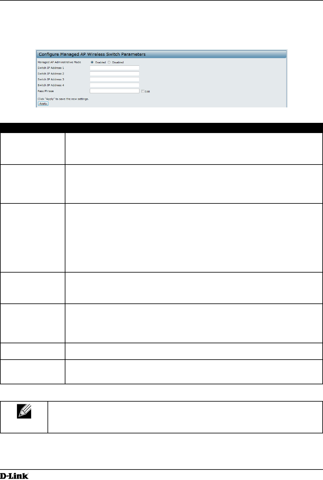
Figure 30 - Congure Managed AP Wireless Switch Parameters
Field Description
Managed AP
Administrative
Mode
Click Enabled to allow the AP and switch to discover each other. If the AP successfully
authenticates itself with a wireless switch, you will not be able to access the Administrator
UI.
Click Disabled to prevent the AP from contacting wireless switches.
Switch IP Address
(1-4)
Enter the IP address of up to four wireless switches that can manage the AP. You can
enter the IP address in dotted format or as an DNS name.
You can view a list of wireless switches on your network that were congured by using a
DHCP server.
The AP attempts to contact Switch IP Address 1 rst.
Base IP Port The starting IP port number used by the wireless feature (in a range of 10 consecutive port
numbers). Only the rst number in the range is congurable. The default value is 57775
(through 57784).
Note: When the wireless Base IP Port number is changed on the switch, the wireless
feature is automatically disabled and re-enabled. The new value is not sent as part of the
global switch conguration in the cluster conguration distribution command; every switch in
the cluster must be congured independently with the new Wireless IP port number.
Note: When the wireless Base IP Port number is changed from its default value on the
switch, it must also be changed on the Access Points.
Pass Phrase Select the Edit option and enter a passphrase to allow the AP to authenticate itself with the
wireless switch. The passphrase must be between 8 and 63 characters.
To remove the password, select Edit, delete the existing password, and then click Apply.
You must congure the same passphrase on the switch.
WDS Managed
Mode
Specify whether the AP will act as a Root AP or Satellite AP within the WDS group:
•) Root AP — Acts as a bridge or repeater on the wireless medium and communicates
with the switch via the wired link.
•) Satellite AP — Communicates with the switch via a WDS link to the Root AP. This
mode enables the Satellite AP to discover and establish WDS link with the Root AP.
WDS Managed
Ethernet Port
Specify whether the Ethernet port is to be enabled or disabled when the AP becomes part
of a WDS group.
WDS Group
Password
Password for WPA2 Personal authentication used to establish the WDS links. Only the
Satellite APs need this conguration. The Root APs get the password from the switch when
they become managed.
Table 33 - Managed Access Point
Note: After you congure the settings on the Managed Access Point page, you must click Apply
to apply the changes and to save the settings. Changing some settings might cause the AP to stop
and restart system processes. If this happens, wireless clients will temporarily lose connectivity.
We recommend that you change AP settings when WLAN trafc is low.
If the UAP successfully authenticates with a D-Link Unied Wireless Switch, you will loose access to the AP through
the Administrator UI.
Unied Access Point Administrator’s Guide
Unied Access Point Administrator’s Guide
Page 63
March 2012
Section 4 - Managing the Access Point
Conguring 802.1X Authentication
On networks that use IEEE 802.1X, port-based network access control, a supplicant (client) cannot gain access to
the network until the 802.1X authenticator grants access. If your network uses 802.1X, you must congure 802.1X
authentication information that the AP can supply to the authenticator.
To congure the UAP 802.1X supplicant user name and password by using the Web interface, click the
Authentication tab and congure the elds shown in the table below.
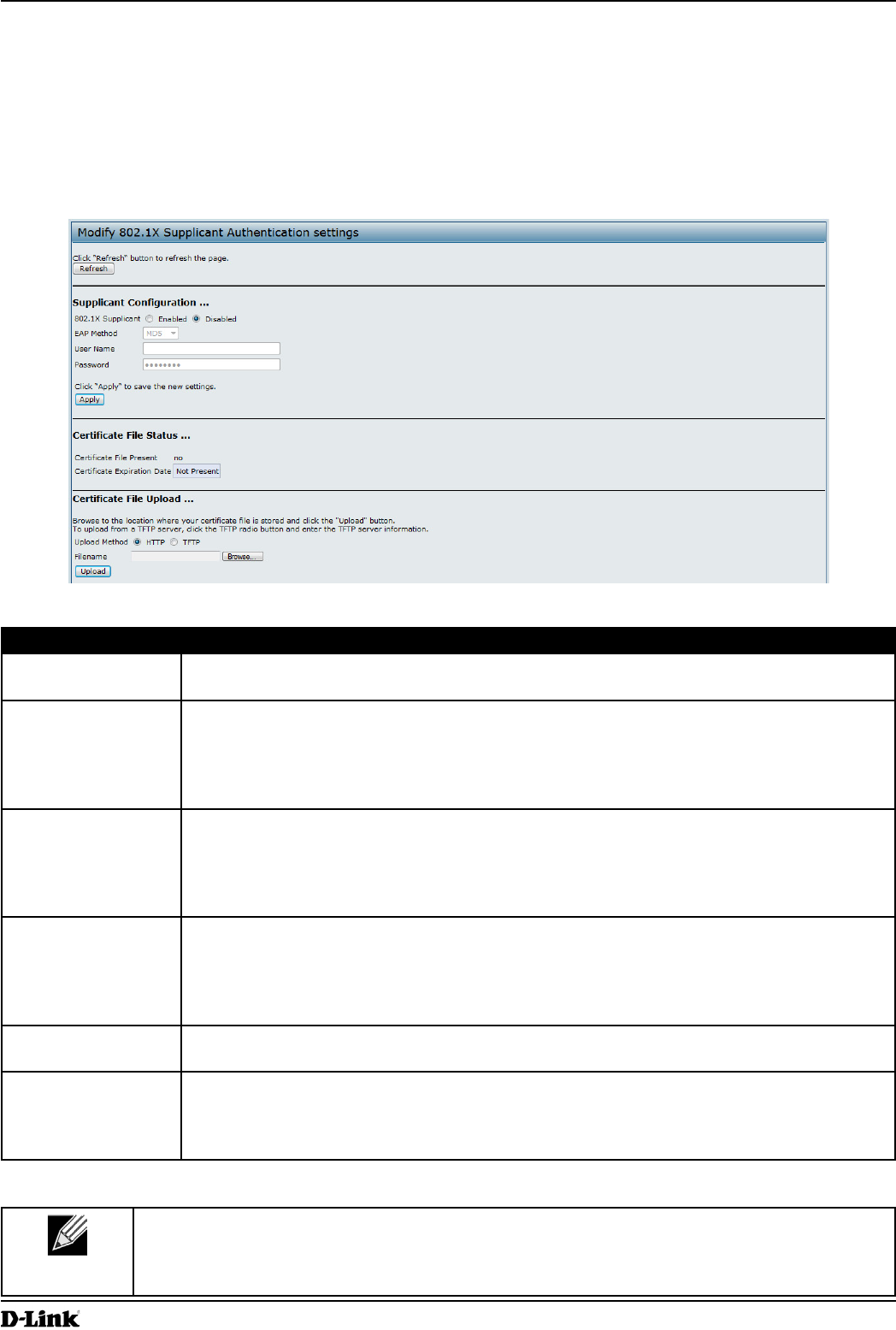
Figure 31 - Modify 802.1X Supplicant Authentication Settings
Field Description
802.1X Supplicant Click Enabled to enable the Administrative status of the 802.1X Supplicant.
Click Disabled to disable the Administrative status of the 802.1X Supplicant.
EAP Method Select one of the following EAP methods to use for communication between the AP and the
authenticator:
•) MD5
•) PEAP
•) TLS
Username Enter the user name for the AP to use when responding to requests from an 802.1X
authenticator.
The user name can be 1 to 64 characters in length. ASCII printable characters are allowed,
which includes upper and lower case alphabetic letters, the numeric digits, and special
symbols such as @ and #.
Password Enter the password for the AP to use when responding to requests from an 802.1X
authenticator.
The password can be 1 to 64 characters in length. ASCII printable characters are allowed,
which includes upper and lower case letters, numbers, and special symbols such as @ and
#.
Certicate File
Status
Indicates whether a certicate le is present and when that certicate expires.
Certicate File
Upload
Upload a certicate le to the AP by using HTTP or TFTP:
•) HTTP — Browse to the location where the certicate le is stored and click Upload.
•) TFTP — Specify the IP address of the TFTP server where the certicate le is located
and provide the le name, including the le path, then click Upload.
Table 34 - IEEE 802.1X Supplicant Authentication
Note: After you congure the settings on the Authentication page, you must click Apply to apply
the changes and to save the settings. Changing some settings might cause the AP to stop and
restart system processes. If this happens, wireless clients will temporarily lose connectivity. We
recommend that you change AP settings when WLAN trafc is low.
Unied Access Point Administrator’s Guide
Unied Access Point Administrator’s Guide
Page 64
March 2012
Section 4 - Managing the Access Point
Creating a Management Access Control List (ACL)
You can create an access control list (ACL) that lists up to ve IPv4 hosts and ve IPv6 hosts that are authorized to
access the AP management interface. If this feature is disabled, anyone can access the management interface from
any network client by supplying the correct AP username and password.
To create an access list, click the Management ACL tab.
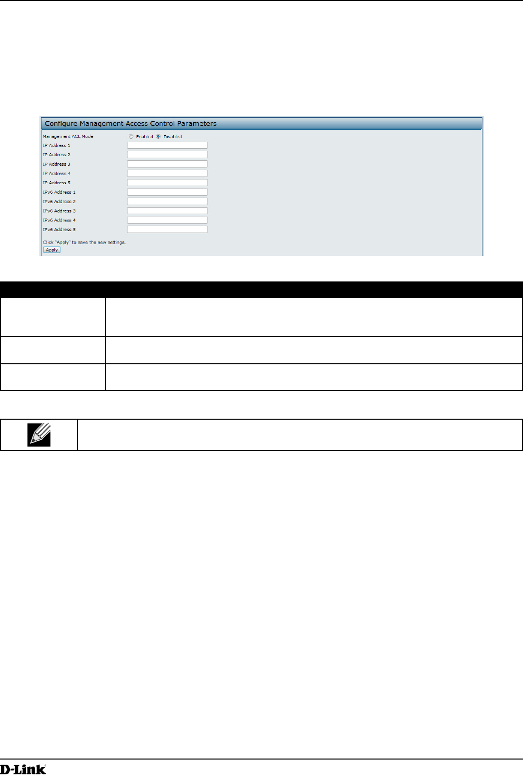
Figure 32 - Congure Management Access Control Parameters
Field Description
Management ACL
Mode
Enable or disable the management ACL feature. At least one IPv4 address should be
congured before enabling Management ACL Mode. If enabled, only the IP addresses you
specify will have Web, Telnet, SSH, and SNMP access to the management interface.
IP Address (1–5) Enter up to ve IPv4 addresses that are allowed management access to the AP. Use
dotted-decimal format (for example, 192.168.10.10).
IPv6 Address (1–5) Enter up to ve IPv6 addresses that are allowed management access to the AP. Use the
standard IPv6 address format (for example 2001:0db8:1234::abcd).
Table 35 - Management ACL
Note: After you congure the settings, click Apply to apply the changes and to save the settings.
Unied Access Point Administrator’s Guide
Unied Access Point Administrator’s Guide
Page 65
March 2012
Section 5 - Conguring Access Point Services
Section 5 - Conguring Access Point Services
This section describes how to congure services on the UAP and contains the following subsections:
•) “Web Server Settings” on page 65
•) “Conguring SNMP on the Access Point” on page 66
•) “Setting the SSH Status” on page 68
•) “Setting the Telnet Status” on page 69
•) “Conguring Quality of Service” on page 69
•) “Conguring Email Alert” on page 72
•) “Enabling the Time Settings (NTP)” on page 73
Web Server Settings
The AP can be managed through HTTP or secure HTTP (HTTPS) sessions. By default both HTTP and HTTPS access
are enabled. Either access type can be disabled separately.
To congure Web server settings, click Web Server tab.
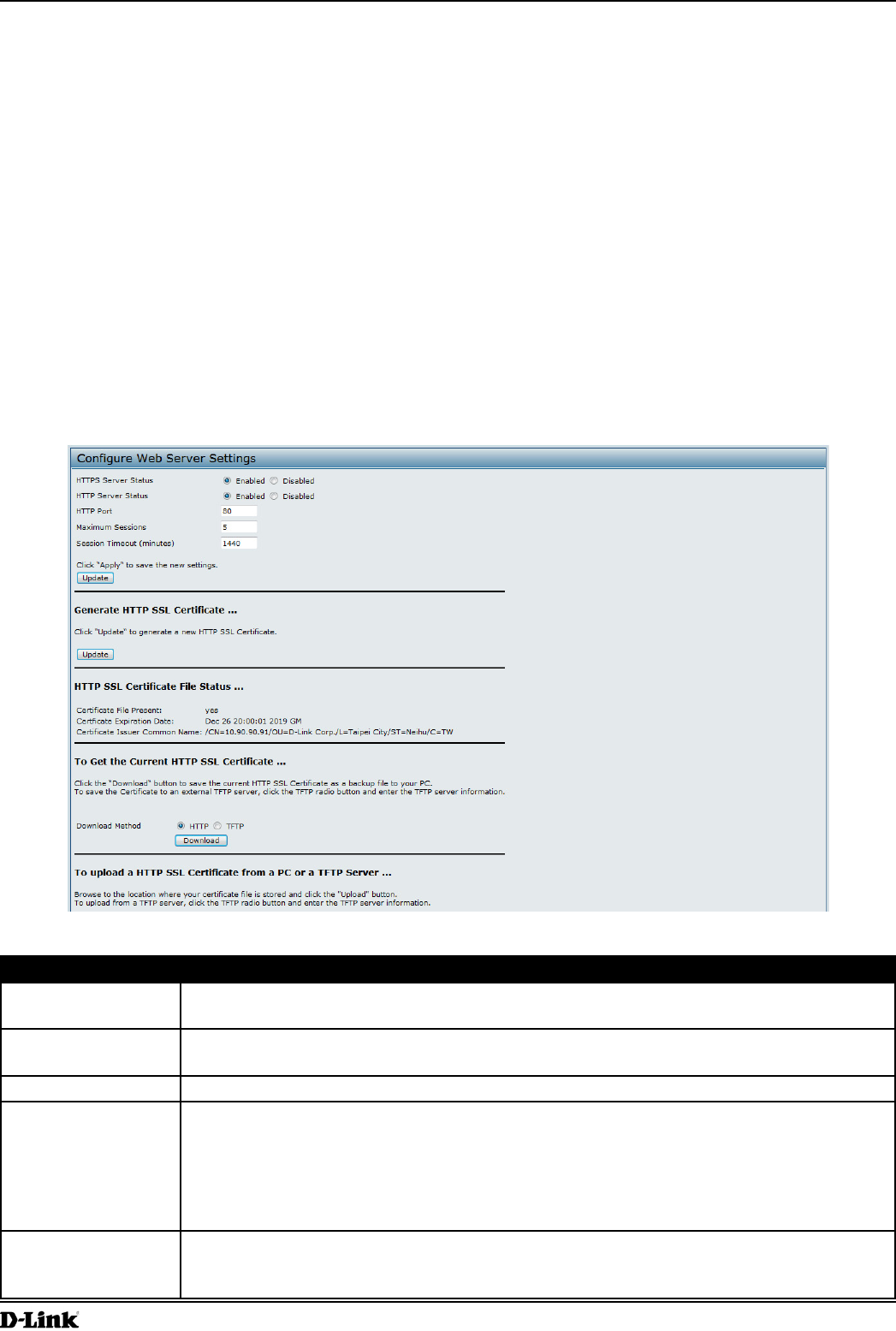
Figure 33 - Congure Web Server Settings
Field Description
HTTPS Server
Status
Enable or disable access through a Secure HTTP Server (HTTPS).
HTTP Server Status Enable or disable access through HTTP. This setting is independent of the HTTPS server
status setting.
HTTP Port Specify the port number for HTTP trafc (default is 80).
Maximum Sessions When a user logs on to the AP web interface, a session is created. This session is
maintained until the user logs off or the session inactivity timer expires.
Enter the number web sessions, including both HTTP and HTTPs, that can exist at the same
time. The range is 1–10 sessions. If the maximum number of sessions is reached, the next
user who attempts to log on to the AP web interface receives an error message about the
session limit.
Session Timeout Enter the maximum amount of time, in minutes, an inactive user remains logged on to the
AP web interface. When the congured timeout is reached, the user is automatically logged
off the AP. The range is 1–1440 minutes (1440 minutes = 1 day).
Unied Access Point Administrator’s Guide
Unied Access Point Administrator’s Guide
Page 66
March 2012
Section 5 - Conguring Access Point Services
Field Description
Generate HTTP SSL
Certicate
Select this option to generate a new SSL certicate for the secure Web server. This should
be done once the access point has an IP address to ensure that the common name for the
certicate matches the IP address of the UAP. Generating a new SSL certicate will restart
the secure Web server. The secure connection will not work until the new certicate is
accepted on the browser. Click the Update button to generate the new SSL certicate.
HTTP SSL
Certicate File
Status
Indicates whether a certicate le is present and species its expiration date and issuer
common name.
To Get the
Current HTTP SSL
Certicate
Save a copy of the current HTTP SSL certicate on a local system or TFTP server.
•) HTTP — Click Download and specify where to store the backup copy of the certicate
le.
•) TFTP — Provide a le name for the certicate le, including the le path, specify the
IP address of the TFTP server where the certicate le copy is to be stored, and then
click Download.
To upload a HTTP
SSL Certicate
from a PC or a TFTP
Server
Upload a certicate le to the AP by using HTTP or TFTP:
•) HTTP — Browse to the location where the certicate le is stored and click Upload.
•) TFTP — Specify the IP address of the TFTP server where the certicate le is located
and provide the le name, including the le path, then click Upload.
Table 36 - Web Server Settings
Note: Click Apply to apply the changes and to save the settings. If you disable the protocol you
are currently using to access the AP management interface, the current connection will end and
you will not be able to access the AP by using that protocol until it is enabled.
Conguring SNMP on the Access Point
Simple Network Management Protocol (SNMP) denes a standard for recording, storing, and sharing information
about network devices. SNMP facilitates network management, troubleshooting, and maintenance. The AP supports
SNMP versions 1, 2, and 3. Unless specically noted, all conguration parameters on this page apply to SNMPv1 and
SNMPv2c only.
Key components of any SNMP-managed network are managed devices, SNMP agents, and a management system.
The agents store data about their devices in Management Information Bases (MIBs) and return this data to the SNMP
manager when requested. Managed devices can be network nodes such as APs, routers, switches, bridges, hubs,
servers, or printers.
The UAP can function as an SNMP managed device for seamless integration into network management systems such
as HP OpenView.
From the SNMP page under the Services heading, you can start or stop control of SNMP agents, congure community
passwords, access MIBs, and congure SNMP Trap destinations.
From the pages under the SNMPv3 heading, you can manage SNMPv3 users and their security levels and dene
access control to the SNMP MIBs. For information about how to congure SNMPv3 views, groups, users, and targets,
see “Section 6 - Conguring SNMPv3” on page 75.
To congure SNMP, click the SNMP tab under the Services heading and update the elds described in the table
below.
Unied Access Point Administrator’s Guide
Unied Access Point Administrator’s Guide
Page 67
March 2012
Section 5 - Conguring Access Point Services
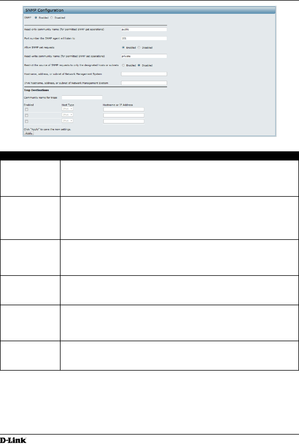
Figure 34 - SNMP Conguration
Field Description
SNMP Enabled/
Disabled
You can specify the SNMP administrative mode on your network. By default SNMP is
enabled. To enable SNMP, click Enabled. To disable SNMP, click Disabled. After changing
the mode, you must click Apply to save your conguration changes.
Note: If SNMP is disabled, all remaining elds on the SNMP page are disabled. This is a
global SNMP parameter which applies to SNMPv1, SNMPv2c, and SNMPv3.
Read-only
community name
(for permitted SNMP
get operations)
Enter a read-only community name. The valid range is 1-256 characters.
The community name, as dened in SNMPv2c, acts as a simple authentication mechanism
to restrict the machines on the network that can request data to the SNMP agent. The name
functions as a password, and the request is assumed to be authentic if the sender knows
the password.
The community name can be in any alphanumeric format.
Port number the
SNMP agent will
listen to
By default an SNMP agent only listens to requests from port 161. However, you can
congure this so the agent listens to requests on another port.
Enter the port number on which you want the SNMP agents to listen to requests. The valid
range is 1-65535.
Note: This is a global SNMP parameter that applies to SNMPv1, SNMPv2c, and SNMPv3.
Allow SNMP set
requests
You can choose whether or not to allow SNMP set requests on the AP. Enabling SNMP
set requests means that machines on the network can execute conguration changes via
the SNMP agent on the AP to the D-Link System MIB. To enable SNMP set requests, click
Enabled. To disable SNMP set requests, click Disabled.
Read-write
community name
(for permitted SNMP
set operations)
If you have enabled SNMP set requests you can set a read-write community name. The
valid range is 1-256 characters.
Setting a community name is similar to setting a password. Only requests from the
machines that identify themselves with this community name will be accepted.
The community name can be in any alphanumeric format.
Restrict the source
of SNMP requests to
only the designated
hosts or subnets
You can restrict the source of permitted SNMP requests.
To restrict the source of permitted SNMP requests, click Enabled.
To permit any source submitting an SNMP request, click Disabled.
Unied Access Point Administrator’s Guide
Unied Access Point Administrator’s Guide
Page 68
March 2012
Section 5 - Conguring Access Point Services
Field Description
Hostname,
address or subnet
of Network
Management
System
Specify the IPv4 DNS hostname or subnet of the machines that can execute get and set
requests to the managed devices. The valid range is 1-256 characters.
As with community names, this provides a level of security on SNMP settings. The SNMP
agent will only accept requests from the hostname or subnet specied here.
To specify a subnet, enter one or more subnetwork address ranges in the form address/
mask_length where address is an IP address and mask_length is the number of mask bits.
Both formats address/mask and address/mask_length are supported. Individual hosts
can be provided for this, i.e. IP Address or Hostname. For example, if you enter a range of
192.168.1.0/24 this species a subnetwork with address 192.168.1.0 and a subnet mask of
255.255.255.0.
The address range is used to specify the subnet of the designated NMS. Only machines
with IP addresses in this range are permitted to execute get and set requests on the
managed device. Given the example above, the machines with addresses from 192.168.1.1
through 192.168.1.254 can execute SNMP commands on the device. (The address
identied by sufx .0 in a subnetwork range is always reserved for the subnet address, and
the address identied by .255 in the range is always reserved for the broadcast address).
As another example, if you enter a range of 10.10.1.128/25 machines with IP addresses
from 10.10.1.129 through 10.10.1.254 can execute SNMP requests on managed devices. In
this example, 10.10.1.128 is the network address and 10.10.1.255 is the broadcast address.
126 addresses would be designated.
IPv6 Hostname
or IPv6 subnet
of Network
Management
System
Specify the IPv6 DNS hostname or subnet of the machines that can execute get and set
requests to the managed devices.
Community name
for traps
Enter the global community string associated with SNMP traps. The valid range is 1-256
characters.
Traps sent from the device will provide this string as a community name.
The community name can be in any alphanumeric format. Special characters are not
permitted.
Hostname or IP
address
Enter the DNS hostname of the computer to which you want to send SNMP traps. The valid
range is 1-256 characters.
An example of a DNS hostname is: snmptraps.foo.com. Since SNMP traps are sent
randomly from the SNMP agent, it makes sense to specify where exactly the traps should
be sent. You can add up to a maximum of three DNS hostnames. Ensure you select the
Enabled check box beside the appropriate hostname.
Table 37 - SNMP Settings
Note: After you congure the SNMP settings, you must click Apply to apply the changes and
to save the settings. Changing some settings might cause the AP to stop and restart system
processes. If this happens, wireless clients will temporarily lose connectivity. We recommend that
you change AP settings when WLAN trafc is low.
Setting the SSH Status
Secure Shell (SSH) is a program that provides access to the DWL-x600AP CLI from a remote host. SSH is more
secure than Telnet for remote access because it provides strong authentication and secure communications over
insecure channels. From the SSH page, you can enable or disable SSH access to the system.
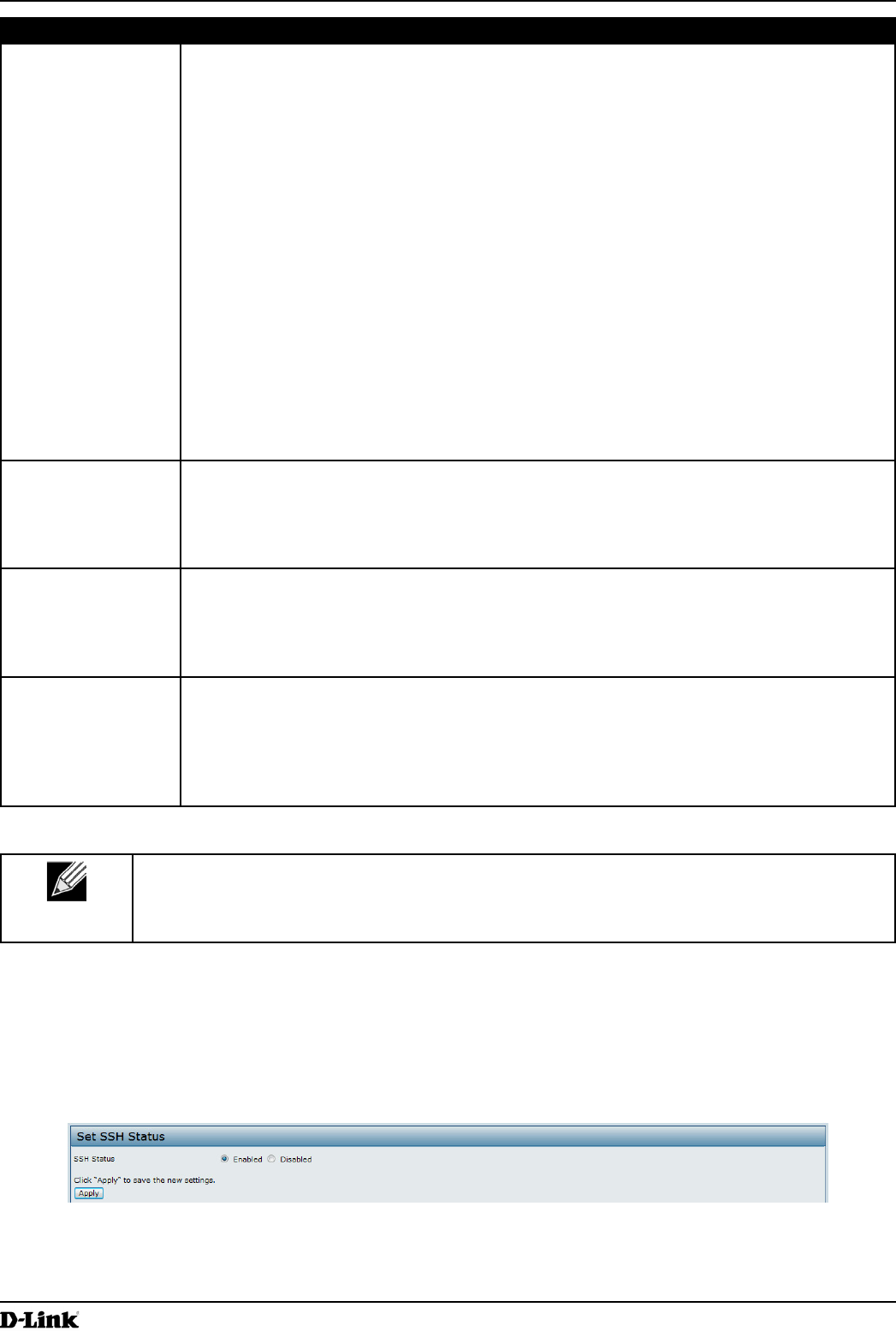
Figure 35 - Set SSH Status
Unied Access Point Administrator’s Guide
Unied Access Point Administrator’s Guide
Page 69
March 2012
Section 5 - Conguring Access Point Services
Field Description
SSH Status Choose to either enable or disable SSH access to the AP CLI:
•) To permit remote access to the AP by using SSH, click Enabled.
•) To prevent remote access to the AP by using SSH, click Disabled.
Table 38 - SSH Settings
Setting the Telnet Status
Telnet is a program that provides access to the DWL-x600AP CLI from a remote host. From the Telnet page, you can
enable or disable Telnet access to the system.
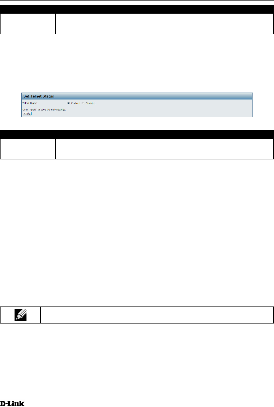
Figure 36 - Set Telnet Status
Field Description
Telnet Status Choose to either enable or disable Telnet access to the AP CLI:
•) To permit remote access to the AP by using Telnet, click Enabled.
•) To prevent remote access to the AP by using Telnet, click Disabled.
Table 39 - Telnet Settings
Conguring Quality of Service
Quality of Service (QoS) provides you with the ability to specify parameters on multiple queues for increased
throughput and better performance of differentiated wireless trafc like Voice-over-IP (VoIP), other types of audio,
video, and streaming media, as well as traditional IP data over the UAP.
Conguring QoS on the UAP consists of setting parameters on existing queues for different types of wireless trafc,
and effectively specifying minimum and maximum wait times (through Contention Windows) for transmission. The
settings described here apply to data transmission behavior on the AP only, not to that of the client stations.
AP Enhanced Distributed Channel Access (EDCA) Parameters affect trafc owing from the AP to the client station.
Station Enhanced Distributed Channel Access (EDCA) Parameters affect trafc owing from the client station to the
A P.
The default values for the AP and station EDCA parameters are those suggested by the Wi-Fi Alliance in the WMM
specication. In normal use these values should not need to be changed. Changing these values will affect the QoS
provided.
Note: On the DWL-6600AP and DWL-8600AP, the QoS settings apply to both radios, but the trafc
for each radio is queued independently.
To set up queues for QoS, click the QoS tab under the Services heading and congure settings as described in the
table below.
Unied Access Point Administrator’s Guide
Unied Access Point Administrator’s Guide
Page 70
March 2012
Section 5 - Conguring Access Point Services
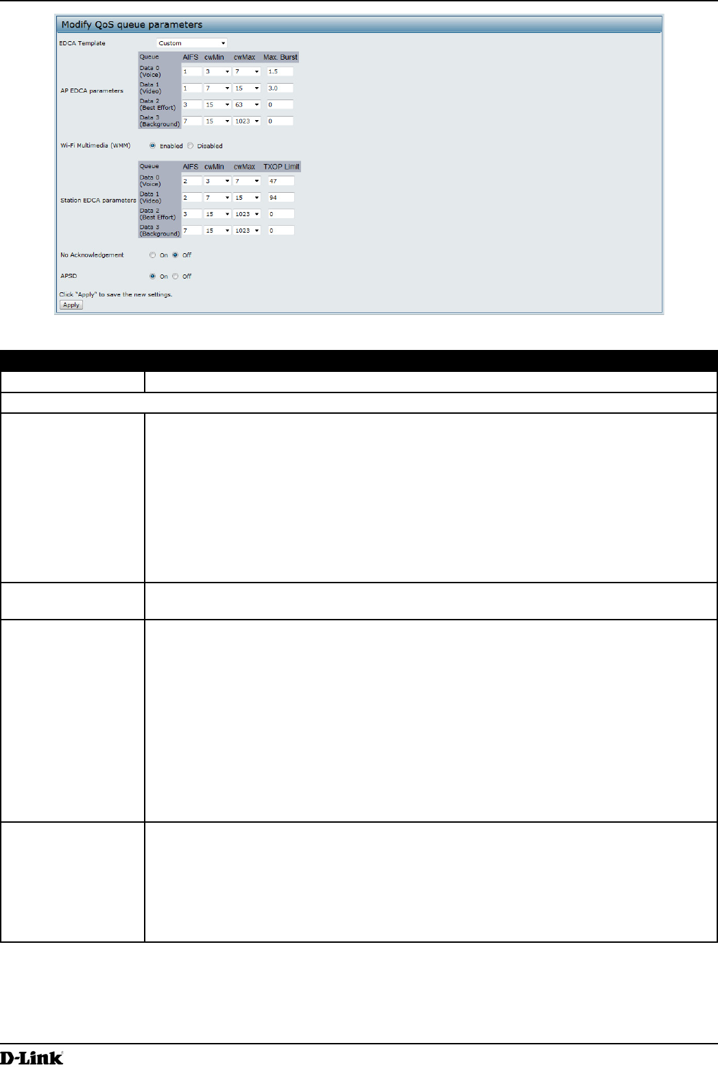
Figure 37 - Modify QoS Queue Parameters
Field Description
EDCA Template Possible options are: Default, Optimized for Voice, and Custom.
AP EDCA Parameters
Queue Queues are dened for different types of data transmitted from AP-to-station:
•) Data 0 (Voice) — High priority queue, minimum delay. Time-sensitive data such as
VoIP and streaming media are automatically sent to this queue.
•) Data 1(Video) — High priority queue, minimum delay. Time-sensitive video data is
automatically sent to this queue.
•) Data 2 (Best Effort) — Medium priority queue, medium throughput and delay. Most
traditional IP data is sent to this queue.
•) Data 3 (Background) — Lowest priority queue, high throughput. Bulk data that
requires maximum throughput and is not time-sensitive is sent to this queue (FTP
data, for example).
AIFS (Inter-Frame
Space)
The Arbitration Inter-Frame Spacing (AIFS) species a wait time for data frames. The wait
time is measured in slots. Valid values for AIFS are 1 through 255.
cwMin (Minimum
Contention Window)
This parameter is input to the algorithm that determines the initial random back off wait time
(window) for retry of a transmission.
The value specied for Minimum Contention Window is the upper limit (in milliseconds) of a
range from which the initial random back off wait time is determined.
The rst random number generated will be a number between 0 and the number specied
here.
If the rst random back off wait time expires before the data frame is sent, a retry counter
is incremented and the random back off value (window) is doubled. Doubling will continue
until the size of the random back off value reaches the number dened in the Maximum
Contention Window.
Valid values for cwMin are 1, 3, 7, 15, 31, 63, 127, 255, 511, or 1024. The value for cwMin
must be lower than the value for cwMax.
cwMax (Maximum
Contention Window)
The value specied for the Maximum Contention Window is the upper limit (in milliseconds)
for the doubling of the random back off value. This doubling continues until either the data
frame is sent or the Maximum Contention Window size is reached.
Once the Maximum Contention Window size is reached, retries will continue until a
maximum number of retries allowed is reached.
Valid values for cwMax are 1, 3, 7, 15, 31, 63, 127, 255, 511, or 1024. The value for cwMax
must be higher than the value for cwMin.

Unied Access Point Administrator’s Guide
Unied Access Point Administrator’s Guide
Page 71
March 2012
Section 5 - Conguring Access Point Services
Field Description
Max. Burst Length The Max. Burst Length is an AP EDCA parameter and only applies to trafc owing from
the AP to the client station.
This value species (in milliseconds) the maximum burst length allowed for packet bursts
on the wireless network. A packet burst is a collection of multiple frames transmitted without
header information. The decreased overhead results in higher throughput and better
performance.
Valid values for maximum burst length are 0.0 through 999.
Wi-Fi Multimedia (WMM) Settings
Wi-Fi MultiMedia
(WMM)
Wi-Fi MultiMedia (WMM) is enabled by default. With WMM enabled, QoS prioritization and
coordination of wireless medium access is on. With WMM enabled, QoS settings on the
UAP control downstream trafc owing from the AP to client station (AP EDCA parameters)
and the upstream trafc owing from the station to the AP (station EDCA parameters).
Disabling WMM deactivates QoS control of station EDCA parameters on upstream trafc
owing from the station to the AP.
With WMM disabled, you can still set some parameters on the downstream trafc owing
from the AP to the client station (AP EDCA parameters).
To disable WMM extensions, click Disabled.
To enable WMM extensions, click Enabled.
Station EDCA Parameters
Queue Queues are dened for different types of data transmitted from station-to-AP:
•) Data 0 (Voice) — Highest priority queue, minimum delay. Time-sensitive data such as
VoIP and streaming media are automatically sent to this queue.
•) Data 1(Video) — Highest priority queue, minimum delay. Time-sensitive video data is
automatically sent to this queue.
•) Data 2 (Best Effort) — Medium priority queue, medium throughput and delay. Most
traditional IP data is sent to this queue.
•) Data 3 (Background) — Lowest priority queue, high throughput. Bulk data that
requires maximum throughput and is not time-sensitive is sent to this queue (FTP
data, for example).
AIFS (Inter-Frame
Space)
The Arbitration Inter-Frame Spacing (AIFS) species a wait time for data frames. The wait
time is measured in slots. Valid values for AIFS are 1 through 255.
cwMin (Minimum
Contention Window)
This parameter is used by the algorithm that determines the initial random back off wait
time (window) for retry of a data transmission during a period of contention for Unied
Access Point resources. The value specied here in the Minimum Contention Window is
the upper limit (in milliseconds) of a range from which the initial random back off wait time
will be determined. The rst random number generated will be a number between 0 and the
number specied here. If the rst random back off wait time expires before the data frame
is sent, a retry counter is incremented and the random back off value (window) is doubled.
Doubling will continue until the size of the random back off value reaches the number
dened in the Maximum Contention Window.
cwMax (Maximum
Contention Window)
The value specied here in the Maximum Contention Window is the upper limit (in
milliseconds) for the doubling of the random back off value. This doubling continues until
either the data frame is sent or the Maximum Contention Window size is reached.
Once the Maximum Contention Window size is reached, retries will continue until a
maximum number of retries allowed is reached.
TXOP Limit The TXOP Limit is a station EDCA parameter and only applies to trafc owing from the
client station to the AP. The Transmission Opportunity (TXOP) is an interval of time, in
milliseconds, when a WME client station has the right to initiate transmissions onto the
wireless medium (WM) towards the Unied Access Point. The TXOP Limit maximum value is
65535.
Other QoS Settings
No
Acknowledgement
Select On to specify that the AP should not acknowledge frames with QosNoAck as the
service class value.
APSD Select On to enable Automatic Power Save Delivery (APSD), which is a power management
method. APSD is recommended if VoIP phones access the network through the AP.
Unied Access Point Administrator’s Guide
Unied Access Point Administrator’s Guide
Page 72
March 2012
Section 5 - Conguring Access Point Services
Note: After you congure the QoS settings, you must click Apply to apply the changes and to save
the settings. Changing some settings might cause the AP to stop and restart system processes. If
this happens, wireless clients will temporarily lose connectivity. We recommend that you change
AP settings when WLAN trafc is low.
Table 40 - QoS Settings
Conguring Email Alert
The Email Alert feature allows the AP to automatically send email messages when an event at or above the congured
severity level occurs. Use the Email Alert Conguration page to congure mail server settings, to set the severity level
that triggers alerts, and to add up to three email addresses where urgent and non-urgent email alerts are sent.
Note: Email alert is operationally disabled when the AP transitions to managed mode.
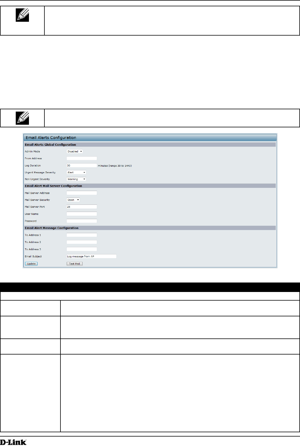
Figure 38 - Email Alerts Conguration
Field Description
Email Alert Global Conguration
Admin Mode Globally enable or disable the Email Alert feature on the AP. By default, email alerts are
disabled.
From Address Specify the email address that appears in the From eld of alert messages sent from the AP,
for example dlinkAP23@foo.com. The address can be a maximum of 255 characters and
can contain only printable characters. By default, no address is congured.
Log Duration This duration, in minutes, determines how frequently the non-critical messages are sent to
the SMTP Server. The range is 30-1440 minutes. The default is 30 minutes.
Urgent Message
Severity
Congures the severity level for log messages that are considered to be urgent. Messages
in this category are sent immediately. The security level you select and all higher levels are
urgent:
•) Emergency indicates system is unusable. It is the highest level of severity.
•) Alert indicates action must be taken immediately.
•) Critical indicates critical conditions.
•) Error indicates error conditions.
•) Warning indicates warning conditions.
•) Notice indicates normal but signicant conditions.
•) Info indicates informational messages.
•) Debug indicates debug-level messages.
Unied Access Point Administrator’s Guide
Unied Access Point Administrator’s Guide
Page 73
March 2012
Section 5 - Conguring Access Point Services
Field Description
Non Urgent Severity Congures the severity level for log messages that are considered to be non-urgent.
Messages in this category are collected and sent in a digest form at the time interval
specied by the Log Duration eld. The security level you select and all levels up to, but not
including the lowest Urgent level are considered non-urgent. Messages below the security
level you specify are not sent via email.
See the Urgent Message eld description for information about the security levels.
Email Alert Mail Server Conguration
Mail Server Address Specify the IP address or hostname of the SMTP server on the network.
Mail Server Security Specify whether to use SMTP over SSL (TLSv1) or no security (Open) for authentication
with the mail server. The default is Open.
Mail Server Port Congures the TCP port number for SMTP. The range is a valid port number from 0 to
65535. The default is 25, which is the standard port for SMTP.
Username Specify the username to use when authentication with the mail server is required. The
username is a 64-byte character string with all printable characters. The default is admin.
Password Specify the password associated with the username congured in the previous eld.
Email Alert Message Conguration
To Address 1 Congure the rst email address to which alert messages are sent. The address must be a
valid email address. By default, no address is congured.
To Address 2 Optionally, congure the second email address to which alert messages are sent. The
address must be a valid email address. By default, no address is congured.
To Address 3 Optionally, congure the third email address to which alert messages are sent. The address
must be a valid email address. By default, no address is congured.
Email Subject Specify the text to be displayed in the subject of the email alert message. The subject can
contain up to 255 alphanumeric characters. The default is Log message from AP.
Table 41 - Email Alert Conguration
Note: After you congure the Email Alert settings, click Apply to apply the changes and to save
the settings.
To validate the congured email server credentials, click Test Mail. You can send a test email once the email server
details are congured.
The following text shows an example of an email alert sent from the AP to the network administrator:
From: AP-192.168.2.10@mailserver.com
Sent: Wednesday, July 08, 2011 11:16 AM
To: administrator@mailserver.com
Subject: log message from AP
TIME Priority Process Id Message
Jul 8 03:48:25 info login[1457] root login on ‘ttyp0’
Jul 8 03:48:26 info mini_http-ssl[1175] Max concurrent connections of 20 reached
Enabling the Time Settings (NTP)
Use the Time Settings page to specify the Network Time Protocol (NTP) server to use to provide time and date
information to the AP or to congure the time and date information manually.
NTP is an Internet standard protocol that synchronizes computer clock times on your network. NTP servers transmit
Coordinated Universal Time (UTC, also known as Greenwich Mean Time) to their client systems. NTP sends periodic
time requests to servers, using the returned time stamp to adjust its clock. The timestamp is used to indicate the date
and time of each event in log messages.
See http://www.ntp.org for more information about NTP.
Unied Access Point Administrator’s Guide
Unied Access Point Administrator’s Guide
Page 74
March 2012
Section 5 - Conguring Access Point Services
To set the system time either manually or by specifying the address of the NTP server for the AP to use, click the
Services > Time Settings (NTP) tab and update the elds as described in the table below.
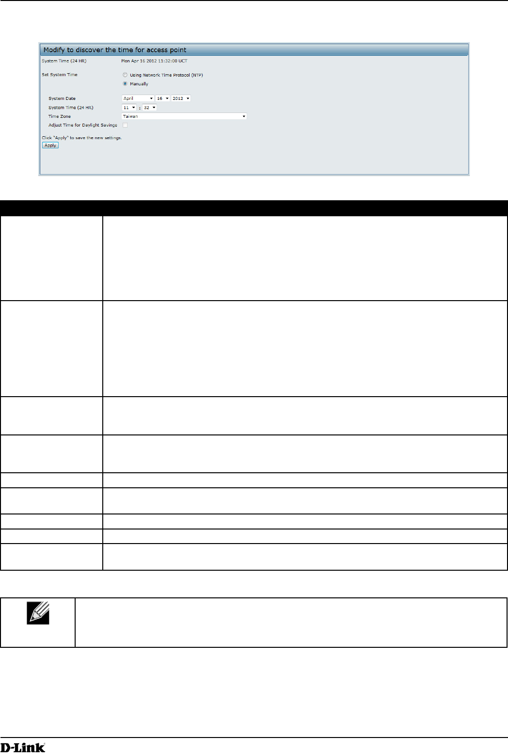
Figure 39 - Time Settings (NTP)
Field Description
Set System Time NTP provides a way for the AP to obtain and maintain its time from a server on the network.
Using an NTP server gives your AP the ability to provide the correct time of day in log
messages and session information.
Choose to use a network time protocol (NTP) server to determine the system time, or set the
system time manually:
•) To permit the AP to poll an NTP server, click Using Network Time Protocol (NTP).
•) To prevent the AP from polling an NTP server, click Manually.
NTP Server (Use
NTP)
If NTP is enabled, specify the NTP server to use.
You can specify the NTP server by hostname or IP address, although using the IP address
is not recommended as these can change more readily.
If you specify a hostname, note the following requirements:
•) The length must be between 1 – 63 characters.
•) Upper and lower case characters, numbers, and hyphens are accepted.
•) The rst character must be a letter (a–z or A–Z), and the last character cannot be a
hyphen.
System Date
(Manual
conguration)
Specify the current month, day, and year.
System Time
(Manual
conguration)
Specify the current time in hours and minutes. The system uses a 24-hour clock, so 6:00 PM
is congured as 18:00.
Time Zone Select your local time zone from the menu. The default is USA (Pacic).
Adjust Time for
Daylight Savings
Select to have the system adjust the reported time for Daylight Savings Time (DST). When
this eld is selected, elds to congure Daylight Savings Time settings appear.
DST Start (24 HR) Congure the date and time to begin Daylight Savings Time for the System Time.
DST End (24 HR) Congure the date and time to end Daylight Savings Time for the System Time.
DST Offset
(minutes)
Select the number of minutes to offset DST. The default is 60 minutes.
Table 42 - NTP Settings
Note: After you congure the Time settings, you must click Apply to apply the changes and
to save the settings. Changing some settings might cause the AP to stop and restart system
processes. If this happens, wireless clients will temporarily lose connectivity. We recommend that
you change AP settings when WLAN trafc is low.
Unied Access Point Administrator’s Guide
Unied Access Point Administrator’s Guide
Page 75
March 2012
Section 6 - Conguring SNMPv3
Section 6 - Conguring SNMPv3
This section describes how to congure the SNMPv3 settings on the UAP and contains the following subsections:
•) “Conguring SNMPv3 Views” on page 75
•) “Conguring SNMPv3 Groups” on page 76
•) “Conguring SNMPv3 Users” on page 77
•) “Conguring SNMPv3 Targets” on page 78
Conguring SNMPv3 Views
A MIB view is a combination of a set of view subtrees or a family of view subtrees where each view subtree is a
subtree within the managed object naming tree. You can create MIB views to control the OID range that SNMPv3
users can access.
A MIB view called “all” is created by default in the system. This view contains all management objects supported by
the system.
Note: If you create an excluded view subtree, create a corresponding included entry with the
same view name to allow subtrees outside of the excluded subtree to be included. For example, to
create a view that excludes the subtree 1.3.6.1.4, create an excluded entry with the OID 1.3.6.1.4.
Then, create an included entry with OID .1 with the same view name.
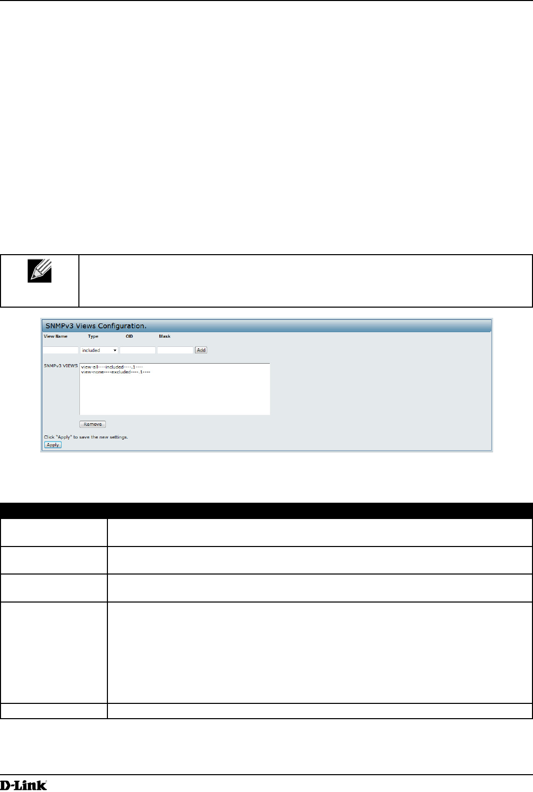
Figure 40 - SNMPv3 Views Conguration
The following table describes the elds you can congure on the SNMPv3 Views page.
Field Description
View Name Enter a name to identify the MIB view.
View names can contain up to 32 alphanumeric characters.
Type Species whether to include or exclude the view subtree or family of subtrees from the MIB
view.
OID Enter an OID string for the subtree to include or exclude from the view.
For example, the system subtree is specied by the OID string .1.3.6.1.2.1.1.
Mask The OID mask is 47 characters in length. The format of the OID mask is xx.xx.xx (.)... or
xx:xx:xx.... (:) and is 16 octets in length. Each octet is 2 hexadecimal characters separated
by either . (period) or : (colon). Only hex characters are accepted in this eld. For example,
OID mask FA.80 is 11111010.10000000.
A family mask is used to dene a family of view subtrees. The family mask indicates which
sub-identiers of the associated family OID string are signicant to the family’s denition.
A family of view subtrees allows control access to one row in a table, in a more efcient
manner.
SNMPv3 Views This eld shows the MIB views on the UAP. To remove a view, select it and click Remove.
Table 43 - SNMPv3 Views
Unied Access Point Administrator’s Guide
Unied Access Point Administrator’s Guide
Page 76
March 2012
Section 6 - Conguring SNMPv3
Note: After you congure the SNMPv3 Views settings, you must click Apply to apply the changes
and to save the settings.
Conguring SNMPv3 Groups
SNMPv3 groups allow you to combine users into groups of different authorization and access privileges.
By default, the UAP has two groups:
•) RO — A read-only group using authentication and data encryption. Users in this group use an MD5 key/
password for authentication and a DES key/password for encryption. Both the MD5 and DES key/passwords
must be dened. By default, users of this group will have read only access to the default all MIB view, which can
be modied by the user.
•) RW — A read/write group using authentication and data encryption. Users in this group use an MD5 key/
password for authentication and a DES key/password for encryption. Both the MD5 and DES key/passwords
must be dened. By default, users of this group will have read and write access to the default all MIB view,
which can be modied by the user.
RW and RO groups are dened by default.
Note: The UAP supports maximum of eight groups.
To dene additional groups, navigate to the SNMPv3 Groups page and congure the settings that the table below
describes.
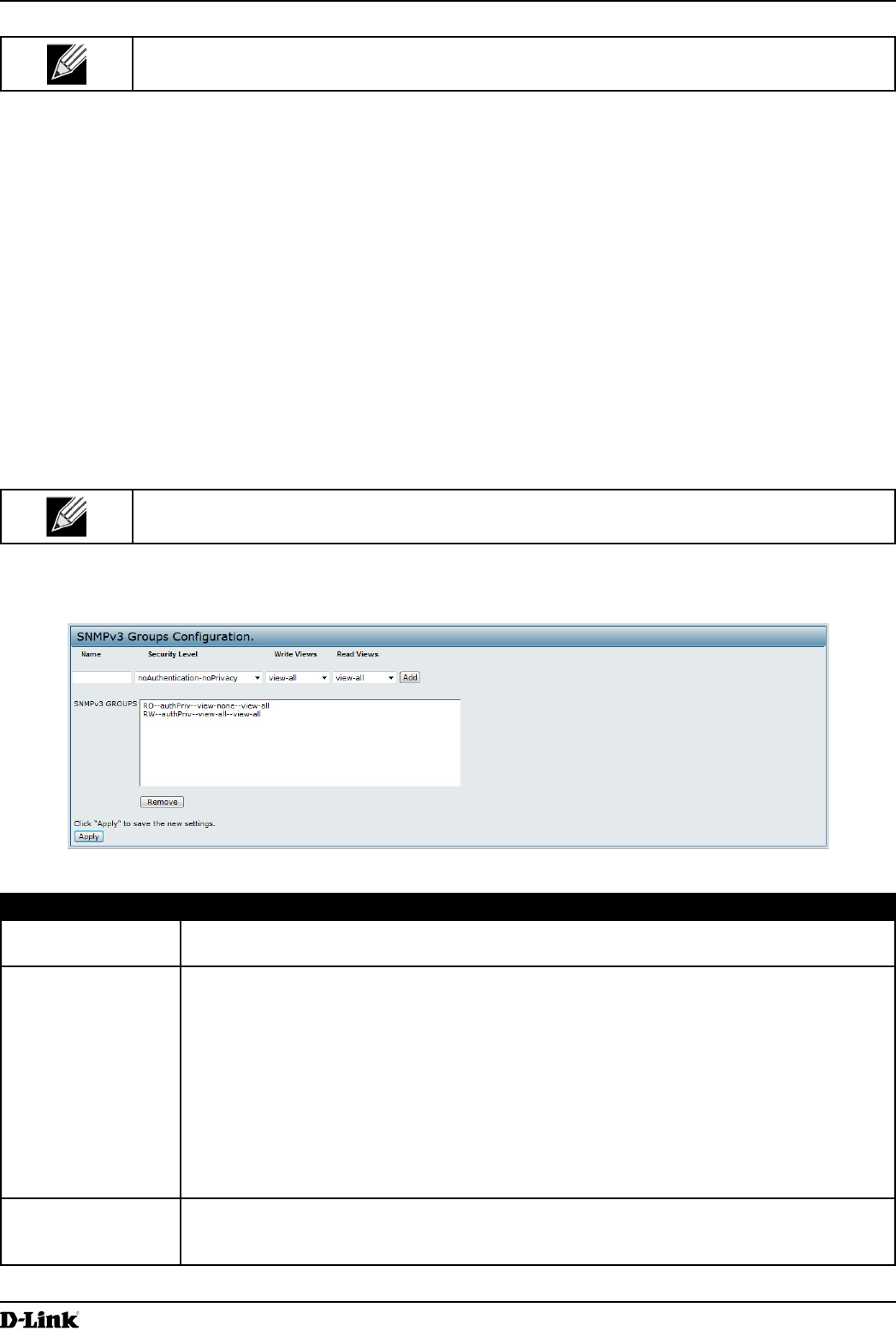
Figure 41 - SNMPv3 Groups Conguration
Field Description
Name Specify a name to use to identify the group. The default group names are RW and RO.
Group names can contain up to 32 alphanumeric characters.
Security Level Select one of the following security levels for the group:
•) noAuthentication-noPrivacy — No authentication and no data encryption (no
security).
•) Authentication-noPrivacy — Authentication, but no data encryption. With this security
level, users send SNMP messages that use an MD5 key/password for authentication,
but not a DES key/password for encryption.
•) Authentication-Privacy — Authentication and data encryption. With this security level,
users send an MD5 key/password for authentication and a DES key/password for
encryption.
For groups that require authentication, encryption, or both, you must dene the MD5 and
DES key/passwords on the SNMPv3 Users page.
Write Views Select the write access to management objects (MIBs) for the group:
•) write-all — The group can create, alter, and delete MIBs.
•) write-none — The group is not allowed to create, alter, or delete MIBS.
Unied Access Point Administrator’s Guide
Unied Access Point Administrator’s Guide
Page 77
March 2012
Section 6 - Conguring SNMPv3
Field Description
Read Views Select the read access to management objects (MIBs) for the group:
•) view-all — The group is allowed to view and read all MIBs.
•) view-none — The group cannot view or read MIBs.
SNMPv3 Groups This eld shows the default groups and the groups that you have dened on the AP. To
remove a group, select the group and click Remove.
Table 44 - SNMPv3 Groups
Note: After you congure the SNMPv3 Groups settings, you must click Apply to apply the changes
and to save the settings.
Conguring SNMPv3 Users
From the SNMPv3 Users page, you can dene multiple users, associate the desired security level to each user, and
congure security keys.
For authentication, only MD5 type is supported, and for encryption only DES type is supported. There are no default
SNMPv3 users on the UAP.
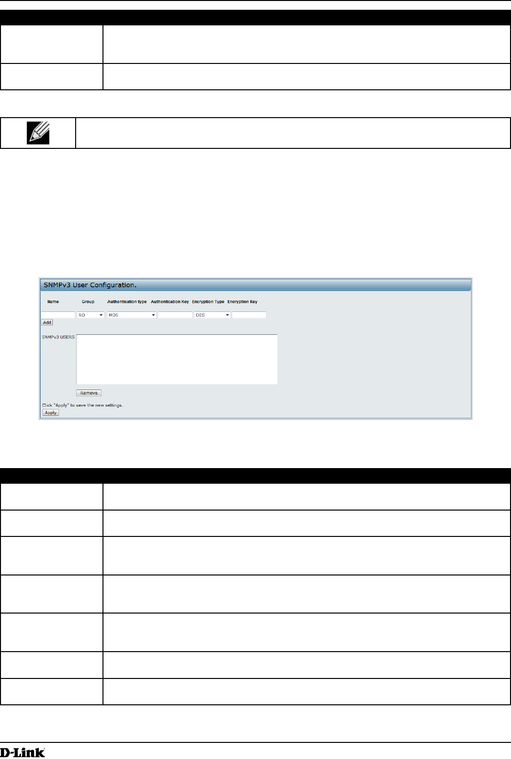
Figure 42 - SNMPv3 User Conguration
The following table describes the elds to congure SNMPv3 users.
Field Description
Name Enter the user name to identify the SNMPv3 user.
User names can contain up to 32 alphanumeric characters.
Group Map the user to a group. The default groups are RWAuth, RWPriv, and RO. You can dene
additional groups on the SNMPv3 Groups page.
Authentication Type Select the type of authentication to use on SNMP requests from the user:
•) MD5 — Require MD5 authentication on SNMPv3 requests from the user.
•) None — SNMPv3 requests from this user require no authentication.
Authentication Key If you specify MD5 as the authentication type, enter a password to enable the SNMP agent
to authenticate requests sent by the user.
The passphrase must be between 8 and 32 characters in length.
Encryption Type Select the type of privacy to use on SNMP requests from the user:
•) DES — Use DES encryption on SNMPv3 requests from the user.
•) None — SNMPv3 requests from this user require no privacy.
Encryption Key If you specify DES as the privacy type, enter a key to use to encrypt the SNMP requests.
The passphrase must be between 8 and 32 characters in length.
SNMPv3 Users This eld shows the users that you have dened on the AP. To remove a user, select the
user and click Remove.
Table 45 - SNMPv3 Users
Unied Access Point Administrator’s Guide
Unied Access Point Administrator’s Guide
Page 78
March 2012
Section 6 - Conguring SNMPv3
Note: After you congure the SNMPv3 Users settings, you must click Apply to apply the changes
and to save the settings.
Conguring SNMPv3 Targets
SNMPv3 Targets send “inform” messages to the SNMP manager. Each target is identied by a target name and
associated with target IP address, UDP port, and SNMP user name.
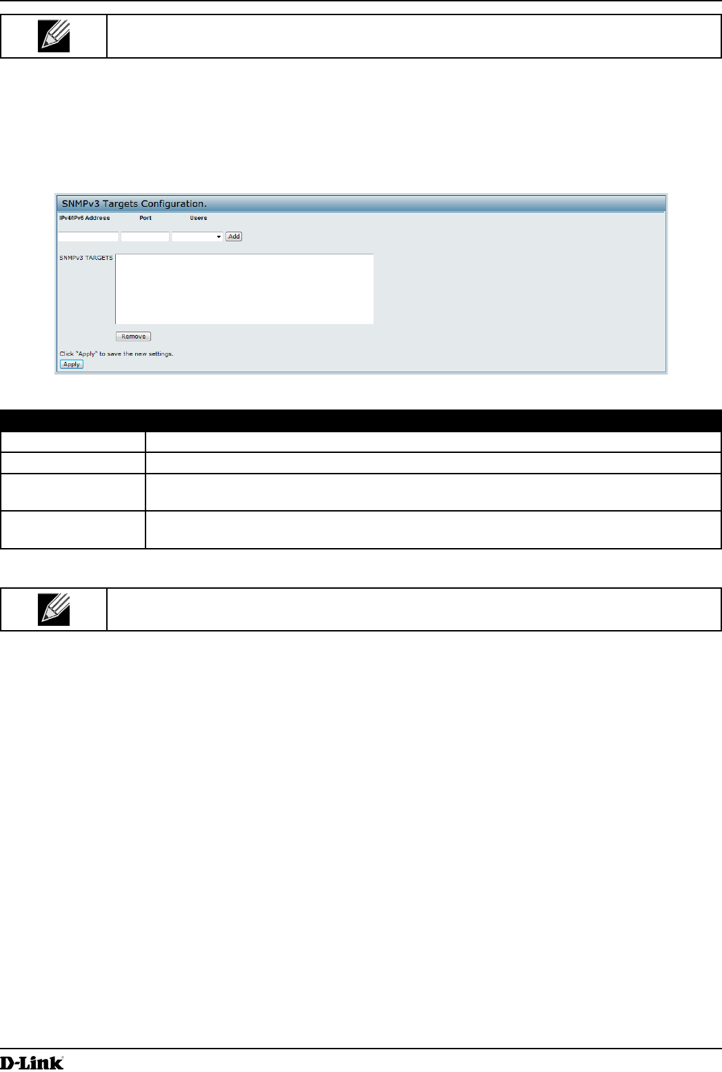
Figure 43 - SNMPv3 Targets Conguration
Field Description
IPv4/IPv6 Address Enter the IP address of the remote SNMP manager to receive the target.
Port Enter the UDP port to use for sending SNMP targets.
Users Select the name of the SNMP user to associate with the target. To congure SNMP users,
see “Conguring SNMPv3 Users” on page 77.
SNMPv3 Targets This eld shows the SNMPv3 Targets on the UAP. To remove a target, select it and click
Remove.
Table 46 - SNMPv3 Targets
Note: After you congure the SNMPv3 Target settings, you must click Apply to apply the changes
and to save the settings.
Unied Access Point Administrator’s Guide
Unied Access Point Administrator’s Guide
Page 79
March 2012
Section 7 - Maintaining the Access Point
Section 7 - Maintaining the Access Point
This section describes how to maintain the UAP.
From the UAP Administrator UI, you can perform the following maintenance tasks:
•) “Saving the Current Conguration to a Backup File” on page 79
•) “Restoring the Conguration from a Previously Saved File” on page 80
•) “Rebooting the Access Point” on page 81
•) “Performing AP Maintenance” on page 81
•) “Resetting the Factory Default Conguration” on page 81
•) “Upgrading the Firmware” on page 81
•) “Packet Capture Conguration and Settings” on page 83
Saving the Current Conguration to a Backup File
The AP conguration le is in XML format and contains all of the information about the AP settings. You can download
the conguration le to a management station to manually edit the content or to save as a back-up copy.
You can use HTTP or TFTP to transfer les to and from the UAP. After you download a conguration le to the
management station, you can manually edit the le, which is in XML format. Then, you can upload the edited
conguration le to apply those conguration settings to the AP.
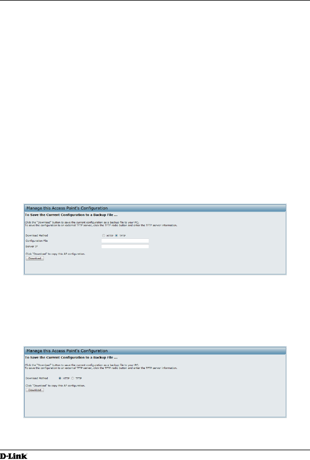
Use the following steps to save a copy of the current settings on an AP to a backup conguration le by using TFTP:
1.) Select TFTP for Download Method.
Figure 44 - Manage this Access Point’s Conguration - Save (TFTP)
2.) Enter a name (1 to 63 characters) for the backup le in the Conguration File eld, including the .xml le name
extension and the path to the directory where you want to save the le.
3.) Enter the Server IP address of the TFTP server.
4.) Click Download to save a copy of the le to the TFTP server.
Use the following steps to save a copy of the current settings on an AP to a backup conguration le by using HTTP:
1.) Select HTTP for Download Method.
Figure 45 - Manage this Access Point’s Conguration - Save (HTTP)
2.) Click the Download button.
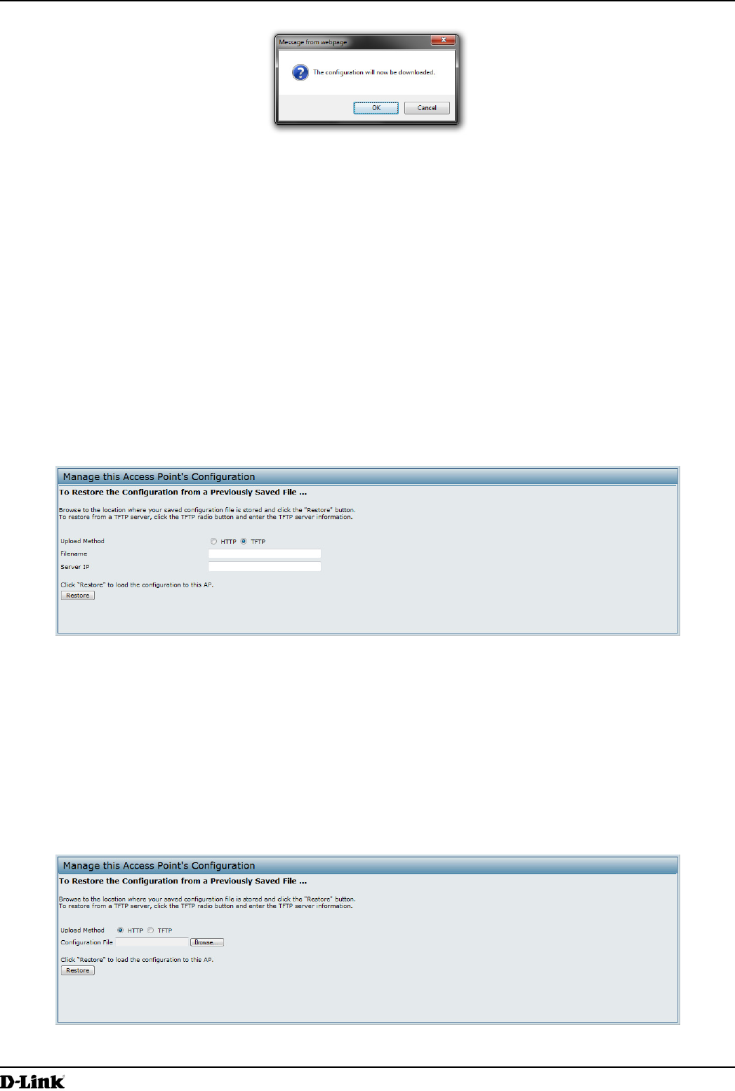
A dialog box displays verifying the download.
Unied Access Point Administrator’s Guide
Unied Access Point Administrator’s Guide
Page 80
March 2012
Section 7 - Maintaining the Access Point
Figure 46 - Conrmation Prompt
3.) To proceed with the download, select OK.
A dialog box opens allowing you to view or save the le.
4.) Select the Save File option and select OK.
5.) Use the le browser to navigate to the directory where you want to save the le, and click OK to save the le.
You can keep the default le name (cong.xml) or rename the backup le, but be sure to save the le with an
.xml extension.
Restoring the Conguration from a Previously Saved File
You can use HTTP or TFTP to transfer les to and from the UAP. After you download a conguration le to the
management station, you can manually edit the le, which is in XML format. Then, you can upload the edited
conguration le to apply those conguration settings to the AP.
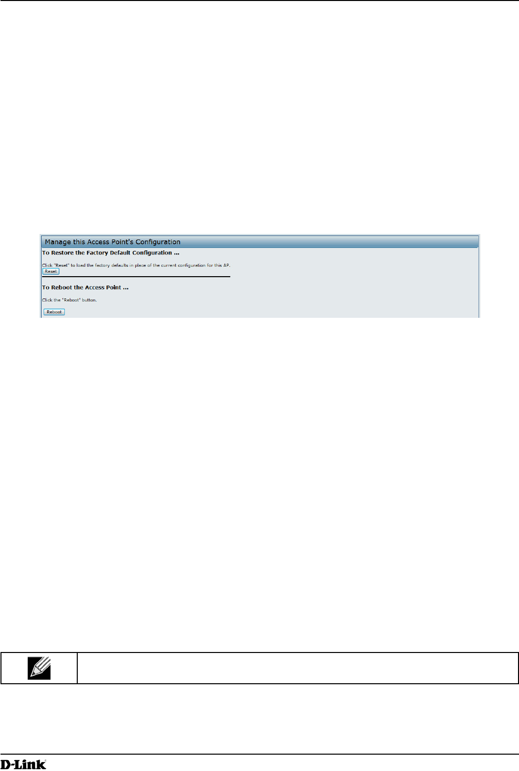
Use the following procedures to restore the conguration on an AP to previously saved settings by using TFTP:
1.) Select TFTP for Upload Method.
Figure 47 - Manage this Access Point’s Conguration - Restore (TFTP)
2.) Enter a name (1 to 63 characters) for the backup le in the Filename eld, including the .xml le name extension
and the path to the directory that contains the conguration le to upload.
3.) Enter the IP address of the TFTP server in the Server IP eld.
4.) Click the Restore button.
The AP reboots. A reboot conrmation dialog and follow-on rebooting status message displays. Please wait for
the reboot process to complete, which might take several minutes.
The Administration Web UI is not accessible until the AP has rebooted.
Use the following steps to save a copy of the current settings on an AP to a backup conguration le by using HTTP:
1.) Select HTTP for Upload Method.
Figure 48 - Manage this Access Point’s Conguration - Restore (HTTP)
Unied Access Point Administrator’s Guide
Unied Access Point Administrator’s Guide
Page 81
March 2012
Section 7 - Maintaining the Access Point
2.) Use the Browse button to select the le to restore.
3.) Click the Restore button.
A File Upload or Choose File dialog box displays.
4.) Navigate to the directory that contains the le, then select the le to upload and click Open.
(Only those les created with the Backup function and saved as .xml backup conguration les are valid to use
with Restore; for example, ap_cong.xml.)
5.) Click the Restore button.
A dialog box opens verifying the restore.
6.) Click OK to proceed.
The AP reboots. A reboot conrmation dialog and follow-on rebooting status message displays. Please wait for
the reboot process to complete, which might take several minutes.
The Administration Web UI is not accessible until the AP has rebooted.
Performing AP Maintenance
From the Maintenance page, you can reset the AP to its factory default settings or reboot the AP.
Figure 49 - Performing AP Maintenance
Resetting the Factory Default Conguration
If you are experiencing problems with the UAP and have tried all other troubleshooting measures, click Reset. This
restores factory defaults and clears all settings, including settings such as a new password or wireless settings. You
can also use the reset button on the back panel to reset the system to the default conguration.
Rebooting the Access Point
For maintenance purposes or as a troubleshooting measure, you can reboot the UAP. To reboot the AP, click the
Reboot button on the Conguration page.
Upgrading the Firmware
As new versions of the UAP rmware become available, you can upgrade the rmware on your devices to take
advantage of new features and enhancements. The AP uses a TFTP client for rmware upgrades. You can also use
HTTP to perform rmware upgrades.
After you upload new rmware and the system reboots, the newly added rmware becomes the primary image. If the
upgrade fails, the original rmware remains as the primary image.
Note: When you upgrade the rmware, the access point retains the existing conguration
information.
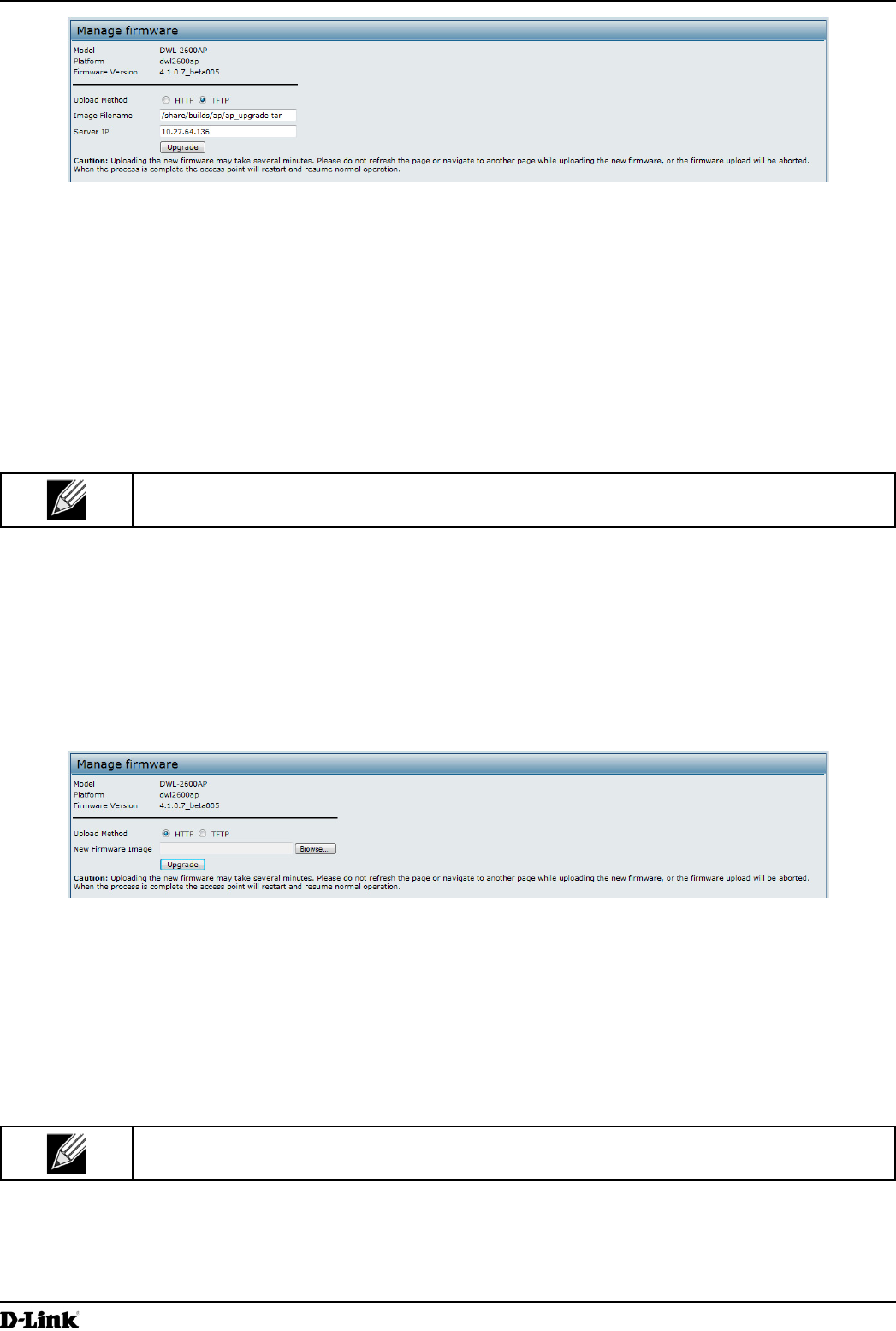
Use the following steps to upgrade the rmware on an access point by using TFTP:
1.) Select TFTP for Upload Method.
Unied Access Point Administrator’s Guide
Unied Access Point Administrator’s Guide
Page 82
March 2012
Section 7 - Maintaining the Access Point
Figure 50 - Manage Firmware (TFTP)
2.) Enter a name (1 to 63 characters) for the image le in the Image Filename eld, including the path to the
directory that contains the image to upload.
For example, to upload the ap_upgrade.tar image located in the /share/builds/ap directory, enter /
share/builds/ap/ap_upgrade.tar in the Image Filename eld.
The rmware upgrade le supplied must be a tar le. Do not attempt to use bin les or les of other formats for
the upgrade; these types of les will not work.
3.) Enter the Server IP address of the TFTP server.
4.) Click Upgrade.
Upon clicking Upgrade for the rmware upgrade, a popup conrmation window is displayed that describes the
upgrade process.
5.) Click OK to conrm the upgrade and start the process.
Note: The rmware upgrade process begins once you click Upgrade and then OK in the pop-up
conrmation window.
The upgrade process may take several minutes during which time the access point will be unavailable. Do not
power down the access point while the upgrade is in process. When the upgrade is complete, the access point
restarts. The AP resumes normal operation with the same conguration settings it had before the upgrade.
6.) To verify that the rmware upgrade completed successfully, check the rmware version shown on the Upgrade
page (or the Basic Settings page). If the upgrade was successful, the updated version name or number is
indicated.
Use the following steps to upgrade the rmware on an access point by using HTTP:
1.) Select HTTP for Upload Method.
Figure 51 - Manage Firmware (HTTP)
2.) If you know the path to the new rmware image le, enter it in the Image Filename eld. Otherwise, click the
Browse button and locate the rmware image le.
The rmware upgrade le supplied must be a tar le. Do not attempt to use bin les or les of other formats for
the upgrade; these types of les will not work.
3.) Click Upgrade to apply the new rmware image.
Upon clicking Upgrade for the rmware upgrade, a popup conrmation window is displayed that describes the
upgrade process.
4.) Click OK to conrm the upgrade and start the process.
Note: The rmware upgrade process begins once you click Upgrade and then OK in the popup
conrmation window.
The upgrade process may take several minutes during which time the access point will be unavailable. Do not
power down the access point while the upgrade is in process. When the upgrade is complete, the access point
restarts. The AP resumes normal operation with the same conguration settings it had before the upgrade.
Unied Access Point Administrator’s Guide
Unied Access Point Administrator’s Guide
Page 83
March 2012
Section 7 - Maintaining the Access Point
5.) To verify that the rmware upgrade completed successfully, check the rmware version shown on the Upgrade
page (or the Basic Settings page). If the upgrade was successful, the updated version name or number is
indicated.
Packet Capture Conguration and Settings
Wireless packet capture operates in two modes:
•) Capture le mode.
•) Remote capture mode.
For capture le mode, captured packets are stored in a le on the Access Point. The AP can transfer the le to a TFTP
server. The le is formatted in pcap format and can be examined using tools such as Wireshark and OmniPeek.
For remote capture mode, the captured packets are redirected in real time to an external PC running the Wireshark®
tool.
The AP can capture the following types of packets:
•) 802.11 packets received and transmitted on radio interfaces. Packets captured on radio interfaces include the
802.11 header.
•) 802.3 packets received and transmitted on the Ethernet interface.
•) 802.3 packets received and transmitted on the internal logical interfaces such as VAPs and WDS interfaces.
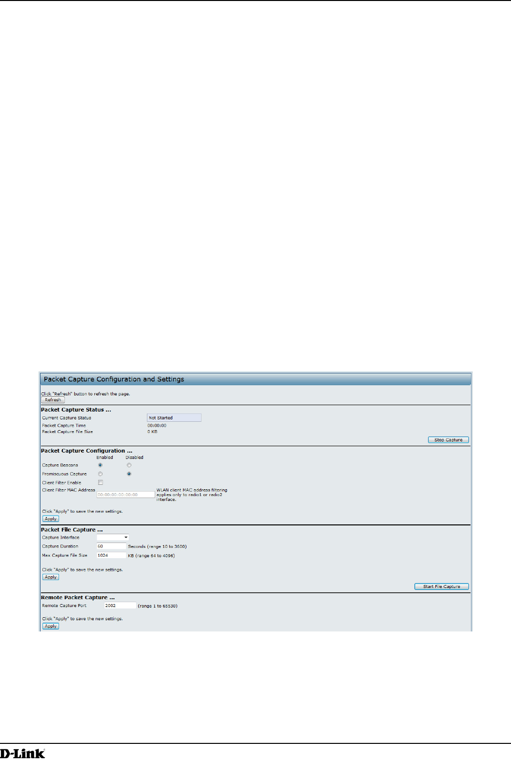
From the Packet Capture Conguration and Settings page, you can:
•) View the current packet capture status.
•) Congure packet capture parameters.
•) Congure packet le capture.
•) Congure a remote capture port.
•) Download a packet capture le.
Figure 52 - Packet Capture Conguration & Settings
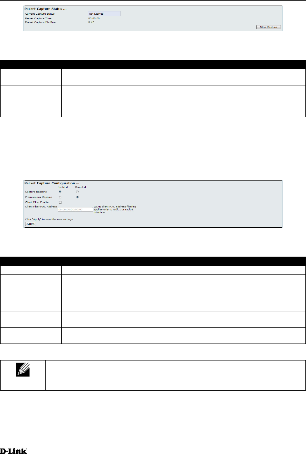
Packet Capture Status
Packet Capture Status allows you to view the status of packet capture on the AP.
Unied Access Point Administrator’s Guide
Unied Access Point Administrator’s Guide
Page 84
March 2012
Section 7 - Maintaining the Access Point
Figure 53 - Packet Capture Status
The following table describes information the packet capture status elds display.
Field Description
Current Capture
Status
Shows whether packet capture is running or stopped.
Packet Capture
Time
Shows elapsed capture time.
Packet Capture File
Size
Shows the current capture le size.
Table 47 - Packet Capture Status
Packet Capture Parameter Conguration
Packet Capture Conguration allows you to congure parameters that affect how packet capture functions on the radio
interfaces.
Figure 54 - Packet Capture Conguration
The following table describes the elds to congure the packet capture.
Field Description
Capture Beacons Enable to capture the 802.11 beacons detected or transmitted by the radio.
Promiscuous
Capture
Enable to place the radio in promiscuous mode when the capture is active.
In promiscuous mode the radio receives all trafc on the channel, including trafc that is not
destined to this AP. While the radio is operating in promiscuous mode, it continues serving
associated clients. Packets not destined to the AP are not forwarded.
As soon as the capture is completed, the radio reverts to non-promiscuous mode operation.
Client Filter Enable Enable to use the WLAN client lter to capture only frames that are transmitted to, or
received from a WLAN client with a specied MAC address.
Client Filter MAC
Address
Specify a MAC address for WLAN client ltering.
Note: The MAC lter is active only when capture is performed on an 802.11 interface.
Table 48 - Packet Capture Conguration
Note: Changes to packet capture conguration parameters take affect after packet capture is
restarted. Modifying the parameters while the packet capture is running doesn’t affect the current
packet capture session. In order to begin using new parameter values, an existing packet capture
session must be stopped and re-started.
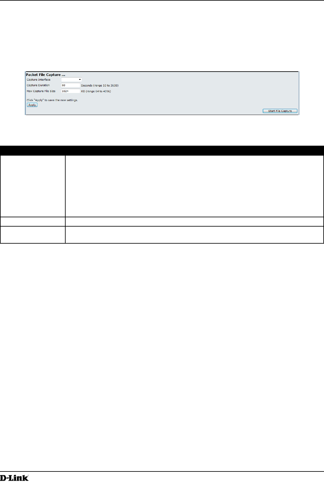
Packet File Capture
In Packet File Capture mode the AP stores captured packets in the RAM le system.
Unied Access Point Administrator’s Guide
Unied Access Point Administrator’s Guide
Page 85
March 2012
Section 7 - Maintaining the Access Point
Upon activation, the packet capture proceeds until one of the following occurs:
•) The capture time reaches congured duration.
•) The capture le reaches its maximum size.
•) The administrator stops the capture.
During the capture, you can monitor the capture status, elapsed capture time, and the current capture le size. This
information can be updated, while the capture is in progress, by clicking Refresh.
Figure 55 - Packet File Capture
The following table describes the elds to congure the packet capture status.
Field Description
Capture Interface Select an AP Capture Interface name from the drop-down menu. AP capture interface
names are eligible for packet capture are:
•) brtrunk - Linux bridge interface in the AP
•) eth0 - 802.3 trafc on the Ethernet port.
•) wlan0 - VAP0 trafc on radio 1.
•) wlan1 - VAP0 trafc on radio 2.
•) radio1 - 802.11 trafc on radio 1.
•) radio2 - 802.11 trafc on radio 2.
Capture Duration Specify the time duration in seconds for the capture (range 10 to 3600).
Max Capture File
Size
Specify the maximum allowed size for the capture le in KB (range 64 to 4096).
Table 49 - Packet File Capture
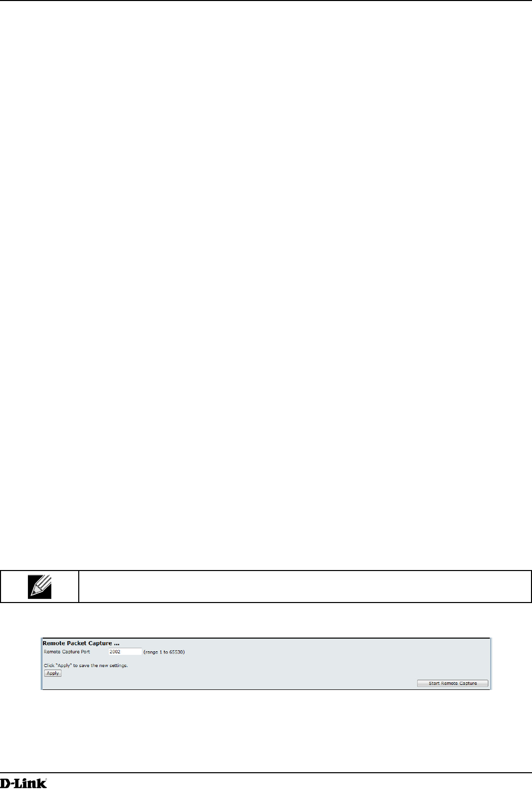
Remote Packet Capture
Remote Packet Capture allows you to specify a remote port as the destination for packet captures. This feature works
in conjunction with the Wireshark network analyzer tool for Windows. A packet capture server runs on the AP and
sends the captured packets via a TCP connection to the Wireshark tool.
A Windows PC running the Wireshark tool allows you to display, log, and analyze captured trafc.
When the remote capture mode is in use, the AP doesn’t store any captured data locally in its le system.
Your can trace up to ve interfaces on the AP at the same time. However, you must start a separate Wireshark session
for each interface. You can congure the IP port number used for connecting Wireshark to the AP. The default port
number is 2002. The system uses 5 consecutive port numbers starting with the congured port for the packet capture
sessions.
If a rewall is installed between the Wireshark PC and the AP, these ports must be allowed to pass through the
rewall. The rewall must also be congured to allow the Wireshark PC to initiate TCP connection to the AP.
To congure Wireshark to use the AP as the source for captured packets, you must specify the remote interface in the
“Capture Options” menu. For example to capture packets on an AP with IP address 192.168.1.10 on radio 1 using the
default IP port, specify the following interface:
rpcap://192.168.1.10/radio1
Unied Access Point Administrator’s Guide
Unied Access Point Administrator’s Guide
Page 86
March 2012
Section 7 - Maintaining the Access Point
To capture packets on the Ethernet interface of the AP and VAP0 on radio 1 using IP port 58000, start two Wireshark
sessions and specify the following interfaces:
rpcap://192.168.1.10:58000/eth0
rpcap://192.168.1.10:58000/wlan0
When you are capturing trafc on the radio interface, you can disable beacon capture, but other 802.11 control frames
are still sent to Wireshark. You can set up a display lter to show only:
•) Data frames in the trace.
•) Trafc on specic BSSIDs.
•) Trafc between two clients.
Some examples of useful display lters are:
•) Exclude beacons and ACK/RTS/CTS frames:
!(wlan.fc.type_subtype == 8 || wlan.fc.type == 1)
•) Data frames only:
wlan.fc.type == 2
•) Trafc on a specic BSSID:
wlan.bssid == 00:02:bc:00:17:d0
•) All trafc to and from a specic client:
wlan.addr == 00:00:e8:4e:5f:8e
In remote capture mode, trafc is sent to the PC running Wireshark via one of the network interfaces. Depending on
where the Wireshark tool is located the trafc can be sent on an Ethernet interface or one of the radios. In order to
avoid a trafc ood caused by tracing the trace packets, the AP automatically installs a capture lter to lter out all
packets destined to the Wireshark application. For example if the Wireshark IP port is congured to be 58000 then the
following capture lter is automatically installed on the AP:
not portrange 58000-58004.
Enabling the packet capture feature impacts performance of the AP and can create a security issue (unauthorized
clients may be able to connect to the AP and trace user data). The AP performance is negatively impacted even if
there is no active Wireshark session with the AP. The performance is negatively impacted to a greater extent when
packet capture is in progress.
Due to performance and security issues, the packet capture mode is not saved in NVRAM on the AP; if the AP resets,
the capture mode is disabled and the you must re-enable it in order to resume capturing trafc. Packet capture
parameters (other than mode) are saved in NVRAM.
In order to minimize performance impact on the AP while trafc capture is in progress, you should install capture lters
to limit which trafc is sent to the Wireshark tool. When capturing 802.11 trafc, large portion of the captured frames
tend to be beacons (typically sent every 100ms by all Access Points). Although Wireshark supports a display lter for
beacon frames, it does not support a capture lter to prevent the AP from forwarding captured beacon packets to the
Wireshark tool. In order to reduce performance impact of capturing the 802.11 beacons, you can disable the capture
beacons mode.
The remote packet capture facility is a standard feature of the Wireshark tool for Windows.
Note: Remote packet capture is not standard on the Linux version of Wireshark; the Linux version
doesn’t work with the AP.
Wireshark is an open source tool and is available for free; it can be downloaded from http://www.wireshark.org.
Figure 56 - Remote Packet Capture
The following table describes the elds to congure the packet capture status.
Unied Access Point Administrator’s Guide
Unied Access Point Administrator’s Guide
Page 87
March 2012
Section 7 - Maintaining the Access Point
Field Description
Remote Capture
Port
Specify the remote port to use as the destination for packet captures. (range 1 to 65530).
Table 50 - Remote Packet Capture
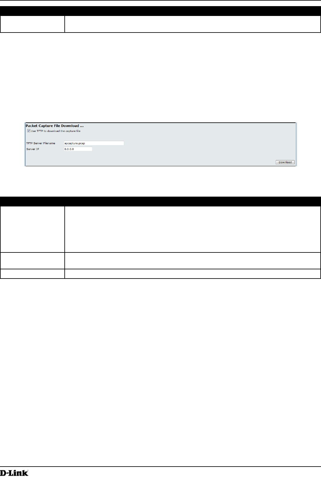
Packet Capture File Download
Packet Capture File Download allows you to download the capture le by TFTP to a congured TFTP server or by
HTTP(S) to a PC. The captured packets are stored in le /tmp/apcapture.pcap on the AP. A capture is automatically
stopped when the capture le download command is triggered.
Because the capture le is located in the RAM le system, it disappears if the AP is reset.
Figure 57 - Packet Capture File Download
The following table describes the elds to congure the packet capture status.
Field Description
Use TFTP to
download the
capture le
Select or clear this option to determine whether to use TFTP or HTTP(S) to download the
capture le:
•) To download the le by using TFTP, select this option and complete the additional
elds.
•) To download the le by using HTTP or HTTPS, clear this option and click Download to
browse to the location where the le is to be saved.
TFTP Server
Filename
When using TFTP to download the le, specify a name for the packet capture le, including
the .pcap le name extension and the path to the directory where you want to save the le.
Server IP When using TFTP to download the le, specify the IP address of the TFTP server.
Table 51 - Packet Capture File Download
Unied Access Point Administrator’s Guide
Unied Access Point Administrator’s Guide
Page 88
March 2012
Section 8 - Conguring Client Quality of Service (QoS)
Section 8 - Conguring Client Quality of Service (QoS)
This section describes how to congure QoS settings that affect trafc from the wireless clients to the AP. By using the
UAP Client QoS features, you can limit bandwidth and apply ACLs and DiffServ policies to the wireless interface. If a
VAP uses WPA Enterprise security to authenticate clients, you can congure the RADIUS server to provide per-client
QoS information.
This section describes the following features:
•) “Conguring VAP QoS Parameters” on page 88
•) “Managing Client QoS ACLs” on page 89
•) “Creating a DiffServ Class Map” on page 95
•) “Creating a DiffServ Policy Map” on page 100
•) “Conguring RADIUS-Assigned Client QoS Parameters” on page 102
Conguring VAP QoS Parameters
The client QoS features on the UAP provide additional control over certain QoS aspects of wireless clients that
connect to the network, such as the amount of bandwidth an individual client is allowed to send and receive. To control
general categories of trafc, such as HTTP trafc or trafc from a specic subnet, you can congure ACLs and assign
them to one or more VAPs.
In addition to controlling general trafc categories, Client QoS allows you to congure per-client conditioning of various
micro-ows through Differentiated Services (DiffServ). DiffServ policies are a useful tool for establishing general micro-
ow denition and treatment characteristics that can be applied to each wireless client, both inbound and outbound,
when it is authenticated on the network.
From the VAP QoS Parameters page, you can enable the Client QoS feature, specify client bandwidth limits, and
select the ACLs and DiffServ policies to use as default values for clients associated with the VAP when the client does
not have their own attributes dened by a RADIUS server.
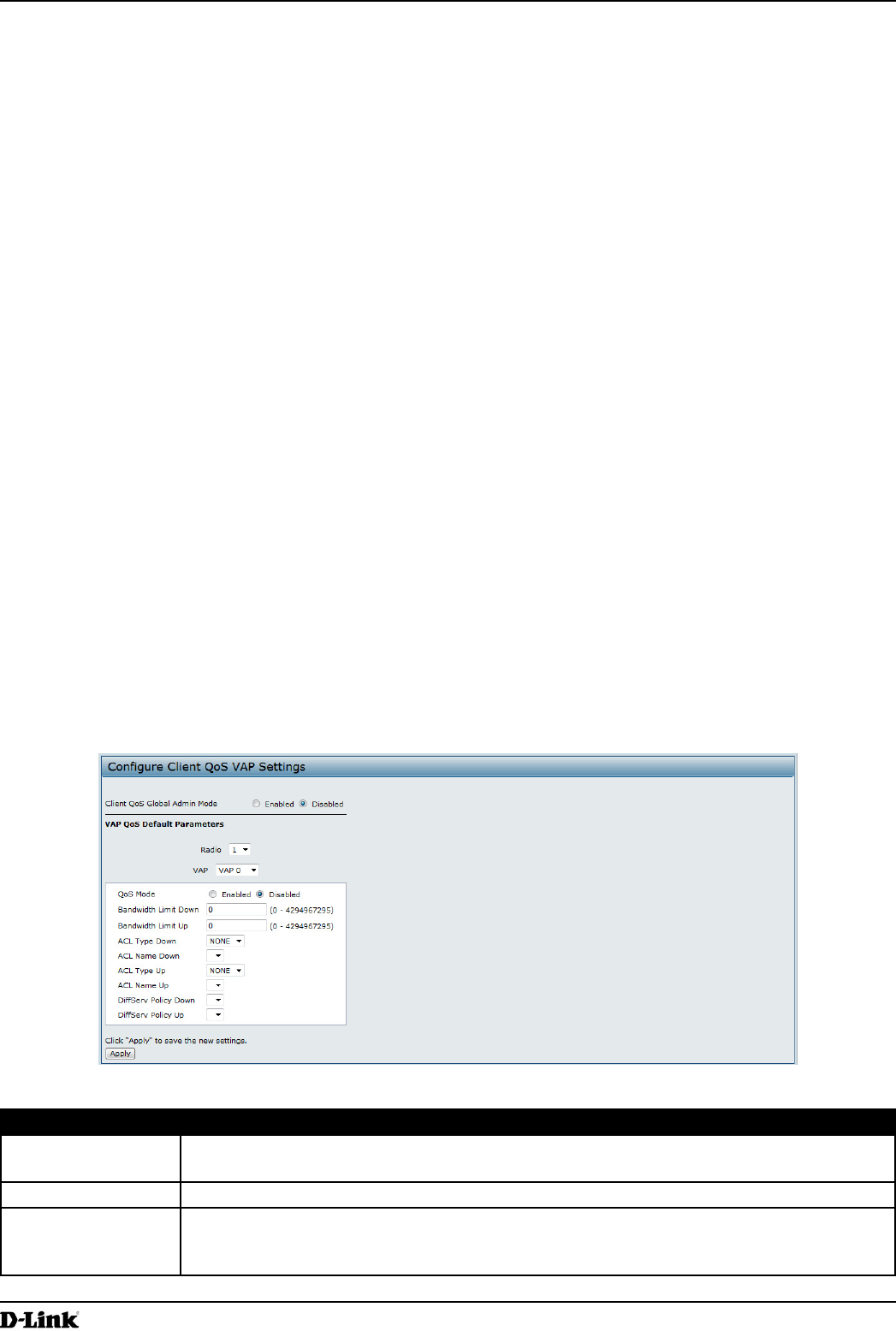
To congure the Client QoS administrative mode and to congure the QoS settings for a VAP, click the VAP QoS
Parameters tab.
Figure 58 - Congure Client QoS VAP Settings
Field Description
Client QoS Global
Admin Mode
Enable or disable Client QoS operation on the AP.
Changing this setting will not affect the WMM settings you congure on the QoS page.
Radio For dual-radio APs, select Radio 1 or Radio 2 to specify which radio to congure.
VAP Specify the VAP that will have the Client QoS settings that you congure.
The QoS settings you congure for the selected VAP will not affect clients that access the
network through other VAPs.

Unied Access Point Administrator’s Guide
Unied Access Point Administrator’s Guide
Page 89
March 2012
Section 8 - Conguring Client Quality of Service (QoS)
Field Description
Client QoS Mode Enable or disable QoS operation on the VAP selected in the VAP menu.
QoS must be enabled globally (from the Client QoS Global Admin Mode eld) and on the
VAP (QoS Mode eld) for the Client QoS settings to be applied to wireless clients.
Bandwidth Limit
Down
Enter the maximum allowed transmission rate from the AP to the wireless client in bits per
second. The valid range is 0 – 429496000 bits/sec.
The value you enter must be a multiple of 8000 bits/sec, in other words, the value must be
n × 8000 bits/sec, where n = 0, 1, 2, 3... If you attempt to set the limit to a value that is not
a multiple of 8000 bits/sec, the conguration will be rejected. A value of 0 means that the
bandwidth maximum limit is not enforced in this direction.
Bandwidth Limit Up Enter the maximum allowed client transmission rate to the AP in bits per second. The valid
range is 0 – 4294967295 bps.
The value you enter must be n × 8000 bits/sec, where n = 0, 1, 2, 3... If you attempt to set
the limit to a value that is not a multiple of 8000 bits/sec, the conguration will be rejected. A
value of 0 means that the bandwidth maximum limit is not enforced in this direction.
ACL Type Down Select the type of ACL to apply to trafc in the outbound (down) direction, which can be one
of the following:
•) IPv4: The ACL examines IPv4 packets for matches to ACL rules
•) IPv6: The ACL examines IPv6 packets for matches to ACL rules
•) MAC: The ACL examines layer 2 frames for matches to ACL rules
ACL Name Down Select the name of the ACL applied to trafc in the outbound (down) direction.
After switching the packet or frame to the outbound interface, the ACL’s rules are checked
for a match. The packet or frame is transmitted if it is permitted, and discarded if it is denied.
ACL Type Up Select the type of ACL to apply to trafc in the inbound (up) direction, which can be one of
the following:
•) IPv4: The ACL examines IPv4 packets for matches to ACL rules
•) IPv6: The ACL examines IPv6 packets for matches to ACL rules
•) MAC: The ACL examines layer 2 frames for matches to ACL rules
ACL Name Up Select the name of the ACL applied to trafc entering the AP in the inbound (up) direction.
When a packet or frame is received by the AP, the ACL’s rules are checked for a match. The
packet or frame is processed if it is permitted, and discarded if it is denied.
DiffServ Policy
Down
Select the name of the DiffServ policy applied to trafc from the AP in the outbound (down)
direction.
DiffServ Policy Up Select the name of the DiffServ policy applied to trafc sent to the AP in the inbound (up)
direction.
Table 52 - VAP QoS Parameters
Managing Client QoS ACLs
ACLs are a collection of permit and deny conditions, called rules, that provide security by blocking unauthorized
users and allowing authorized users to access specic resources. ACLs can block any unwarranted attempts to reach
network resources.
The UAP supports up to 50 IPv4, IPv6, and MAC ACLs.
IPv4 and IPv6 ACLs
IP ACLs classify trafc for Layers 3 and 4.
Each ACL is a set of up to 10 rules applied to trafc sent from a wireless client or to be received by a wireless client.
Each rule species whether the contents of a given eld should be used to permit or deny access to the network.
Rules can be based on various criteria and may apply to one ore more elds within a packet, such as the source or
destination IP address, the source or destination L4 port, or the protocol carried in the packet.
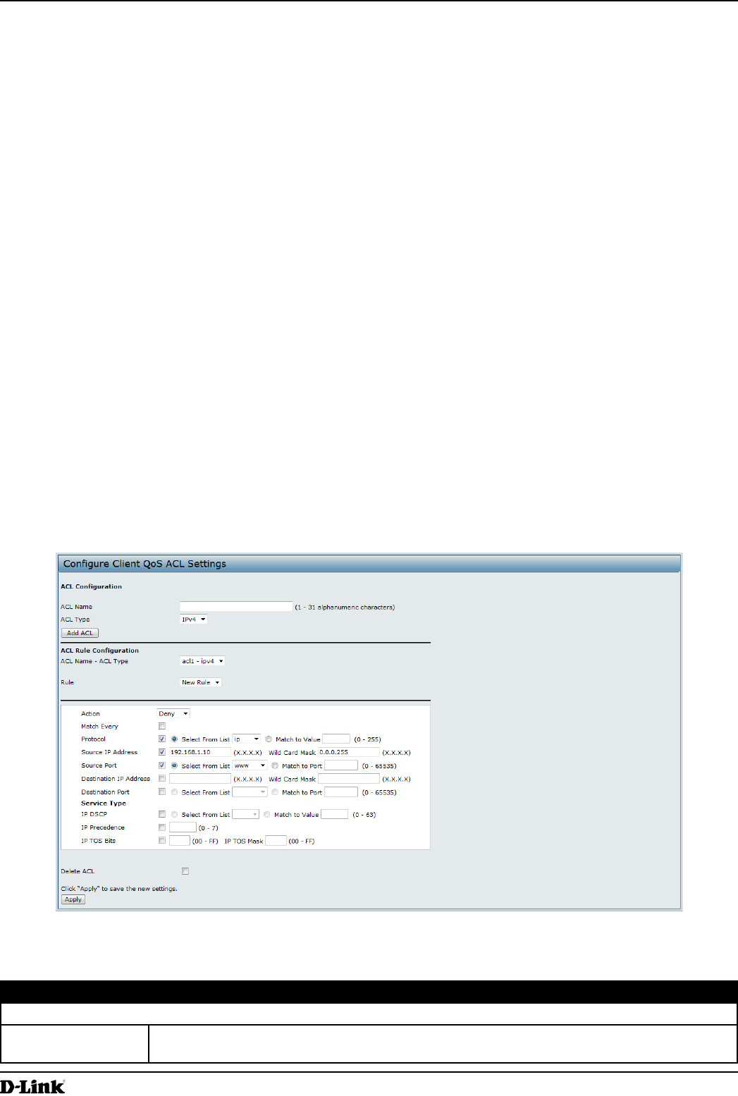
Unied Access Point Administrator’s Guide
Unied Access Point Administrator’s Guide
Page 90
March 2012
Section 8 - Conguring Client Quality of Service (QoS)
MAC ACLs
MAC ACLs are Layer 2 ACLs. You can congure the rules to inspect elds of a frame such as the source or
destination MAC address, the VLAN ID, or the Class of Service 802.1p priority. When a frame enters or exits the AP
port (depending on whether the ACL is applied in the up or down direction), the AP inspects the frame and checks the
ACL rules against the content of the frame. If any of the rules match the content, a permit or deny action is taken on
the frame.
ACL Conguration Process
Congure ACLs and rules on the Client QoS ACL page (steps 1–5), and then apply the rules to a specied VAP on
the AP QoS Parameters page (step 6).
Use the following general steps to congure ACLs:
1.) Specify a name for the ACL.
2.) Select the type of ACL to add.
3.) Add the ACL.
4.) Add new rules to the ACL.
5.) Congure the match criteria for the rules.
6.) Apply the ACL to one or more VAPs.
For an example of how to congure an ACL, see “ACL Conguration Process” on page 90.
To congure an ACL, click the Client QoS ACL tab.
The elds to congure ACL rules appear only after you have created an ACL. The following image shows the
conguration of a new rule for the IPv4 ACL named acl1. The rule prevents HTTP trafc from all clients in the
192.168.20.0 network from being forwarded.
Figure 59 - Congure Client QoS ACL Settings
The following table describes the elds available on the Client QoS ACL page.
Field Description
ACL Conguration
ACL Name Enter a name to identify the ACL. The name can contain from 1 – 31 alphanumeric
characters. Spaces are not allowed.