D Link WL2600APA1 802.11n Single-band Unified Access Point User Manual Part 3
D Link Corporation 802.11n Single-band Unified Access Point Part 3
D Link >
Contents
- 1. User Manual Part 1
- 2. User Manual Part 2
- 3. User Manual Part 3
User Manual Part 3

Unied Access Point Administrator’s Guide
Unied Access Point Administrator’s Guide
Page 91
March 2012
Section 8 - Conguring Client Quality of Service (QoS)
Field Description
ACL Type Select the type of ACL to congure:
•) IPv4
•) IPv6
•) MAC
IPv4 and IPv6 ACLs control access to network resources based on Layer 3 and Layer 4
criteria. MAC ACLs control access based on Layer 2 criteria.
ACL Rule Conguration
ACL Name - ACL
Type
Select the ACL to congure with the new rule. The list contains all ACLs added in the ACL
Conguration section.
Rule To congure a new rule to add to the selected ACL, select New Rule. To add an existing rule
to an ACL or to modify a rule, select the rule number.
When an ACL has multiple rules, the rules are applied to the packet or frame in the order in
which you add them to the ACL. There is an implicit deny all rule as the nal rule.
Action Species whether the ACL rule permits or denies an action.
•) When you select Permit, the rule allows all trafc that meets the rule criteria to enter or
exit the AP (depending on the ACL direction you select). Trafc that does not meet the
criteria is dropped.
•) When you select Deny, the rule blocks all trafc that meets the rule criteria from
entering or exiting the AP (depending on the ACL direction you select). Trafc that
does not meet the criteria is forwarded unless this rule is the nal rule. Because there
is an implicit deny all rule at the end of every ACL, trafc that is not explicitly permitted
is dropped.
Match Every Indicates that the rule, which either has a permit or deny action, will match the frame or
packet regardless of its contents.
If you select this eld, you cannot congure any additional match criteria. The Match Every
option is selected by default for a new rule. You must clear the option to congure other
match elds.
IPv4 ACL
Protocol Select the Protocol eld to use an L3 or L4 protocol match condition based on the value of
the IP Protocol eld in IPv4 packets or the Next Header eld of IPv6 packets.
Once you select the eld, choose the protocol to match by keyword or enter a protocol ID.
Select From List
Select one of the following protocols from the list:
•) IP
•) ICMP
•) IGMP
•) TCP
•) UDP
Match to Value
To match a protocol that is not listed by name, enter the protocol ID.
The protocol ID is a standard value assigned by the IANA. The range is a number from
0–255.
Source IP Address Select this eld to require a packet’s source IP address to match the address listed here.
Enter an IP address in the appropriate eld to apply this criteria.
Wild Card Mask Species the source IP address wildcard mask.
The wild card masks determines which bits are used and which bits are ignored. A wild card
mask of 255.255.255.255 indicates that no bit is important. A wildcard of 0.0.0.0 indicates
that all of the bits are important. This eld is required when Source IP Address is checked.
A wild card mask is, in essence, the inverse of a subnet mask. For example, To match the
criteria to a single host address, use a wildcard mask of 0.0.0.0. To match the criteria to a
24-bit subnet (for example 192.168.10.0/24), use a wild card mask of 0.0.0.255.

Unied Access Point Administrator’s Guide
Unied Access Point Administrator’s Guide
Page 92
March 2012
Section 8 - Conguring Client Quality of Service (QoS)
Field Description
Source Port Select this eld to include a source port in the match condition for the rule. The source port
is identied in the datagram header.
Once you select the eld, choose the port name or enter the port number.
Select From List
Select the keyword associated with the source port to match:
•) ftp
•) ftpdata
•) http
•) smtp
•) snmp
•) telnet
•) tftp
•) www
Each of these keywords translates into its equivalent port number.
Match to Port
Enter the IANA port number to match to the source port identied in the datagram header.
The port range is 0 – 65535 and includes three different types of ports:
•) 0 – 1023: Well Known Ports
•) 1024 – 49151: Registered Ports
•) 49152 – 65535: Dynamic and/or Private Ports
Destination IP
Address
Select this eld to require a packet’s destination IP address to match the address listed
here. Enter an IP address in the appropriate eld to apply this criteria.
Wild Card Mask Species the destination IP address wildcard mask.
The wild card masks determines which bits are used and which bits are ignored. A wild card
mask of 255.255.255.255 indicates that no bit is important. A wildcard of 0.0.0.0 indicates
that all of the bits are important. This eld is required when Source IP Address is checked.
A wild card mask is in essence the inverse of a subnet mask. For example, To match the
criteria to a single host address, use a wildcard mask of 0.0.0.0. To match the criteria to a
24-bit subnet (for example 192.168.10.0/24), use a wild card mask of 0.0.0.255.
Destination Port Select this eld to include a destination port in the match condition for the rule. The
destination port is identied in the datagram header.
Once you select the eld, choose the port name or enter the port number.
Select From List
Select the keyword associated with the destination port to match:
•) ftp
•) ftpdata
•) http
•) smtp
•) snmp
•) telnet
•) tftp
•) www
Each of these keywords translates into its equivalent port number.
Match to Port
Enter the IANA port number to match to the destination port identied in the datagram
header. The port range is 0 – 65535 and includes three different types of ports:
•) 0 – 1023: Well Known Ports
•) 1024 – 49151: Registered Ports
•) 49152 – 65535: Dynamic and/or Private Ports
IP DSCP To use IP DSCP as a match criteria, select the check box and select a DSCP value
keyword or enter a DSCP value to match. You can select only one service type (DSCP, IP
Precedence or TOS bits) to use for match criteria.
Select from List
Select from a list of DSCP types.
Match to Value
Enter a DSCP Value to match (0 – 63).

Unied Access Point Administrator’s Guide
Unied Access Point Administrator’s Guide
Page 93
March 2012
Section 8 - Conguring Client Quality of Service (QoS)
Field Description
IP Precedence Select this option and enter a value to use the packet’s IP Precedence value in the IP
header as match criteria. You can select only one service type (DSCP, IP Precedence or
TOS bits) to use for match criteria.
The IP Precedence range is 0 – 7.
IP TOS Bits Select this option and enter a value to use the packet’s Type of Service bits in the IP header
as match criteria. You can select only one service type (DSCP, IP Precedence or TOS bits)
to use for match criteria.
The IP TOS eld in a packet is dened as all eight bits of the Service Type octet in the IP
header. The TOS Bits value is a two-digit hexadecimal number from 00 to ff.
The high-order three bits represent the IP precedence value. The high-order six bits
represent the IP Differentiated Services Code Point (DSCP) value.
IP TOS Mask Enter an IP TOS mask value to identify the bit positions in the TOS Bits value that are used
for comparison against the IP TOS eld in a packet.
The TOS Mask value is a two-digit hexadecimal number from 00 to ff, representing an
inverted (i.e. wildcard) mask. The zero-valued bits in the TOS Mask denote the bit positions
in the TOS Bits value that are used for comparison against the IP TOS eld of a packet. For
example, to check for an IP TOS value having bits 7 and 5 set and bit 1 clear, where bit 7
is most signicant, use a TOS Bits value of a0 and a TOS Mask of 00. This is an optional
conguration.
IPv6 ACL
Protocol Select the Protocol eld to use an L3 or L4 protocol match condition based on the value of
the IP Protocol eld in IPv4 packets or the Next Header eld of IPv6 packets.
Once you select the eld, choose the protocol to match by keyword or enter a protocol ID.
Select From List
Select one of the following protocols from the list:
•) IP
•) ICMP
•) IPv6
•) ICMPv6
•) IGMP
•) TCP
•) UDP
Match to Value
To match a protocol that is not listed by name, enter the protocol ID.
The protocol ID is a standard value assigned by the IANA. The range is a number from
0–255.
Source IPv6
Address
Select this eld to require a packet’s source IPv6 address to match the address listed here.
Enter an IPv6 address in the appropriate eld to apply this criteria.
Source IPv6 Prex
Length
Enter the prex length of the source IPv6 address.

Unied Access Point Administrator’s Guide
Unied Access Point Administrator’s Guide
Page 94
March 2012
Section 8 - Conguring Client Quality of Service (QoS)
Field Description
Source Port Select this option to include a source port in the match condition for the rule. The source port
is identied in the datagram header.
Once you select the eld, choose the port name or enter the port number.
Select From List
Select the keyword associated with the source port to match:
•) ftp
•) ftpdata
•) http
•) smtp
•) snmp
•) telnet
•) tftp
•) www
Each of these keywords translates into its equivalent port number.
Match to Port
Enter the IANA port number to match to the source port identied in the datagram header.
The port range is 0 – 65535 and includes three different types of ports:
•) 0 – 1023: Well Known Ports
•) 1024 – 49151: Registered Ports
•) 49152 – 65535: Dynamic and/or Private Ports
Destination IPv6
Address
Select this eld to require a packet’s destination IPv6 address to match the address listed
here. Enter an IPv6 address in the appropriate eld to apply this criteria.
Destination IPv6
Prex Length
Enter the prex length of the destination IPv6 address.
Destination Port Select this option to include a destination port in the match condition for the rule. The
destination port is identied in the datagram header.
Once you select the eld, choose the port name or enter the port number.
Select From List
Select the keyword associated with the destination port to match:
•) ftp
•) ftpdata
•) http
•) smtp
•) snmp
•) telnet
•) tftp
•) www
Each of these keywords translates into its equivalent port number.
Match to Port
Enter the IANA port number to match to the destination port identied in the datagram
header. The port range is 0 – 65535 and includes three different types of ports:
•) 0 – 1023: Well Known Ports
•) 1024 – 49151: Registered Ports
•) 49152 – 65535: Dynamic and/or Private Ports
IPv6 Flow Label Flow label is 20-bit number that is unique to an IPv6 packet. It is used by end stations to
signify quality-of-service handling in routers (range 0 to 1048575).
IPv6 DSCP To use IPv6 DSCP as a match criteria, select the check box and select a DSCP value
keyword or enter a DSCP value to match. You can select only one service type (DSCP, IP
Precedence or TOS bits) to use for match criteria.
Select from List
Select from a list of DSCP types.
Match to Value
Enter a DSCP Value to match (0 – 63).
MAC ACL
Unied Access Point Administrator’s Guide
Unied Access Point Administrator’s Guide
Page 95
March 2012
Section 8 - Conguring Client Quality of Service (QoS)
Field Description
EtherType Select the EtherType eld to compare the match criteria against the value in the header of
an Ethernet frame.
Select an EtherType keyword or enter an EtherType value to specify the match criteria.
Select from List Select
Select one of the following protocol types:
•) appletalk
•) arp
•) ipv4
•) ipv6
•) ipx
•) netbios
•) pppoe
Match to Value
Enter a custom protocol identier to which packets are matched. The value is a four-digit
hexadecimal number in the range of 0600 – FFFF.
Class of Service Select this eld and enter an 802.1p user priority to compare against an Ethernet frame.
The valid range is 0 – 7. This eld is located in the rst/only 802.1Q VLAN tag.
Source MAC
Address
Select this eld and enter the source MAC address to compare against an Ethernet frame.
Source MAC Mask Select this eld and enter the source MAC address mask specifying which bits in the source
MAC to compare against an Ethernet frame.
A 0 indicates that the address bit is signicant, and an f indicates that the address bit is to be
ignored. A MAC mask of 00:00:00:00:00:00 matches a single MAC address.
Destination MAC
Address
Select this eld and enter the destination MAC address to compare against an Ethernet
frame.
Destination MAC
Mask
Enter the destination MAC address mask specifying which bits in the destination MAC to
compare against an Ethernet frame.
A 0 indicates that the address bit is signicant, and an f indicates that the address bit is to be
ignored. A MAC mask of 00:00:00:00:00:00 matches a single MAC address.
VLAN ID Select this eld and enter the VLAN IDs to compare against an Ethernet frame.
This eld is located in the rst/only 802.1Q VLAN tag.
Table 53 - ACL Conguration
After you set the desired rule criteria, click Apply. To delete an ACL, select the Delete ACL option and click Apply.
Creating a DiffServ Class Map
The Client QoS feature contains Differentiated Services (DiffServ) support that allows trafc to be classied into
streams and given certain QoS treatment in accordance with dened per-hop behaviours.
Standard IP-based networks are designed to provide best effort data delivery service. Best effort service implies that
the network delivers the data in a timely fashion, although there is no guarantee that it will. During times of congestion,
packets may be delayed, sent sporadically, or dropped. For typical Internet applications, such as e-mail and le
transfer, a slight degradation in service is acceptable and in many cases unnoticeable. However, on applications with
strict timing requirements, such as voice or multimedia, any degradation of service has undesirable effects.
By classifying the trafc and creating policies that dene how to handle these trafc classes, you can make sure that
time-sensitive trafc is given precedence over other trafc.
The UAP supports up to 50 Class Maps.
Unied Access Point Administrator’s Guide
Unied Access Point Administrator’s Guide
Page 96
March 2012
Section 8 - Conguring Client Quality of Service (QoS)
Dening DiffServ
To use DiffServ for Client QoS, use the Class Map and Policy Map pages to dene the following categories and their
criteria:
•) Class: create classes and dene class criteria
•) Policy: create policies, associate classes with policies, and dene policy statements
Once you dene the class and associate it with a policy, apply the policy to a specied VAP on the VAP QoS
Parameters page.
Packets are classied and processed based on dened criteria. The classication criteria is dened by a class. The
processing is dened by a policy’s attributes. Policy attributes may be dened on a per-class instance basis, and it is
these attributes that are applied when a match occurs. A policy can contain multiple classes. When the policy is active,
the actions taken depend on which class matches the packet.
Packet processing begins by testing the class match criteria for a packet. A policy is applied to a packet when a class
match within that policy is found. DiffServ is supported for IPv4 and IPv6 packets.
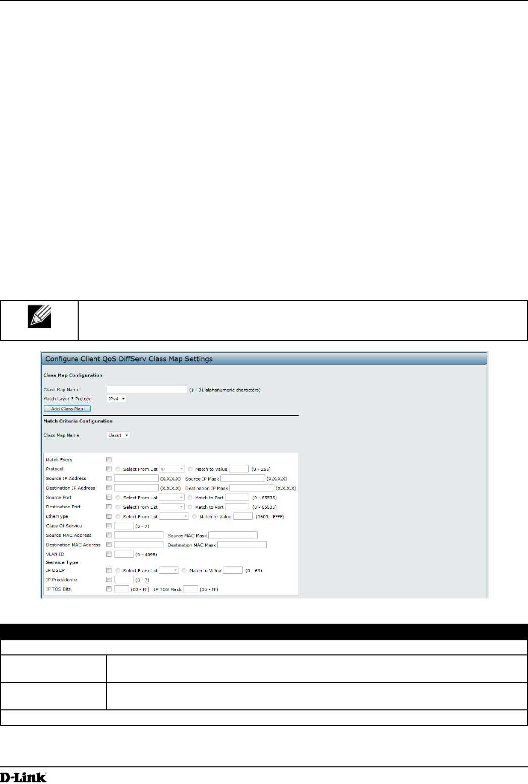
Use the Class Map page to add a new Diffserv class name, or to rename or delete an existing class, and dene the
criteria to associate with the DiffServ class.
To congure a DiffServ Class Map, click the Class Map tab.
Note: The Class Map page displays the Match Criteria Conguration elds only if a Class Map
has been created. To create a Class Map, enter a name in the Class Map Name eld and click
Add Class Map.
Figure 60 - Congure Client QoS DiffServ Class Map Settings
Field Description
Class Map Conguration
Class Map Name Enter a Class Map Name to add. The name can range from 1 to 31 alphanumeric
characters.
Match Layer 3
Protocol
Specify whether to classify IPv4 or IPv6 packets.
Match Criteria Conguration

Unied Access Point Administrator’s Guide
Unied Access Point Administrator’s Guide
Page 97
March 2012
Section 8 - Conguring Client Quality of Service (QoS)
Field Description
Class Map Name Select name of the class to congure.
Use the elds in the Match Criteria Conguration area to match packets to a class. Select
the check box for each eld to be used as a criterion for a class and enter data in the related
eld. You can have multiple match criteria in a class.
Note: The match criteria elds that are available depend on whether the class map is an
IPv4 or IPv6 class map.
Match Every Select Match Every to specify that the match condition is true to all the parameters in an L3
packet.
All L3 packets will match an Match Every match condition.
Protocol Select the Protocol eld to use an L3 or L4 protocol match condition based on the value of
the IP Protocol eld in IPv4 packets or the Next Header eld of IPv6 packets.
Once you select the eld, choose the protocol to match by keyword or enter a protocol ID.
Select From List
Select one of the following protocols from the list:
•) IP
•) ICMP
•) IPv6
•) ICMPv6
•) IGMP
•) TCP
•) UDP
Match to Value
To match a protocol that is not listed by name, enter the protocol ID.
The protocol ID is a standard value assigned by the IANA. The range is a number from 0 –
255.
IPv4 Class Maps
Source IP Address Select this eld to require a packet’s source IP address to match the address listed here.
Enter an IP address in the appropriate eld to apply this criteria.
Source IP Mask Enter the source IP address mask.
The mask for DiffServ is a network-style bit mask in IP dotted decimal format indicating
which part(s) of the destination IP Address to use for matching against packet content.
A DiffServ mask of 255.255.255.255 indicates that all bits are important, and a mask of
0.0.0.0 indicates that no bits are important. The opposite is true with an ACL wild card
mask. For example, to match the criteria to a single host address, use a DiffServ mask of
255.255.255.255. To match the criteria to a 24-bit subnet (for example 192.168.10.0/24), use
a mask of 255.255.255.0.
Destination IP
Address
Select this eld to require a packet’s destination IP address to match the address listed
here. Enter an IP address in the appropriate eld to apply this criteria.
Destination IP Mask Enter the destination IP address mask.
The mask for DiffServ is a network-style bit mask in IP dotted decimal format indicating
which part(s) of the destination IP Address to use for matching against packet content.
A DiffServ mask of 255.255.255.255 indicates that all bits are important, and a mask of
0.0.0.0 indicates that no bits are important. The opposite is true with an ACL wild card
mask. For example, to match the criteria to a single host address, use a DiffServ mask of
255.255.255.255. To match the criteria to a 24-bit subnet (for example 192.168.10.0/24), use
a mask of 255.255.255.0.
IPv6 Class Maps
Source IPv6
Address
Select this eld to require a packet’s source IPv6 address to match the address listed here.
Enter an IPv6 address in the appropriate eld to apply this criteria.
Source IPv6 Prex
Length
Enter the prex length of the source IPv6 address.
Destination IPv6
Address
Select this eld to require a packet’s destination IPv6 address to match the address listed
here. Enter an IPv6 address in the appropriate eld to apply this criteria.
Destination IPv6
Prex Length
Enter the prex length of the destination IPv6 address.
IPv6 Flow Label Flow label is 20-bit number that is unique to an IPv6 packet. It is used by end stations to
signify quality-of-service handling in routers (range 0 to 1048575).

Unied Access Point Administrator’s Guide
Unied Access Point Administrator’s Guide
Page 98
March 2012
Section 8 - Conguring Client Quality of Service (QoS)
Field Description
IP DSCP To use IP DSCP as a match criteria, select the check box and select a DSCP value keyword
or enter a DSCP.
Select from List
Select from a list of DSCP types.
Match to Value
Enter a DSCP Value to match (0 – 63).
IPv4 and IPv6 Class Maps
Source Port Select this eld to include a source port in the match condition for the rule. The source port
is identied in the datagram header.
Once you select the eld, choose the port name or enter the port number.
Select From List
Select the keyword associated with the source port to match:
•) ftp
•) ftpdata
•) http
•) smtp
•) snmp
•) telnet
•) tftp
•) www
Each of these keywords translates into its equivalent port number.
Match to Port
Enter the IANA port number to match to the source port identied in the datagram header.
The port range is 0 – 65535 and includes three different types of ports:
•) 0 – 1023: Well Known Ports
•) 1024 – 49151: Registered Ports
•) 49152 – 65535: Dynamic and/or Private Ports
Destination Port Select this eld to include a destination port in the match condition for the rule. The
destination port is identied in the datagram header.
Once you select the eld, choose the port name or enter the port number.
Select From List
Select the keyword associated with the destination port to match:
•) ftp
•) ftpdata
•) http
•) smtp
•) snmp
•) telnet
•) tftp
•) www
Each of these keywords translates into its equivalent port number.
Match to Port
Enter the IANA port number to match to the destination port identied in the datagram
header. The port range is 0 – 65535 and includes three different types of ports:
•) 0 – 1023: Well Known Ports
•) 1024 – 49151: Registered Ports
•) 49152 – 65535: Dynamic and/or Private Ports

Unied Access Point Administrator’s Guide
Unied Access Point Administrator’s Guide
Page 99
March 2012
Section 8 - Conguring Client Quality of Service (QoS)
Field Description
EtherType Select the EtherType eld to compare the match criteria against the value in the header of
an Ethernet frame.
Select an EtherType keyword or enter an EtherType value to specify the match criteria.
Select from List Select
Select one of the following protocol types:
•) appletalk
•) arp
•) ipv4
•) ipv6
•) ipx
•) netbios
•) pppoe
Match to Value
Enter a custom protocol identier to which packets are matched. The value is a four-digit
hexidecimal number in the range of 0600 – FFFF.
Class of Service Select the eld and enter a class of service 802.1p user priority value to be matched for the
packets. The valid range is 0 – 7.
Source MAC
Address
Select this eld and enter the source MAC address to compare against an Ethernet frame.
Source MAC Mask Enter the source MAC address mask specifying which bits in the destination MAC to
compare against an Ethernet frame.
An f indicates that the address bit is signicant, and a 0 indicates that the address bit is to be
ignored. A MAC mask of ff:ff:ff:ff:ff:ff matches a single MAC address.
Destination MAC
Address
Select this eld and enter the destination MAC address to compare against an Ethernet
frame.
Destination MAC
Mask
Enter the destination MAC address mask specifying which bits in the destination MAC to
compare against an Ethernet frame.
An f indicates that the address bit is signicant, and a 0 indicates that the address bit is to be
ignored. A MAC mask of ff:ff:ff:ff:ff:ff matches a single MAC address.
VLAN ID Select the eld and enter a VLAN ID to be matched for packets. The VLAN ID range is 0 –
4095.
IPv4 Class Maps
Service Type You can specify one type of service to use in matching packets to class criteria.
IP DSCP To use IP DSCP as a match criteria, select the check box and select a DSCP value keyword
or enter a DSCP.
Select from List
Select from a list of DSCP types.
Match to Value
Enter a DSCP Value to match (0 – 63).
IP Precedence Select this eld to match the packet’s IP Precedence value to the class criteria IP
Precedence value.
The IP Precedence range is 0 – 7.
IP TOS Bits Select this eld and enter a value to use the packet’s Type of Service bits in the IP header
as match criteria.
The TOS bit value ranges between (00 – FF). The high-order three bits represent the IP
precedence value. The high-order six bits represent the IP Differentiated Services Code
Point (DSCP) value.
IP TOS Mask Enter an IP TOS mask value to perform a boolean AND with the TOS eld in the header of
the packet and compared against the TOS entered for this rule.
The TOS Mask can be used to compare specic bits (Precedence/Type of Service) from the
TOS eld in the IP header of a packet against the TOS value entered for this rule. (00 – FF).
Delete Class Map Check to delete the class map selected in the Class Map Name menu. The class map
cannot be deleted if it is already attached to a policy.
Table 54 - DiffServ Class Map
To delete a Class Map, select the Delete Class Map option and click Apply.
Unied Access Point Administrator’s Guide
Unied Access Point Administrator’s Guide
Page 100
March 2012
Section 8 - Conguring Client Quality of Service (QoS)
Creating a DiffServ Policy Map
Use the Policy Map page to create DiffServ policies and to associate a collection of classes with one or more policy
statements.
The UAP supports up to 50 Policy Maps.
Packets are classied and processed based on dened criteria. The classication criteria is dened by a class on the
Class Map page. The processing is dened by a policy’s attributes on the Policy Map page. Policy attributes may be
dened on a per-class instance basis, and it is these attributes that are applied when a match occurs. A Policy Map
can contain up to 10 Class Maps. When the policy is active, the actions taken depend on which class matches the
packet.
Packet processing begins by testing the class match criteria for a packet. A policy is applied to a packet when a class
match within that policy is found.
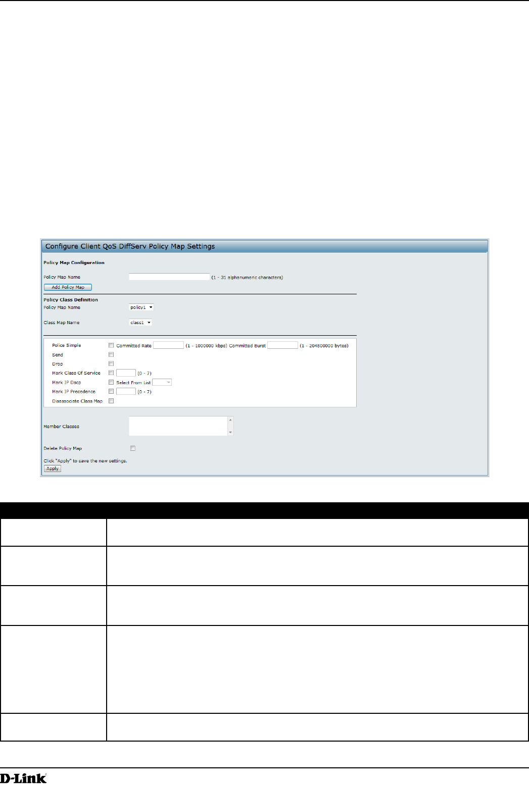
To create a DiffServ policy, click the Policy Map tab.
Figure 61 - Congure Client QoS DiffServ Policy Map Settings
Field Description
Policy Map Name Enter then name of the policy map to add. The name can contain up to 31 alphanumeric
characters.
Policy Map Name
(Policy Class
Denition)
Select the policy to associate with a member class.
Class Map Name
(Policy Class
Denition)
Select the member class to associate with this policy name.
Police Simple Select this option to establish the trafc policing style for the class. The simple form of the
policing style uses a single data rate and burst size, resulting in two outcomes: conform and
non-conform.
Committed Rate
Enter the committed rate, in Kbps, to which trafc must conform.
Committed Burst
Enter the committed burst size, in bytes, to which trafc must conform.
Send Select Send to specify that all packets for the associated trafc stream are to be forwarded if
the class map criteria is met.
Unied Access Point Administrator’s Guide
Unied Access Point Administrator’s Guide
Page 101
March 2012
Section 8 - Conguring Client Quality of Service (QoS)
Field Description
Drop Select Drop to specify that all packets for the associated trafc stream are to be dropped if
the class map criteria is met.
Mark Class of
Service
Select this eld to mark all packets for the associated trafc stream with the specied class
of service value in the priority eld of the 802.1p header. If the packet does not already
contain this header, one is inserted. The CoS value is an integer from 0 – 7.
Mark IP DSCP Select this eld to mark all packets for the associated trafc stream with the IP DSCP value
you select from the list or specify.
Select from List
Select from a list of DSCP types.
Match to Value
Enter a DSCP Value to match (0 – 63).
Mark IP Precedence Select this eld to mark all packets for the associated trafc stream with the specied IP
Precedence value. The IP Precedence value is an integer from 0 – 7.
Disassociate Class
Map
Select this option and click Apply to remove the class selected in the Class Map Name
menu from the policy selected in the Policy Map Name menu.
Member Classes Lists all DiffServ classes currently dened as members of the selected policy. If no class is
associated with the policy, the eld is empty.
Delete Policy Map Select this eld to delete the policy map showing in the Policy Map Name menu.
Table 55 - DiffServ Policy Map
To delete a Policy Map, select the Delete Policy Map option and click Apply.
Client QoS Status
The Client QoS Status page shows the client QoS settings that are applied to each client currently associated with
the AP.
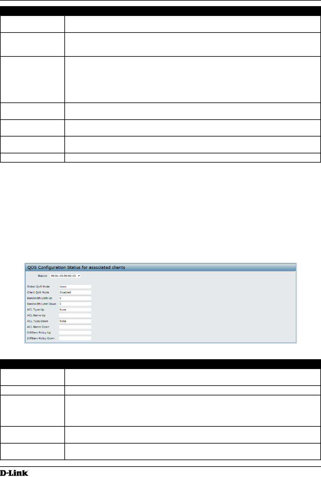
To view QoS settings for an associated client, click the Client QoS Status tab.
Figure 62 - QoS Conguration Status For Associated Clients
Field Description
Station The Station menu contains the MAC address of each client currently associated with the AP.
To view the QoS settings applied to a client, select its MAC address from the list.
Global QoS Mode Shows the current Client QoS Global Admin Mode on the AP.
Client QoS Mode Shows whether the QOS mode for the selected client is enabled or disabled.
Note: For the Qos Mode to be enabled on a client, it must be globally enabled on the AP
and enabled on the VAP the client is associated with. Use the VAP QoS Parameters page
to enable the QoS Global Admin mode and the per-VAP QoS Mode.
Bandwidth Limit Up Shows the maximum allowed transmission rate from the client to the AP in bits per second
(bps). The valid range is 0 – 4294967295 bps.
Bandwidth Limit
Down
Shows the maximum allowed transmission rate from the AP to the client in bits per second
(bps). The valid range is 0 – 4294967295 bps.
Unied Access Point Administrator’s Guide
Unied Access Point Administrator’s Guide
Page 102
March 2012
Section 8 - Conguring Client Quality of Service (QoS)
Field Description
ACL Type Up Shows the type of ACL that is applied to trafc in the inbound (client-to-AP) direction, which
can be one of the following:
•) IPv4: The ACL examines IPv4 packets for matches to ACL rules.
•) IPv6: The ACL examines IPv6 packets for matches to ACL rules.
•) MAC: The ACL examines layer 2 frames for matches to ACL rules.
ACL Name Up Shows the name of the ACL applied to trafc entering the AP in the inbound direction.
When a packet or frame is received by the AP, the ACL’s rules are checked for a match. The
packet or frame is processed if it is permitted and discarded if it is denied.
ACL Type Down Shows the type of ACL to apply to trafc in the outbound (AP-to-client) direction, which can
be one of the following:
•) IPv4: The ACL examines IPv4 packets for matches to ACL rules.
•) IPv6: The ACL examines IPv6 packets for matches to ACL rules
•) MAC: The ACL examines layer 2 frames for matches to ACL rules
ACL Name Down Shows the name of the ACL applied to trafc in the outbound direction.
After switching the packet or frame to the outbound interface, the ACL’s rules are checked
for a match. The packet or frame is transmitted if it is permitted and discarded if it is denied.
DiffServ Policy Up Shows the name of the DiffServ policy applied to trafc sent to the AP in the inbound (client-
to-AP) direction.
DiffServ Policy
Down
Shows the name of the DiffServ policy applied to trafc from the AP in the outbound (AP-to-
client) direction.
Table 56 - Client QoS Status
Conguring RADIUS-Assigned Client QoS Parameters
If a VAP is congured to use WPA Enterprise security, you can include client QoS information in the client database
on the RADIUS server. When a client successfully authenticates, the RADIUS server can include bandwidth limits and
identify the ACLs and DiffServ policies to apply to the specic wireless client. ACLs and DiffServ policies referenced
in the RADIUS client database must match the names of the ACLs and DiffServ policies congured on the AP to be
successfully applied to the wireless clients.
The following table describes the QoS attributes that can be included in the client’s RADIUS server entry. If a wireless
client successfully authenticates using WPA Enterprise, each QoS RADIUS attribute that exists for the client is sent
to the AP for processing. The attributes are optional and do not need to be present in the client entry. If the attribute is
not present, the Client QoS setting on the AP is used.
RADIUS
Attribute
ID Description Type/Range
Vendor-Specic (26),
WISPr-Bandwidth-
Max-Down
14122,8 Maximum allowed client reception rate from the AP in bits per
second. If nonzero, the specied value is rounded down to the
nearest 64 Kbps value when used in the AP (64 Kbps minimum).
If zero, bandwidth limiting is not enforced for the client in this
direction.
Type: integer
32-bit unsigned integer value (0-
4294967295)
Vendor-Specic (26),
WISPr-Bandwidth-
Max-Up
14122,7 Maximum allowed client transmission rate to the AP in bits per
second. If nonzero, the specied value is rounded down to the
nearest 64 Kbps value when used in the AP (64 Kbps minimum).
If zero, bandwidth limiting is not enforced for the client in this
direction.
Type: integer
32-bit unsigned integer value (0-
4294967295)
Vendor-Specic (26),
LVL7-Wireless-Client-
ACL-Dn
6132,120 Access list identier to be applied to 802.1X authenticated
wireless client trafc in the outbound (down) direction.
If this attribute refers to an ACL that does not exist on the AP, all
packets for this client will be dropped until the ACL is dened.
Type: string
5-36 characters (not null-terminated)
The string is of the form “type:name”
where: type = ACL type identier:
IPV4, IPV6, MAC
: = required separator character
name = 1-31 alphanumeric characters,
specifying the ACL number (IPV4) or
name (IPV6, MAC)

Unied Access Point Administrator’s Guide
Unied Access Point Administrator’s Guide
Page 103
March 2012
Section 8 - Conguring Client Quality of Service (QoS)
RADIUS
Attribute
ID Description Type/Range
Vendor-Specic (26),
LVL7-Wireless-Client-
ACL-Up
6132,121 Access list identier to be applied to 802.1X authenticated
wireless client trafc in the inbound (up) direction.
If this attribute refers to an ACL that does not exist on the AP, all
packets for this client will be dropped until the ACL is dened.
Type: string
5-36 characters (not null-terminated)
The string is of the form “type:name”
where: type = ACL type identier:
IPV4, IPV6, MAC
: = required separator character
name = 1-31 alphanumeric characters,
specifying the ACL number (IPV4) or
name (IPV6, MAC)
Vendor-Specic (26),
LVL7-Wireless-Client-
Policy-Dn
6132,122 Name of DiffServ policy to be applied to 802.1X authenticated
wireless client trafc in the outbound (down) direction.
If this attribute refers to a policy name that does not exist on the
AP, all packets for this client will be dropped until the DiffServ
policy is dened.
Type: string
1-31 characters (not null-terminated)
Vendor-Specic (26),
LVL7-Wireless-Client-
Policy-Up
6132,123 Name of DiffServ policy to be applied to 802.1X authenticated
wireless client trafc in the inbound (up) direction.
If this attribute refers to a policy name that does not exist on the
AP, all packets for this client will be dropped until the DiffServ
policy is dened.
Type: string
1-31 characters (not null-terminated)
Table 57 - Client QoS RADIUS Attributes
Unied Access Point Administrator’s Guide
Unied Access Point Administrator’s Guide
Page 104
March 2012
Section 9 - Clustering Multiple APs
Section 9 - Clustering Multiple APs
The UAP supports AP clusters. A cluster provides a single point of administration and lets you view, deploy, congure,
and secure the wireless network as a single entity rather than a series of separate wireless devices.
Managing Cluster Access Points in the Cluster
The AP cluster is a dynamic, conguration-aware group of APs in the same subnet of a network. Each cluster
can have up to 8 members. Only one cluster per wireless network is supported; however, a network subnet can
have multiple clusters. Clusters can share various conguration information, such as VAP settings and QoS queue
parameters.
A cluster can be formed between two APs if the following conditions are met:
•) The APs are identical models.
•) The APs are connected on the same bridged segment.
•) The APs joining the cluster have the same Cluster Name.
•) Clustering mode is enabled on both APs.
Note: For two APs to be in the same cluster, they do not need to have the same number of radios;
however, the supported capabilities of the radios should be same.
Clustering APs
Only identical models may be clustered together. For example, the DWL-2600AP can only form a cluster with other
DWL-2600APs.
Viewing and Conguring Cluster Members
The Access Points page allows you to start or stop clustering on an AP, view the cluster members, and congure the
location and cluster name for a cluster member. From the Access Points page, you can also click the IP address of
each cluster member to navigate to conguration settings and data on an access point in the cluster.
To view information about cluster members and to congure the location and cluster of an individual member, click the
Access Points tab.
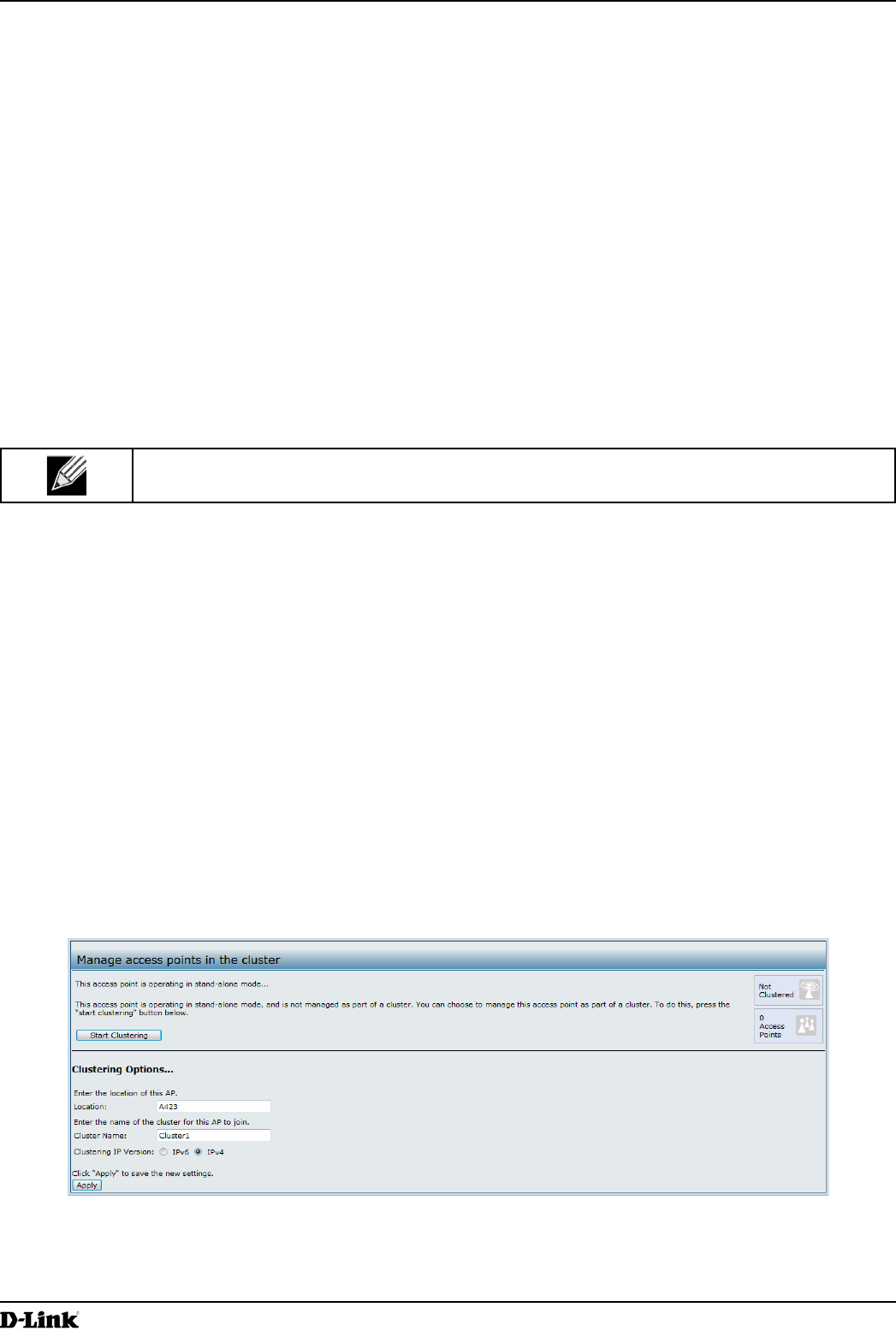
The following gure shows the Cluster > Access Points page when clustering is not enabled.
Figure 63 - Manage Access Points In The Cluster (Passive)
The following gure shows the Cluster > Access Points page when clustering is enabled and two access points are
in the cluster.
Unied Access Point Administrator’s Guide
Unied Access Point Administrator’s Guide
Page 105
March 2012
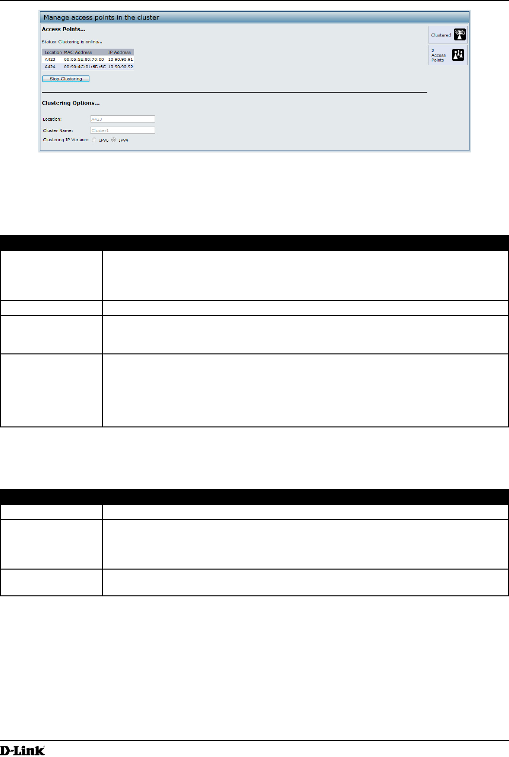
Section 9 - Clustering Multiple APs
Figure 64 - Manage Access Points In The Cluster (Active)
If clustering is currently disabled on the AP, the Start Clustering button is visible. If clustering is enabled, the Stop
Clustering button is visible. You can edit the clustering option information when clustering is disabled.
The following table describes the conguration and status information available on the cluster Access Points page.
Field Description
Status If the status eld is visible, then the AP is enabled for clustering. If clustering is not enabled,
then the AP is operating in stand-alone mode and none of the information in this table is
visible.
To disable clustering on the AP, click Stop Clustering.
Location Description of where the access point is physically located.
MAC Address Media Access Control (MAC) address of the access point.
The address shown here is the MAC address for the bridge (br0). This is the address by
which the AP is known externally to other networks.
IP Address Species the IP address for the access point.
Each IP address is a link to the Administration Web pages for that access point. You can
use the links to navigate to the Administration Web pages for a specic access point. This is
useful for viewing data on a specic access point to make sure a cluster member is picking
up cluster conguration changes, to congure advanced settings on a particular access
point, or to switch a standalone access point to cluster mode.
Table 58 - Access Points in the Cluster
The following table describes the cluster information to congure for an individual member. The clustering options are
read-only when clustering is enabled. To congure the clustering options, you must stop clustering.
Field Description
Location Enter a description of where the access point is physically located.
Cluster Name Enter the name of the cluster for the AP to join.
The cluster name is not sent to other APs in the cluster. You must congure the same cluster
name on each AP that is a member of the cluster. The cluster name must be unique for each
cluster you congure on the network.
Clustering IP
Version
Specify the IP version that the APs in the cluster use to communicate with each other.
Table 59 - Cluster Options

Unied Access Point Administrator’s Guide
Unied Access Point Administrator’s Guide
Page 106
March 2012
Section 9 - Clustering Multiple APs
Removing an Access Point from the Cluster
To remove an access point from the cluster, do the following.
1.) Go to the Administration Web pages for the clustered access point.
The Administration Web pages for the standalone access point are displayed.
2.) Click the Cluster > Access Points link in the Administration pages.
3.) Click Stop Clustering.
4.) The change will be reected under Status for that access point; the access point will now show as stand-alone
(instead of cluster).
Adding an Access Point to a Cluster
To add an access point that is currently in standalone mode back into a cluster, do the following.
1.) Go to the Administration Web pages for the standalone access point.
2.) Click the Cluster > Access Points link in the Administration pages for the stand-alone access point.
The Access Points page for a standalone access point indicates that the current mode is standalone.
3.) Type the name or location of the AP in the Location eld to identify the AP within the cluster.
4.) Type the name of the cluster for the AP to join in the Cluster Name eld.
5.) Click Start Clustering.
6.) The access point is now a cluster member. Its Status (Mode) on the Cluster > Access Points page now
indicates Cluster instead of Not Clustered.
Navigating to Conguration Information for a Specic AP
In general, the UAP is designed for central management of clustered access points. For access points in a cluster,
all access points in the cluster reect the same conguration. In this case, it does not matter which access point you
actually connect to for administration.
There may be situations, however, when you want to view or manage information on a particular access point. For
example, you might want to check status information such as client associations or events for an access point. In this
case, you can navigate to the Administration Web interface for individual access points by clicking the IP address links
on the Access Points page.
All clustered access points are shown on the Cluster > Access Points page. To navigate to clustered access points,
you can simply click on the IP address for a specic cluster member shown in the list.
Navigating to an AP by Using its IP Address in a URL
You can also link to the Administration Web pages of a specic access point, by entering the IP address for that
access point as a URL directly into a Web browser address bar in the following form:
http://IPAddressOfAccessPoint
where IPAddressOfAccessPoint is the address of the particular access point you want to monitor or congure.
Managing Cluster Sessions
The Sessions page shows information about client stations associated with access points in the cluster. Each client is
identied by its MAC address, along with the AP (location) to which it is currently connected.
To view a particular statistic for client sessions, select an item from the Display drop-down list and click Go. You can
view information about idle time, data rate, signal strength and so on; all of which are described in detail in the table
below.
Unied Access Point Administrator’s Guide
Unied Access Point Administrator’s Guide
Page 107
March 2012
Section 9 - Clustering Multiple APs
A session in this context is the period of time in which a user on a client device (station) with a unique MAC address
maintains a connection with the wireless network. The session begins when the client logs on to the network, and the
session ends when the client either logs off intentionally or loses the connection for some other reason.
Note: A session is not the same as an association, which describes a client connection to a
particular access point. A client network connection can shift from one clustered AP to another
within the context of the same session. A client station can roam between APs and maintain the
session.
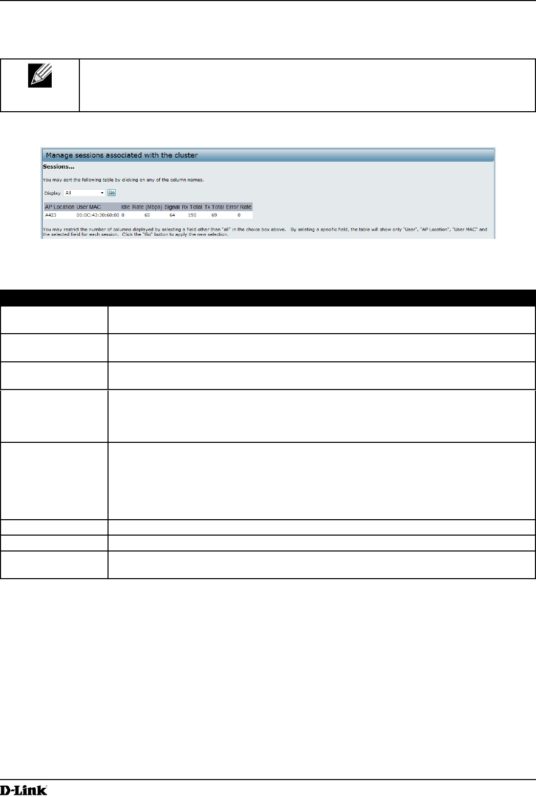
To manage sessions associated with the cluster, click Cluster > Sessions.
Figure 65 - Manage Sessions Associated With The Cluster
Details about the session information shown is described in the following table.
Field Description
AP Location Indicates the location of the access point.
This is derived from the location description specied on the Basic Settings page.
User MAC Indicates the MAC address of the wireless client device.
A MAC address is a hardware address that uniquely identies each node of a network.
Idle Indicates the amount of time this station has remained inactive.
A station is considered to be idle when it is not receiving or transmitting data.
Rate The speed at which this access point is transferring data to the specied client.
The data transmission rate is measured in megabits per second (Mbps).
This value should fall within the range of the advertised rate set for the mode in use on the
access point. For example, 6 to 54 Mbps for 802.11a.
Signal Indicates the strength of the radio frequency (RF) signal the client receives from the access
point.
The measure used for this is a value known as Received Signal Strength Indication (RSSI),
and will be a value between 0 and 100.
RSSI is determined by a mechanism implemented on the network interface card (NIC) of the
client station.
Rx Total Indicates number of total packets received by the client during the current session.
Tx Total Indicates number of total packets transmitted to the client during this session.
Error Rate Indicates the percentage of time frames are dropped during transmission on this access
point.
Table 60 - Session Management
Sorting Session Information
To sort the information shown in the tables by a particular indicator, click the column label by which you want to order
things. For example, if you want to see the table rows ordered by signal strength, click the Signal column label. The
entries will be sorted by signal strength.
Unied Access Point Administrator’s Guide
Unied Access Point Administrator’s Guide
Page 108
March 2012
Section 9 - Clustering Multiple APs
Conguring and Viewing Channel Management Settings
When Channel Management is enabled, the UAP automatically assigns radio channels used by clustered access
points. The automatic channel assignment reduces mutual interference (or interference with other access points
outside of its cluster) and maximizes Wi-Fi bandwidth to help maintain the efciency of communication over the
wireless network.
You must start channel management to get automatic channel assignments; it is disabled by default on a new AP.
At a specied interval, the Channel Manager maps APs to channel use and measures interference levels in the
cluster. If signicant channel interference is detected, the Channel Manager automatically re-assigns some or all of
the APs to new channels per an efciency algorithm (or automated channel plan). If the Channel Manager determines
that a change is necessary, that information is sent to all members of the cluster and a syslog message is generated
indicating the sender AP, new and old channel assignments.
The Channel Management page shows previous, current, and planned channel assignments for clustered access
points. By default, automatic channel assignment is disabled. You can start channel management to optimize channel
usage across the cluster on a scheduled interval.
To congure and view the channel assignments for the cluster members, click the Channel Management tab.
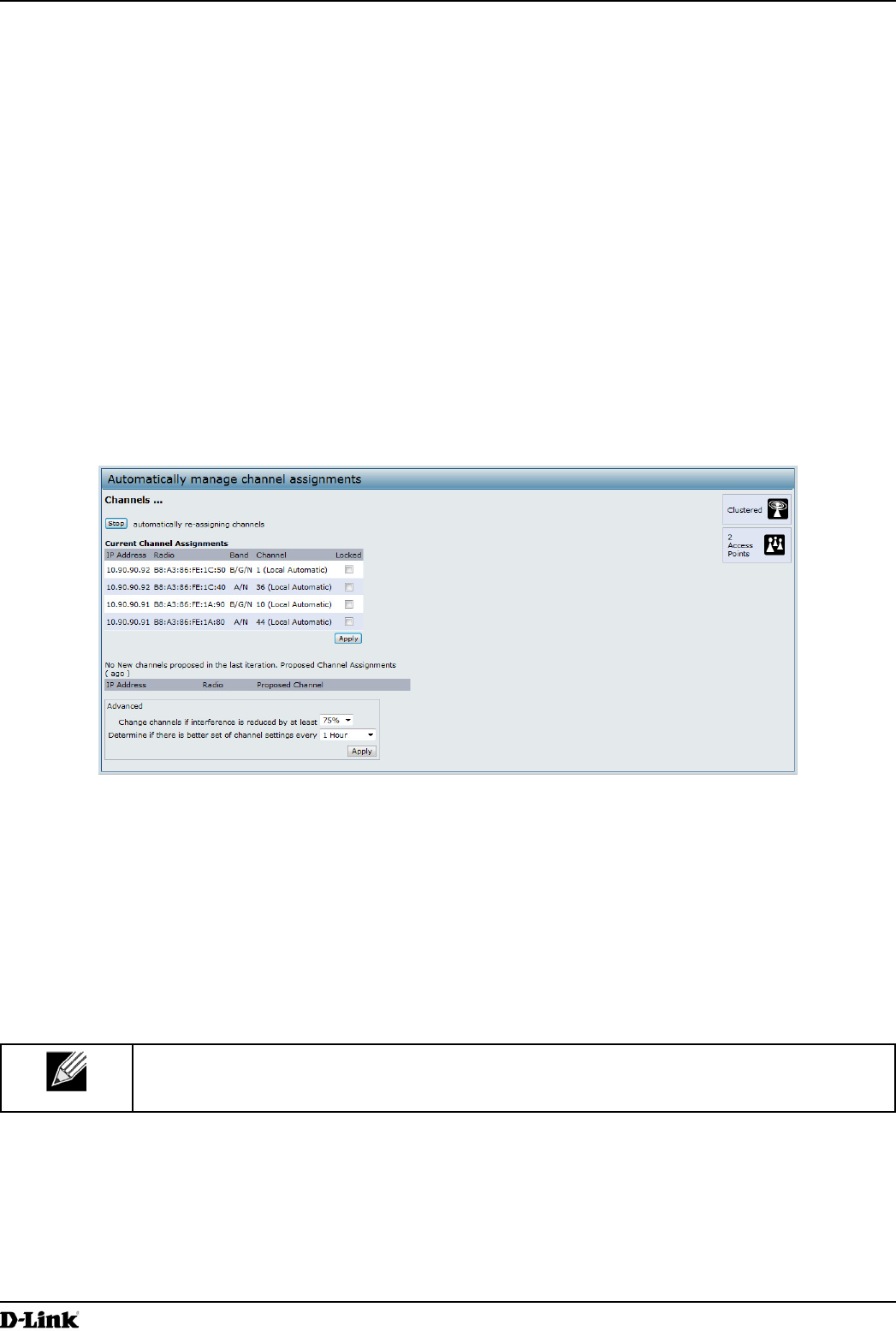
Figure 66 - Automatically Manage Channel Assignments
From this page, you can view channel assignments for all APs in the cluster and stop or start automatic channel
management. By using the Advanced settings on the page, you can modify the interference reduction potential that
triggers channel re-assignment, change the schedule for automatic updates, and re-congure the channel set used for
assignments.
Stopping/Starting Automatic Channel Assignment
By default, automatic channel assignment is disabled (off).
Note: Channel Management overrides the default cluster behavior, which is to synchronize radio
channels of all APs across a cluster. When Channel Management is enabled, the radio Channel is
not synced across the cluster to other APs.
•) Click Start to resume automatic channel assignment.
When automatic channel assignment is enabled, the Channel Manager periodically maps radio channels used
by clustered access points and, if necessary, re-assigns channels on clustered APs to reduce interference (with
cluster members or other APs outside the cluster).
•) Click Stop to stop automatic channel assignment. (No channel usage maps or channel re-assignments will be
made. Only manual updates will affect the channel assignment.)
Unied Access Point Administrator’s Guide
Unied Access Point Administrator’s Guide
Page 109
March 2012
Section 9 - Clustering Multiple APs
Viewing Current Channel Assignments and Setting Locks
The Current Channel Assignments section shows a list of all access points in the cluster by IP Address. The display
shows the band on which each AP is broadcasting (a/b/g/n), the current channel used by each AP, and an option to
lock an AP on its current radio channel so that it cannot be re-assigned to another.
The following table provides details about Current Channel Assignments.
Field Description
IP Address Species the IP Address for the access point.
Radio Identies the MAC address of the radio.
Band Indicates the band on which the access point is broadcasting.
Current Indicates the radio Channel on which this access point is currently broadcasting.
Status Shows whether the radio is up (on) or down (off).
Locked Click Locked to force the access point to remain on the current channel.
When Locked is selected (enabled) for an access point, automated channel management
plans will not re-assign the AP to a different channel as a part of the optimization strategy.
Instead, APs with locked channels will be factored in as requirements for the plan.
If you click Apply, you will see that locked APs show the same channel for the Current
Channel and Proposed Channel elds. Locked APs will keep their current channels.
Table 61 - Channel Assignments
Viewing the Last Proposed Set of Changes
The Proposed Channel Assignments shows the last channel plan. The plan lists all access points in the cluster by IP
Address, and shows the current and proposed channels for each AP. Locked channels will not be re-assigned and the
optimization of channel distribution among APs will take into account the fact that locked APs must remain on their
current channels. APs that are not locked may be assigned to different channels than they were previously using,
depending on the results of the plan.
Field Description
IP Address Species the IP Address for the access point.
Radio Indicates the radio channel on which this access point is currently broadcasting.
Proposed Channel Indicates the radio channel to which this access point would be re-assigned if the Channel
Plan is executed.
Table 62 - Last Proposed Changes
Conguring Advanced Settings
The advanced settings allow you to customize and schedule the channel plan for the cluster. If you use Channel
Management as provided (without updating Advanced Settings), channels are automatically ne-tuned once every
hour if interference can be reduced by 25 percent or more. Channels will be re-assigned even if the network is busy.
The appropriate channel sets will be used (b/g for APs using IEEE 802.11b/g and a for APs using IEEE 802.11a).
The default settings are designed to satisfy most scenarios where you would need to implement channel
management.
Use Advanced Settings to modify the interference reduction potential that triggers channel re-assignment, change
the schedule for automatic updates, and re-congure the channel set used for assignments. If there are no elds
showing in the Advanced section, click the toggle button to display the settings that modify timing and details of the
channel planning algorithm.
Unied Access Point Administrator’s Guide
Unied Access Point Administrator’s Guide
Page 110
March 2012
Section 9 - Clustering Multiple APs
Field Description
Change channels
if interference is
reduced by at least
Specify the minimum percentage of interference reduction a proposed plan must achieve in
order to be applied. The default is 75 percent.
Use the drop-down menu to choose percentages ranging from 5 percent to 75 percent.
This setting lets you set a gating factor for channel re-assignment so that the network is not
continually disrupted for minimal gains in efciency.
For example, if channel interference must be reduced by 75 percent and the proposed
channel assignments will only reduce interference by 30 percent, then channels will not be
re-assigned. However; if you re-set the minimal channel interference benet to 25 percent
and click Apply, the proposed channel plan will be implemented and channels re-assigned
as needed.
Determine if there
is better set of
channels every
Use the drop-down menu to specify the schedule for automated updates.
A range of intervals is provided, from 30 Minutes to 6 Months
The default is 1 Hour (channel usage re-assessed and the resulting channel plan applied
every hour).
Table 63 - Advanced Channel Management Settings
Click Apply under Advanced settings to apply these settings.
Advanced settings will take effect when they are applied and inuence how automatic channel management is
performed.
Viewing Wireless Neighborhood Information
The Wireless Neighborhood shows up to 20 access points per radio within range of every member of the cluster,
shows which access points are within range of which cluster members, and distinguishes between cluster members
and non-members.
Note: The Wireless Neighborhood page shows up to 20 access points per radio. To see all the
access points detected on a given cluster access point, navigate to that cluster member’s web
interface and go to the Status > Neighboring Access Points page.
For each neighbor access point, the Wireless Neighborhood view shows identifying information (SSID or Network
Name, IP Address, MAC address) along with radio statistics (signal strength, channel, beacon interval). You can click
on an AP to get additional statistics about the APs in radio range of the currently selected AP.
The Wireless Neighborhood view can help you:
•) Detect and locate unexpected (or rogue) access points in a wireless domain so that you can take action to limit
associated risks
•) Verify coverage expectations. By assessing which APs are visible at what signal strength from other APs, you
can verify that the deployment meets your planning goals.
•) Detect faults. Unexpected changes in the coverage pattern are evident at a glance in the color coded table.
Unied Access Point Administrator’s Guide
Unied Access Point Administrator’s Guide
Page 111
March 2012
Section 9 - Clustering Multiple APs
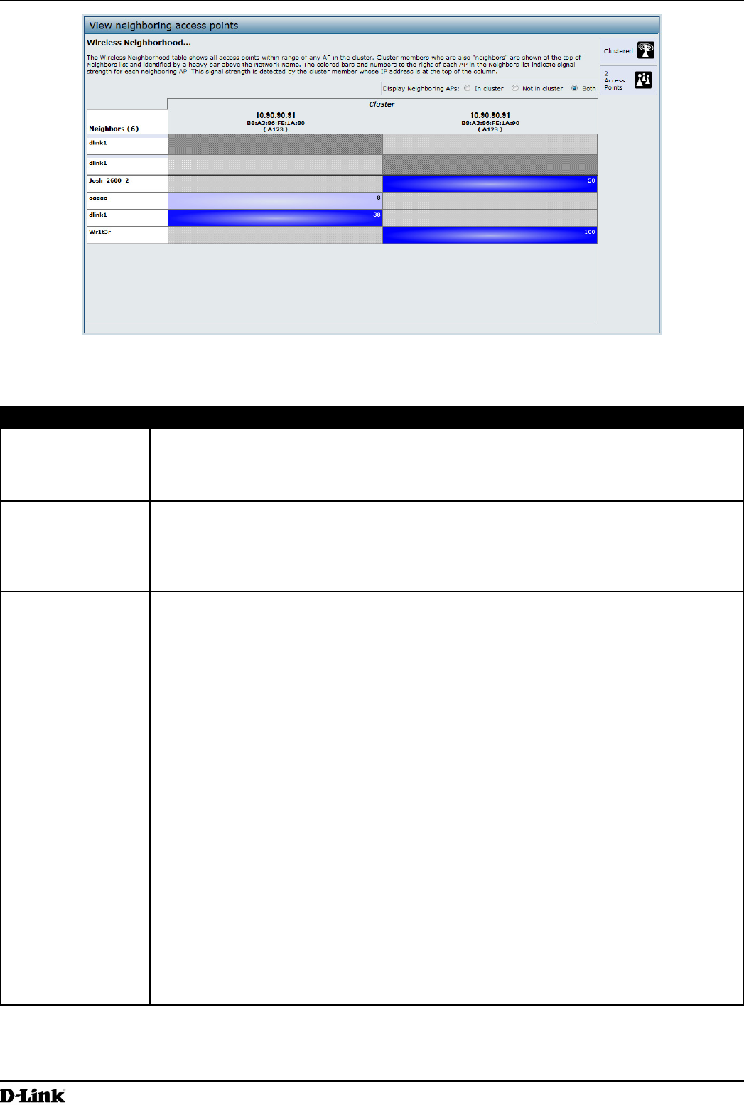
Figure 67 - View Neighboring Access Points
The following table describes details about the Wireless Neighborhood information.
Field Description
Display neighboring
APs
Click one of the following radio buttons to change the view:
•) In cluster — Shows only neighbor APs that are members of the cluster
•) Not in cluster — Shows only neighbor APs that are not cluster members
•) Both — Shows all neighbor APs (cluster members and non-members)
Cluster The Cluster list at the top of the table shows IP addresses for all access points in the cluster.
(This is the same list of cluster members shown on the Cluster > Access Points tab.)
If there is only one AP in the cluster, only a single IP address column will be displayed here;
indicating that the AP is clustered with itself.
You can click on an IP address to view more details on a particular AP.
Neighbors Access points which are neighbors of one or more of the clustered APs are listed in the left
column by SSID (Network Name).
An access point which is detected as a neighbor of a cluster member can also be a cluster
member itself. Neighbors who are also cluster members are always shown at the top of the
list with a heavy bar above and include a location indicator.
The colored bars to the right of each AP in the Neighbors list shows the signal strength for
each of the neighbor APs as detected by the cluster member whose IP address is shown at
the top of the column.
The color of the bar indicates the signal strength:
•) Dark Blue Bar — A dark blue bar and a high signal strength number (for example 50)
indicates good signal strength detected from the Neighbor seen by the AP whose IP
address is listed above that column.
•) Lighter Blue Bar — A lighter blue bar and a lower signal strength number (for example
20 or lower) indicates medium or weak signal strength from the Neighbor seen by the
AP whose IP address is listed above that column
•) White Bar — A white bar and the number 0 indicates that a neighboring AP that was
detected by one of the cluster members cannot be detected by the AP whose IP
address if listed above that column.
•) Light Gray Bar — A light gray bar and no signal strength number indicates a Neighbor
that is detected by other cluster members but not by the AP whose IP address is listed
above that column.
•) Dark Gray Bar — A dark gray bar and no signal strength number indicates this is the
AP whose IP address is listed above that column (since it is not applicable to show
how well the AP can detect itself).
Table 64 - Wireless Neighborhood Information
Unied Access Point Administrator’s Guide
Unied Access Point Administrator’s Guide
Page 112
March 2012
Section 9 - Clustering Multiple APs
Viewing Details for a Cluster Member
To view details on a cluster member AP, click on the IP address of a cluster member at the top of the page. The
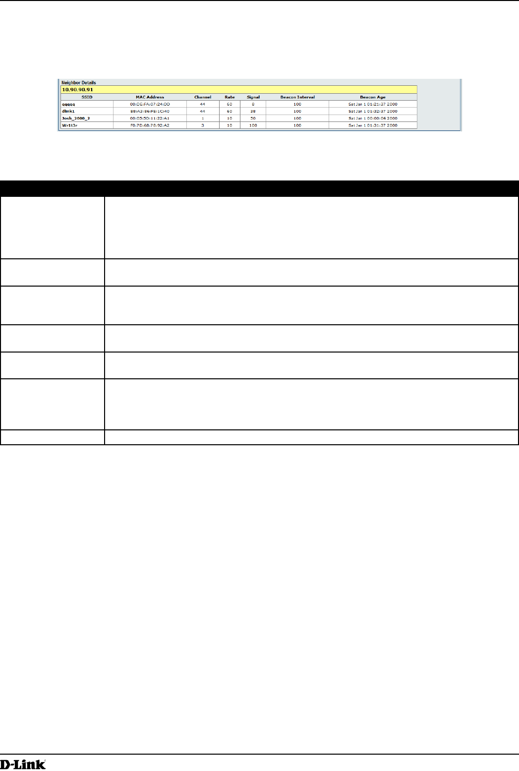
following gure shows the Neighbor Details of the AP with an IP address of 10.90.90.91.
Figure 68 - Viewing Details For A Cluster Member
The following table explains the details shown about the selected AP.
Field Description
SSID The Service Set Identier (SSID) for the access point.
The SSID is an alphanumeric string of up to 32 characters that uniquely identies a wireless
local area network. It is also referred to as the Network Name.
A Guest network and an Internal network running on the same access point must always
have two different network names.
MAC Address Shows the MAC address of the neighboring access point.
A MAC address is a hardware address that uniquely identies each node of a network.
Channel Shows the channel on which the access point is currently broadcasting.
The Channel denes the portion of the radio spectrum that the radio uses for transmitting
and receiving.
Rate Shows the rate (in megabits per second) at which this access point is currently transmitting.
The current rate will always be one of the rates shown in Supported Rates.
Signal Indicates the strength of the radio signal emitting from this access point as measured in
decibels (Db).
Beacon Interval Shows the Beacon interval being used by this access point.
Beacon frames are transmitted by an access point at regular intervals to announce the
existence of the wireless network. The default behavior is to send a beacon frame once
every 100 milliseconds (or 10 per second).
Beacon Age Shows the date and time of the last beacon received from this access point.
Table 65 - Cluster Member Details

Unied Access Point Administrator’s Guide
Unied Access Point Administrator’s Guide
Page 113
March 2012
Appendix A - Default AP Settings
Appendix A - Default AP Settings
When you rst power on a UAP, it has the default settings shown in the following table.
Feature Default
System Information
User Name admin
Password admin
Ethernet Interface Settings
Connection Type DHCP
DHCP Enabled
IP Address 10.90.90.91 (if no DHCP server is available)
Subnet Mask 255.0.0.0
DNS Name None
Management VLAN ID 1
Untagged VLAN ID 1
IPv6 Admin Mode Enabled
IPv6 Auto Cong Admin Mode Enabled
Radio Settings
Radio (1 and 2) One
Radio 1 IEEE 802.11 Mode 802.11a/n
Radio 2 IEEE 802.11 Mode 802.11b/g/n
802.11a/n Channel Auto
802.11b/g/n Channel Auto
Radio 1 Channel Bandwidth 40 MHz
Radio 2 Channel Bandwidth 20 MHz
Primary Channel Lower
Short Guard Interval Supported Yes
STBC Mode On
Protection Auto
Maximum Wireless Clients 200
Transmit Power 100 percent
Legacy Rate Sets Supported (Mbps) IEEE 802.11a: 54, 48, 36, 24, 18, 12, 9, 6
IEEE 802.11b: 11, 5.5, 2, 1
IEEE 802.11g: 54, 48, 36, 24, 18, 12, 11, 9, 6, 5.5, 2, 1
Legacy Rate Sets (Mbps)
(Basic/Advertised)
IEEE 802.11a: 24, 12, 6
IEEE 802.11b: 2, 1
IEEE 802.11g: 11, 5.5, 2, 1
MCS (Data Rate) Settings
(802.11n only)
0–15 Enabled
Broadcast/Multicast Rate Limiting Disabled
Fixed Multicast Rate Auto
Beacon Interval 100
DTIM Period 2
Fragmentation Threshold 2346
RTS Threshold 2347
TSPEC Mode Off
TSPEC Voice ACM Mode Off
Virtual Access Point Settings
Status VAP0 is enabled on both radios, all other VAPs disabled

Unied Access Point Administrator’s Guide
Unied Access Point Administrator’s Guide
Page 114
March 2012
Appendix A - Default AP Settings
Feature Default
VLAN ID 1
Network Name (SSID) dlink1 through dlink16
Broadcast SSID Allow
Security Mode None (plain text)
MAC Authentication Type None
RADIUS IP Address 10.90.90.1
RADIUS Key secret
RADIUS Accounting Disabled
Redirect Mode None
Other Default Settings
WDS Settings None
STP Disabled
MAC Authentication No stations in list
Load Balancing Disabled
SNMP Enabled
RO SNMP Community Name public
SNMP Agent Port 161
SNMP Set Requests Enabled
Managed AP Mode Enabled
Authentication (802.1X Supplicant) Disabled
Management ACL Disabled
HTTP Access Enabled; disabled in Managed Mode
HTTPS Access Enabled; disabled in Managed Mode
Console Port Access Enabled
Telnet Access Enabled; disabled in Managed Mode
SSH Access Enabled; disabled in Managed Mode
WMM Enabled
Email Alert Admin Mode Down
Time Manual (Not set)
Client QoS Global Admin Mode Disabled
Per-VAP Client QoS Mode Disabled
Clustering Stopped
Table 66 - UAP Default Settings
Unied Access Point Administrator’s Guide
Unied Access Point Administrator’s Guide
Page 115
March 2012
Appendix B - Conguration Examples
Appendix B - Conguration Examples
This appendix contains examples of how to congure selected features available on the UAP. Each example contains
procedures on how to congure the feature by using the Web interface, CLI, and SNMP.
This appendix describes how to perform the following procedures:
•) “Conguring a VAP” on page 115
•) “Conguring Radio Settings” on page 116
•) “Conguring the Wireless Distribution System” on page 118
•) “Clustering Access Points” on page 119
•) “Conguring Client QoS” on page 121
For all SNMP examples, the objects you use to AP are in a private MIB. Take DWL-6600AP for example, the path
to the tables that contain the objects is iso(1).org(3).dod(6).internet(1).private(4).enterprises(1).dlink(171).dlink-
products(10).dwl-6600AP(128).dwl6600AP(1).dwl_6600AP(1).dwlWLANAPNewMibs(26).
DWL-8600AP: 1.3.6.1.4.1.171.10.37.29.1.26
DWL-6600AP: 1.3.6.1.4.1.171.10.128.1.1.26
DWL-3600AP: 1.3.6.1.4.1.171.10.129.1.1.26
DWL-2600AP: 1.3.6.1.4.1.171.10.130.1.1.26
Conguring a VAP
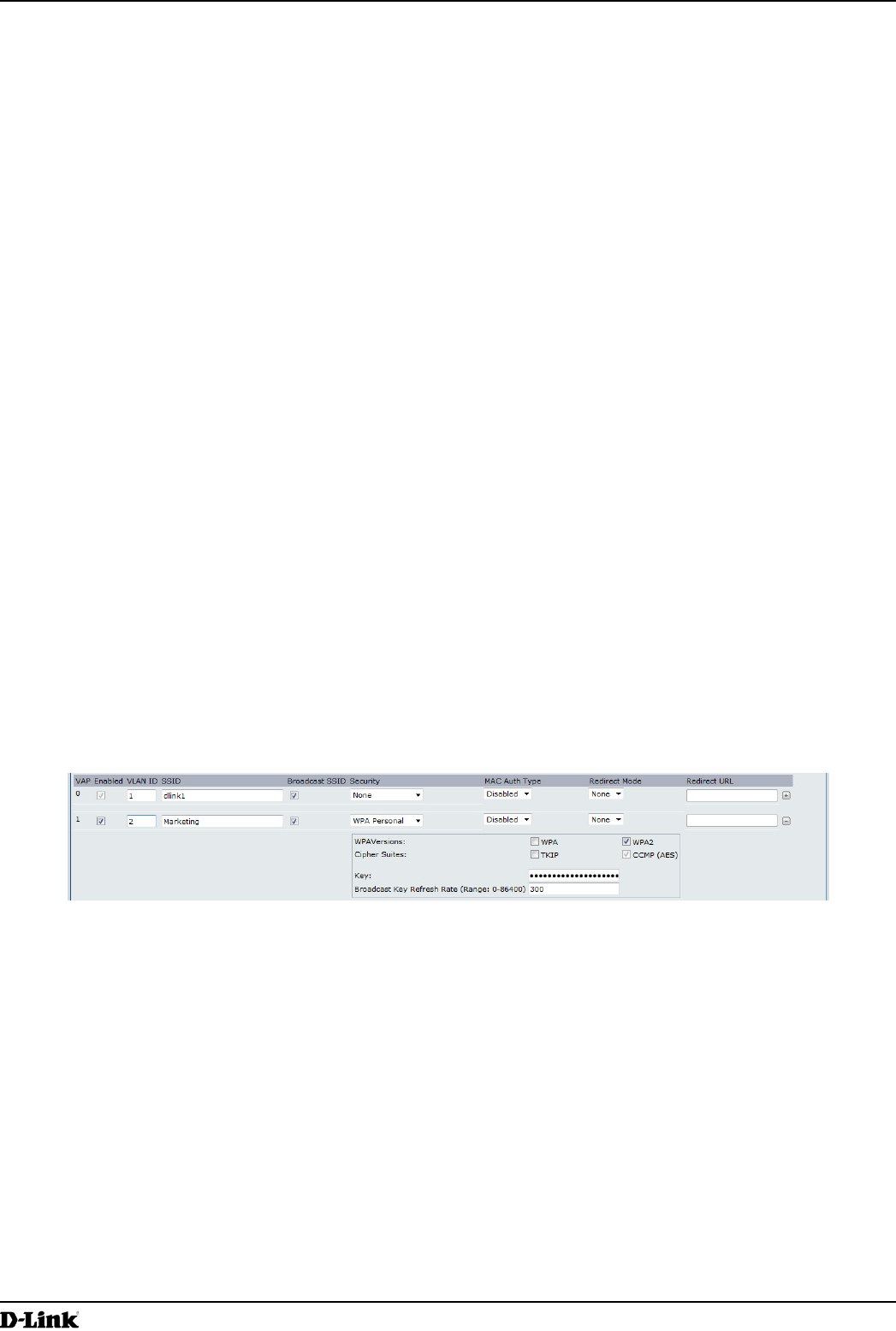
This example shows how to congure VAP 1 with the following non-default settings:
•) VLAN ID: 2
•) SSID: Marketing
•) Security: WPA Personal using WPA2 with CCMP (AES)
VAP Conguration from the Web Interface
1.) Log onto the AP and navigate to the Manage > VAP page.
Figure 69 - VAP Conguration from the Web Interface
2.) In the Enabled column for VAP 1, select the check box.
3.) Enter 2 in the VLAN ID column.
4.) In the SSID column, delete the existing SSID and type Marketing.
5.) Select WPA Personal from the menu in the Security column. Additional elds appear.
6.) Select the WPA2 and CCMP (AES) options, and clear the WPA and TKIP options.
7.) Enter a WPA encryption key in the Key eld. The key can be a mix of alphanumeric and special characters. The
key is case sensitive and can be between 8 and 63 characters.
•) Click Apply to update the AP with the new settings.
VAP Conguration from the CLI
1.) Connect to the AP by using Telnet, SSH, or a serial connection.
2.) Enable VAP 1.
set vap vap1 status up
3.) Set the VLAN ID to 2.
Unied Access Point Administrator’s Guide
Unied Access Point Administrator’s Guide
Page 116
March 2012
Appendix B - Conguration Examples
set vap vap1 vlan-id 2
Note: The previous command sets the VLAN ID to 2 for VAP 1 on both radios. To set the VLAN
ID for VAP 1 on radio one only, use the following command: set vap 1 with radio wlan0 to
vlan-id 2.
4.) Set the SSID to Marketing.
set interface wlan0vap1 ssid Marketing
5.) Set the Security Mode to WPA Personal.
set interface wlan0vap1 security wpa-personal
6.) Allow WPA2 clients, and not WPA clients, to connect to the AP.
set bss wlan0bssvap1 wpa-allowed off
set bss wlan0bssvap1 wpa2-allowed on
7.) Set the Cipher Suite to CCMP (AES) only.
set bss wlan0bssvap1 wpa-cipher-tkip off
set bss wlan0bssvap1 wpa-cipher-ccmp on
8.) Set the Pre-shared key.
set interface wlan0vap1 wpa-personal-key JuPXkC7GvY$moQiUttp2
If the shared secret keys includes spaces, place the key inside quotation marks.
9.) Use the following commands to view and verify the settings.
get interface wlan0vap1 detail
get vap vap1 detail
VAP Conguration Using SNMP
1.) Load the DLINK-WLAN-ACCESS-POINT-X600-MIB module.
2.) From the MIB tree, navigate to the objects in the apVap table.
3.) Walk the apVapDescription object to view the instance ID for VAP 1 (wlan0vap1).
VAP 1 on Radio 1 is instance 3.
4.) Use the apVapStatus object to set the status of VAP 1 to up (1).
5.) Use the apVapVlanID object to set the VLAN ID of VAP 1 to 2.
6.) Navigate to the objects in the apIfCong table.
7.) Walk the apIfCongName object to view the instance ID for VAP 1 (wlan0vap1).
VAP 1 on Radio 1 is instance 3.
8.) Set the value of instance 3 in the apIfCongSsid object to Marketing.
9.) Set the value of instance 3 in the apIfCongSecurity object to wpa-personal (3).
10.) Set the value of instance3 in the apIfCongWpaPersonalKey object to JuPXkC7GvY$moQiUttp2, which is the
WPA pre-shared key.
11.) Navigate to the objects in the apRadioBss > apBssTable table.
12.) Walk the apBssDescr object to view the instance ID for VAP 1.
VAP 1 on Radio 1 is instance 1.
13.) Set the value of instance 1 in the apBssWpaAllowed object to false (2).
14.) Set the value of instance 1 in the apBssWpaCipherTkip object to false (2).
15.) Set the value of instance 1 in the apBssWpaCipherCcmp object to true (1).
Conguring Radio Settings
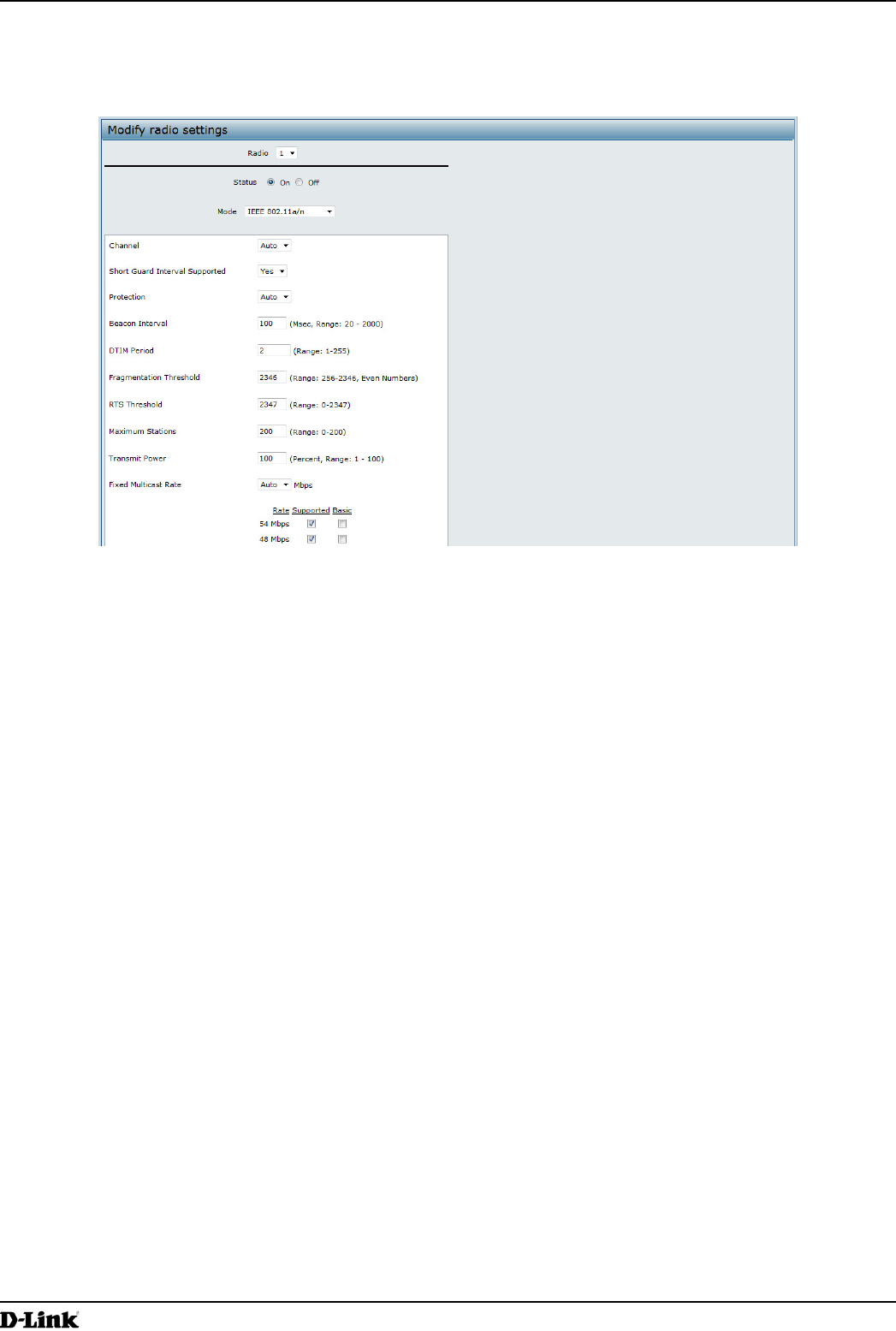
This example shows how to congure Radio 12 with the following settings:
•) Mode: IEEE 802.11b/g/n
•) Channel: 6
•) Channel Bandwidth: 40 MHz
•) Maximum Stations: 100
•) Transmit Power: 75%
Unied Access Point Administrator’s Guide
Unied Access Point Administrator’s Guide
Page 117
March 2012
Appendix B - Conguration Examples
Radio Conguration from the Web Interface
1.) Log onto the AP and navigate to the Manage > Radio page.
Figure 70 - Radio Conguration from the Web Interface
2.) Make sure that the Status is On.
3.) From the Mode menu, select IEEE 802.11b/g/n.
4.) From the Channel eld, select 6.
5.) From the Channel Bandwidth eld, select 40 MHz.
6.) In the Maximum Stations eld, change the value to 100.
7.) In the Transmit Power eld, change the value to 75.
8.) Click Apply to update the AP with the new settings.
Radio Conguration from the CLI
1.) Connect to the AP by using Telnet, SSH, or a serial connection.
2.) Turn Radio 12 on if the status is not currently up.
set radio wlan01 status on
3.) Set the mode to IEEE 802.11b/g/n.
set radio wlan01 mode bg-n
4.) Set the channel to 6.
set radio wlan01 channel-policy static
set radio wlan01 static-channel 6
5.) Set the channel bandwidth to 40 MHz.
set radio wlan01 n-bandwidth 40
6.) Allow a maximum of 100 stations to connect to the AP at a time.
set bss wlan01bssvap0 max-stations 100
7.) Set the transmit power to 75 percent.
set radio wlan01 tx-power 75
8.) View information about the radio settings.
get radio wlan01 detail
Unied Access Point Administrator’s Guide
Unied Access Point Administrator’s Guide
Page 118
March 2012
Appendix B - Conguration Examples
Radio Conguration Using SNMP
1.) Load the DLINK-WLAN-ACCESS-POINT-X600-MIB module.
2.) From the MIB tree, navigate to the objects in the apRadio table (apRadioBss > apRadioTable).
3.) Use the apRadioStatus object to set the status of Radio 12 to up (1).
4.) Use the apRadioMode object to set the Radio 12 mode to IEEE 802.11b/g/n, which is bg-n (4).
5.) Use the apRadioChannelPolicy object to set the channel policy to static (1), which disables the automatic
channel assignment.
6.) Use the apRadioStaticChannel object to set the channel to 6.
7.) Use the apRadioChannelBandwith object to set the channel bandwidth for Radio 12 to forty-MHz (2).
8.) Use the apRadioTxPower object to set the transmission power on Radio 12 to 75.
9.) Navigate to the objects in the apBssTable.
10.) Use the apBssMaxStations object to set the value of the maximum allowed stations to 100.
Conguring the Wireless Distribution System
This examples shows how to congure a WDS link between two APs. The local AP is MyAP1 and has a MAC address
of 00:1B:E9:16:32:40, and the remote AP is MyAP2 with a MAC address of 00:30:AB:00:00:B0.
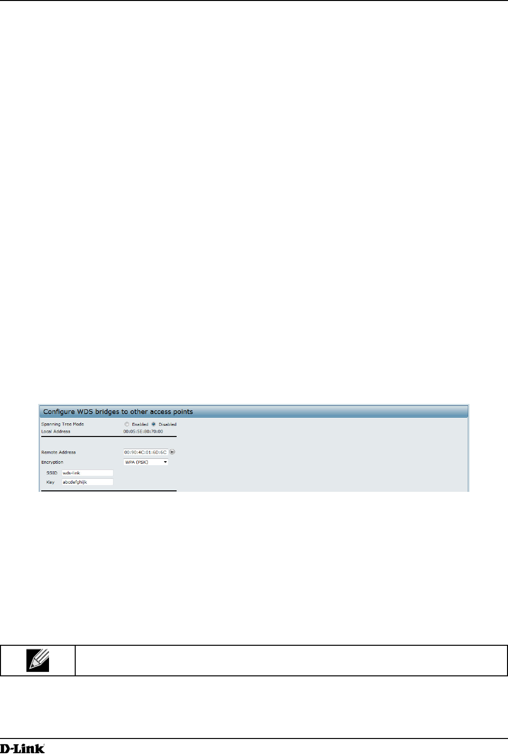
The WDS link has the following settings, which must be congured on both APs:
•) Encryption: WPA (PSK)
•) SSID: wds-link
•) Key: abcdefghijk
WDS Conguration from the Web Interface
To create a WDS link between a pair of access points “MyAP1” and “MyAP2” use the following steps:
1.) Log onto MyAP1 and navigate to the Manage > WDS page.
Figure 71 - WDS Conguration from the Web Interface
The MAC address for MyAP1 (the access point you are currently viewing) is automatically provided in the Local
Address eld.
2.) Enter the MAC address for MyAP2 in the Remote Address eld, or click the arrow next to the eld and select
the MAC address of MyAP2 from the pop-up list.
3.) Select WPA (PSK) from the Encryption menu.
4.) Enter wds-link in the SSID eld and abcdefghijk in the Key eld.
5.) Click Apply to apply the WDS settings to the AP.
6.) Log onto MyAP2 and repeat steps 2-5 (but be sure to use the MAC address of MyAP1 in the Remote Address
eld.
Note: MyAP1 and MyAP2 must be set to the same IEEE 802.11 Mode and be transmitting on the
same channel.
Unied Access Point Administrator’s Guide
Unied Access Point Administrator’s Guide
Page 119
March 2012
Appendix B - Conguration Examples
WDS Conguration from the CLI
1.) Connect to the MyAP1 by using Telnet, SSH, or a serial connection.
2.) Congure the remote MAC address for MyAP2.
set interface wlan0wds0 status up remote-mac 00:30:AB:00:00:B0
3.) Set WPA (PSK) as the encryption type for the link.
set interface wlan0wds0 wds-security-policy wpa-personal
4.) Set the SSID on the WDS link.
set interface wlan0wds0 wds-ssid wds-link
5.) Congure the encryption key.
set interface wlan0wds0 wds-wpa-psk-key abcdefghijk
6.) Administratively enable the WDS link.
set interface wlan0wds0 status up
7.) Perform the same conguration steps on MyAP2.
WDS Conguration Using SNMP
1.) Load the DLINK-WLAN-ACCESS-POINT-X600-MIB module.
2.) From the MIB tree, navigate to the objects in the apIfCong table.
3.) Walk the apIfCongName object to view the instance ID for the rst WDS link (wlan0wds0).
The rst WDS link is instance 1.
4.) Set the value of instance 1 in the apIfCongRemoteMac object to 00:30:AB:00:00:B0.
In the MG-Soft browser, the format for the MAC address value to set is # 0x00 0x30 0xAB 0x00 0x00 0xB0.
5.) Set the value of instance 1 in the apIfCongWdsSecPolicy object to WPA Personal (3).
6.) Set the value of instance 1 in the apIfCongSsid object to wds-link.
7.) Set the value of instance 1 in the apIfCongWdsWpaPskKey object to abcdefthijk.
Some MIB browsers require that the value be entered in HEX values rather than ASCII values.
8.) Perform the same conguration steps on MyAP2.
Clustering Access Points
This example shows how to congure a cluster with two APs and to enable automatic channel reassignment. The
location of the local AP is Room 214, and the cluster name is MyCluster.
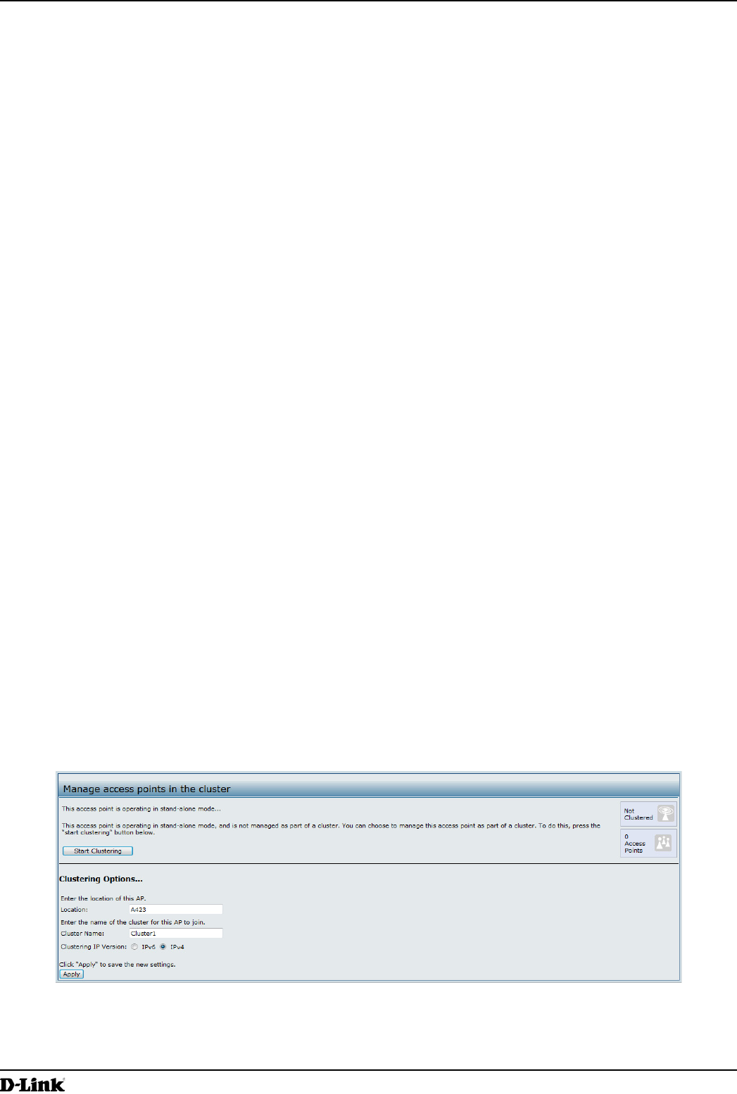
Clustering APs by Using the Web Interface
1.) Log onto the AP and navigate to the Cluster > Access Points page.
Figure 72 - Clustering APs by Using the Web Interface (Passive)
2.) If clustering has started, click Stop Clustering so you can change the Clustering Options.
3.) Enter the AP location and the name of the cluster for it to join.
4.) Click Apply.
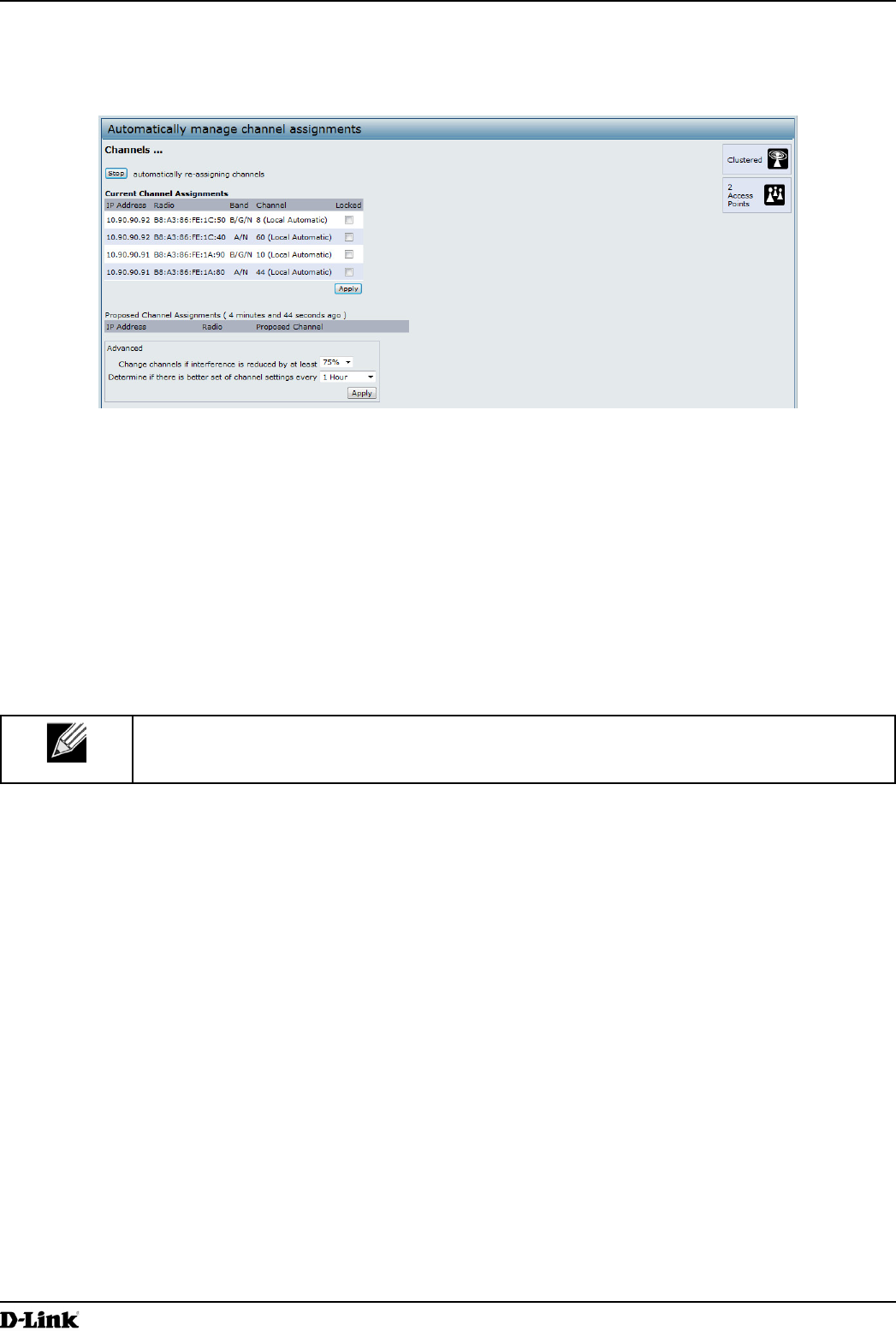
Unied Access Point Administrator’s Guide
Unied Access Point Administrator’s Guide
Page 120
March 2012
Appendix B - Conguration Examples
5.) Click Start Clustering to enable the clustering feature.
After you refresh the page, other APs that are on the same bridged segment, have radios in the same operating
mode, are enabled for clustering, and have the same cluster name appear in the Access Points table.
6.) Go to the Channel Management page to view the channel assignments.
Figure 73 - Clustering APs by Using the Web Interface (Active)
A table on the page displays the current channel assignments and the proposed channel assignments. The
interval setting in the Advanced section determine how often proposed changes are applied.
Clustering APs by Using the CLI
1.) Connect to the AP by using Telnet, SSH, or a serial connection.
2.) Stop clustering so you can change the location and cluster name.
set cluster clustered 0
3.) Set the AP Location.
set cluster cluster-name “Room 214”
Note: If the cluster name or cluster location has spaces, you must enclose the text in quotation
marks when you enter the text in the CLI, as the command example shows. You do not need to
use quotation marks when you enter text by using the Web UI.
4.) Set the cluster name.
set cluster location MyCluster
5.) Start clustering.
set cluster clustered 1
6.) View information about the cluster settings on the AP.
get cluster detail
7.) Start the automatic channel planner.
set channel-planner status up
8.) View the settings for the automatic channel planner.
get channel-planner detail
Clustering APs by Using SNMP
Cluster conguration by using SNMP is not supported.
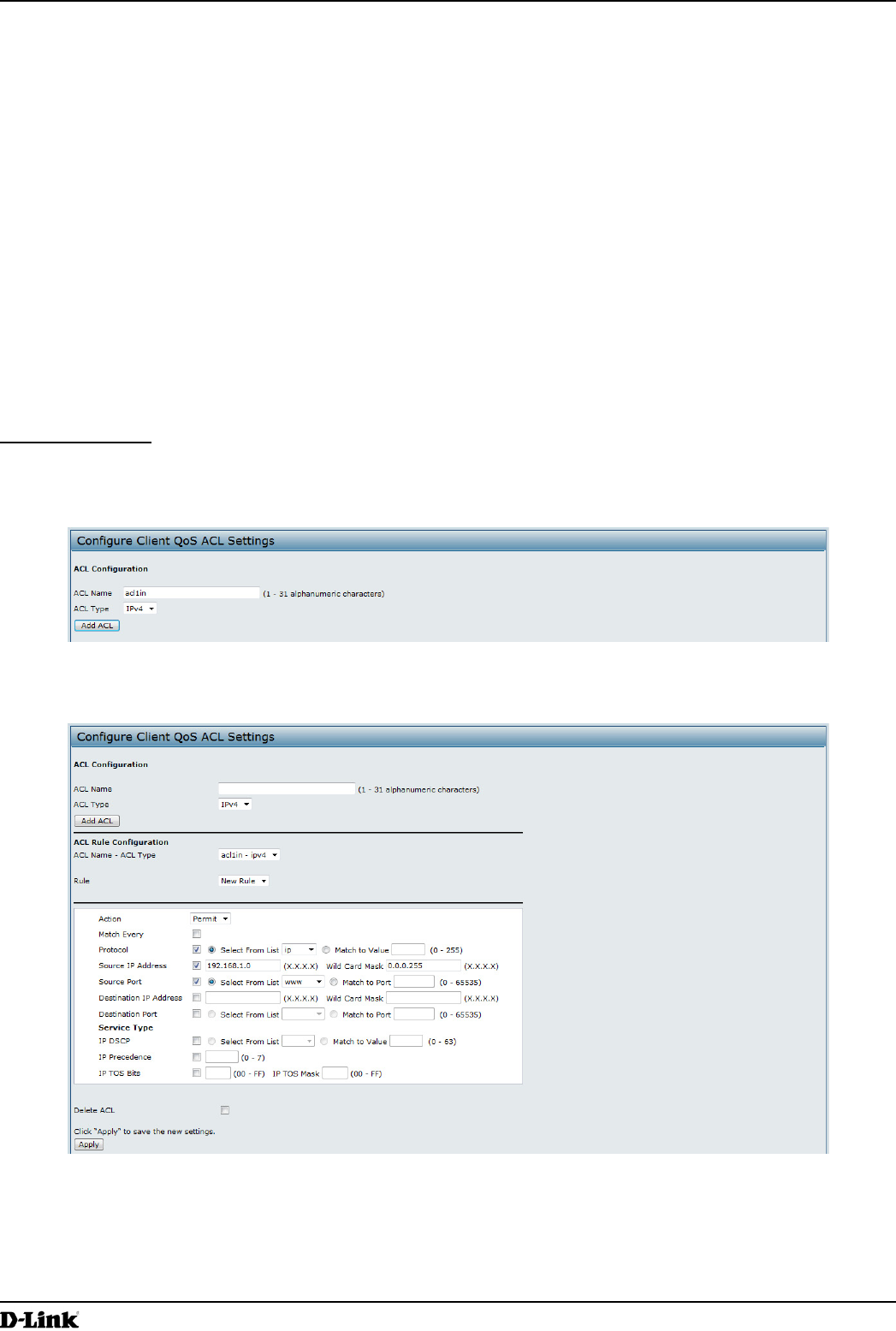
Unied Access Point Administrator’s Guide
Unied Access Point Administrator’s Guide
Page 121
March 2012
Appendix B - Conguration Examples
Conguring Client QoS
This example shows how to enable client QoS, congure an ACL and a DiffServ policy on the AP, and to apply the
ACL and the Policy to trafc transmitted from clients associated with VAP 2 and received by the AP.
The IPv4 ACL is named acl1 and contains two rules. The rst rule allows HTTP trafc from the 192.168.1.0 subnet.
The second rule allows all IP trafc from the management station (192.168.1.23). All other trafc is denied due to the
implicit deny all rule at the end of the ACL. The ACL is applied to the inbound interface on the AP so that packets are
checked when the AP receives trafc from associated clients.
The DiffServ policy in this example shows how to establish default DiffServ behavior for clients associating with the
VAP that do not obtain a DiffServ policy name through the RADIUS server. Voice trafc (UDP packets) received from
clients in the 192.168.1.0 subnet that has the VoIP server as its destination address (192.168.2.200), is marked with
the IP DSCP value for expedited forwarding so that it takes priority over other trafc.
Conguring QoS by Using the Web Interface
ACL Conguration
1.) Log onto the AP and navigate to the Client QoS > Client QoS ACL page.
2.) Enter acl1in the ACL Name eld, and click Add ACL.
Figure 74 - Conguring QoS by Using the Web Interface (ACL Name)
The screen refreshes, and additional elds appear.
Figure 75 - Conguring QoS by Using the Web Interface (Rule1)
3.) From the Action menu, select Permit.
4.) Clear the Match Every option.
5.) Verify that the Protocol option is selected and IP is selected from the Select From List menu.
6.) Congure the remaining settings:
•) Source IP Address: 192.168.1.0
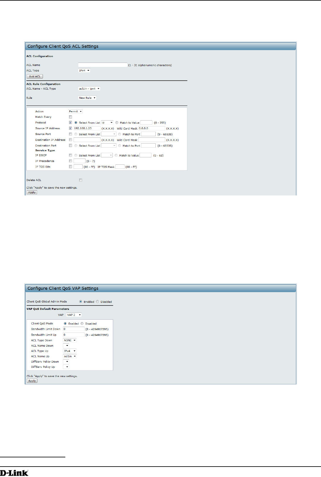
Unied Access Point Administrator’s Guide
Unied Access Point Administrator’s Guide
Page 122
March 2012
Appendix B - Conguration Examples
•) Wild Card Mask: 0.0.0.255
•) Source Port: Select the option
•) Select From List (Source Port): www
7.) Click Apply to save the rule.
Figure 76 - Conguring QoS by Using the Web Interface (Rule2)
8.) Select New Rule from the Rule menu and create another rule with the following settings:
•) Action: Permit
•) Match Every: Clear the option
•) Protocol: IP
•) Address: 192.168.1.23
•) Wild Card Mask: 0.0.0.0
9.) Click Apply to save the rule.
10.) Navigate to the Client QoS > VAP QoS Parameters page.
Figure 77 - Conguring QoS by Using the Web Interface (VAP QoS Parameters)
11.) For the Client QoS Global Admin Mode option, select Enabled.
12.) From the VAP menu, select VAP 2.
13.) Select the Enabled option for Client QoS Mode.
14.) From the ACL Type Up menu, select IPv4.
15.) From the ACL Name Up menu, select acl1in.
16.) Click Apply to update the AP with the QoS settings.
DiffServ Conguration
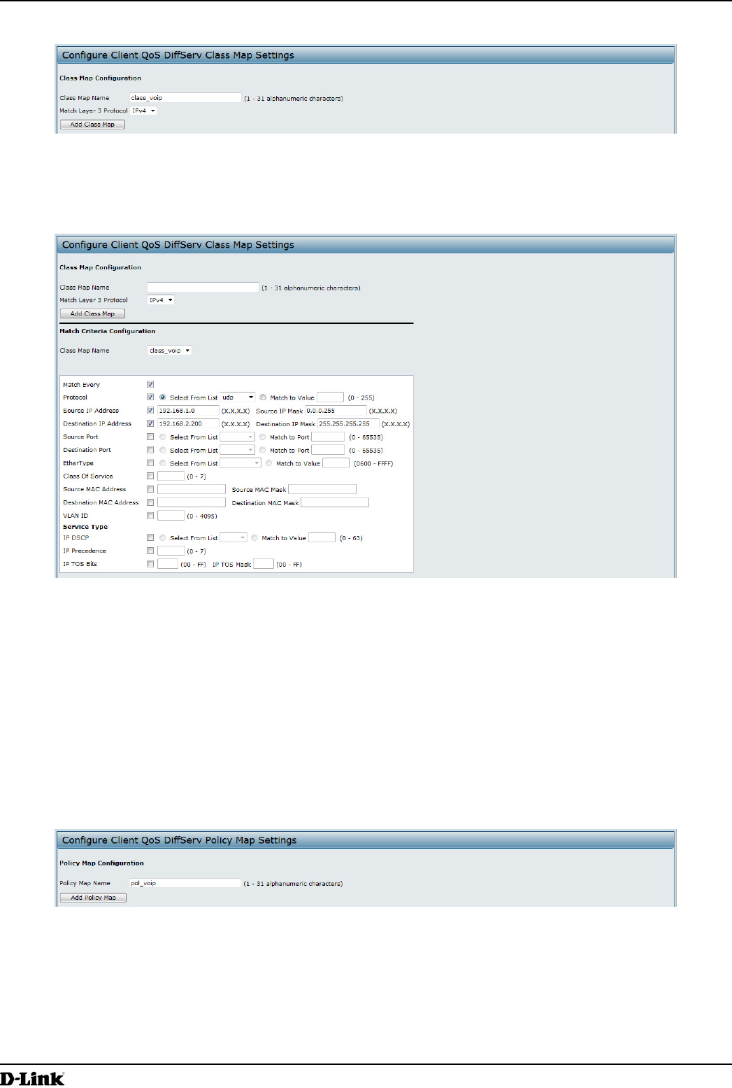
Unied Access Point Administrator’s Guide
Unied Access Point Administrator’s Guide
Page 123
March 2012
Appendix B - Conguration Examples
1.) Log onto the AP and navigate to the Client QoS > Class Map page.
Figure 78 - Conguring QoS by Using the Web Interface (Class Map Name)
2.) Enter class_voip in the Class Map Name eld and click Add Class Map.
The page refreshes and additional elds appear.
Figure 79 - Conguring QoS by Using the Web Interface (Rule)
3.) Select the Match Every option to indicate that all match criteria dened for the class must be satised in order
for a packet to be considered a match.
4.) Select Protocol, and then select UDP from the Select From List eld to dene UDP as a match criteria.
5.) Select Source IP Address and enter the following information:
•) Address: 192.168.1.0
•) Source IP Mask: 255.255.255.0
6.) Select the Destination IP Address option and enter the following information for the VoIP server:
•) Address: 192.168.2.200
•) Destination IP Mask: 255.255.255.255
7.) Click Apply to save the match criteria.
8.) Navigate to the Client QoS > Policy Map page.
Figure 80 - Congure Client QoS DiffServ Policy Map Settings (Policy Map Name)
9.) To create a policy, enter pol_voip into the Policy Map Name eld, and then click Add Policy Map.
The page refreshes and additional elds appear.
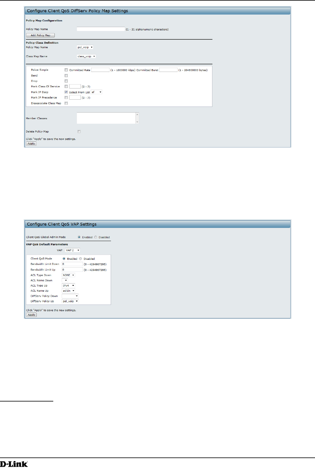
Unied Access Point Administrator’s Guide
Unied Access Point Administrator’s Guide
Page 124
March 2012
Appendix B - Conguration Examples
Figure 81 - Congure Client QoS DiffServ Policy Map Settings (Rule)
10.) For the class_voip Class Map, select the Mark IP Dscp option, and then select ef from the Select From List
menu.
11.) Trafc that meets the criteria dened in the class_voip class is marked with a DSCP value of EF (expedited
forwarding).
12.) Click Apply to save the policy.
13.) Navigate to the Client QoS > VAP QoS Parameters page.
Figure 82 - Congure Client QoS VAP Settings
14.) Select VAP 2 from the VAP menu.
15.) Make sure that the Client QoS Global Admin Mode and the QoS Mode are both enabled.
16.) From the DiffServ Policy Up menu, select pol_voip.
17.) Click Apply to update the AP with the QoS settings.
Conguring QoS by Using the CLI
ACL Conguration
1.) Connect to the AP.
2.) Create an ACL named acl1.
add acl acl1 acl-type ipv4
3.) Add a rule to acl1 that allows HTTP trafc from the 192.168.1.0 subnet.
add rule acl-name acl2 acl-type ipv4 action permit protocol ip src-ip 192.168.1.0 src-ip-
mask 0.0.0.255 src-port http

Unied Access Point Administrator’s Guide
Unied Access Point Administrator’s Guide
Page 125
March 2012
Appendix B - Conguration Examples
4.) Add another rule to acl1 that allows all trafc from the host with an IP address of 192.168.1.23.
add rule acl-name acl2 acl-type ipv4 action permit protocol ip src-ip 192.168.1.23 src-ip-
mask 0.0.0.0
5.) Enable Client QoS on the AP.
set client-qos mode up
6.) Enable Client QoS on VAP2
set vap wlan0vap2 qos-mode up
7.) Apply acl1 to VAP2 in the inbound direction (from the client to the AP).
set vap wlan0vap2 def-acl-up acl1
DiffServ Conguration
1.) Log onto the AP CLI.
2.) Create a class map named class_voip and congure it to match all UDP packets from the 192.168.1.0 network
that have a destination IP address of 192.168.2.200 (the VoIP server).
add class-map class_voip every yes protocol udp src-ip 192.168.1.0 src-ip-mask 255.255.255.0
dst-ip 192.168.2.200 dst-ip-mask 255.255.255.255
3.) Add a policy map named pol_voip.
add policy-map pol_voip
4.) Dene the pol_voip policy map by adding the class_voip class map and specifying that packets that match the
class_voip criteria will be marked with a DSCP value of EF (expedited forwarding).
add policy-attr policy-map-name pol_voip class-map-name class_voip mark-ip-dscp ef
5.) Enable Client QoS on the AP.
set client-qos mode up
6.) Enable Client QoS on VAP2
set vap wlan0vap2 qos-mode up
7.) Apply pol_voip to VAP2 in the inbound direction (from the client to the AP).
set vap wlan0vap2 def-policy-up pol_voip
Conguring QoS by Using SNMP
ACL Conguration
1.) Load the DLINK-WLAN-ACCESS-POINT-X600-MIB module.
2.) From the MIB tree, navigate to the objects in the apQos > apAclTable.
3.) Use the apQosAclStatus object to create a row entry with apQosAclName and apQosAclType as the indexes
for apQosAclEntry.
The new apQosAclEntry value includes the apQosAclType (1) followed by the number of characters in the name
(4), and then the ASCII code for the name. In this example, acl1 is 97.99.108.49. The value to set is 4, which is
Create and Go.
4.) Add a rule to acl1 that allows HTTP trafc from the 192.168.1.0 subnet.
•) Use 1.3.6.1.4.1.171.10.128.1.1.26.10.3.1.14.1.4.97.99.108.49.1 to set the apQosAclRuleStatus of Rule 1 to
active (1)
In the OID, the 14 (bold) is the sequence identier for the apQosAclRuleStatuss object, 1 is the ACL type,
4.97.99.108.49 is the ACL name (the number of characters followed by the ASCII code), and the nal 1 is the
ACL rule number.
•) Use 1.3.6.1.4.1.171.10.128.1.1.26.10.3.1.4.1.4.97.99.108.49.1 to set the apQosAclRuleSrcIpAddress to a
value of 192.168.1.0.
•) Use 1.3.6.1.4.1.171.10.128.1.1.26.10.3.1.5.1.4.97.99.108.49.1 to set the apQosAclRuleSrcIpMask to a value
of 0.0.0.255.
•) Use 1.3.6.1.4.1.171.10.128.1.1.26.10.3.1.3.1.4.97.99.108.49.1 to set apQosAclRuleProtocol to a value of 80
(HTTP).
•) Use 1.3.6.1.4.1.171.10.128.1.1.26.10.3.1.16.1.4.97.99.108.49.1 to set apQosAclRuleCommit to a value of 1
(true), which saves the rule.
5.) Add another rule to acl1 that allows all trafc from the host with an IP address of 192.168.1.23.
•) Use 1.3.6.1.4.1.171.10.128.1.1.26.10.3.1.14.1.4.97.99.108.49.2 to set the apQosAclRuleStatus of Rule 2 to
active (1)
•) Use 1.3.6.1.4.1.171.10.128.1.1.26.10.3.1.4.1.4.97.99.108.49.2 to set the apQosAclRuleSrcIpAddress to a
value of 192.168.1.23.
•) Use 1.3.6.1.4.1.171.10.128.1.1.26.10.3.1.5.1.4.97.99.108.49.2 to set the apQosAclRuleSrcIpMask to a value
of 0.0.0.0.

Unied Access Point Administrator’s Guide
Unied Access Point Administrator’s Guide
Page 126
March 2012
Appendix B - Conguration Examples
•) Use 1.3.6.1.4.1.171.10.128.1.1.26.10.3.1.16.1.4.97.99.108.49.2 to set apQosAclRuleCommit to a value of 1
(true), which saves the rule.
6.) Use the apQosGlobalMode object to set the status to up (1), which enables Client QoS on the AP.
7.) Walk the apVapDescription object to view the instance ID for VAP 2 (wlan0vap2).
VAP 2 on Radio 1 is instance 5.
8.) Use the apVapQosMode object to set the status of VAP 2 to up (1).
9.) Use the apVapAclUp object to apply acl1 to VAP2 in the inbound direction (from the client to the AP).
The ACL name is the text string, and not the ASCII code.
DiffServ Conguration
1.) Load the DLINK-WLAN-ACCESS-POINT-X600-MIB module.
2.) From the MIB tree, navigate to the objects in the apQos > apAclTable.
3.) Use the apQosDsClassMapStatus object to set the status of the class map named class_voip to Create and
Go (4).
The OID to set is 1.3.6.1.4.1.171.10.128.1.1.26.10.4.1.3.10.99.108.97.115.115.95.118.111.105.112, where 10 is
the number of characters, and 99.108.97.115.115.95.118.111.105.112 is class_voip in ASCII code.
4.) Congure class_voip to match all UDP packets from the 192.168.1.0 network that have a destination IP address
of 192.168.2.200 (the VoIP server).
•) Set apQosDsClassMapMatchEvery to true (1).
•) Set apQosDsClassMapMatchProtocol to UDP (17).
•) Set apQosDsClassMapMatchSrcIpAddress to 192.168.1.0.
•) Set apQosDsClassMapMatchSrcIpMask to 255.255.255.0.
•) Set apQosDsClassMapMatchDestIpAddress to 192.168.2.200.
•) Set apQosDsClassMapMatchDestIpMask to 255.255.255.255
•) Set apQosDsClassMapMatchCommit to true (1).
5.) Create a policy map named pol_voip (which is 112.111.108.95.118.111.105.112 in ASCII) by setting the value of
the OID 1.3.6.1.4.1.171.10.128.1.1.26.10.5.1.2.8.112.111.108.95.118.111.105.112 to Create and Go (4).
6.) Dene the pol_voip policy map by adding the class_voip class map and specifying that packets that match the
class_voip criteria will be marked with a DSCP value of EF (expedited forwarding).
•) Set
apQosDsPolicyMapAttrStatus.8.112.111.108.95.118.111.105.112.10.99.108.97.115.115.95.118.111.105.112.1
to a value of 4 (Create and Go)
•) Set
apQosDsPolicyMapAttrMarkIpDscp.8.112.111.108.95.118.111.105.112.10.99.108.97.115.115.95.118.111.105.
112.1 to 46 (which is the equivalent of ef).
7.) Enable Client QoS on the AP.
set client-qos mode up
8.) Use the apQosGlobalMode object to set the status to up (1), which enables Client QoS on the AP.
9.) Walk the apVapDescription object to view the instance ID for VAP 2 (wlan0vap2).
VAP 2 on Radio 1 is instance 5.
10.) Use the apVapQosMode object to set the status of VAP 2 to up (1).
11.) Use the apVapPolUp object to apply pol_voip to VAP2 in the inbound direction (from the client to the AP).
The policy name is the text string, and not the ASCII code.
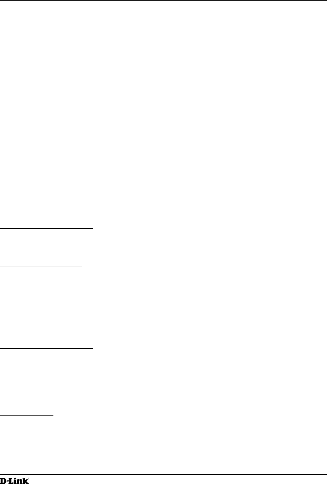
Unied Access Point Administrator’s Guide
Unied Access Point Administrator’s Guide
Page 127
March 2012
Appendix C - Statements
Appendix C - Statements
Federal Communication Commission Interference Statement
This device complies with Part 15 of the FCC Rules. Operation is subject to the following two conditions: (1) This device
may not cause harmful interference, and (2) this device must accept any interference received, including interference
that may cause undesired operation.
This equipment has been tested and found to comply with the limits for a Class B digital device, pursuant to Part 15 of
the FCC Rules. These limits are designed to provide reasonable protection against harmful interference in a residential
installation. This equipment generates, uses and can radiate radio frequency energy and, if not installed and used
in accordance with the instructions, may cause harmful interference to radio communications. However, there is no
guarantee that interference will not occur in a particular installation. If this equipment does cause harmful interference
to radio or television reception, which can be determined by turning the equipment off and on, the user is encouraged to
try to correct the interference by one of the following measures:
•) Reorient or relocate the receiving antenna.
•) Increase the separation between the equipment and receiver.
•) Connect the equipment into an outlet on a circuit different from that to which the receiver is connected.
•) Consult the dealer or an experienced radio/TV technician for help.
FCC Caution: Any changes or modications not expressly approved by the party responsible for compliance could void
the user’s authority to operate this equipment.
This transmitter must not be collocated or operating in conjunction with any other antenna or transmitter.
Note: The country code selection is for non-US model only and is not available to all US model. Per FCC regulation, all
WiFi product marketed in US must xed to US operation channels only.
Radiation Exposure Statement:
This equipment complies with FCC radiation exposure limits set forth for an uncontrolled environment. This equipment
should be installed and operated with minimum distance 20cm between the radiator & your body.
Industry Canada statement:
This device complies with RSS-210 of the Industry Canada Rules. Operation is subject to the following two conditions:
(1) This device may not cause harmful interference, and (2) this device must accept any interference received, including
interference that may cause undesired operation.
Ce dispositif est conforme à la norme CNR-210 d’Industrie Canada applicable aux appareils radio exempts de licence.
Son fonctionnement est sujet aux deux conditions suivantes: (1) le dispositif ne doit pas produire de brouillage
préjudiciable, et (2) ce dispositif doit accepter tout brouillage reçu, y compris un brouillage susceptible de provoquer un
fonctionnement indésirable.
Radiation Exposure Statement:
This equipment complies with IC radiation exposure limits set forth for an uncontrolled environment. This equipment
should be installed and operated with minimum distance 20cm between the radiator & your body.
Declaration d’exposition aux radiations:Cet equipement est conforme aux limites d’exposition aux rayonnements IC
etablies pour un environnement non controle. Cet equipement doit etre installe et utilise avec un minimum de 20 cm de
distance entre la source de rayonnement et votre corps.
CE Mark Warning:
This is a Class B product. In a domestic environment, this product may cause radio interference, in which case the user
may be required to take adequate measures.

Unied Access Point Administrator’s Guide
Unied Access Point Administrator’s Guide
Page 128
March 2012
Appendix C - Statements
NCC Statement:
經型式認證合格之低功率射頻電機,非經許可,公司、商號或使用者均不得擅自變更頻率、加大功率或變更原設計之特
性及功能。
低功率射頻電機之使用不得影響飛航安全及干擾合法通信;經發現有干擾現象時,應改善至無干擾時方得繼續使用。前
項合法通信,指依電信法規定作業之無線電通信。低功率射頻電機須忍受合法通信或工業、科學及醫療用電波輻射性電
機設備之干擾。