D Link WL2600APA1 802.11n Single-band Unified Access Point User Manual Part 3
D Link Corporation 802.11n Single-band Unified Access Point Part 3
D Link >
Contents
- 1. User Manual Part 1
- 2. User Manual Part 2
- 3. User Manual Part 3
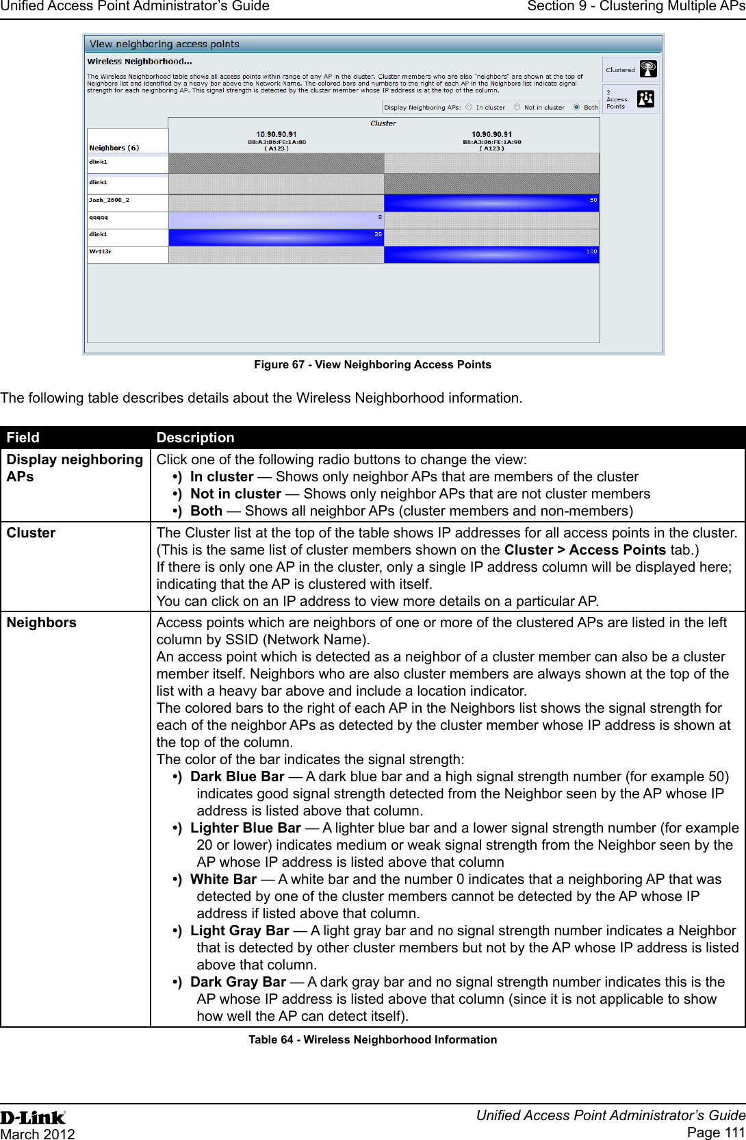
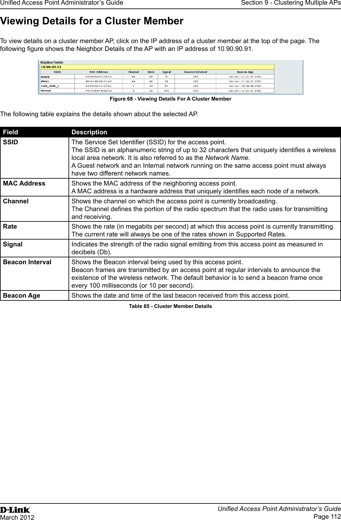
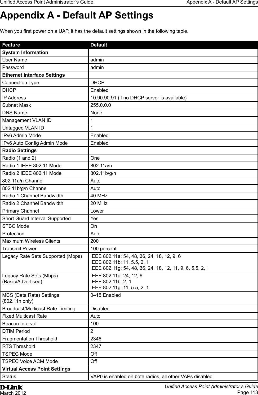
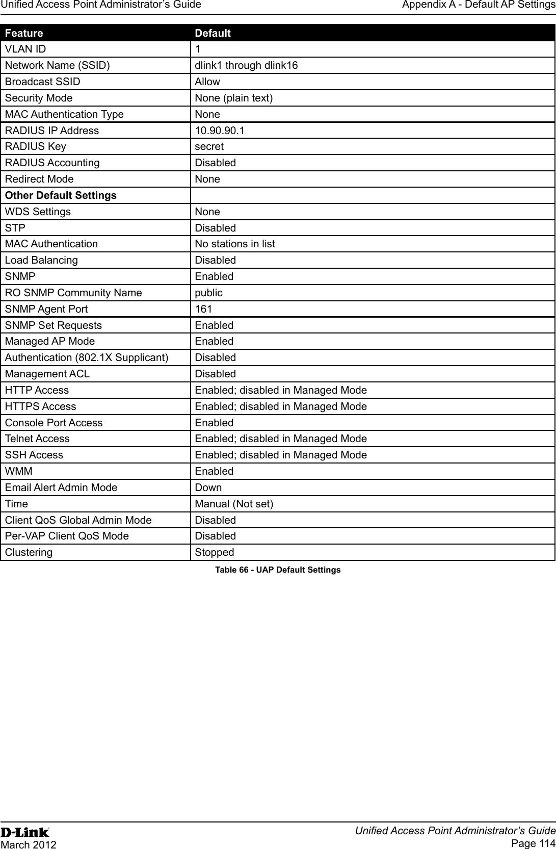
User Manual Part 3