D Link WL2600APA1 802.11n Single-band Unified Access Point User Manual Part 1
D Link Corporation 802.11n Single-band Unified Access Point Part 1
D Link >
Contents
- 1. User Manual Part 1
- 2. User Manual Part 2
- 3. User Manual Part 3
User Manual Part 1

Page 1
March 2012

Page 2
March 2012
Table of Contents
Section 1 - About This Document ............................................................................................9
Document Organization ......................................................................................................................................... 9
Additional Documentation ..................................................................................................................................... 9
Document Conventions ......................................................................................................................................... 9
Online Help, Supported Browsers, and Limitations ............................................................................................. 10
Section 2 - Getting Started ...................................................................................................... 11
Administrator’s Computer Requirements ............................................................................................................ 11
Wireless Client Requirements ............................................................................................................................. 12
Dynamic and Static IP Addressing on the AP ...................................................................................................... 13
Recovering an IP Address ............................................................................................................................. 13
Discovering a Dynamically Assigned IP Address .......................................................................................... 13
Installing the UAP ................................................................................................................................................ 13
Basic Settings ...................................................................................................................................................... 16
Connecting to the AP Web Interface by Using the IPv6 Address .................................................................. 17
Using the CLI to View the IP Address.................................................................................................................. 17
....................................................................................................................... 18
............................................................................................... 18
............................................................................................................. 19
..................................................................... 20
Verifying the Installation ...................................................................................................................................... 20
............................................................................................. 21
Section 3 - Viewing Access Point Status ............................................................................... 22
Viewing Interface Status ...................................................................................................................................... 22
Wired Settings (Internal Interface) ................................................................................................................ 22
Wireless Settings .......................................................................................................................................... 22
.................................................................................................................................................... 23
........................................................................................................ 23
.................................................................................. 24
.................................................................... 24
Viewing Transmit and Receive Statistics ............................................................................................................. 25
Viewing Associated Wireless Client Information ................................................................................................. 26
.................................................................................................................... 26
Link Integrity Monitoring ................................................................................................................................ 28
Viewing Rogue AP Detection............................................................................................................................... 28
...................................................................................................... 30
Viewing Managed AP DHCP Information ............................................................................................................ 31
.............................................................................................. 31
........................................................................................................... 32
Viewing Radio Statistics Information ................................................................................................................... 33
............................................................................................................... 34
Section 4 - Managing the Access Point .................................................................................35
................................................................................................................................................. 35
Wireless Settings ................................................................................................................................................. 37
Using the 802.11h Wireless Mode ................................................................................................................. 39
......................................................................................................... 39
Modifying Radio Settings ..................................................................................................................................... 40
................................................................................................................ 44
Scheduler Association Settings ........................................................................................................................... 46
Virtual Access Point Settings ............................................................................................................................... 47
None (Plain-text) ........................................................................................................................................... 50
.................................................................................................................................................... 50
.................................................................................................................................................. 51
WPA Personal ............................................................................................................................................... 53
............................................................................................................................................. 54
......................................................................................... 56
...................................................................................................................................... 58
.............................................................................................................................. 58

Page 3
March 2012
Controlling Access by MAC Authentication ......................................................................................................... 59
..................................................................................... 59
.............................................................................. 60
................................................................................................................................ 60
Managed Access Point Overview ........................................................................................................................ 61
Transitioning Between Modes ....................................................................................................................... 61
................................................................................................ 62
...................................................................................................................... 63
Creating a Management Access Control List (ACL) ............................................................................................ 64
....................................................................65
Web Server Settings ........................................................................................................................................... 65
.............................................................................................................. 66
Setting the SSH Status ........................................................................................................................................ 68
Setting the Telnet Status ..................................................................................................................................... 69
............................................................................................................................. 69
........................................................................................................................................ 72
....................................................................................................................... 73
............................................................................................75
................................................................................................................................ 75
.............................................................................................................................. 76
................................................................................................................................ 77
.............................................................................................................................. 78
Section 7 - Maintaining the Access Point ..............................................................................79
............................................................................................. 79
.................................................................................. 80
Performing AP Maintenance ................................................................................................................................ 81
................................................................................................. 81
Rebooting the Access Point .......................................................................................................................... 81
...................................................................................................................................... 81
........................................................................................................ 83
Packet Capture Status .................................................................................................................................. 83
..................................................................................................... 84
....................................................................................................................................... 84
Remote Packet Capture ................................................................................................................................ 85
...................................................................................................................... 87
......................................................88
...................................................................................................................... 88
................................................................................................................................. 89
IPv4 and IPv6 ACLs ...................................................................................................................................... 89
MAC ACLs ..................................................................................................................................................... 90
........................................................................................................................... 90
Creating a DiffServ Class Map ............................................................................................................................ 95
........................................................................................................................................... 96
Creating a DiffServ Policy Map ......................................................................................................................... 100
.............................................................................................................................................. 101
................................................................................... 102
Section 9 - Clustering Multiple APs .....................................................................................104
Managing Cluster Access Points in the Cluster ................................................................................................. 104
Clustering APs ............................................................................................................................................. 104
................................................................................................. 104
Removing an Access Point from the Cluster ............................................................................................... 106
Adding an Access Point to a Cluster ........................................................................................................... 106
........................................................................... 106
Navigating to an AP by Using its IP Address in a URL ................................................................................ 106
Managing Cluster Sessions ............................................................................................................................... 106
Sorting Session Information ........................................................................................................................ 107
................................................................................. 108
Stopping/Starting Automatic Channel Assignment ...................................................................................... 108
Viewing Current Channel Assignments and Setting Locks ......................................................................... 109

Page 4
March 2012
Viewing the Last Proposed Set of Changes ................................................................................................ 109
................................................................................................................... 109
Viewing Wireless Neighborhood Information .................................................................................................... 110
Viewing Details for a Cluster Member ......................................................................................................... 112
Appendix A - Default AP Settings ......................................................................................... 113
................................................................................115
............................................................................................................................................. 115
................................................................................................. 115
.................................................................................................................. 115
................................................................................................................. 116
................................................................................................................................ 116
............................................................................................... 117
................................................................................................................ 117
............................................................................................................... 118
................................................................................................... 118
................................................................................................ 118
................................................................................................................. 119
................................................................................................................ 119
Clustering Access Points ................................................................................................................................... 119
Clustering APs by Using the Web Interface ................................................................................................ 119
Clustering APs by Using the CLI ................................................................................................................. 120
Clustering APs by Using SNMP .................................................................................................................. 120
..................................................................................................................................... 121
............................................................................................. 121
.............................................................................................................. 124
Appendix C - Statements ......................................................................................................127

Page 5
March 2012
List of Figures
................................................................................................................... 10
.............................................................................................................................. 14
............................................................................................................................ 15
............................................................................................ 18
......................................................................................................................... 22
........................................................................................................................................ 23
......................................................................................................................... 25
................................................................................................... 26
....................................................................................................... 27
............................................................................................ 28
............................................................................................................ 31
................................................................................................... 31
........................................................................................................ 32
............................................................................................................................. 33
.............................................................................................................. 34
........................................................................................................... 35
....................................................................................................................... 37
........................................................................................................................... 40
....................................................................................................................... 45
................................................................................................. 46
............................................................................................................. 46
..................................................................................................... 48
............................................................................... 50
.............................................................................. 52
.......................................................................... 53
........................................................................ 54
........................................................................................................................ 57
.............................................................................................................. 59
............................................................................................................ 60
........................................................................... 62
................................................................................ 63
............................................................................ 64
............................................................................................................. 65
............................................................................................................................. 67
..................................................................................................................................... 68
................................................................................................................................... 69
............................................................................................................ 70
..................................................................................................................... 72
.............................................................................................................................. 74
............................................................................................................... 75
............................................................................................................. 76
................................................................................................................. 77
............................................................................................................. 78
.................................................................... 79
.................................................................... 79
............................................................................................................................. 80
................................................................ 80
............................................................... 80
................................................................................................................. 81
..................................................................................................................... 82
.................................................................................................................... 82
............................................................................................. 83
.......................................................................................................................... 84
............................................................................................................... 84
.............................................................................................................................. 85
........................................................................................................................ 86
............................................................................................................. 87
...................................................................................................... 88
...................................................................................................... 90

Page 6
March 2012
.............................................................................. 96
............................................................................ 100
.............................................................................. 101
................................................................................ 104
................................................................................... 105
................................................................................. 107
..................................................................................... 108
..........................................................................................................111
................................................................................................ 112
......................................................................................... 115
....................................................................................... 117
........................................................................................ 118
........................................................................ 119
........................................................................... 120
................................................................ 121
........................................................................ 121
........................................................................ 122
............................................... 122
...................................................... 123
.......................................................................... 123
............................................ 123
................................................................. 124
.................................................................................................... 124

Page 7
March 2012
List of Tables
Table 1 - Typographical Conventions ...................................................................................................................... 10
Table 2 - Requirements for the Administrator’s Computer ....................................................................................... 12
Table 3 - Requirements for Wireless Clients ........................................................................................................... 12
Table 4 - Basic Settings Page ................................................................................................................................. 17
........................................................................................................ 19
............................................................................................... 20
Table 7 - Logging Options ....................................................................................................................................... 24
Table 8 - Log Relay Host ......................................................................................................................................... 24
Table 9 - Transmit/Receive ...................................................................................................................................... 26
Table 10 - Associated Clients .................................................................................................................................. 26
..................................................................................................................... 28
Table 12 - Rogue AP Detection ............................................................................................................................... 30
.................................................................................................................. 32
............................................................................................................................... 33
Table 15 - Radio Statistics Information .................................................................................................................... 34
................................................................................................................................... 34
.................................................................................................................................... 36
Table 18 - Wireless Settings .................................................................................................................................... 39
Table 19 - Radio Settings ........................................................................................................................................ 44
......................................................................................................................... 45
Table 21 - Scheduler Association Settings .............................................................................................................. 47
Table 22 - Virtual Access Point Settings .................................................................................................................. 50
.............................................................................................................................................. 51
........................................................................................................................................... 53
Table 25 - WPA Personal ......................................................................................................................................... 54
....................................................................................................................................... 56
Table 27 - WDS Settings ......................................................................................................................................... 57
................................................................................................................................ 58
........................................................................................................................ 58
Table 30 - MAC Authentication ................................................................................................................................ 60
Table 31 - RADIUS Server Attributes for MAC Authentication ................................................................................. 60
Table 32 - Load Balancing ....................................................................................................................................... 61
Table 33 - Managed Access Point ........................................................................................................................... 62
.................................................................................................. 63
Table 35 - Management ACL ................................................................................................................................... 64
Table 36 - Web Server Settings ............................................................................................................................... 66
Table 37 - SNMP Settings ....................................................................................................................................... 68
Table 38 - SSH Settings .......................................................................................................................................... 69
Table 39 - Telnet Settings ........................................................................................................................................ 69
.......................................................................................................................................... 72
........................................................................................................................ 73
Table 42 - NTP Settings ........................................................................................................................................... 74
Table 43 - SNMPv3 Views ....................................................................................................................................... 75
..................................................................................................................................... 77
Table 45 - SNMPv3 Users ....................................................................................................................................... 77
Table 46 - SNMPv3 Targets ..................................................................................................................................... 78
Table 47 - Packet Capture Status ............................................................................................................................ 84
................................................................................................................ 84
................................................................................................................................ 85
Table 50 - Remote Packet Capture ......................................................................................................................... 87
............................................................................................................... 87
............................................................................................................................. 89
................................................................................................................................... 95
Table 54 - DiffServ Class Map ................................................................................................................................. 99
Table 55 - DiffServ Policy Map .............................................................................................................................. 101
................................................................................................................................. 102
.............................................................................................................. 103
Table 58 - Access Points in the Cluster ................................................................................................................. 105
Table 59 - Cluster Options ..................................................................................................................................... 105

Page 8
March 2012
Table 60 - Session Management ........................................................................................................................... 107
Table 61 - Channel Assignments ........................................................................................................................... 109
Table 62 - Last Proposed Changes ....................................................................................................................... 109
Table 63 - Advanced Channel Management Settings ........................................................................................... 110
Table 64 - Wireless Neighborhood Information ......................................................................................................111
Table 65 - Cluster Member Details ........................................................................................................................ 112
Table 66 - UAP Default Settings ............................................................................................................................ 114

Page 9
March 2012
Section 1 - About This Document
Section 1 - About This Document
Point (UAP) on a wireless network.
Document Organization
The contains the following sections:
“Section 1 - About This Document” on page 9
“Section 3 - Viewing Access Point Status” on page 22
“Section 4 - Managing the Access Point” on page 35
“Section 7 - Maintaining the Access Point” on page 79
“Section 9 - Clustering Multiple APs” on page 104
“Appendix A - Default AP Settings” on page 113
Additional Documentation
The describes the commands available from the command-line
The
multiple UAPs.
software packages, including issues and workarounds.
This section describes the conventions this document uses.
A note provides more information about a feature or technology and cross-references to
related topics.
Caution!
settings, events, or procedures that can adversely affect network connectivity, security, and so on.
The following table describes the typographical conventions used in this guide.
Description
Bold Click Apply to save your settings. Menu titles, page names, and button names.
Blue Text See “Document Conventions” on
page 9
Hyperlink text.
Courier Font WLAN-AP# show network
command-line entries.
Courier Font
Italics
Value Command parameter, which might be a variable or
Square Brackets [ ] [Value]
Page 10
March 2012
Section 1 - About This Document
Description
Curly Braces {} {Choice1 | Choice2} Indicates that you must select a parameter from the
list of choices.
Vertical Bars | Choice1 | Choice2 Separates the mutually exclusive choices.
Braces within square
brackets [{}]
[{Choice1 | Choice2}] Indicate a choice within an optional element.
Table 1 -
Online Help, Supported Browsers, and Limitations
the user interface (UI). The information in the online help is a subset of the information available in the
.
Online help information corresponds to each page on the UAP Administration UI.
Figure 1 - Administrator UI Online Help

Page 11
March 2012
Section 2 - Getting Started
any size. The UAP enables wireless local area network (WLAN) deployment while providing state-of-the-art wireless
networking features.
The UAP can operate in two modes: Standalone Mode or Managed Mode. In Standalone Mode, the UAP acts
as an individual access point in the network, and you manage it by using the Administrator Web User Interface
Administrator Web UI, Telnet, SSH, and SNMP services are disabled.
This document describes how to perform the setup, management, and maintenance of the UAP in Standalone Mode.
for the switch.
Before you power on a new UAP, review the following sections to check required hardware and software components,
test of your new or extended wireless network.
This section contains the following topics:
“Administrator’s Computer Requirements” on page 11
“Wireless Client Requirements” on page 12
“Dynamic and Static IP Addressing on the AP” on page 13
“Installing the UAP” on page 13
“Basic Settings” on page 16
“Using the CLI to View the IP Address” on page 17
“Verifying the Installation” on page 20
To manage the UAP by using the Web interface or by using the CLI through Telnet or SSH, the AP needs an IP
additional settings on the AP before it can connect to the network.
The WLAN AP is not designed to function as a gateway to the Internet. To connect your
WLAN to other LANs or the Internet, you need a gateway device.
Administrator’s Computer Requirements
administration of the UAP through a Web-based user interface (UI).
Required Software or Component Description
Access Point

Page 12
March 2012
Required Software or Component Description
Wireless Connection to the Network
through the Administration Web pages using a wireless connection to the
internal network.
Web Browser and Operating System
based user interface hosted on the access point.
We recommend using one of the following supported Web browsers to
access the access point Administration Web pages:
Microsoft®® version 7.x or 8.x (with up-to-date patch
level for either major version)
Mozilla®
Safari 5 and later versions
support the interactive features of the administration interface.
Security Settings
Table 2 - Requirements for the Administrator’s Computer
Wireless Client Requirements
in which the access point is running. The UAP supports multiple client operating systems. Clients can be laptop or
desktop computers, personal digital assistants (PDAs), or any other hand-held, portable or stationary device equipped
To connect to the access point, wireless clients need the software and hardware described in the following table.
Required Component Description
Wireless Client Software
associate with the UAP.
Client Security Settings
the access point.
If the Security mode on the access point is set to anything other than plain
used by the access point and provide a valid username and password,
“Virtual
Access Point Settings” on page 47.
Table 3 - Requirements for Wireless Clients
Page 13
March 2012
When you power on the access point, the built-in DHCP client searches for a DHCP server on the network in order
continues to use its default Static IP Address (10.90.90.91) until you re-assign it a new static IP address (and specify a
static IP addressing policy) or until the AP successfully receives network information from a DHCP server.
To change the connection type and assign a static IP address by using the CLI, see
Settings” on page 18 or, by using the Web UI, see 35.
Caution! If you do not have a DHCP server on your internal network, and do not plan to use one,
DHCP to static IP. You can either assign a new static IP address to the AP or continue using the
default address. We recommend assigning a new static IP address so that if you bring up another
WLAN AP on the same network, the IP address for each AP will be unique.
If you experience trouble communicating with the access point, you can recover a static IP address by resetting the AP
81), or you can get
a dynamically assigned address by connecting the AP to a network that has a DHCP server.
If you have access to the DHCP server on your network and know the MAC address of your AP, you can view the new
IP address associated with the MAC address of the AP.
If you do not have access to the DHCP server that assigned the IP address to the AP or do not know the MAC address
a dynamically assigned IP address, see “Using the CLI to View the IP Address” on page 17.
Installing the UAP
To access the Administration Web UI, you enter the IP address of the AP into a Web browser. You can use the default
IP address of the AP (10.90.90.91) to log on to the AP and assign a static IP address, or you can use a DHCP server
on you network to assign network information to the AP. The DHCP client on the AP is enabled by default.
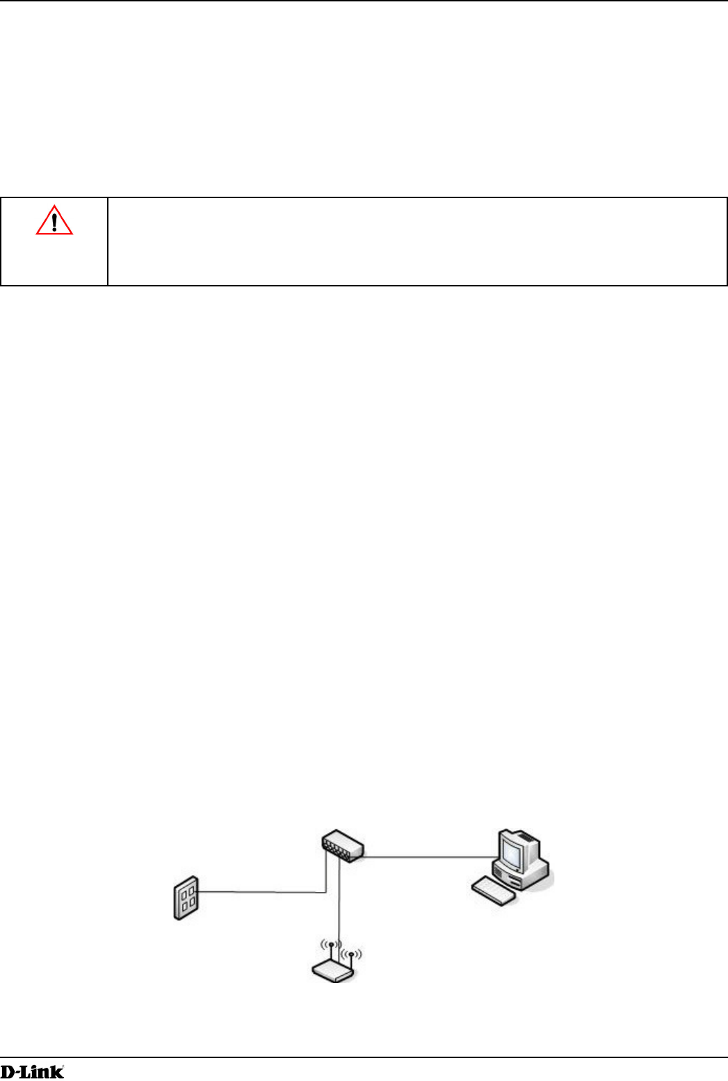
To install the UAP, use the following steps:
1.) Connect the AP to an administrative PC by using a LAN connection or a direct-cable connection.
The hub or switch you use must permit broadcast signals from the access point to reach all other devices on
the network.
Page 14
March 2012
administrative computer.
static IP address in the same subnet as the default IP address on the access point. (The default IP address for
the access point is 10.90.90.91.)
access point so that the access point is no longer connected directly to the PC but instead is connected to the
LAN (either by using a hub or directly).
It is possible to detect access points on the network with a wireless connection. However,
we strongly advise against using this method. In most environments you may have no way
of knowing whether you are actually connecting to the intended AP. Also, many of the initial
connection.
2.) Connect the power adapter to the power port on the back of the access point, and then plug the other end of the
power cord into a power outlet.
3.) Use your Web browser to log on to the UAP Administration Web pages.
If the AP did not acquire an IP address from a DHCP server on your network, enter 10.90.90.91 in the address
new IP address of the AP into the Web browser.
If you used a DHCP server and you do not know the new IP address of the AP, use the following procedures to
obtain the information:
Connect a serial cable from the administrative computer to the AP and use a terminal emulation program to
access the command-line interface (CLI).
At the login prompt, enter admin for the user name and admin for the password. At the command prompt,
enter get management.
to View the IP Address” on page 24.
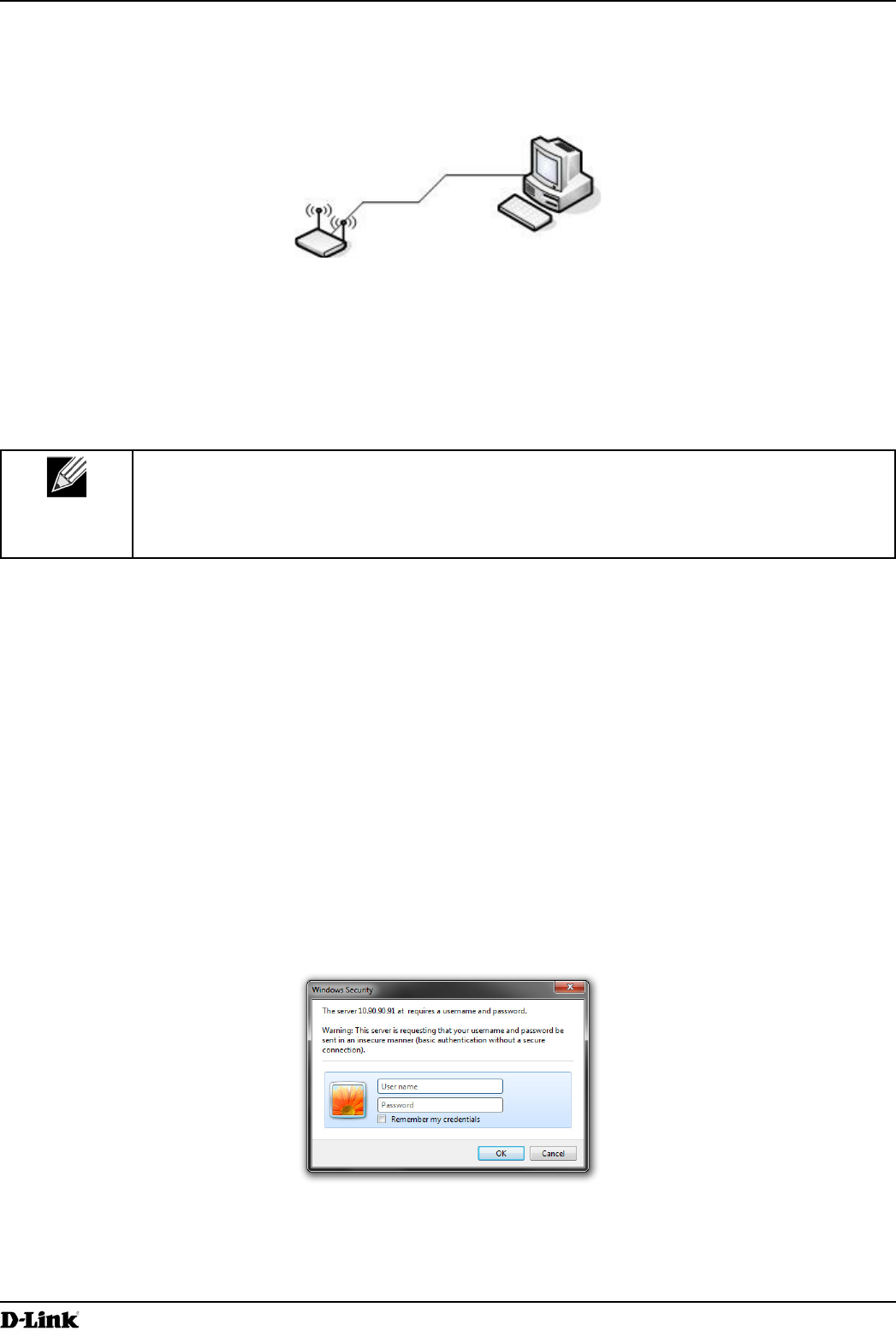
4.) When prompted, enter admin for the user name and admin for the password, then click Logon.
Figure 2 - Web UI Login Prompt
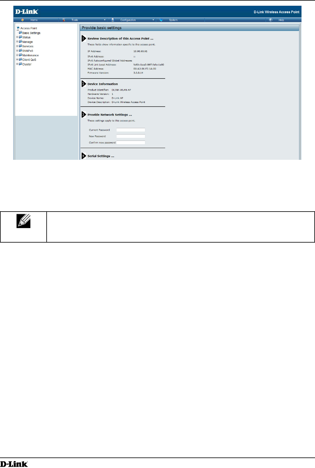
Basic Settings
shows.
Page 15
March 2012
Figure 3 -
5.) Verify the settings on the Basic Settings page.
Review access point description and provide a new administrator password for the access point if you do not
want to use the default password, which is admin.
Click the button to activate the wireless network with these new settings.
The changes you make are not saved or applied until you click Apply. Changing some
access point settings might cause the AP to stop and restart system processes. If this happens,
wireless clients will temporarily lose connectivity. We recommend that you change access point
“Basic Settings” on
page 16.
6.) If you do not have a DHCP server on the management network and do not plan to use one, you must change
the Connection Type from DHCP to Static IP.
You can either assign a new Static IP address to the AP or continue using the default address. We recommend
assigning a new Static IP address so that if you bring up another UAP on the same network, the IP address
for each AP will be unique. To change the connection type and assign a static IP address, see
18 (CLI) or 35 (Web).
7.)
the UAP in order for it to work with your network.
18
(CLI) or 35 (Web).
8.)
supplicant information on the AP.
Authentication” on page 19.

Page 16
March 2012
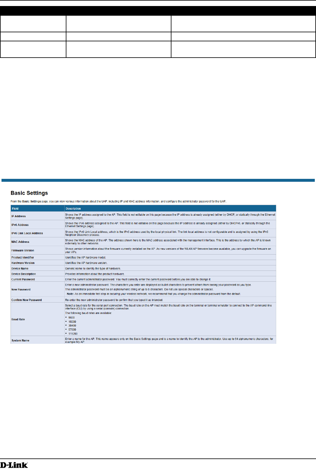
Basic Settings
Basic Settings page.
Field Description
IP Address
Settings page).
Settings page).
Shows the operational status of the static IPv6 address assigned to the management
interface of the AP. The possible values are Operational and Tentative.
Global Addresses
the AP.
Address
Shows the IPv6 Link Local address, which is the IPv6 address used by the local physical
Discovery process.
MAC Address Shows the MAC address of the AP. The address shown here is the MAC address
associated with the management interface. This is the address by which the AP is known
externally to other networks.
Firmware Version
your APs.
Hardware Version
Shows the AP serial number.
Provides information about the product hardware.
Current Password
before you are able to change it.
characters to prevent others from seeing your password as you type.
The administrator password must be an alphanumeric string of up to 8 characters. Do not
use special characters or spaces.
you change the administrator password from the default.
Password
Baud Rate Select a baud rate for the serial port connection. The baud rate on the AP must match the
baud rate on the terminal or terminal emulator to connect to the AP command-line interface
(CLI) by using a serial (console) connection.
The following baud rates are available:
9600
19200
38400
57600
115200
name to identify the AP to the administrator. Use up to 64 alphanumeric characters, for
example My AP.

Page 17
March 2012
Field Description
issues related to the AP.
Table 4 - Basic Settings Page
To connect to the AP by using the IPv6 global address or IPv6 link local address, you must enter the AP address into
your browser in a special format.
might not work with other browsers.
[2520::230:abff:fe00:2420].
To connect to the iPv6 link local address, replace the colons (:) with hyphens (-), add the interface number preceded
2420s6.ipv6-literal.net.
Using the CLI to View the IP Address
The DHCP client on the UAP is enabled by default. If you connect the UAP to a network with a DHCP server, the
AP automatically acquires an IP address. To manage the UAP by using the Administrator UI, you must enter the IP
address of the access point into a Web browser.
If a DHCP server on your network assigns an IP address to the UAP, and you do not know the IP address, use the
following steps to view the IP address of the UAP:
1.) Using a null-modem cable, connect a VT100/ANSI terminal or a workstation to the console (serial) port.
TeraTerm.
2.)
Baud rate: 115200 bps
Data bits: 8
Parity: none
Stop bit: 1
3.) Press the return key, and a login prompt should appear.
The login name is admin. The default password is admin. After a successful login, the screen shows the
()# prompt.
4.) At the login prompt, enter get management.
Information similar to the following prints to the screen.

Page 18
March 2012
Figure 4 -
By default, the DHCP client on the UAP automatically broadcasts requests for network information. If you want to
information.
The management VLAN is VLAN 1 by default. This VLAN is also the default untagged VLAN. If you already have
management VLAN on the access point.
35.
Action Commands
get host id
Set the DNS Name set host id <host_name>
set host id lab-ap
Interface
get management
Set the management VLAN ID set management vlan-id <1-4094>
View untagged VLAN information get untagged-vlan
set untagged-vlan status up
Disable the untagged VLAN set untagged-vlan status down
Set the untagged VLAN ID set untagged-vlan vlan-id <1-4094>
View the connection type get management dhcp-status

Page 19
March 2012
Action Commands
Use DHCP as the connection type set management dhcp-status up
Use a Static IP as the connection type set management dhcp-status down
Set the Static IP address set management static-ip <ip_address>
set management static-ip 10.10.12.221
Set a Subnet Mask set management static-mask <netmask>
set management static-mask 255.255.255.0
set static-ip-route gateway <ip_address>
set static-ip-route gateway 10.10.12.1
View the DNS Nameserver mode Dynamic= up
Manual=down
get host dns-via-dhcp
Set DNS Nameservers to Use Static IP Addresses
(Dynamic to Manual Mode)
set host dns-via-dhcp down
set host static-dns-1 <ip_address>
set host static-dns-2 <ip_address>
set host static-dns-1 192.168.23.45
Set DNS Nameservers to Use DHCP IP Addressing
(Manual to Dynamic Mode)
set host dns-via-dhcp up
Table 5 -
In the following example, the administrator uses the CLI to set the management VLAN ID to 123 and to disable the
DLINK-WLAN-AP# set management vlan-id 123
DLINK-WLAN-AP# set untagged-vlan status down
DLINK-WLAN-AP# get management
Property Value
--------------------------------------------
vlan-id 123
interface brtrunk
static-ip 10.90.90.91
static-mask 255.0.0.0
ip 10.90.90.91
mask 255.0.0.0
mac 00:05:5E:80:70:00
dhcp-status down
ipv6-status up
static-ipv6 ::
DLINK-WLAN-AP# get untagged-vlan
Property Value
---------------
vlan-id 1
status down
DLINK-WLAN-AP#
authentication information that the AP can supply to the authenticator.
19 for information about

Page 20
March 2012
Action Command
Table 6 -
password to test1234.
Property Value
--------------------------
status up
user wlanAP
eap-method md5
debug off
cert-present no
DLINK-WLAN-AP#
Make sure the access point is connected to the LAN and associate some wireless clients with the network. Once you
1.) Connect the access point to the LAN.
access point is already connected to the LAN. The next step is to test some wireless clients.
do the following procedures:
Disconnect the cable from the computer and the access point.
2.) Test LAN connectivity with wireless clients.
requirements for these clients, see “Wireless Client Requirements” on page 12.
3.)
Once the wireless network is up and you can connect to the AP with some wireless clients, you can add in layers
than one administrator is logged onto the Administration Web pages and making changes to the
be applied.
By default, no security is in place on the access point, so any wireless client can associate with it and access
“Virtual Access Point Settings” on page
47.

Page 21
March 2012
following default settings:
VLAN ID: 1
SSID: dlink1
Security: None
MAC Authentication Type: None
Redirect Mode: None
All other VAPs are disabled by default. The default SSID for VAPs 1–15 is ”dlinkx” where x is the VAP ID.
None for the default VAP and for each VAP that you enable.
“Virtual Access Point Settings” on page
47.
Page 22
March 2012
Section 3 - Viewing Access Point Status
Section 3 - Viewing Access Point Status
This section describes the information you can view from the tabs under the Status heading on the Administration
Web UI. This section contains the following subsections:
“Viewing Interface Status” on page 22
“Viewing Transmit and Receive Statistics” on page 25
“Viewing Associated Wireless Client Information” on page 26
“Viewing Rogue AP Detection” on page 28
“Viewing Managed AP DHCP Information” on page 31
“Viewing Radio Statistics Information” on page 33
The web-based UI images show the DWL-8600AP administration pages. Pages for the
DWL-2600AP or DWL-3600AP will display information for one radio only.
Viewing Interface Status
Interfaces tab.
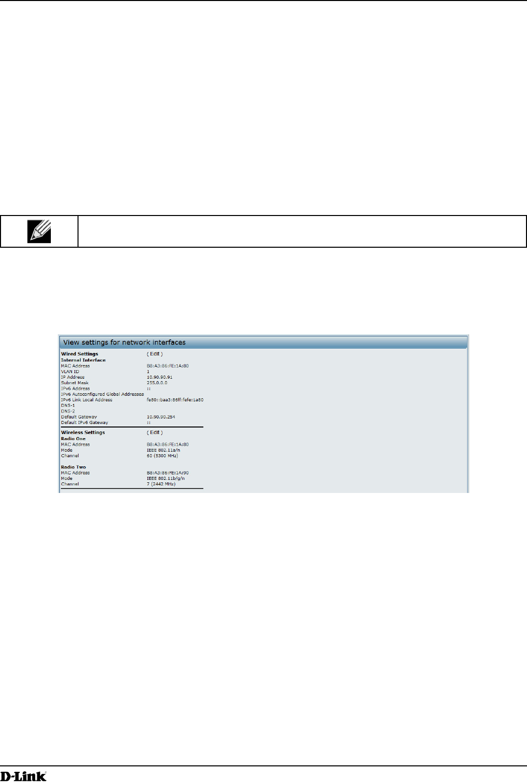
Figure 5 - Viewing Interface Status
This page displays the current settings of the UAP. It displays the Wired Settings and the Wireless Settings.
Subnet Mask, and DNS information. To change any of these settings, click the link. After you click , you are
redirected to the page.
18.
Wireless Settings
Wireless Settings section also shows the MAC address (read-only) associated with each radio interface.
To change the Radio Mode or Channel settings, click the link. After you click , you are redirected to the
Page 23
March 2012
Section 3 - Viewing Access Point Status
page.
“Wireless Settings” on page 37 and “Modifying Radio Settings”
on page 40.
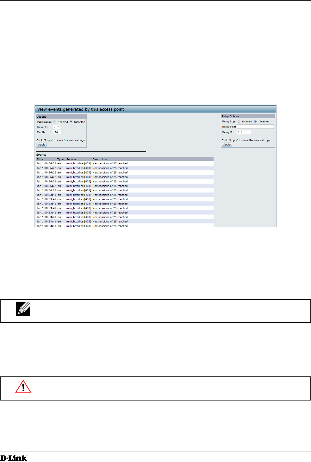
The page shows real-time system events on the AP such as wireless clients associating with the AP and being
authenticated.
To view system events, click the tab.
Figure 6 -
page, you can perform the following tasks:
View the most recent, high-level events generated by this AP.
Persistent logging to write system event logs to non-volatile memory so that the events
are not erased when the system reboots.
Set a to determine what category of log messages are displayed.
Set Depth
The AP acquires its date and time information using the network time protocol (NTP). This
reported time to your local time.
If the system unexpectedly reboots, log messages can be useful to diagnose the cause. However, log messages are
erased when the system reboots unless you enable persistent logging.
Caution!
network performance. You should only enable persistent logging to debug a problem. Make sure
page, set the persistence, severity, and depth options as described in
the following table, and then click .
Page 24
March 2012
Section 3 - Viewing Access Point Status
Field Description
Persistence Choose to save system logs to non-volatile memory so that the logs are not erased
when the AP reboots. Choose Disabled to save system logs to volatile memory. Logs in
volatile memory are deleted when the system reboots.
messages with a severity level of 3 – 7 are written to volatile memory.
0 — emergency
1 — alert
2 — critical
3 — error
4 — warning
5 — notice
6 — info
7 — debug
Depth
Table 7 - Logging Options
To apply your changes, click . Changing some settings might cause the AP to stop
and restart system processes. If this happens, wireless clients will temporarily lose connectivity.
error conditions, like dropping frames.
UAP to send syslog messages to the remote server.
Remote log server collection for AP syslog messages provides the following features:
Allows aggregation of syslog messages from multiple APs
Stores a longer history of messages than kept on a single AP
Triggers scripted management operations and alerts
The syslog process will default to use port 514. We recommend keeping this default port.
syslog is not being used by another process.
page, set the Log Relay options as described in the following
table, and then click .
Field Description
Select to allow the UAP to send log messages to a remote host. Select Disabled
to keep all log messages on the local system.
Specify the IP Address or DNS name of the remote log server.
Specify the Port number for the syslog process on the Relay Host.
The default port is 514.
Table 8 -
Page 25
March 2012
Section 3 - Viewing Access Point Status
To apply your changes, click . Changing some settings might cause the AP to stop
and restart system processes. If this happens, wireless clients will temporarily lose connectivity.
If you enabled the Log Relay Host, clicking will activate remote logging. The AP will send its kernel messages
If you disabled the Log Relay Host, clicking will disable remote logging.
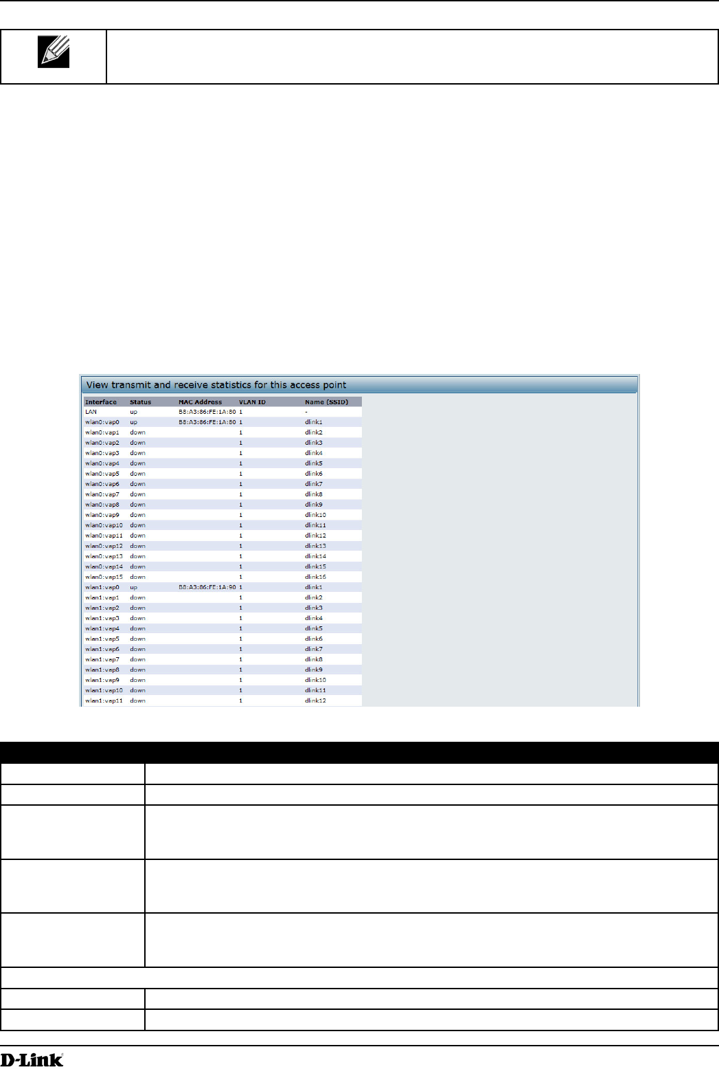
The page provides some basic information about the current AP and a real-time display of the
indicate transmit and receive totals since the reboot.
To view transmit and receive statistics for the AP, click the page.
Figure 7 -
Field Description
Interface
Status Shows whether the interface is up or down.
MAC Address
radios.
Virtual LAN (VLAN) ID.
You can use VLANs to establish multiple internal and guest networks on the same AP.
The VLAN ID is set on the VAP page. (See 60)
wireless local area network.
The SSID is set on the VAP page. (See 60)
Transmit and Receive Information
Indicates total packets sent (in Transmit table) or received (in Received table) by this AP.
Indicates total bytes sent (in Transmit table) or received (in Received table) by this AP.

Page 26
March 2012
Section 3 - Viewing Access Point Status
Field Description
Indicates total number of packets sent (in Transmit table) or received (in Received table) by
this AP that were dropped.
Indicates total number of bytes sent (in Transmit table) or received (in Received table) by
this AP that were dropped.
Indicates total errors related to sending and receiving data on this AP.
Table 9 -
Viewing Associated Wireless Client Information
To view the client stations associated with a particular access point, click the Client Associations tab.
Figure 8 - Viewing Client Association Information
station.
Client Associations page.
Field Description
wlan0vap2 means
the client is associated with Radio 1, VAP 2.
An entry of wlan0 means the client is associated with VAP 0 on Radio 1. An entry of wlan1
means the client is associated with VAP 0 on Radio 2.
Station Shows the MAC address of the associated wireless client.
Status
and association status, which is present no matter which type of security the client uses to
status.
status of clients showing on the Client Associations page will be in line with what is
expected; that is, if a client shows as authenticated to the AP, it will be able to transmit
actually not be authenticated to the AP via the second layer of security.
From Station Shows the number of packets and bytes received from the wireless client and the number of
packets and bytes that were dropped after being received.
To Station Shows the number of packets and bytes transmitted from the AP to the wireless client and
the number of packets and bytes that were dropped upon transmission.
Table 10 - Associated Clients
The page provides some basic information about the client
receive statistics shown are totals since the client association started.

Page 27
March 2012
Section 3 - Viewing Access Point Status
corporate server.
tab.
Figure 9 -
The following table describes the information provided on the
page.
Field Description
Status
Radio interface used by the client.
Station Client station MAC address.
TS Access Category (voice or video).
Direction
uplink
downlink
bidirectional
The User Priority (UP) for this TS. The UP is sent with each packet in the UP portion of the
IP header. Typical values are:
6 or 7 for voice
4 or 5 for video
Medium Time
medium.
Minor, infrequent violations are ignored.
VAP The Virtual Access Point associated with this TS client.
MAC Address The Virtual Access Point MAC address.
SSID
Statistics
Radio interface used by the client.
Station Client station MAC address.
TS Access Category (voice or video).
Direction
uplink
downlink
bidirectional
Page 28
March 2012
Section 3 - Viewing Access Point Status
Field Description
From Station Shows the number of packets and bytes received from the wireless client and the number
of packets and bytes that were dropped after being received. Also shows the number of
packets:
To Station Shows the number of packets and bytes transmitted from the AP to the wireless client and
the number of packets and bytes that were dropped upon transmission. Also shows the
number of packets:
Table 11 -
The UAP provides link integrity monitoring to continually verify its connection to each associated client. To do this,
drops off the list within 300 seconds if these data packets are not acknowledged, even if no disassociation message is
received.
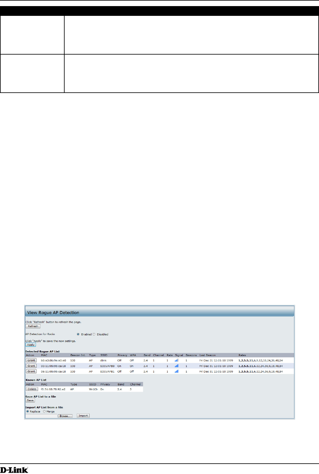
Viewing Rogue AP Detection
The status page to view Rogue AP Detection information provides real-time statistics for all APs within range of the
AP on which you are viewing the Administration Web pages. When AP detection is enabled, the radio will periodically
switch from its operating channel to scan other channels within the same band. Click Refresh to update the screen
and display the most current information.
The Rogue AP Detection page contains the following two lists:
Detected Rogue AP List — Lists all APs within range of the AP that have not been acknowledged as known APs.
clicking the Grant button associated with an AP in the Detected Rogue AP List or by appearing in an imported
AP list.
To view information about other access points on the wireless network, click the Rogue AP Detection tab.
Figure 10 -
You must enable the AP detection on a radio in order to collect information about other APs within range.
The following table describes the information provided on neighboring access points.

Page 29
March 2012
Section 3 - Viewing Access Point Status
Field Description
AP Detection for
Radio
To allow the AP radios to perform neighbor AP detection and collect information about
neighbor APs, click .
To disable neighbor AP detection on the radios, click Disabled.
If you change the AP detection mode, click to save the new settings.
Detected Rogue AP List
Action Click Grant
does not have any control over the APs on the list and cannot apply any security policies to
MAC Shows the MAC address of the neighboring AP.
Radio
wlan0 (Radio One)
wlan1 (Radio Two)
Beacon Int. Shows the Beacon interval being used by this AP.
Beacon frames are transmitted by an AP at regular intervals to announce the existence
of the wireless network. The default behavior is to send a beacon frame once every 100
milliseconds (or 10 per second).
The Beacon Interval is set on the Radio page.(See “Modifying Radio Settings” on page
40)
Indicates the type of device:
AP
Ad hoc indicates a neighboring station running in Ad hoc Mode. Stations set to ad
hoc mode communicate with each other directly, without the use of a traditional AP.
mode or an .
SSID The for the AP.
local area network. It is also referred to as the .
The SSID is set on the VAP page. (See 60)
Indicates whether there is any security on the neighboring device.
Off indicates that the Security mode on the neighboring device is set to None (no
security).
On indicates that the neighboring device has some security in place.
VAP page.
WPA Indicates whether WPA security is on or off for this AP.
Band
The number shown indicates the mode according to the following map:
2.4
5
Channel Shows the Channel on which the AP is currently broadcasting.
and receiving.
The channel is set in Radio Settings. (See “Modifying Radio Settings” on page 40)
Rate Shows the rate (in megabits per second) at which this AP is currently transmitting.
The current rate will always be one of the rates shown in Supported Rates.
Signal Indicates the strength of the radio signal emitting from this AP. If you hover the mouse
pointer over the bars, a number appears and shows the strength in decibels (dB).
Beacons
Last Beacon Shows the date and time of the last beacon received from this AP.
Rates Shows supported and basic (advertised) rate sets for the neighboring AP. Rates are shown
in megabits per second (Mbps).
All Supported Rates are listed, with Basic Rates shown in bold.
Radio Settings page. (See “Modifying Radio Settings” on
page 40)

Page 30
March 2012
Section 3 - Viewing Access Point Status
Field Description
Known AP List
Action
List by clicking the Grant button or if the MAC address of the AP appears in an AP list that
has been imported.
Delete.
does not have any control over the APs on the list and cannot apply any security policies to
MAC Shows the MAC address of the neighboring AP.
Indicates the type of device:
AP
Ad hoc indicates a neighboring station running in Ad hoc Mode. Stations set to ad
hoc mode communicate with each other directly, without the use of a traditional AP.
mode or an .
SSID The for the AP.
local area network. It is also referred to as the .
The SSID is set on the VAP page. (See 60)
Indicates whether there is any security on the neighboring device.
Off indicates that the Security mode on the neighboring device is set to None (no
security).
On indicates that the neighboring device has some security in place.
VAP page.
Band
The number shown indicates the mode according to the following map:
2.4
5
Channel Shows the Channel on which the AP is currently broadcasting.
and receiving.
The channel is set in Radio Settings. (See “Modifying Radio Settings” on page 40)
Table 12 - Rogue AP Detection
. The list contains the MAC addresses of all AP that have been added to
and view its contents.
1.)
Select the Replace
Select the Merge
2.) Click Browse
in hexadecimal format with each octet separated by colons, for example 00:11:22:33:44:55. Separate entries
3.) Click Import.
Page 31
March 2012
Section 3 - Viewing Access Point Status
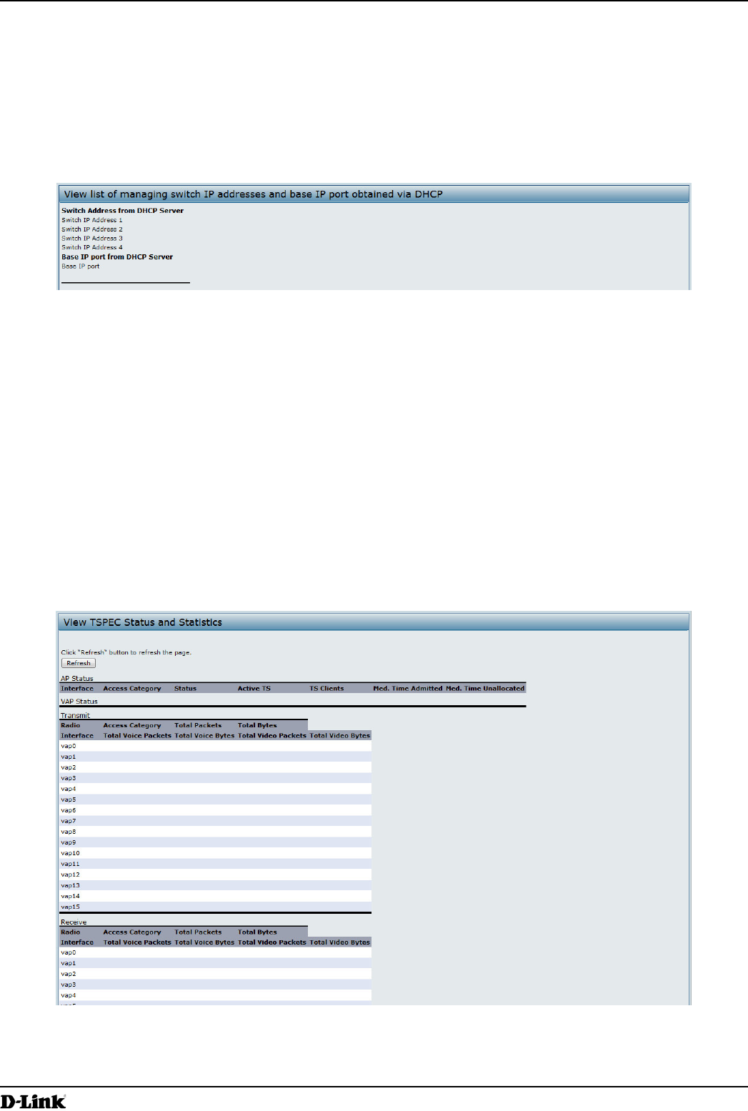
Viewing Managed AP DHCP Information
DHCP request. The Managed AP DHCP
Wireless Switches that the AP learned about from a DHCP server on your network.
Figure 11 - Managed AP DHCP Information
information, see the for the switch.
The page provides:
All of the transmit and receive statistics shown are totals since the AP was last started. If you reboot the AP, these
tab.
Figure 12 -
Page 32
March 2012
Section 3 - Viewing Access Point Status
Field Description
AP and VAP Status
Interface Indicates the name of the Radio or VAP interface.
Status
Access Category.
activity).
Category.
TS Clients
Category.
Medium Time
Admitted
Time (in 32 microsecond per second units) allocated for this Access Category over the
transmission medium to carry data. This value should be less than or equal to the maximum
bandwidth allowed over the medium for this TS.
Medium Time
Unallocated
Time (in 32 microsecond per second units) of unused bandwidth for this Access Category.
Transmit and Receive Statistics
Indicates the total number of TS packets sent (in Transmit table) or received (in Received
Indicates the total number of TS bytes sent (in Transmit table) or received (in Received
Indicates the total number of TS voice packets sent (in Transmit table) or received (in
Received table) by this AP for this VAP.
Indicates the total TS voice bytes sent (in Transmit table) or received (in Received table) by
this AP for this VAP.
Indicates the total number of TS video packets sent (in Transmit table) or received (in
Received table) by this AP for this VAP.
Indicates the total TS video bytes sent (in Transmit table) or received (in Received table) by
this AP for this VAP.
Table 13 -
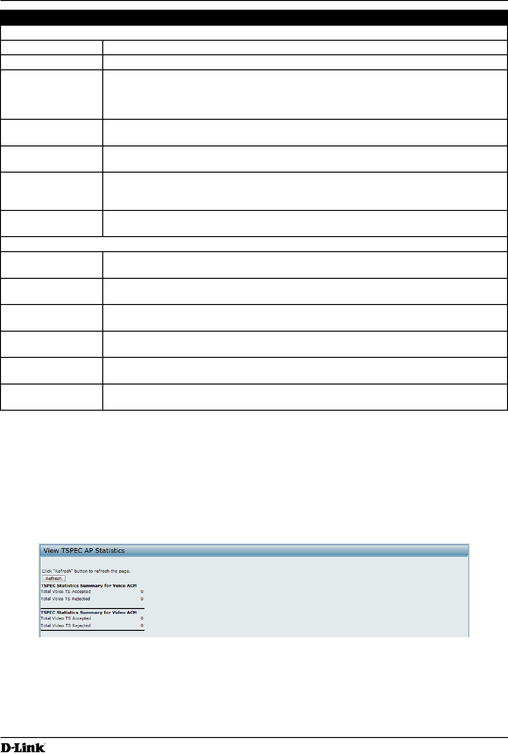
The
rejected by the AP.
tab.
Figure 13 -
Page 33
March 2012
Section 3 - Viewing Access Point Status
Field Description
ACM
Streams.
ACM
Streams.
Table 14 -
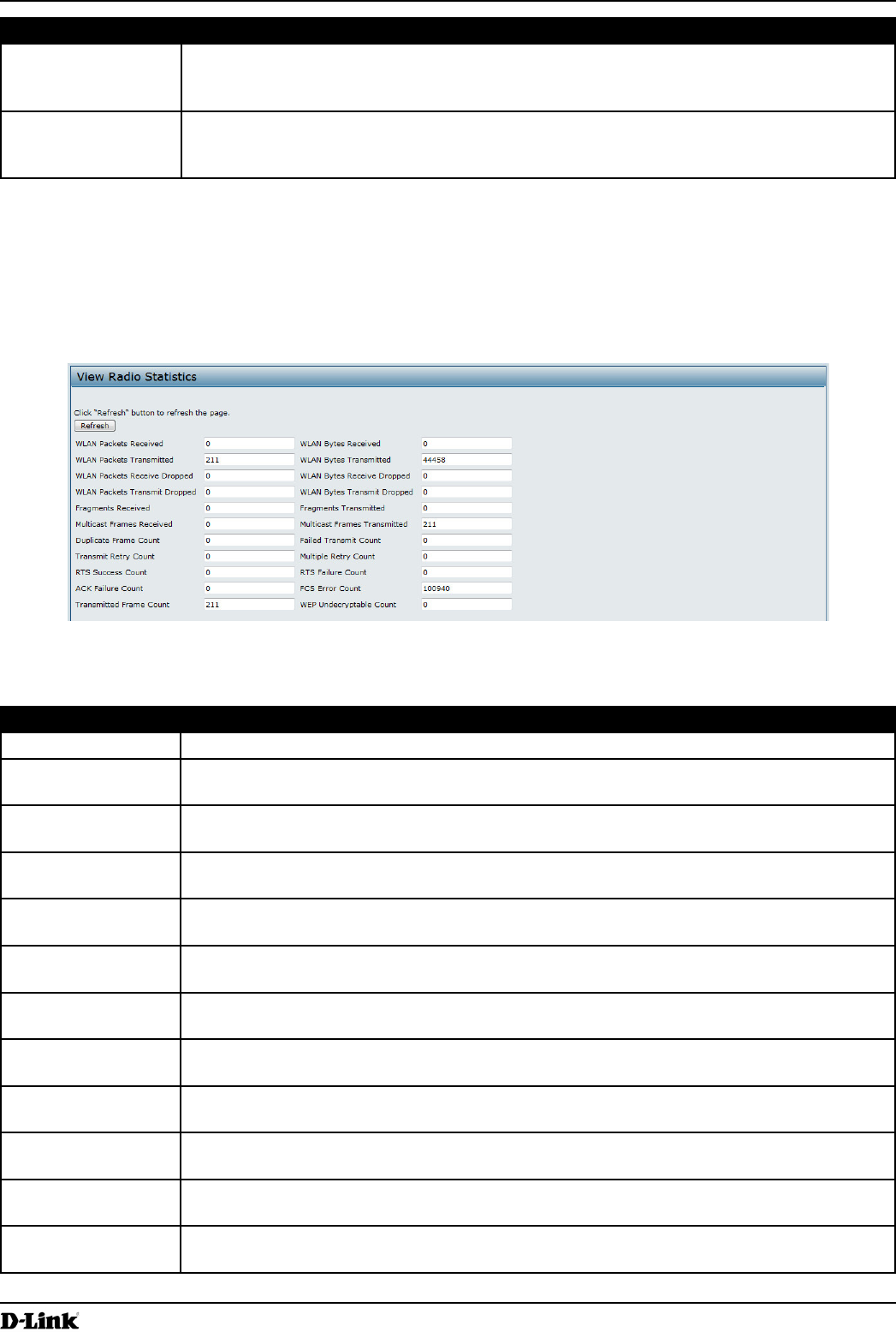
Viewing Radio Statistics Information
The Radio Statistics page provides detailed information about the packets and bytes transmitted and received on the
radio interface of this access point.
Figure 14 - View Radio Statistics
The following table describes details about the Radio Statistics information.
Field Description
Radio Choose either radio 1 or radio 2 to view statistics for the selected radio
Total packets received by the AP on this radio interface.
Total bytes received by the AP on this radio interface.
Transmitted
Total packets transmitted by the AP on this radio interface.
Transmitted
Total bytes transmitted by the AP on this radio interface.
Number of packets received by the AP on this radio interface that were dropped.
Number of bytes received by the AP on this radio interface that were dropped.
Transmit Dropped
Number of packets transmitted by the AP on this radio interface that were dropped.
Transmit Dropped
Number of bytes transmitted by the AP on this radio interface that were dropped.
Fragments
Count of successfully received MPDU frames of type data or management.
Fragments
Transmitted
Number of transmitted MPDU with an individual address or an MPDU with a multicast
address of type Data or Management.
Multicast Frames
Count of MSDU frames received with the multicast bit set in the destination MAC address.
Page 34
March 2012
Section 3 - Viewing Access Point Status
Field Description
Multicast Frames
Transmitted
Count of successfully transmitted MSDU frames where the multicast bit is set in the
destination MAC address.
Duplicate Frame
Count
Failed Transmit
Count
Number of times an MSDU is not transmitted successfully due to transmit attempts
exceeding either the short retry limit or the long retry limit.
Count
Number of times an MSDU is successfully transmitted after one or more retries.
Count
Number of times an MSDU is successfully transmitted after more than one retry.
RTS Success Count Count of CTS frames received in response to an RTS frame.
RTS Failure Count Count of CTS frames not received in response to an RTS frame.
Frames Transmitted Count of each successfully transmitted MSDU.
Count
that the frame should not have been encrypted or that frame was discarded due to the
receiving station not implementing the privacy option.
Table 15 - Radio Statistics Information
messages generated in the AP.
tab.
72.
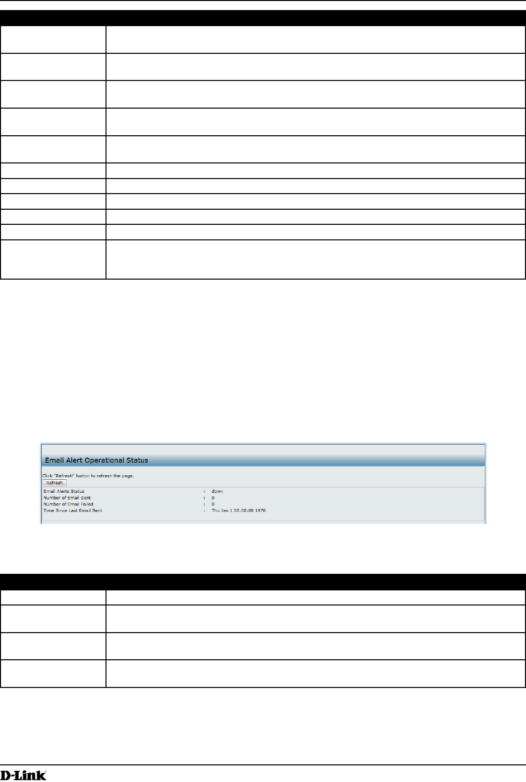
Figure 15 -
Field Description
Up or Down. The default is Down.
Sent
The total number of email sent so far. The range is an unsigned integer of 32 bits. The
default is 0.
Failed
The total number of email failures so far. The range is an unsigned integer of 32 bits. The
default is 0.
Time Since Last
The time since the last email was sent. Time format is used. The default is 00 days 00 hours
00 minutes 00 seconds.
Table 16 -
Page 35
March 2012
Section 4 - Managing the Access Point
Section 4 - Managing the Access Point
This section describes how to manage the UAP and contains the following subsections:
“Wireless Settings” on page 37
“Modifying Radio Settings” on page 40
“Scheduler Association Settings” on page 46
“Virtual Access Point Settings” on page 47
“Controlling Access by MAC Authentication” on page 59
“” on page 61
“Creating a Management Access Control List (ACL)” on page 64
Manage heading on the Administration
Web UI.
The default wired interface settings, which include DHCP and VLAN information, might not work for all networks.
By default, the DHCP client on the UAP automatically broadcasts requests for network information. If you want to
information.
The management VLAN is VLAN 1 by default. This VLAN is also the default untagged VLAN. If you already have
management VLAN on the AP.
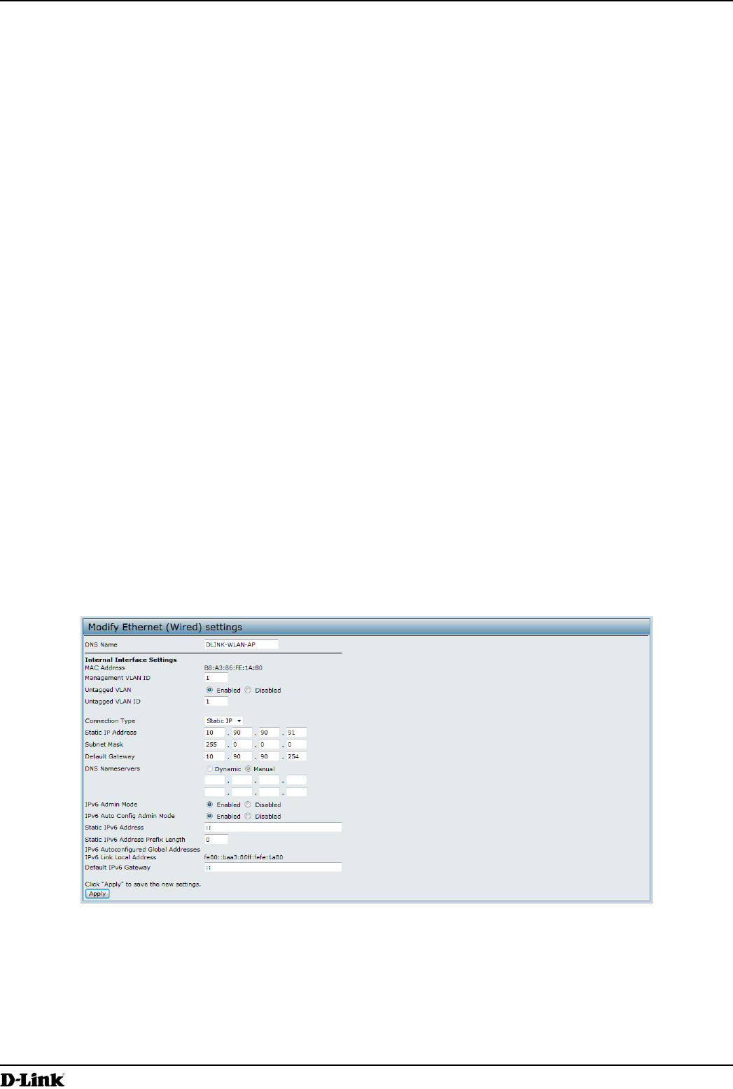
tab.
Figure 16 -
page.

Page 36
March 2012
Section 4 - Managing the Access Point
Field Description
Hostname
The hostname has the following requirements:
The length must be between 1 – 63 characters.
Upper and lower case characters, numbers, and hyphens are accepted.
hyphen.
MAC Address
ID
The management VLAN is the VLAN associated with the IP address you use to access the
AP. The default management VLAN ID is 1.
Provide a number between 1 and 4094 for the management VLAN ID.
If you select DHCP, the UAP acquires its IP address, subnet mask, DNS, and gateway
information from a DHCP server.
If you select Static IP, you must enter information in the Static IP Address, Subnet Mask,
Static IP Address
connection type.
in the text boxes.
in the text boxes.
Select the mode for the DNS.
In mode, the IP addresses for the DNS servers are assigned automatically via
In Manual mode, you must assign static IP addresses to resolve domain names.
Admin Mode
Global Addresses
If the AP has been assigned one or more IPv6 addresses automatically, the addresses are
listed.
Address
Shows the IPv6 Link Local address, which is the IPv6 address used by the local physical
Discovery process.
Table 17 -
to apply the changes and
to save the settings. Changing some settings might cause the AP to stop and restart system
processes. If this happens, wireless clients will temporarily lose connectivity. We recommend that
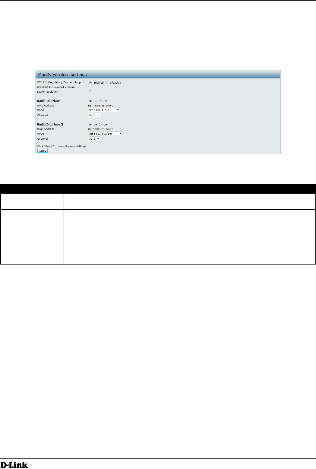
Page 37
March 2012
Section 4 - Managing the Access Point
Wireless Settings
access point (802.11 Mode and Channel) and to the network interface to the access point (MAC address for access
point and Wireless Network name, also known as SSID).
Manage > Wireless Settings tab.
Figure 17 -
Wireless Settings page.
Field Description
Specify the time interval (in seconds) for the AP to report (through the system log and SNMP
traps) associated clients that do not adhere to mandatory admission control procedures.
Radio Interface Specify whether you want the radio interface on or off.
MAC Address Indicates the Media Access Control (MAC) addresses for the interface. Dual-radio APs have
a unique MAC address for each radio.
A MAC address is a permanent, unique hardware address for any device that represents
an interface to the network. The MAC address is assigned by the manufacturer. You cannot
change the MAC address. It is provided here for informational purposes as a unique

Page 38
March 2012
Section 4 - Managing the Access Point
Field Description
Mode The Mode
The modes available depend on the country code setting and the radio selected.
Select one of the following modes for radio 1:
ranging from 6 to 54 Mbps.
supports data ranges of up to 248 Mbps and nearly twice the indoor range of 802.11
b, 802.11g, and 802.11a.
is the recommended mode for networks with 802.11n devices
compatible with legacy devices (802.11a).
Select one of the following modes for radio 2:
of the initial 802.11 PHY to include 5.5 Mbps and 11 Mbps data rates. It uses direct
extension (up to 54 Mbps) to the 802.11b PHY. It uses orthogonal frequency division
802.11g, and 802.11n devices.
is the recommended mode for networks with 802.11n devices
compatible with legacy devices (802.11b/g).
Channel Select the Channel.
The range of available channels is determined by the mode of the radio interface and the
country code setting. If you select Auto for the channel setting, the AP scans available
When automatic channel assignment is enabled on the Channel Management page for
Clustering, the channel policy for the radio is automatically set to static mode, and the Auto
the channels for the radios in the cluster.
Station Isolation To enable Station Isolation, select the check box directly beside it.
When Station Isolation is disabled, wireless clients can communicate with one another
When Station Isolation is enabled, the AP blocks communication between wireless clients
wired devices on the network, across a WDS link, and with other wireless clients associated
with a different VAP, but not among wireless clients associated with the same VAP.
Page 39
March 2012
Section 4 - Managing the Access Point
Field Description
Protocol Support
whether to enable support for the AeroScout protocol.
Options are or Disabled. The default is Disabled. When enabled, Aeroscout
determines the geographical location of 802.11 capable devices, such as STAs, APs, and
the managed access points from which it collects information. The Wireless Switch cannot
Support” on page 39.
Only AeroScout tag hardware of types T2 and T3 are explicitly supported. Other tag
models are also supported only if their implementation of the AeroScout protocol conforms
to the , version 2.1.
AeroScout tags operate only in 802.11 b/g mode. Therefore, network administrators
D-Link APs do not support this feature and never report detected APs as rogues.
Table 18 - Wireless Settings
to apply the changes and
to save the settings. Changing some settings might cause the AP to stop and restart system
processes. If this happens, wireless clients will temporarily lose connectivity. We recommend that
Using the 802.11h Wireless Mode
802.11h only works for the 802.11a band. It is not required for 802.11b or 802.11g.
If you are operating in an 802.11h enabled domain, the AP attempts to use the channel you assign. If the channel
has been blocked by a previous radar detection, or if the AP detects a radar on the channel, then the AP
automatically selects a different channel.
scanning.
two APs on the WDS link may keep changing depending on channel usage and radar interference. WDS will
Balancing” on page 60.
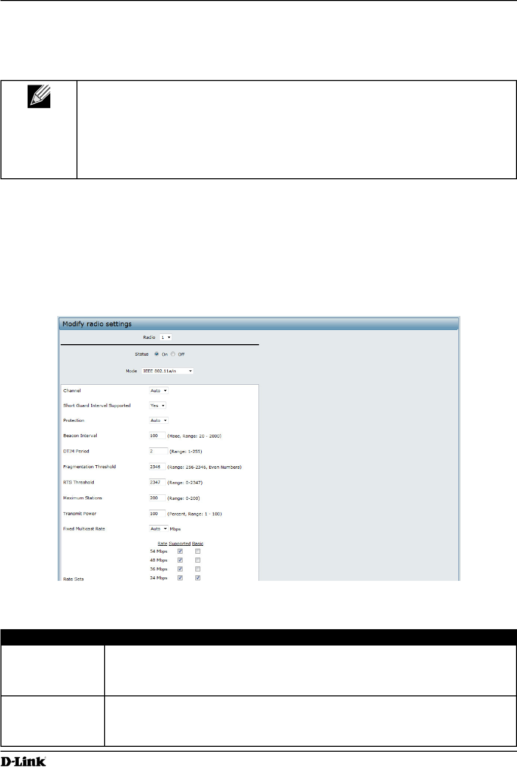
Page 40
March 2012
Section 4 - Managing the Access Point
AeroScout tags operate only in 802.11b/g mode. Therefore, network administrators who use the AeroScout tags must
The following notes apply to AeroScout product and protocol support:
D-Link does not sell AeroScout products. Contact AeroScout for AeroScout hardware,
software or deployment information.
and the access point.
receives and processes all packets detected by the radios, as opposed to processing only
packets destined to the APs BSSID. This can affect AP throughput.
Radio settings directly control the behavior of the radio devices in the AP and its interaction with the physical medium;
that is, how and what type of electromagnetic waves the AP emits.
To specify radio settings, click the Radio tab in the Manage section.
Different settings display depending on the mode you select. All settings are described in the table below.
Figure 18 -
Radio Settings page.
Field Description
Radio
(802.11b/g/n).
Specify whether you want the radio on or off by clicking On or Off.
If you turn off a radio, the AP sends disassociation frames to all the wireless clients it is
currently supporting so that the radio can be gracefully shutdown and the clients can start
the association process with other available APs.

Page 41
March 2012
Section 4 - Managing the Access Point
Field Description
Mode The Mode
The modes available depend on the country code setting and the radio selected.
Select one of the following modes for radio 1:
ranging from 6 to 54 Mbps.
supports data ranges of up to 248 Mbps and nearly twice the indoor range of 802.11
b, 802.11g, and 802.11a.
is the recommended mode for networks with 802.11n devices
compatible with legacy devices (802.11a).
Select one of the following modes for radio 2:
of the initial 802.11 PHY to include 5.5 Mbps and 11 Mbps data rates. It uses direct
extension (up to 54 Mbps) to the 802.11b PHY. It uses orthogonal frequency division
802.11g, and 802.11n devices.
is the recommended mode for networks with 802.11n devices
compatible with legacy devices (802.11b/g).
Channel Select the Channel.
The range of available channels is determined by the mode of the radio interface and the
country code setting. If you select Auto for the channel setting, the AP scans available
When automatic channel assignment is enabled on the Channel Management page for
Clustering, the channel policy for the radio is automatically set to static mode, and the Auto
the channels for the radios in the cluster.
Channel Bandwidth
channel available with other modes. The 40 MHz channel enables higher data rates but
20 MHz to restrict the use of the channel bandwidth to a 20 MHz channel.
This setting can be changed only when the channel bandwidth is set to 40 MHz. A 40 MHz
channel can be considered to consist of two 20 MHz channels that are contiguous in the
frequency domain. These two 20 MHz channels are often referred to as the and
channels. The Primary Channel is used for 802.11n clients that support only a
20 MHz channel bandwidth and for legacy clients.
Select one of the following options:
Lower — Set the Primary Channel as the lower 20 MHz channel in the 40 MHz band.
Upper — Set the Primary Channel as the upper 20 MHz channel in the 40 MHz band.

Page 42
March 2012
Section 4 - Managing the Access Point
Field Description
Supported
interval prevents Inter-Symbol and Inter-Carrier Interference (ISI, ICI). The 802.11n mode
throughput.
Select one of the following options:
Yes — The AP transmits data using a 400ns guard Interval when communicating with
clients that also support the short guard interval.
— The AP transmits data using an 800ns guard interval.
STBC Mode
Space Time Block Coding (STBC) is an 802.11n technique intended to improve the reliability
of data transmissions. The data stream is transmitted on multiple antennas so the receiving
system has a better chance of detecting at least one of the data streams.
Select one of the following options:
On — The AP transmits the same data stream on multiple antennas at the same time.
Off — The AP does not transmits the same data on multiple antennas.
Protection The protection feature contains rules to guarantee that 802.11n transmissions do not cause
interference with legacy stations or APs. By default, these protection mechanisms are
enabled (Auto). With protection enabled, protection mechanisms will be invoked if legacy
devices are within range of the AP. This causes more overhead on every transmission,
which will impact performance. However, there is no impact on performance if there are no
legacy devices within range of the AP.
You can disable (Off) these protection mechanisms; however, when 802.11n protection is
off, legacy clients or APs within range can be affected by 802.11n transmissions. The 802.11
protection feature is also available when the mode is 802.11b/g. When protection is enabled
in this mode, it protects 802.11b clients and APs from 802.11g transmissions.
This setting does not affect the ability of the client to associate with the AP.
Beacon frames are transmitted by an AP at regular intervals to announce the existence
of the wireless network. The default behavior is to send a beacon frame once every 100
milliseconds (or 10 per second).
DTIM Period Specify a DTIM period from 1 to 255 beacons.
Beacon frames. It indicates which client stations, currently sleeping in low-power mode,
have data buffered on the AP awaiting pick-up.
The DTIM period you specify indicates how often the clients served by this AP should check
for buffered data still on the AP awaiting pickup.
every 10th beacon.
Fragmentation
Threshold
Specify a number between 256 and 2,346 to set the frame size threshold in bytes.
The fragmentation threshold is a way of limiting the size of packets (frames) transmitted
over the network. If a packet exceeds the fragmentation threshold you set, the fragmentation
function is activated and the packet is sent as multiple 802.11 frames.
If the packet being transmitted is equal to or less than the threshold, fragmentation is not
used.
Setting the threshold to the largest value () effectively disables fragmentation.
However, fragmentation can help improve network performance and reliability if properly
Sending smaller frames (by using lower fragmentation threshold) might help with some
interference problems; for example, with microwave ovens.
By default, fragmentation is off. We recommend not using fragmentation unless you suspect
radio interference. The additional headers applied to each fragment increase the overhead
on the network and can greatly reduce throughput.

Page 43
March 2012
Section 4 - Managing the Access Point
Field Description
RTS Threshold Specify a Request to Send (RTS) Threshold value between 0 and 2347.
The RTS threshold indicates the number of octets in an MPDU, below which an RTS/CTS
handshake is not performed.
with a lot of clients. If you specify a low threshold value, RTS packets will be sent more
frequently. This will consume more bandwidth and reduce the throughput of the packet.
On the other hand, sending more RTS packets can help the network recover from
interference or collisions which might occur on a busy network, or on a network experiencing
electromagnetic interference.
Maximum Stations Specify the maximum number of stations allowed to access this AP at any one time.
You can enter a value between 0 and 200.
Transmit Power
The default value, which is 100%
it gives the AP a maximum broadcast range and reduces the number of APs needed.
To increase capacity of the network, place APs closer together and reduce the value of the
transmit power. This helps reduce overlap and interference among APs. A lower transmit
power setting can also keep your network more secure because weaker wireless signals are
less likely to propagate outside of the physical location of your network.
Fixed Multicast Rate
Check the transmission rate sets you want the AP to support and the basic rate sets you
want the AP to advertise:
Rates are expressed in megabits per second.
Supported Rate Sets indicate rates that the AP supports. You can check multiple rates
(click a check box to select or de-select a rate). The AP will automatically choose the
the AP.
Basic Rate Sets indicate rates that the AP will advertise to the network for the
purposes of setting up communication with other APs and client stations on the
supported rate sets.
index can be enabled and disabled independently.
Broadcast/Multicast
Rate Limiting
limiting the number of packets transmitted across the network.
By default the Multicast/Broadcast Rate Limiting option is disabled. Until you enable
Multicast/Broadcast Rate Limiting
Rate Limit
falls below this rate limit will always conform and be transmitted to the appropriate
destination. The default and maximum rate limit setting is 50 packets per second.
Rate Limit Burst
setting is 75 packets per second.
On
Radio
Off
Mode
Regulates mandatory admission control (ACM) for the voice access category. The options
are:
On
Off

Page 44
March 2012
Section 4 - Managing the Access Point
Field Description
Limit
medium using a voice AC to gain access.
Mode
Regulates mandatory admission control for the video access category. The options are:
On
Off
Limit
medium using a video AC to gain access.
Timeout
Specify the amount of time for an AP to detect an downlink TS as idle before deleting it.
Specify the amount of time for an AP to detect an uplink TS as idle before deleting it.
Mode
Select
Table 19 - Radio Settings
Use the Radio
and then
other radio.
select the Scheduler tab in the Manage
and Radios.
to achieve security and reduce power consumption. You can also use the Scheduler to allow access to VAPs for
rules are periodic in nature and are repeated every week.
A valid rule must contain all of the following parameters:
Days of the Week.
Start Time (hour and minutes).
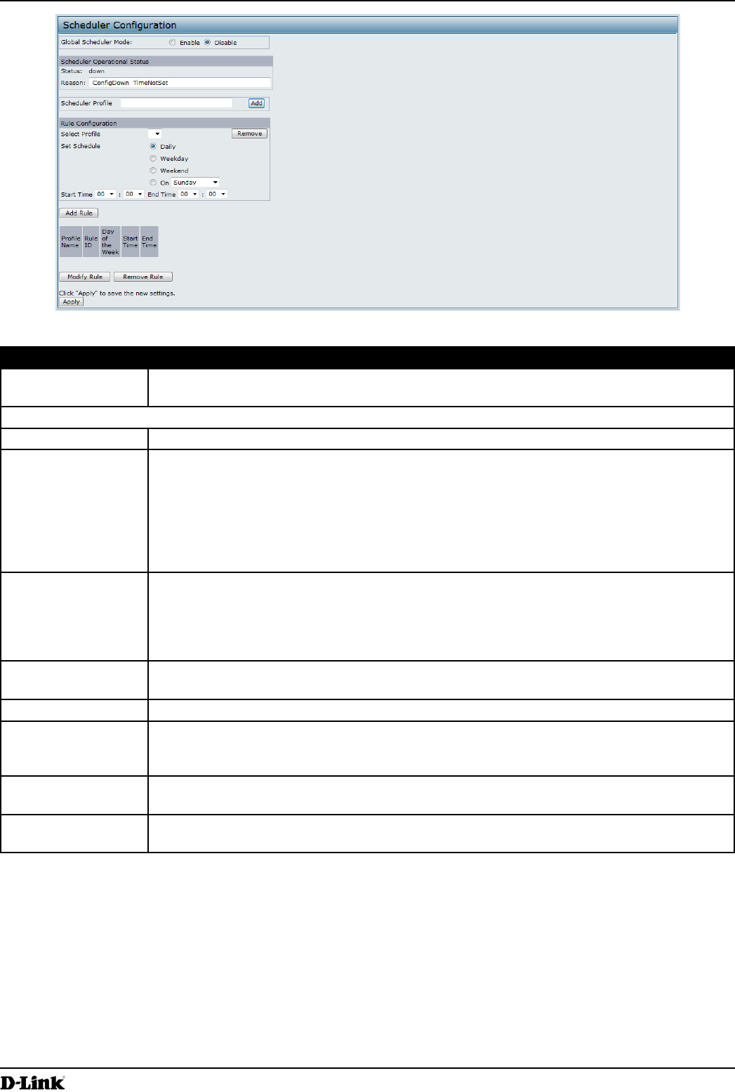
Page 45
March 2012
Section 4 - Managing the Access Point
Figure 19 -
Field Description
Global Scheduler
Mode
A global switch to enable or disable the scheduler feature. The default is Disable.
Scheduler Operational Status
Status The operational status of the Scheduler. The range is Up or Down. The default is Down.
Reason Provides additional information about the status. The reason can be one or more of the
following:
– Operational status is up.
– Operational status is down because the AP time has not been set,
either manually or by specifying an NTP server to use.
ManagedMode– Operational status is down because the AP is in managed mode.
Add
name.
periodic rule are described below.
Set Schedule The day of the week. Range is: , (Saturday
and Sunday), , , , , , , . The
default is .
Start Time The time when the radio or VAP will be operationally enabled. The time is in HH:MM 24-hour
format. The range is <00-24>:<00-59>. The default is 00:00.
The time when the radio or VAP will be operationally disabled. The time is in HH:MM 24-
hour format. The range is <00-24>:<00-59>. The default is 00:00.
Table 20 -
To change an existing rule, select the rule, update the values in the area, and click .
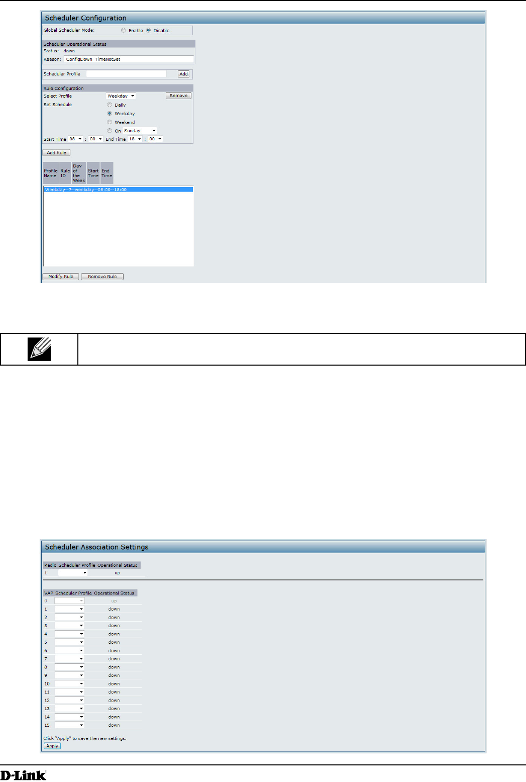
Page 46
March 2012
Section 4 - Managing the Access Point
Figure 20 -
Click
to apply the changes and to save the
settings.
Scheduler Association Settings
Scheduler Association tab in the Manage section. By default, there are no Scheduler
disabled, then all the VAPs associated to that radio are also operationally disabled irrespective of the VAP
Figure 21 - Scheduler Association Settings
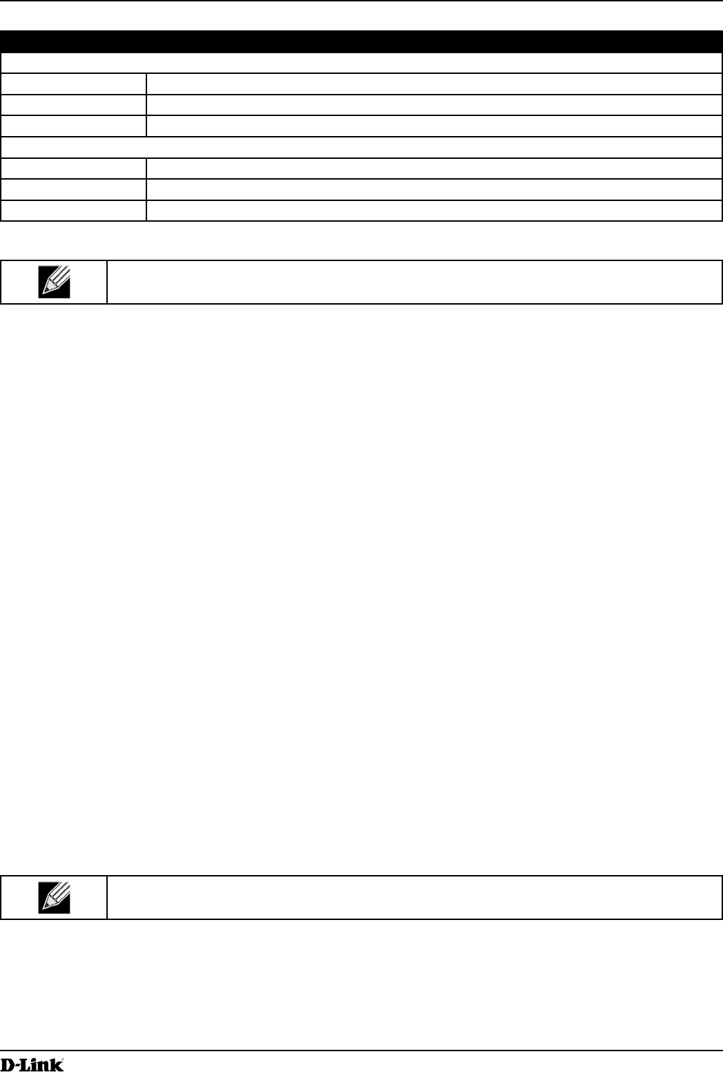
Page 47
March 2012
Section 4 - Managing the Access Point
Field Description
1 or 2
Status The operational status of the Scheduler. The range is Up or Down.
Radio
0-15
Status The operational status of the Scheduler. The range is Up or Down.
Table 21 - Scheduler Association Settings
click to apply the changes and to save the settings.
Virtual Access Point Settings
VAP tab in the Manage section.
a unique SSID. Multiple SSIDs make a single AP look like two or more APs to other systems on the network.
performance.
whether the VLAN is on the same radio or on a different radio. VAP0, which is always enabled on both radios, is
assigned to the default VLAN 1.
VAP. The external RADIUS server assigns wireless clients to the VLAN when the clients associate and authenticate.
the others act as backup servers. The network type (IPv4 or IPv6) and accounting mode are common across all
If wireless clients use a security mode that does not communicate with the RADIUS server, or if the RADIUS server
does not provide the VLAN information, you can assign a VLAN ID to each VAP. The AP assigns the VLAN to all
wireless clients that connect to the AP through that VAP.
To set up multiple VAPs, click Manage > VAP.

Page 48
March 2012
Section 4 - Managing the Access Point
Figure 22 -
VAP page.
Field Description
RADIUS IP Address
Specify the IP version that the RADIUS server uses.
and global RADIUS
address settings, but the AP contacts only the RADIUS server or servers for the address
RADIUS IP Address
Address
authentication request to the primary server. If the primary server responds to the
authentication request, the AP continues to use this RADIUS server as the primary server,
and authentication requests are sent to the address you specify.
If the
address of the RADIUS server that all VAPs use by default, for example 192.168.10.23.
If the option is selected, enter the IPv6 address of the
primary global RADIUS server, for example 2001:0db8:1234::abcd.
Address 1–3
label is RADIUS IP Address when the IPv4 RADIUS IP Address Type option is selected and
RADIUS IPv6 Address when the IPv6 RADIUS IP Address Type option is selected.
sequence. The IPv4 or IPv6 address must be valid in order for the AP to attempt to contact
the server.
The is the shared secret key for the global RADIUS server. You can use up to
63 standard alphanumeric and special characters. The key is case sensitive, and you must
displayed as “*” characters to prevent others from seeing the RADIUS key as you type.
and so on.
Accounting
Select this option to track and measure the resources a particular user has consumed
such as system time, amount of data transmitted and received, and so on.
If you enable RADIUS accounting, it is enabled for the primary RADIUS server and all
backup servers.
FailThrough
Select this option to allow the secondary RADIUS server to authenticate wireless clients
if the authentication with the primary RADIUS server is unsuccessful, or if the primary
RADIUS server is unavailable.

Page 49
March 2012
Section 4 - Managing the Access Point
Field Description
Radio
VAP
disable VAP0, you must disable the radio.
option beside the appropriate
VA P.
option beside the appropriate VAP.
ID or use a RADIUS server to assign a wireless client to a VLAN. The range for the VLAN ID
is 1 – 4094.
If you use RADIUS-based authentication for clients, you can optionally add the following
client:
“Tunnel-Type”
“Tunnel-Medium-Type”
VAP page.
more information, see 35.
SSID
characters. You can use the same SSID for multiple VAPs, or you can choose a unique
SSID for each VAP.
If you are connected as a wireless client to the same AP that you are administering,
resetting the SSID will cause you to lose connectivity to the AP. You will need to reconnect to
the new SSID after you save this new setting.
Broadcast SSID
frames. The Broadcast SSID parameter is enabled by default. When the VAP does not
broadcast its SSID, the network name is not displayed in the list of available networks on
supplicant before it is able to connect.
To enable the SSID broadcast, select the Broadcast SSID check box.
To prohibit the SSID broadcast, clear the Broadcast SSID check box.
connecting to your network, but it will not prevent even the simplest of attempts by a hacker
minimal level of protection on an otherwise exposed network (such as a guest network)
where the priority is making it easy for clients to get a connection and where no sensitive
information is available.
Select one of the following modes for this VAP:
WPA Personal
explained below.
MAC Authentication
the network. The drop-down menu for this feature allows you to select the type of MAC
Authentication to use:
Do not use MAC Authentication.
page.
Use the MAC Authentication list on the external RADIUS server.
“Controlling Access by MAC
Authentication” on page 59.
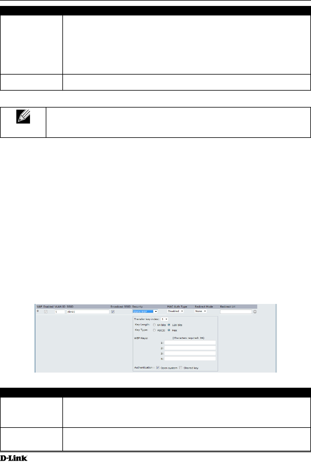
Page 50
March 2012
Section 4 - Managing the Access Point
Field Description
Redirect Mode HTTP redirect feature to redirect wireless clients to a custom Web page.
When redirect mode is enabled, the user will be redirected to the URL you specify after the
wireless client associates with an AP and the user opens a Web browser on the client to
access the Internet.
The custom Web page must be located on an external Web server and might contain
information such as the company logo and network usage policy.
The wireless client is redirected to the external Web server only once while it is
associated with the AP.
Redirect URL Specify the URL where the Web browser is to be redirected after the wireless client
Table 22 - Virtual Access Point Settings
to apply the changes and to save
the settings. Changing some settings might cause the AP to stop and restart system processes. If
this happens, wireless clients will temporarily lose connectivity. We recommend that you change
If you select
any data transferred to and from the UAP is not encrypted. This security mode can be useful during initial network
not secure.
cipher called RC4.)
Figure 23 -
Field Description
default is 1.
transmits.
Specify the length of the key by clicking one of the radio buttons:
64 bits
128 bits

Page 51
March 2012
Section 4 - Managing the Access Point
Field Description
Select the key type by clicking one of the radio buttons:
ASCII
Hex
key. The keys you enter depend on the key type selected:
ASCII — Includes upper and lower case alphabetic letters, the numeric digits, and
special symbols such as @ and #.
Authentication
Specify the authentication algorithm you want to use by choosing one of the following
options:
authentication allows any client station to associate with the AP whether
Open System, any client can associate with the AP.
Just because a client station is allowed to associate does not ensure it can exchange
and decrypt data from an AP, and to transmit readable data to the AP.
order to associate with the AP. When the authentication algorithm is set to Shared
. When you select both authentication
algorithms:
key in order to associate with the AP.
enabled) will be able to associate with the AP even if they do not have the correct
Table 23 -
The AP must have all keys used by clients for station-to-AP transmit so that it can de-code the station
transmissions.
abc123
Client stations can use different keys to transmit data to the access point. (Or they can all use the same key, but
this is less secure because it means one station can decrypt the data being sent by another.)
key index”, and then set the stations to encrypt the data they transmit using different keys. This ensures that
neighboring APs cannot decode each other’s transmissions.
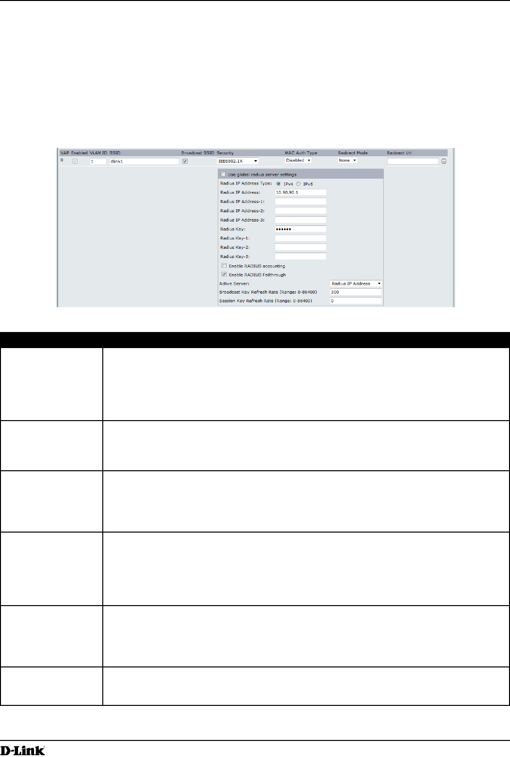
Page 52
March 2012
Section 4 - Managing the Access Point
periodically refreshed. An RC4 stream cipher is used to encrypt the frame body and cyclic redundancy checking
(CRC) of each 802.11 frame.
This mode requires the use of an external RADIUS server to authenticate users. The AP requires a RADIUS server
the AP uses.
Figure 24 -
Field Description
Use Global RADIUS
servers.
To use the global RADIUS server settings, make sure the check box is selected.
To use a separate RADIUS server for the VAP, clear the check box and enter the RADIUS
RADIUS IP Address
Specify the IP version that the RADIUS server uses.
address settings, but the AP contacts only the RADIUS server or servers for the address
RADIUS IP Address
Address
address of the RADIUS server that all VAPs use by default, for example 192.168.10.23. If
the IPv6 RADIUS IP Address Type option is selected, enter the IPv6 address of the primary
global RADIUS server, for example 2001:0db8:1234::abcd.
Address 1–3
is selected and RADIUS IPv6 Address when the IPv6 RADIUS IP Address Type option is
selected.
sequence.
The is the shared secret key for the global RADIUS server. You can use up to
63 standard alphanumeric and special characters. The key is case sensitive, and you must
displayed as “*” characters to prevent others from seeing the RADIUS key as you type.
and so on.
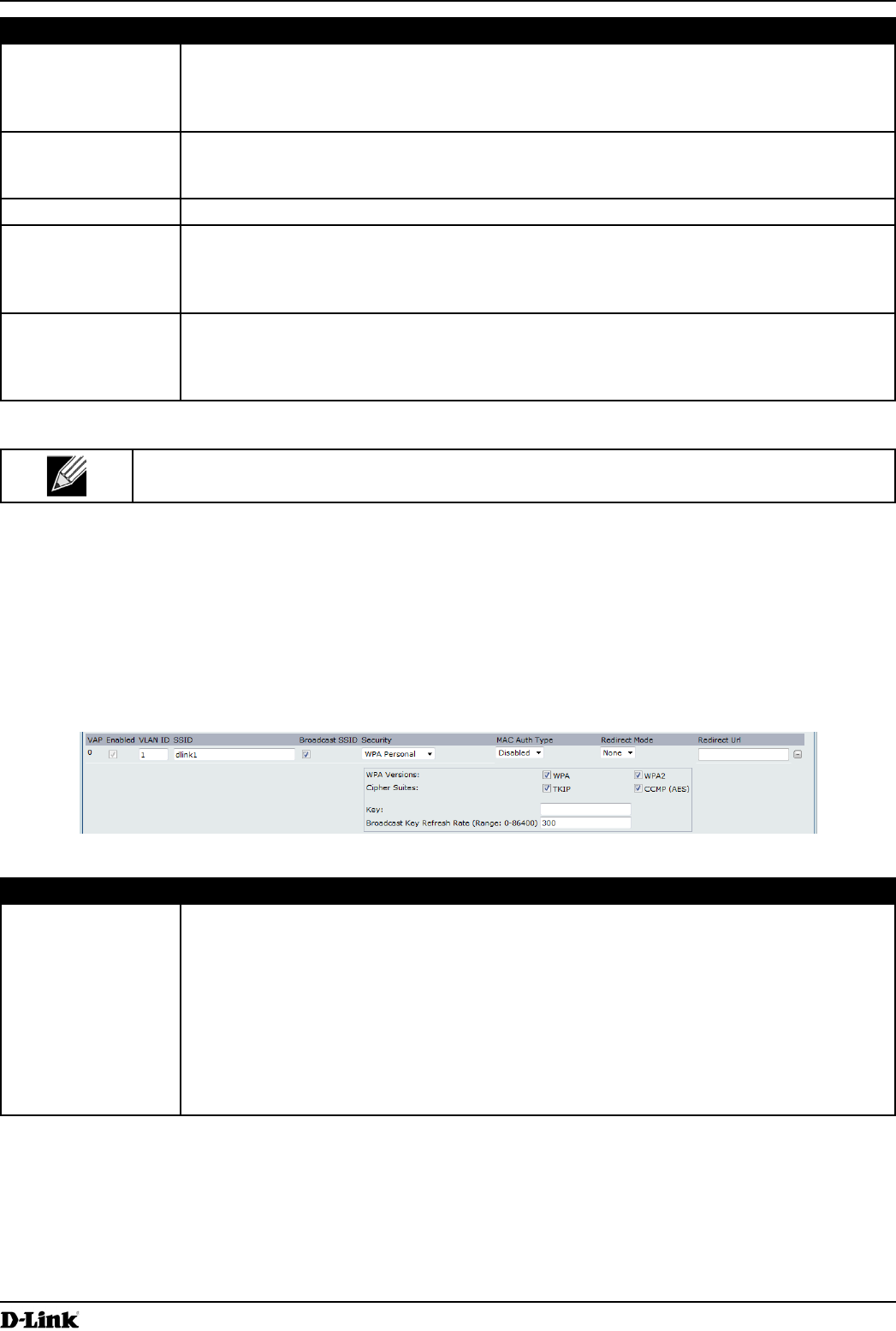
Page 53
March 2012
Section 4 - Managing the Access Point
Field Description
Accounting
Select this option to track and measure the resources a particular user has consumed
such as system time, amount of data transmitted and received, and so on.
If you enable RADIUS accounting, it is enabled for the primary RADIUS server and all
backup servers.
FailThrough
Select this option to allow the secondary RADIUS server to authenticate wireless clients if
the authentication with the primary RADIUS server is unsuccessful, or if the primary RADIUS
server is unavailable.
Refresh Rate
associated to this VAP (the default is 300).
The valid range is 0 – 86400 seconds. A value of 0 indicates that the broadcast key is not
refreshed.
Refresh Rate
client associated to the VAP.
The valid range is 0 – 86400 seconds. A value of 0 indicates that the broadcast key is not
refreshed.
Table 24 -
to apply the changes and to
save the settings.
WPA Personal
This security mode is backwards-compatible for wireless clients that support the original WPA.
Figure 25 -
Field Description
WPA Versions Select the types of client stations you want to support:
WPA. If all client stations on the network support the original WPA but none support the
newer WPA2, then select WPA.
WPA2. If all client stations on the network support WPA2, we suggest using WPA2
WPA and WPA2. If you have a mix of clients, some of which support WPA2 and others
which support only the original WPA, select both of the check boxes. This lets both
WPA and WPA2 client stations associate and authenticate, but uses the more robust
at the expense of some security.
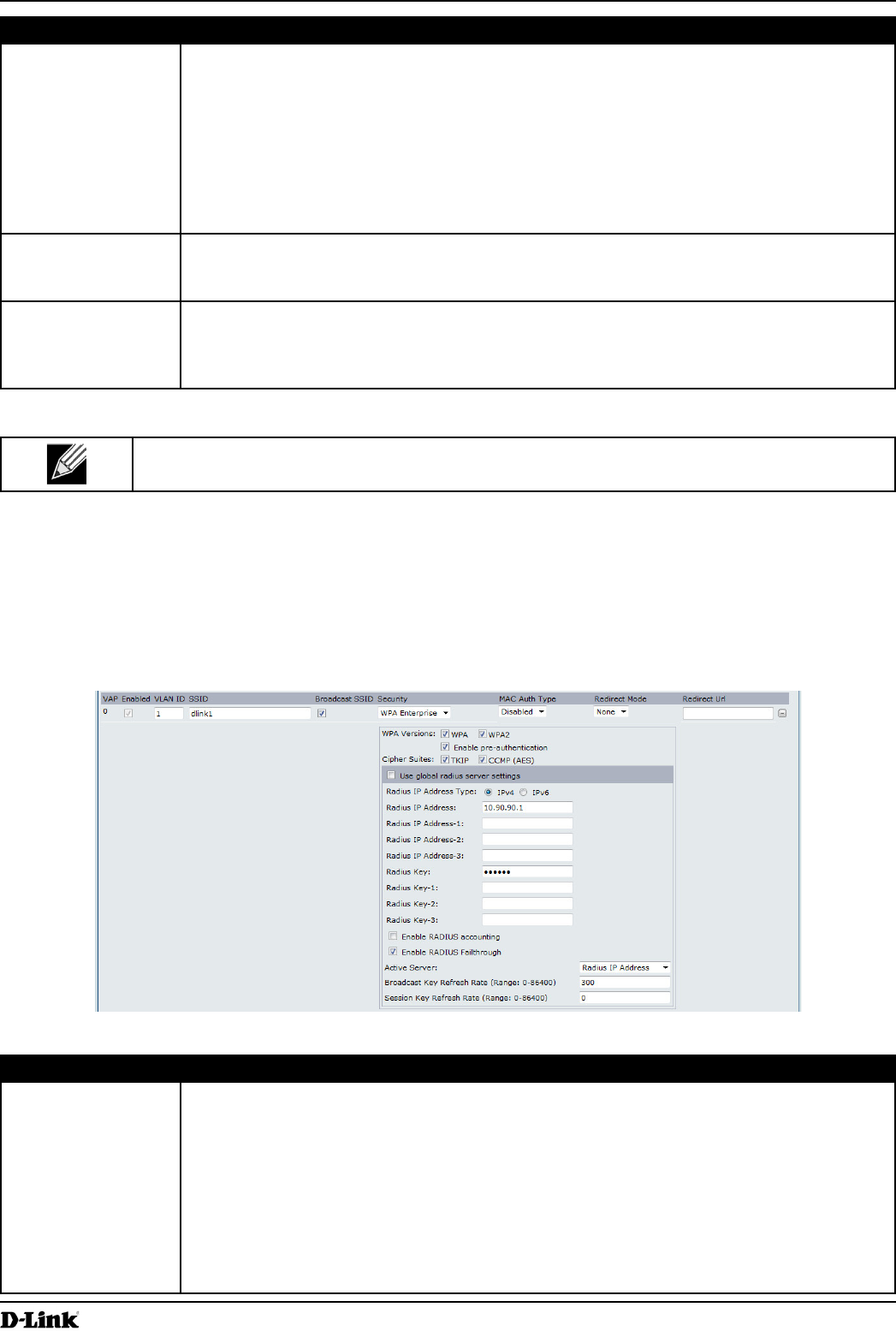
Page 54
March 2012
Section 4 - Managing the Access Point
Field Description
Cipher Suites Select the cipher suite you want to use:
and
following to be able to associate with the AP:
A valid
A valid
The
characters to a maximum of 63 characters. Acceptable characters include upper and lower
case alphabetic letters, the numeric digits, and special symbols such as @ and #.
Refresh Rate
associated to this VAP (the default is 300).
The valid range is 0–86400 seconds. A value of 0 indicates that the broadcast key is not
refreshed.
Table 25 - WPA Personal
to apply the changes and to
save the settings.
This security mode is backwards-compatible with wireless clients that support the original WPA.
Figure 26 -
Field Description
WPA Versions Select the types of client stations you want to support:
WPA. If all client stations on the network support the original WPA but none support the
newer WPA2, then select WPA.
WPA2. If all client stations on the network support WPA2, we suggest using WPA2
WPA and WPA2. If you have a mix of clients, some of which support WPA2 and others
which support only the original WPA, select both WPA and WPA2. This lets both WPA
and WPA2 client stations associate and authenticate, but uses the more robust WPA2
expense of some security.

Page 55
March 2012
Section 4 - Managing the Access Point
Field Description
authentication
If for WPA Versions you select only WPA2 or both WPA and WPA2, you can enable pre-
authentication for WPA2 clients.
Click if you want WPA2 wireless clients to send pre-
authentication packet. The pre-authentication information will be relayed from the AP
authentication for roaming clients who connect to multiple APs.
This option does not apply if you selected WPA for WPA Versions because the original WPA
does not support this feature.
Cipher Suites Select the cipher suite you want to use:
and
Use Global RADIUS
servers.
To use the global RADIUS server settings, make sure the check box is selected.
To use a separate RADIUS server for the VAP, clear the check box and enter the RADIUS
RADIUS IP Address
Specify the IP version that the RADIUS server uses.
and global RADIUS
address settings, but the AP contacts only the RADIUS server or servers for the address
RADIUS IP Address
Address
or for the primary RADIUS server for this VAP.
If the
address of the RADIUS server that all VAPs use by default, for example 192.168.10.23.
If the option is selected, enter the IPv6 address of the
primary global RADIUS server, for example 2001:0db8:1234::abcd.
Address 1–3
is selected and RADIUS IPv6 Address when the IPv6 RADIUS IP Address Type option is
selected.
sequence.
The is the shared secret key for the global RADIUS server. You can use up to
63 standard alphanumeric and special characters. The key is case sensitive, and you must
displayed as “*” characters to prevent others from seeing the RADIUS key as you type.
and so on.
Accounting
Select this option to track and measure the resources a particular user has consumed
such as system time, amount of data transmitted and received, and so on.
If you enable RADIUS accounting, it is enabled for the primary RADIUS server and all
backup servers.
FailThrough
Select this option to allow the secondary RADIUS server to authenticate wireless clients
if the authentication with the primary RADIUS server is unsuccessful, or if the primary
RADIUS server is unavailable.
Refresh Rate
associated to this VAP (the default is 300).
The valid range is 0–86400 seconds. A value of 0 indicates that the broadcast key is not
refreshed.
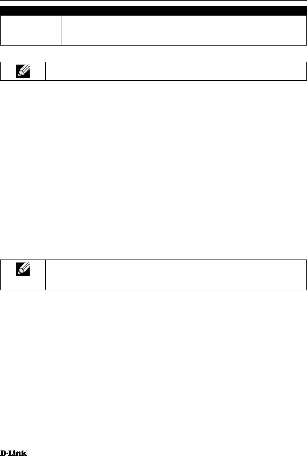
Page 56
March 2012
Section 4 - Managing the Access Point
Field Description
Refresh Rate
client associated to the VAP.
The valid range is 0–86400 seconds. A value of 0 indicates that the broadcast key is not
refreshed.
Table 26 -
to apply the changes and to
save the settings.
The Wireless Distribution System (WDS) allows you to connect multiple UAPs. With WDS, APs communicate with one
another without wires in a standardized way. This capability is critical in providing a seamless experience for roaming
clients and for managing multiple wireless networks. It can also simplify the network infrastructure by reducing the
number of links to connect.
In the point-to-point mode, the AP accepts client associations and communicates with wireless clients and other
The bridge does not add to the hop count. It functions as a simple OSI layer 2 network device.
In the point-to-multipoint bridge mode, one AP acts as the common link between multiple APs. In this mode, the
central AP accepts client associations and communicates with the clients and other repeaters. All other APs associate
only with the central AP that forwards the packets to the appropriate wireless bridge for routing purposes.
The UAP can also act as a repeater. In this mode, the AP serves as a connection between two APs that might be
too far apart to be within cell range. When acting as a repeater, the AP does not have a wired connection to the LAN
repeater, and there are no repeater mode settings. Wireless clients can still connect to an AP that is operating as a
repeater.
When you move an AP from Standalone Mode to Managed Mode, WDS is disabled.
Administrator UI, as well as Telnet, SSH, and SNMP access are disabled when the AP is in
Managed Mode.
WDS tab.
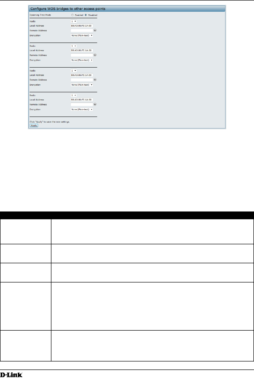
Page 57
March 2012
Section 4 - Managing the Access Point
Figure 27 -
APs participating in the WDS link.
You can have only one WDS link between any pair of APs. That is, a remote MAC address may appear only
once on the WDS page for a particular AP.
mode. (See “Modifying Radio Settings” on page 40
channel.)
Field Description
Spanning Tree
Mode
Spanning Tree Protocol (STP) prevents switching loops. STP is recommended if you
Select to use STP
Select Disabled to turn off STP links (not recommended)
Radio
Local Address Indicates the MAC addresses for this AP.
internal interface on the selected radio (Radio One on wlan0 or Radio Two on wlan1).
Remote Address Specify the MAC address of the destination AP; that is, the AP on the other end of the WDS
link to which data will be sent or handed-off and from which data will be received.
Click the drop-down arrow to the right of the Remote Address
available MAC Addresses and their associated SSIDs on the network. Select the appropriate
MAC address from the list.
The SSID displayed in the drop-down list is simply to help you identify the correct
MAC Address for the destination AP. This SSID is a separate SSID to that which you set for
the WDS link. The two do not (and should not) be the same value or name.
You can use , , or on the WDS link.
If you are unconcerned about security issues on the WDS link you may decide not to set
any type of encryption. Alternatively, if you have security concerns you can choose between
Table 27 - WDS Settings

Page 58
March 2012
Section 4 - Managing the Access Point
If you select
WDS page. All data transferred between the two APs on the WDS link will be unencrypted.
Field Description
64 bits
128 bits
ASCII
Hex
Characters
Required
Table 28 -
Field Description
SSID
different from the other SSIDs used by this AP. However, it is important that the same SSID
is also entered at the other end of the WDS link. If this SSID is not the same for both APs on
the WDS link, they will not be able to communicate and exchange data.
The SSID can be any alphanumeric combination.
entered for the AP at the other end of the WDS link. If this key is not the same for both APs,
they will not be able to communicate and exchange data.
Acceptable characters include upper and lower case alphabetic letters, the numeric digits,
and special symbols such as @ and #.
Table 29 -
to apply the changes and
to save the settings. Changing some settings might cause the AP to stop and restart system
processes. If this happens, wireless clients will temporarily lose connectivity. We recommend that
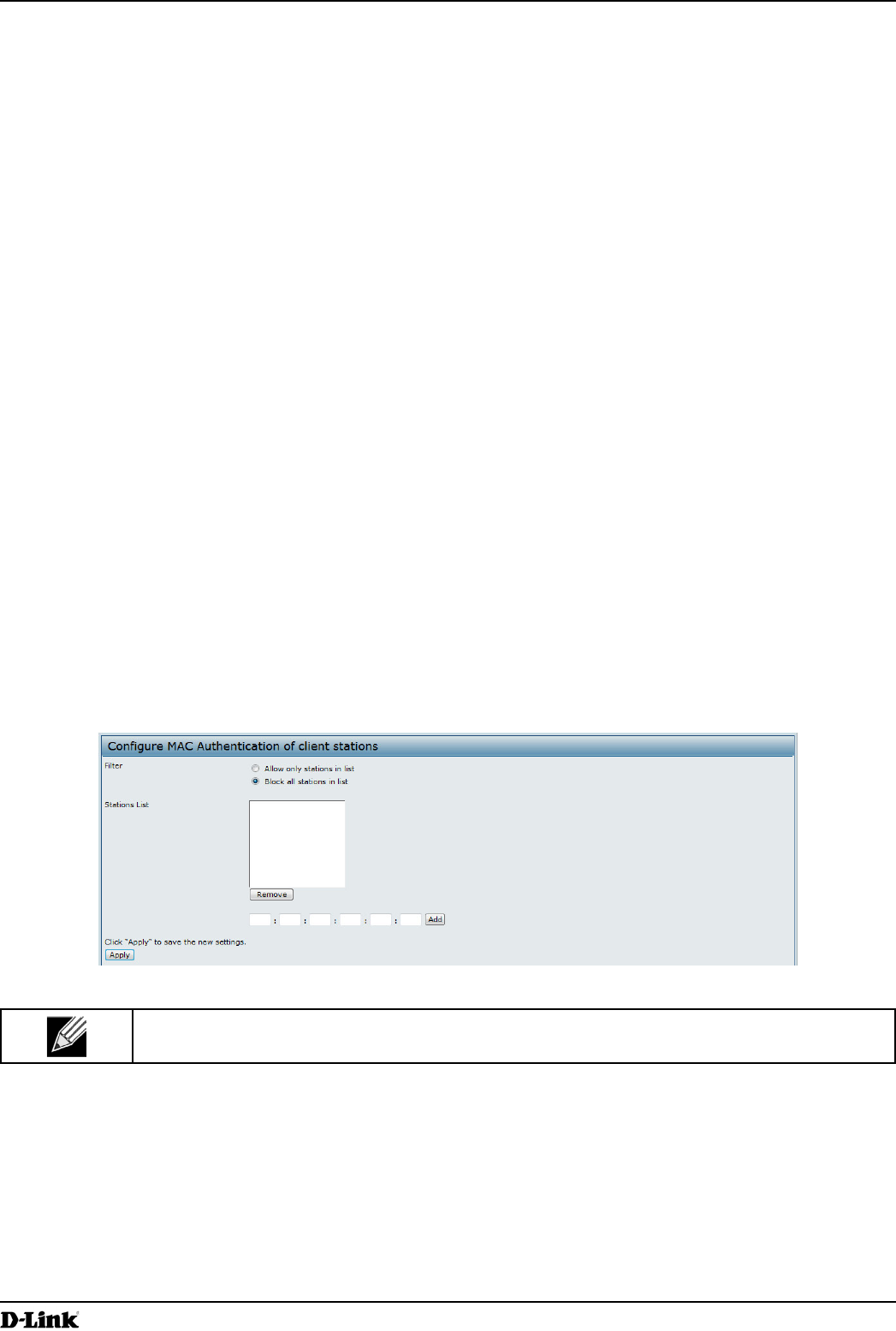
Page 59
March 2012
Section 4 - Managing the Access Point
hexadecimal digits separated by colons, for example 00:DC:BA:09:87:65
used by a wireless client has a unique MAC address.
You can use the Administrator UI on the AP or use an external RADIUS server to control access to the network
through the AP based on the MAC address of the wireless client. This feature is called MAC Authentication or MAC
the network. When a wireless client attempts to associate with an AP, the AP looks up the MAC address of the client
in the local Stations List or on the RADIUS server. If it is found, the global allow or deny setting is applied. If it is not
found, the opposite is applied.
On the VAP
locally on the MAC Authentication MAC
Authentication page determines whether the clients in the station list (local or RADIUS) can access the network
“Virtual Access Point Settings”
on page 47.
The MAC Authentication page allows you to control access to UAP based on MAC addresses. Based on how you
only client stations with a listed MAC address or access to the stations listed.
When you enable MAC Authentication and specify a list of approved MAC addresses, only clients with a listed MAC
address can access the network. If you specify MAC addresses to deny, all clients can access the network except for
the clients on the deny list.
MAC Authentication tab.
Figure 28 -
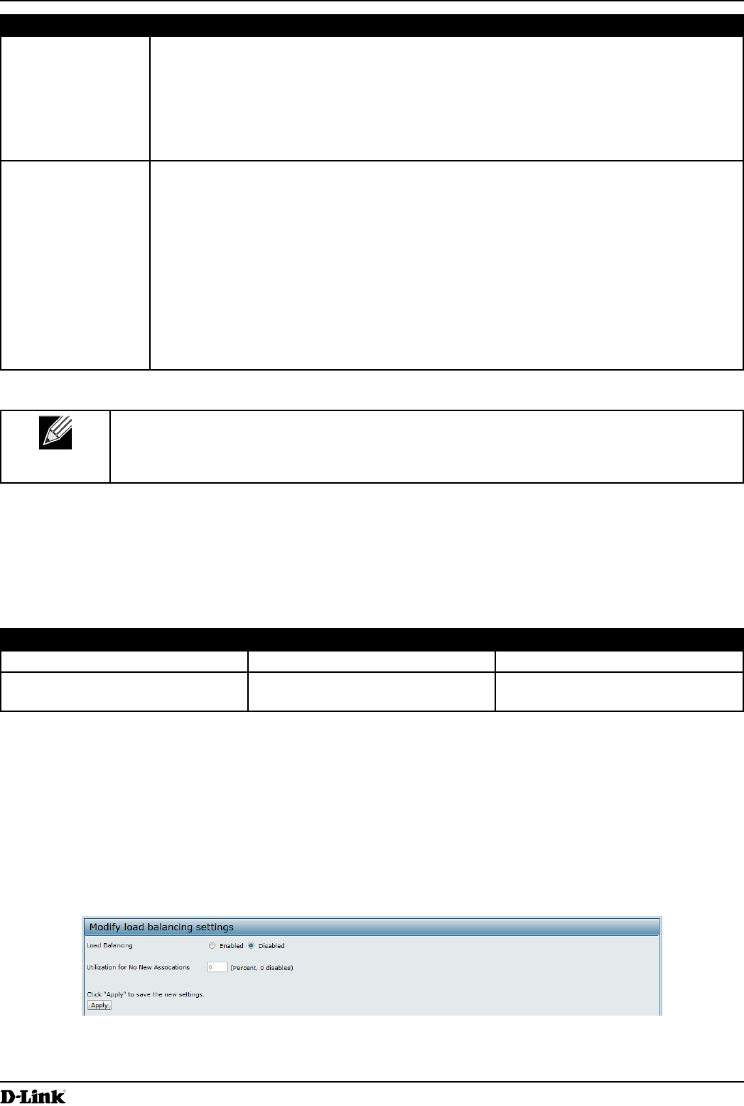
Page 60
March 2012
Section 4 - Managing the Access Point
Field Description
Filter
. Any station that is not in the Stations List is denied
access to the network through the AP.
. Only the stations that appear in the list are denied access to
the network through the AP. All other stations are permitted access.
that station list is local or on the RADIUS server.
Stations List This is the local list of clients that are either permitted or denied access to the network
through the AP. To add a MAC Address to the local Stations List, enter its 48-bit MAC
address into the lower text boxes, then click Add.
To a MAC Address from the Stations List, select its 48-bit MAC address, then click
.
If the MAC authentication type for the VAP is set to Local, the AP uses the Stations
List to permit or deny the clients access to the network. If the MAC authentication type is set
page.
Table 30 - MAC Authentication
to apply the
changes and to save the settings. Changing some settings might cause the AP to stop and
restart system processes. If this happens, wireless clients will temporarily lose connectivity. We
RADIUS server. The station list contains client MAC address entries, and the format for the list is described in the
following table.
Description Value
MAC address of the client station.
lookup a client MAC entry.
NOPASSWORD
Table 31 -
You can set network utilization thresholds on the UAP to maintain the speed and performance of the wireless network
as clients associate and disassociate with the AP. The load balancing settings apply to all supported radios.
point, click the Load Balancing
Figure 29 -