D and T FS-L4202D LCD Monitor User Manual FS L4202D Manual finally
D&T; Inc. LCD Monitor FS L4202D Manual finally
UserManual.wiki
>
D and T
>
FS L4202D User Manual
User Manual
Navigation menu
Upload a User Manual
Namespaces
Wiki Guide
HTML
PDF
Info
Views
User Manual
Discussion / Help
Navigation
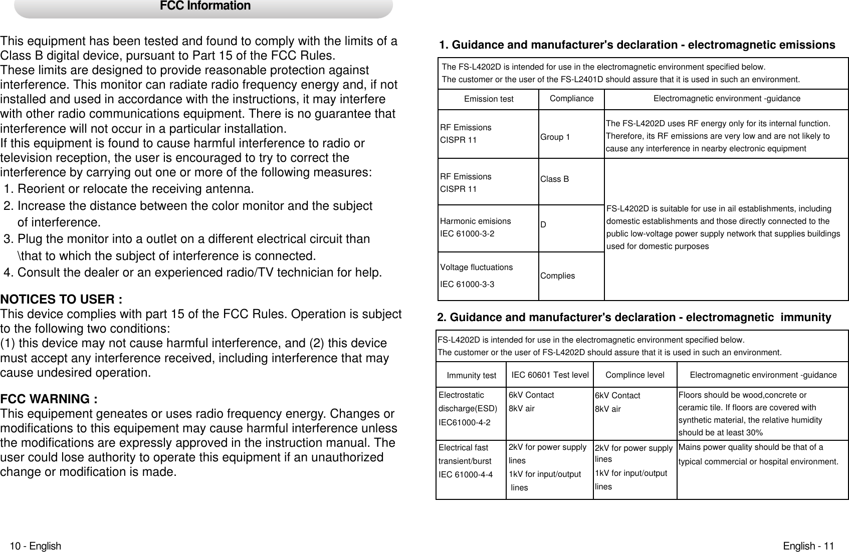
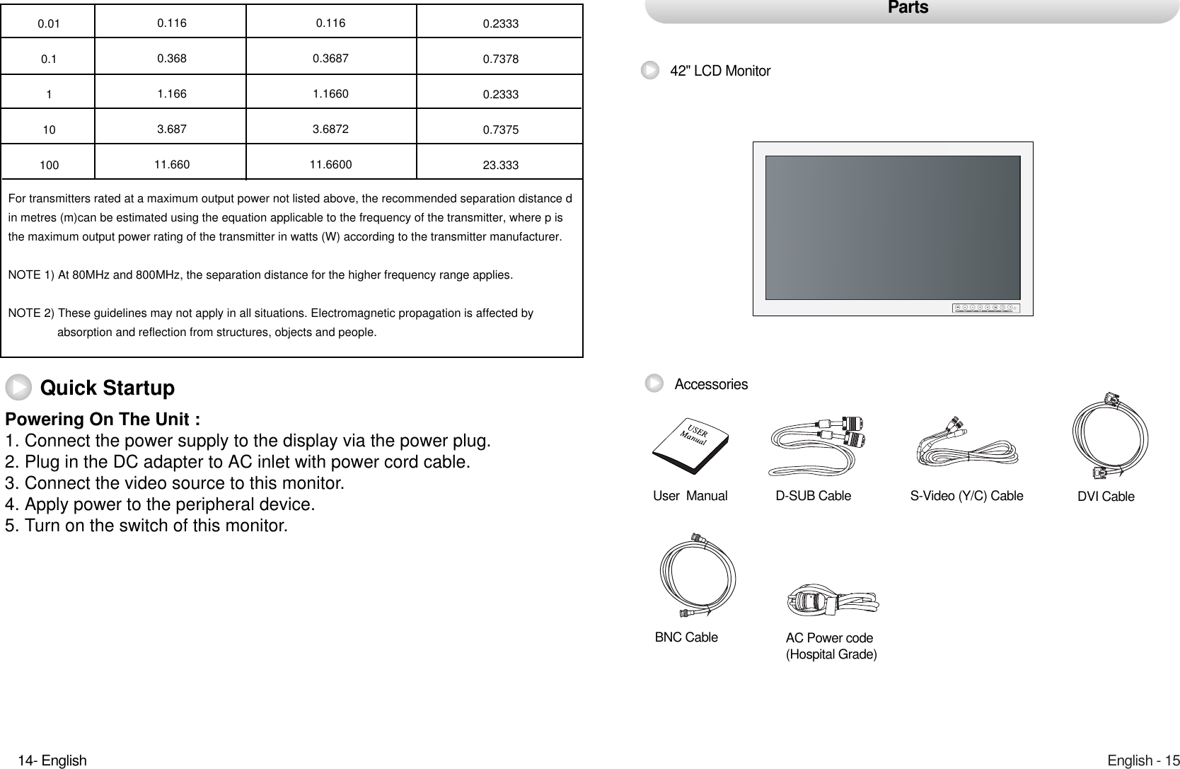
![SurgeIEC 61000-4-5Conducted RFIEC 61000-4-61kV differential mode2kV common mode3 Vrms150 kHz to 80MHz1kV differential mode2kV common mode3 Vrms150 kHz to 80MHzMains power quality should be that of a typical commercial or hospital environment.Portable and mobile RF communicationsPortable and mobile RF communicationsequipment should be used no closer to anypart of the FS-L4202D, including cables, thanthe recommended separation distance calculated from the equation applicable tothe frequency of the transmitter.Recommended separation distancewhere Pis the maximum output power rating of the transmitter in watts (W)3. Guidance and manufacturer's declaration - electromagnetic immunityImmunity testRadiated RFIEC 61000-4-3IEC 60601 Test level3 V/m80.0 MHz to 2.5 GHzComplince level 3 V/m80.0 MHz to 2.5 GHzElectromagnetic environment -guidanceRecommended separation distancewhere P is the maximum output power ratingof the transmitter in watts (W) according tothe transmitter manufacturer and d is the recommended separation distance in meters(m).Field strengths from fixed RF transmitters, asdeter-mined by an electromagnetic site survey, a should be less than the compliancelevel in each frequency range.80MHz to 800MHz80MHz to 2.5GHzFS-L4202D is intended for use in the electromagnetic environment specified below.The customer or the user of FS-L4202D should assure that it is used in such an environment.Immunity testPower frequency(50/60Hz)magnetic fieldIEC 61000-4-8Voltage dips, short interruptions and voltage variations on power supplyinput linesIEC 61000-4-11IEC 60601 Test level3.0A/m<5 % U(>95 % dip in U)for 0.5 cycle40 % U(60 % dip in U)for 5 cycle70 % U(30 % dip in U)for 25 cycle<5 % U¨‰ (<95 % dip in U¨‰ )for 5 sComplince level3.0A/m<5 % U(>95 % dip in U)for 0.5 cycle40 % U(60 % dip in U)for 5 cycle70 % U(30 % dip in U)for 25 cycle<5 % U(<95 % dip in U)for 5 sElectromagnetic environment -guidancePower frequency magnetic fields should be at levels characteristic of a typical location in a typical commercial or hospital environment.Mains power quaility shouldbe that of a typical commercial or hospitalenvironment. If the user of FS-L4202Drequires continued operation during power mains interruptions, it is recommended that FS-L4202 be poweredfrom an uninterruptible power supply or a batteryNOTE : Uis the A.C. mains voltage prior to application of the test level.4. Recommended separation distances between portable and mobileRF communications equipment and the FS-L4202D- The is intended for use in an electromagnetic environment in which radiated RF disturbances are controlled. The customer or the user of the FS-L4202D can help- Prevent electromagnetic interference by maintaining a minimum distance between portable and mobile- RF communications equipment (transmitters) and the FS-L4202D as recommended below,according to the maximum output power of the communications equipment.150kHz to 80MHz V1=3VrmsRated maximum output power of tr ansmitter [W]Separation distance according to frequency of transmitter[m]80MHz to 800MHz E1=3V/m800MHz to 2.5GHzE1=3V/mEnglish - 1312- English](https://usermanual.wiki/D-and-T/FS-L4202D/User-Guide-841097-Page-8.png)