D and T FS-L4202D LCD Monitor User Manual FS L4202D Manual finally
D&T; Inc. LCD Monitor FS L4202D Manual finally
D and T >
User Manual
MEDIC
MEDICAL LCD MONIT
AL LCD MONITOR
OR
USER'S GUIDE
FS-L4202D
FS-L4202D(
(42" )
42" )

English - 1
Symbol Definitions 2
Safety Instructions 4
Caution 7
FCC Information 10
Parts 15
Connector 16
Mechanical Product Drawing 17
Control 18
Power mangement 21
Adjust OSD Menu 22
Stansard Signal table 25
Signal connector Pin Assignments 26
Specification 29
Table of Contents
English - 32 - English
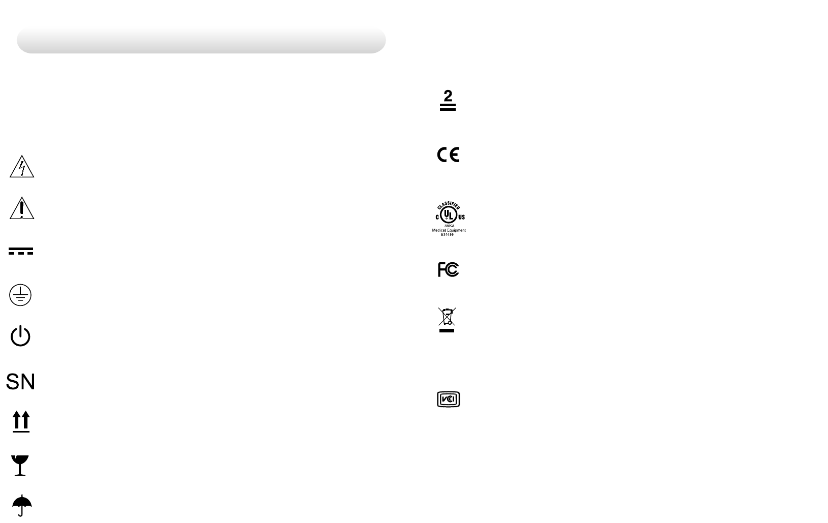
Symbol Definitions
The following symbols appear on the product. its labeling, or the
product packing. Each symbol carries a special definition, as defined
below
Dangerous : High Voltage.
Consult accompanying documents.
Direct Current.
lndicates protective earth ground.
DC Power control switch.
Serial Number.
Top-Bottom.
Fragile.
Maximum Stacking.
Indicats proof of conformity to applicable European Econmic
Community Council directives and to harmonzed standards
published in the official journal of the European Communities.
Medical Equipment is in accordance with UL 60601-1 and
CAN/CSA C22.2 No.601.1 in regards to electric shock, fire
hazards, and mechanical hazards.
Tested to comply with FCC Class B standards.
This symbol indicates that the waste of electronic
equipment must not be disposed as unsorted municipal waste
and must be collected separately. Please contact the
manufacturer or other authorized disposal company to
decommission your equipement.
Do not get wet.
Tested to comply with VCCI Class B standards.

Safety Instructions
On Safety
1. Before connecting the AC power cord to the DC adapter outlet make
sure the voltage designation of the DC adapter corresponds to the
local electrical supply.
2. Never insert anything metallic into the cabinet openings of the Liquid
Crystal Display(LCD) monitor. doing so may create the danger of
electric shock.
3. To reduce the risk of electric shock, do not remove cover.
No user-serviceable parts inside. Only a qualified technician should
open the case of the LCD monitor.
4. Never use your LCD monitor if the power cord has been damaged.
Do not allow anything to rst on the power cord, and keep the cord
away from areas where people can trip over it.
5. Be sure to hold the plug, not the cord,when disconnecting the
LCD monitor from am electric socket.
6. Unplug your LCD monitor when it is going to be left unused for an
extended period of time.
7.Unplug your LCD monitor from the AC outlet before any service.
8. if your LCD monitor does not operate normally-in particular, if there
are any unusual sounds or smells coming from it-unplug it
immediately am authorized dealer or service center.
Warning
Do not to touch signal input,signal output or other connectors, and the
patient simultaneously.
Warning
Extrnal equipment intended for connection to signal input, signal output
or other connectors, shall comply with relevant IEC
standard(e.g.,IEC60950 for IT equipment and IEC60601 series for
medical electrical equipment).
In addition, all such combination-system-shall comply with the
standard IEC 60601-1-1, safety requirements for medical electrical
systems. Any person who connectors has formed at system and is
therefore responsible for the system to comply with the requirements of
IEC 60601-1-1.
if,in doubt, contact qualified technician or your local representative.
On installation
1. Openings in the LCD monitor cabinet are provided for ventilation.
To prevent overheating, these openings should not be blocked or
covered. if you put the LCD monitor in a bookcase or some other
enclosed space, be sure to provide adequate ventilation.
2. Put your LCD monitor in a location with low humidity and a minimum
of dust.
3. Do not exepose the LCD monitor to rain or use it near water
(in kitchens, near swimming pools, etc.). if the LCD monitor
accidentally gets wet, unplug it and contact an authorized dealer
immediately.You can clean the LCD monitor with a damp cloth if
necessary, but be sure to unplug the LCD monitor first.
5. Locate your LCD monitor near an easily accessible AC outlet.
6. High temperature can cause problems. Don't use your LCD
monitor in direct sunlight and keep it away from heaters, stoves,
fireplaces, and sources of heat.
English - 54 - English
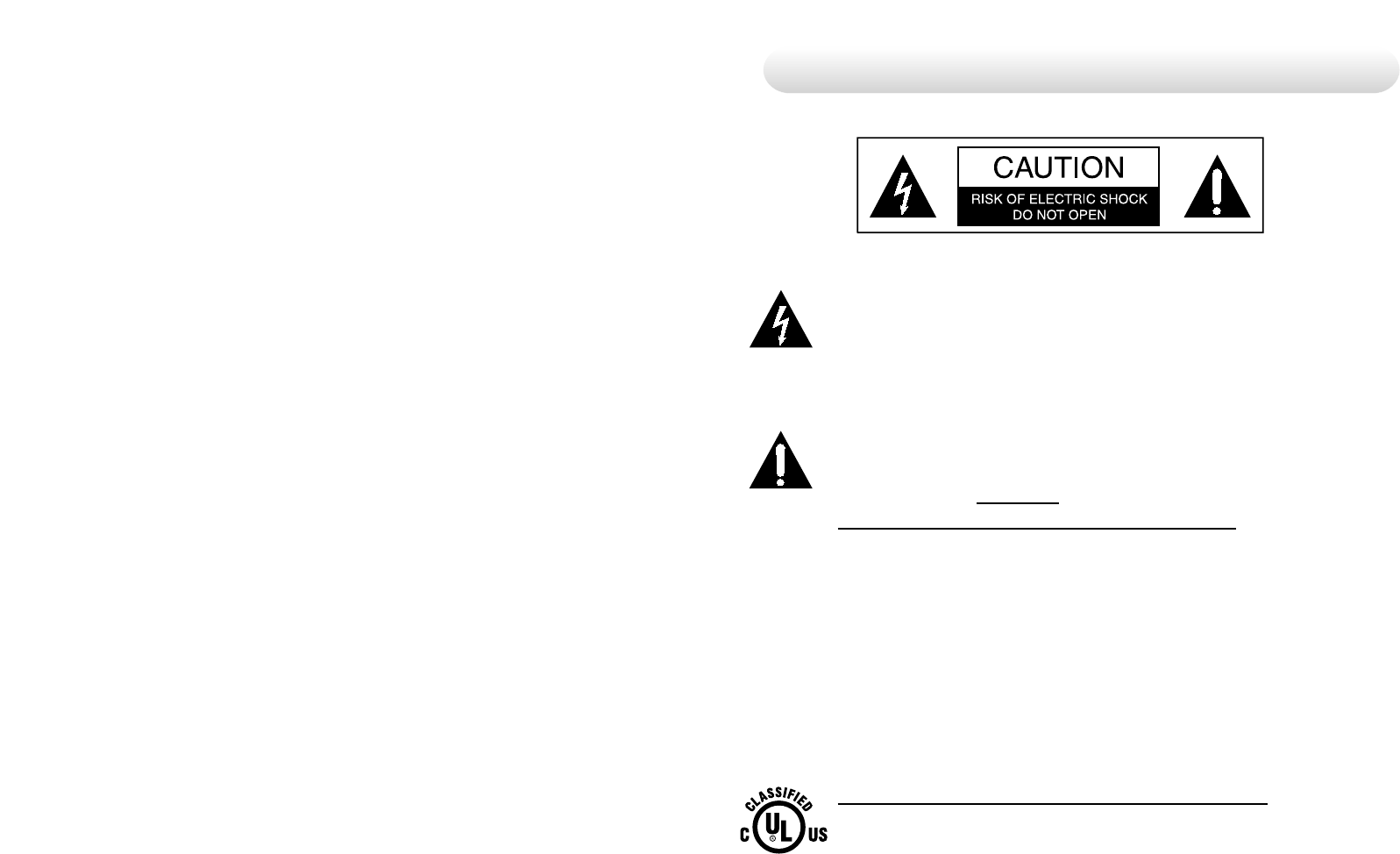
This symbol alerts the user that important literature
concerning the operation of this unit has been included.
Therefore, it should be read carefully in order to avoid potential
problems.
This symbol warms user that un-insulated voltage within the
unit the may have sufficient magnitude to cause
electrical shock. Therefore, it is dangerous to make
contact with any part inside the unit. To reduce the risk of
electric shock, DO NOT remove cover (or back).
There are no user serviceable parts inside. Refer servicing to
qualified service personal.
CAUTION
Environmental Conditions for transport and Storage
- Temperature range within -20°C to 60°C
- Relative humidity range 10% to 85%
Atrnospheric pressure range within 500 to 1060hPa.
Intended Use
- This TFT-LCD Monitor is as accessory intended for use with
Medical Equipment to display alpha, numerical and graphical data.
English - 76 - English
To prevent fire or shock hazards, do not expose this unit to
rain or moisture. Also, do not use this unit's polarized plug
with an extension cord receptacle or other outlets unless the
prongs can be fully inserted. The display is designed to meet the
medical safety requirements for a patient vicinity device.
This device may not be used in connection with life support
equipment.
Underwriters Laboratories (UL) Classification:
UL safety Compliance:
This LCD monitor is U.L. Classified WITH RESPECT TO
ELECTRIC SHOCK, FIRE AND MECHANICAL
HAZARDS ONLY IN ACCORDANCE WITH UL 60601-
1/CAN/CSA C22.2 NO. 601.1

English - 98 - English
Servicing
Do not attempt to service the apparatus yourself as opening or
removing covers may expose you to dangerous voltages or other
hazards, and will void the warranty. Refer all servicing to qualified
service personnel.
Unplug the apparatus from its power source and refer servicing to
qualified personnel under the following conditions:
If the power cord or plug is damaged or frayed.
If liquid has been spilled into the apparatus.
If objects have fallen into the apparatus.
If the apparatus has been exposed to rain or moisture
If the apparatus has been subjected to excessive shock by being
dropped.
If the cabinet has been damaged.
If the apparatus seems to be overheated.
If the apparatus emits smoke or abnormal odor.
If the apparatus fails to operate in accordance with the operating
instructions.
Accessories
Use only accessories specified by the manufacturer, or sold with the
apparatus.
Classification
- Protection against electric shock : Class I
- Applied Parts : No Applied Parts
- Protection against harmful ingress of Eater : IPX0
- Degree of safety in the presence of flammable anesthetics mixture
with air or with oxygen or with nitrous oxide.
Not suitable for use in the presence of a flammable anesthetics
mixture with oxygen or with nitrous oxide.
- Mode of operation : Continuous.
Recycling :
Follow local governing ordinances and recycling plans
regarding the recycling or disposal of this requirement.
Cleaning Instructions :
Follow your hospital protocol for the handling of blood and
body fluids. Clean the display with a diluted mixture of
mild detergent and water. Use a soft towel or swab.
Use of certain cleaning agnts may cause degrandation to
the labels and plastic components of the product.
Consult cleanser manufacturer to see if agent is compatible
with it. Do not allow liquid enter the display.
EEC Safety Compliance:
This display unit meets the requirements of EN-60601-1 so as
to conform to the Medical Device Directive 93/42/EEC
(general safety information).
The monitor should be powered from a center tapped circuit when used
in the US at voltages over 120 volts. Monitor is intended for continuous
operation.(Using Plug for US: 120V rating -5-15P tYPE, 230V rating-6-
15P type)
FCC Information
This equipment has been tested and found to comply with the limits of a
Class B digital device, pursuant to Part 15 of the FCC Rules.
These limits are designed to provide reasonable protection against
interference. This monitor can radiate radio frequency energy and, if not
installed and used in accordance with the instructions, it may interfere
with other radio communications equipment. There is no guarantee that
interference will not occur in a particular installation.
If this equipment is found to cause harmful interference to radio or
television reception, the user is encouraged to try to correct the
interference by carrying out one or more of the following measures:
1. Reorient or relocate the receiving antenna.
2. Increase the distance between the color monitor and the subject
of interference.
3. Plug the monitor into a outlet on a different electrical circuit than
\that to which the subject of interference is connected.
4. Consult the dealer or an experienced radio/TV technician for help.
NOTICES TO USER :
This device complies with part 15 of the FCC Rules. Operation is subject
to the following two conditions:
(1) this device may not cause harmful interference, and (2) this device
must accept any interference received, including interference that may
cause undesired operation.
FCC WARNING :
This equipement geneates or uses radio frequency energy. Changes or
modifications to this equipement may cause harmful interference unless
the modifications are expressly approved in the instruction manual. The
user could lose authority to operate this equipment if an unauthorized
change or modification is made.
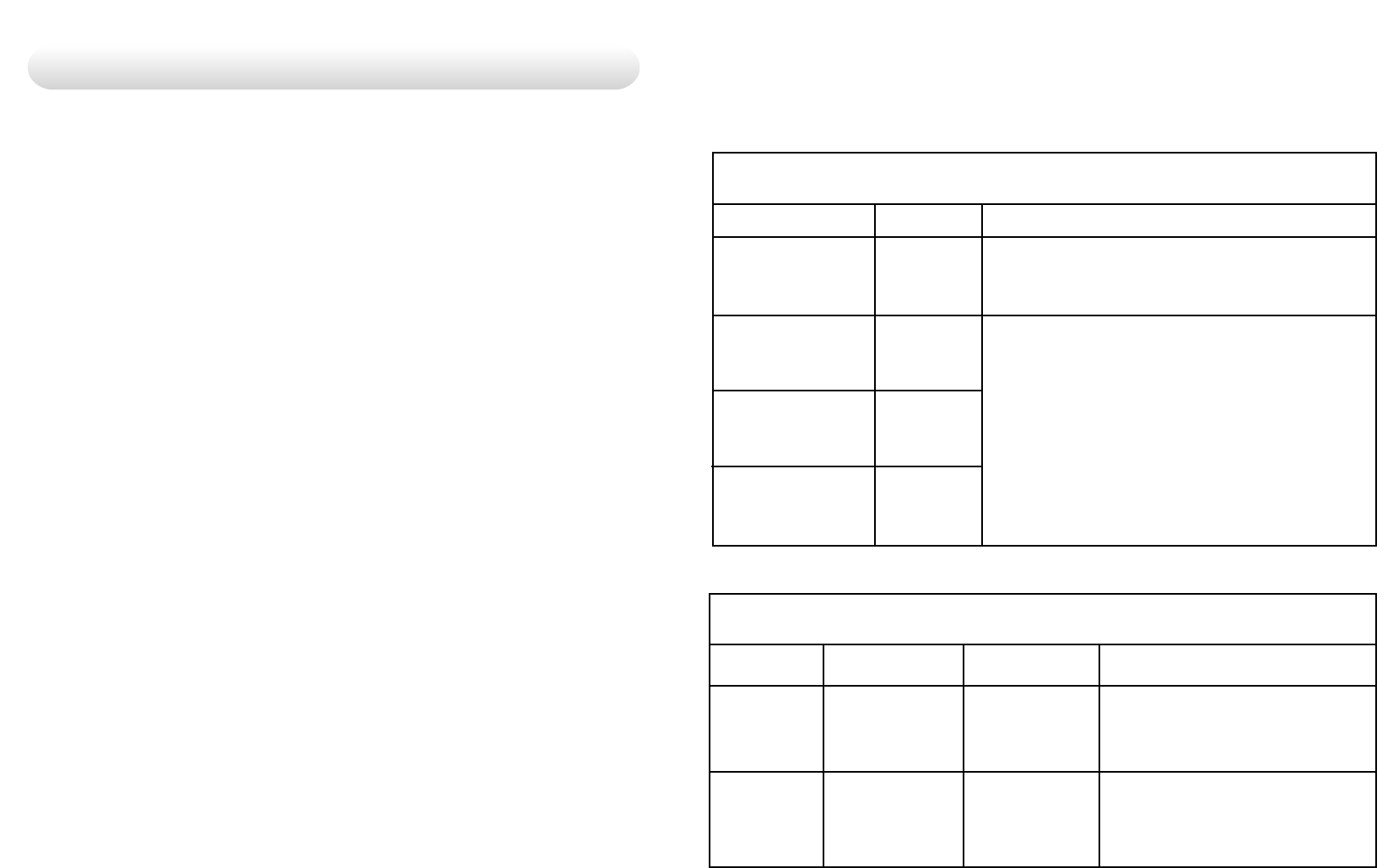
1. Guidance and manufacturer's declaration - electromagnetic emissions
The FS-L4202D is intended for use in the electromagnetic environment specified below.
The customer or the user of the FS-L2401D should assure that it is used in such an environment.
Electromagnetic environment -guidance
The FS-L4202D uses RF energy only for its internal function.
Therefore, its RF emissions are very low and are not likely to
cause any interference in nearby electronic equipment
FS-L4202D is suitable for use in ail establishments, including
domestic establishments and those directly connected to the
public low-voltage power supply network that supplies buildings
used for domestic purposes
2. Guidance and manufacturer's declaration - electromagnetic immunity
FS-L4202D is intended for use in the electromagnetic environment specified below.
The customer or the user of FS-L4202D should assure that it is used in such an environment.
Complince level
6kV Contact
8kV air
2kV for power supply
lines
1kV for input/output
lines
Emission test
RF Emissions
CISPR 11
RF Emissions
CISPR 11
Harmonic emisions
IEC 61000-3-2
Voltage fluctuations
IEC 61000-3-3
Compliance
Group 1
Class B
D
Complies
Immunity test
Electrostatic
discharge(ESD)
IEC61000-4-2
Electrical fast
transient/burst
IEC 61000-4-4
IEC 60601 Test level
6kV Contact
8kV air
2kV for power supply
lines
1kV for input/output
lines
Electromagnetic environment -guidance
Floors should be wood,concrete or
ceramic tile. If floors are covered with
synthetic material, the relative humidity
should be at least 30%
Mains power quality should be that of a
typical commercial or hospital environment.
English - 1110 - English
Surge
IEC 61000-4-5
Conducted RF
IEC 61000-4-6
1kV differential mode
2kV common mode
3 Vrms
150 kHz to 80MHz
1kV differential mode
2kV common mode
3 Vrms
150 kHz to 80MHz
Mains power quality should be that of a
typical commercial or hospital environment.
Portable and mobile RF communications
Portable and mobile RF communications
equipment should be used no closer to any
part of the FS-L4202D, including cables, than
the recommended separation distance
calculated from the equation applicable to
the frequency of the transmitter.
Recommended separation distance
where Pis the maximum output power rating of the transmitter in watts (W)
3. Guidance and manufacturer's declaration - electromagnetic immunity
Immunity test
Radiated RF
IEC 61000-4-3
IEC 60601 Test level
3 V/m
80.0 MHz to 2.5 GHz
Complince level
3 V/m
80.0 MHz to 2.5 GHz
Electromagnetic environment -guidance
Recommended separation distance
where P is the maximum output power rating
of the transmitter in watts (W) according to
the transmitter manufacturer and d is the
recommended separation distance in meters
(m).
Field strengths from fixed RF transmitters, as
deter-mined by an electromagnetic site
survey, a should be less than the compliance
level in each frequency range.
80MHz to 800MHz
80MHz to 2.5GHz
FS-L4202D is intended for use in the electromagnetic environment specified below.
The customer or the user of FS-L4202D should assure that it is used in such an environment.
Immunity test
Power frequency
(50/60Hz)
magnetic field
IEC 61000-4-8
Voltage dips,
short interruptions
and voltage
variations on
power supply
input lines
IEC 61000-4-11
IEC 60601 Test level
3.0A/m
<5 % U
(>95 % dip in U)
for 0.5 cycle
40 % U
(60 % dip in U)
for 5 cycle
70 % U
(30 % dip in U)
for 25 cycle
<5 % U¨‰
(<95 % dip in U¨‰ )
for 5 s
Complince level
3.0A/m
<5 % U
(>95 % dip in U)
for 0.5 cycle
40 % U
(60 % dip in U)
for 5 cycle
70 % U
(30 % dip in U)
for 25 cycle
<5 % U
(<95 % dip in U)
for 5 s
Electromagnetic environment -guidance
Power frequency magnetic fields should be
at levels characteristic of a typical location
in a typical commercial or hospital
environment.
Mains power quaility should
be that of a typical commercial or hospital
environment. If the user of FS-L4202D
requires continued operation during
power mains interruptions, it is
recommended that FS-L4202 be powered
from an uninterruptible power supply or a
battery
NOTE : Uis the A.C. mains voltage prior to application of the test level.
4. Recommended separation distances between portable and mobile
RF communications equipment and the FS-L4202D
- The is intended for use in an electromagnetic environment in which radiated RF
disturbances are controlled. The customer or the user of the FS-L4202D can help
- Prevent electromagnetic interference by maintaining a minimum distance between
portable and mobile
- RF communications equipment (transmitters) and the FS-L4202D as recommended
below,according to the maximum output power of the communications equipment.
150kHz to 80MHz
V1=3Vrms
Rated
maximum output
power of tr
ansmitter [W]
Separation distance according to frequency of transmitter[m]
80MHz to 800MHz
E1=3V/m
800MHz to 2.5GHz
E1=3V/m
English - 1312- English
English - 15
42" LCD Monitor
Parts
User Manual
Accessories
D-SUB Cable S-Video (Y/C) Cable DVI Cable
BNC Cable AC Power code
(Hospital Grade)
14- English
0.116
0.368
1.166
3.687
11.660
0.116
0.3687
1.1660
3.6872
11.6600
0.2333
0.7378
0.2333
0.7375
23.333
0.01
0.1
1
10
100
For transmitters rated at a maximum output power not listed above, the recommended separation distance d
in metres (m)can be estimated using the equation applicable to the frequency of the transmitter, where p is
the maximum output power rating of the transmitter in watts (W) according to the transmitter manufacturer.
NOTE 1) At 80MHz and 800MHz, the separation distance for the higher frequency range applies.
NOTE 2) These guidelines may not apply in all situations. Electromagnetic propagation is affected by
absorption and reflection from structures, objects and people.
Powering On The Unit :
1. Connect the power supply to the display via the power plug.
2. Plug in the DC adapter to AC inlet with power cord cable.
3. Connect the video source to this monitor.
4. Apply power to the peripheral device.
5. Turn on the switch of this monitor.
Quick Startup
English - 1716 - English
600
300
6-M8(USER MUNT HOLE)
Mechanical Product Drawing
AC ON/OFF SWITCH
AC Inlet
OPTICAL IN
DVI IN
DVI OUT
VGA IN
RS232C
SDI IN
SDIOUT
S-VIDEO/Y
S-VIDEO/C
C-VIDEO
RED /Pr
GREEN/Y
BLUE/Pb
C-SYNC/H-SYNC
V-SYNC
Back Panel Jacks
Connector
English - 1918 - English
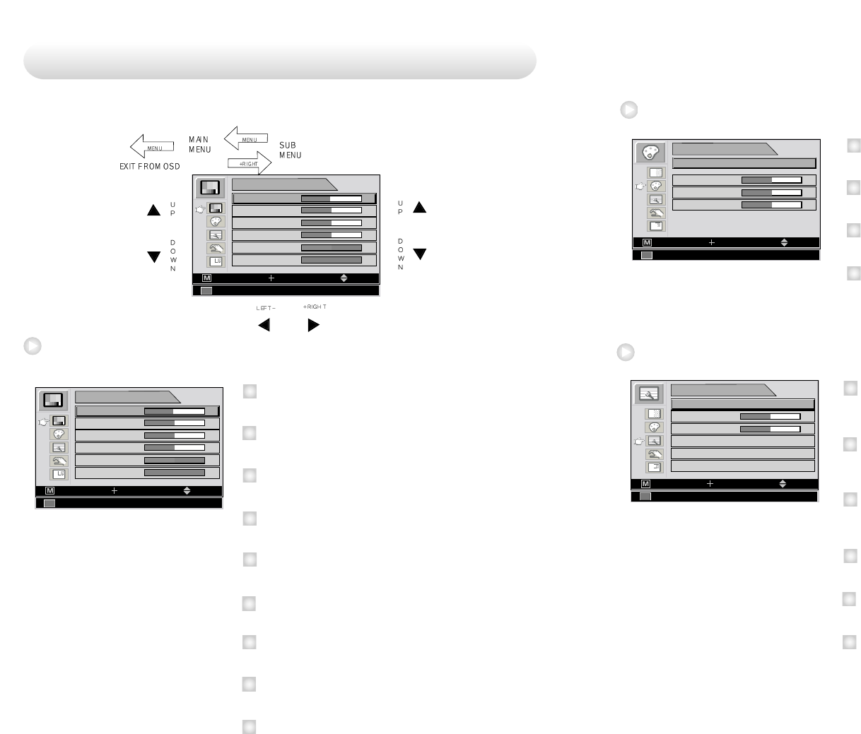
An 8 button keypad, located in button light corner on the front of the
display, allows the user to make adjustments to various display
parameters using the On Screen Display (OSD) system.
Power Indicating LED
Green : Normal mode
Amber: Standby mode
OFF : Monitor off
On-Screen Display (OSD) Function Button
POWER : Turns ON/OFF the monitor.
MENU : With OSD deactivated, Activated to OSD menu.
With OSD activated, Exit from main menu or sub menu.
PIP : With OSD deactivated, Hot key of PIP mode.
UP ( ) : With OSD deactivated, Hot key of the brightness
control and increases the brightness.
With OSD activated, move the cursor upward.
selected function.
DOWN ( ) : With OSD deactivated, Hot key of the brightness
control and decreases the brightness.
With OSD activated, move the cursor downward.
1
2
3
4
5
OSD Button Function
OSD Button Position
Control
English - 2120 - English
This monitor does not adhere to the VESA DPMS standard when no
signal is present on the video inputs.
Status LED sign Power Consumption
Normal Mode Green on <260W
Standby Mode
Amber
Blinking <20W
Power management
- (MINUS) : With OSD deactivated, Hot key of the contrast
control and decreases the contrast.
With OSD activated, decreases the adjustment of
the selected function.
+ (PLUS) : With OSD deactivated, Hot key of the contrast
control and increase the contrast.
With OSD activated, enter sub menu and increases
the adjustment of the selected function.
INPUT : Change the display signal source.
If D-SUB Analog's picture size not matched with full
screen size or image is noisy press the input buttom
during 2~3 seconds then you can see the most
appropriate screen.
6
7
8
English - 2322 - English
50
50
50
COLOR TEMP
MODE USER
RED
GREEN
BLUE
CVIDEO NTSC 60Hz/3.58MHz
MOVESELECTEXIT
Color temp
1
2
3
4
MODE
C
hange the color model. (C1(Redish), C2(greenish). USER)
RED
R
ed balance
(O
nly Working with
USER
mode
) (R
ange
: 0~100)
GREEN
G
reen balance
(O
nly Working with
USER
mode
) (R
ange
: 0~100)
BLUE
B
lue balance
(O
nly Working with
USER
mode
) (R
ange
: 0~100)
50
50
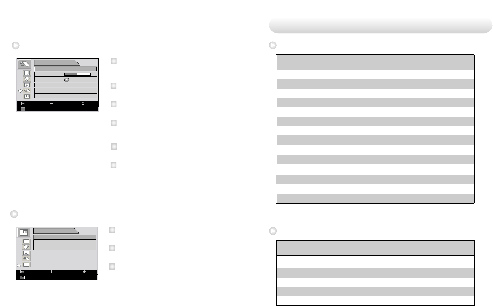
IMAGE
IMAGE SIZE FILL ASPECT
NORMAL
MODE 1
H POSITION
V POSITION
FILTER
0 1 2 3 4 5 6 7 8
OVER SCAN
IMAGE SETTING
CVIDEO NTSC 60Hz/3.58MHz
MOVESELECTEXIT
Image
1
2
3
4
IMAGE SIZE
C
hange the image size (Scaling mode)
(F
ull, Fill aspect, 1:1, Normal, Video, Zoom, video only)
H POSITION
A
djust the horizontal position of the displayed source image.
(R
ange
: 0~100)
V POSITION
A
djust the vertical position of the displayed source image.
(R
ange
: 0~100)
FILTER
S
et the sharpness of image ( Softest, Soft, Normal, Sharp, Sharpest)
OVER SCAN
A
djust the displayed size. (0~8)
IMAGE SETTING
A
llows selection of one of five user defined image presets.
5
6
49
50
50
50
0
ADJUST
BRIGHTNESS
CONTRAST
SHARPNESS
SATURATION
COLOR
EXIT
CVIDEO NTSC 60Hz/3.58MHz
MOVESELECT
BACK LIGHT 100
Adjust
49
50
50
50
0
ADJUST
BRIGHTNESS
CONTRAST
SHARPNESS
SATURATION
COLOR
EXIT
CVIDEO NTSC 60Hz/3.58MHz
MOVESELECT
BACK LIGHT 100
7
8
9
SHARPNESS
A
djust the sharpness of the displayed image.
SATURATION
A
djust the saturation of the image.
COLOR
A
djust the color of the image.
1
2
3
4
BRIGHTNESS
I
ncrease or decrease the brightness.
(R
ange
: 0~100)
CONTRAST
I
ncrease or decrease the Contrast.
(R
ange
: 0~100)
CLOCK
I
ncrease or decrease the sampling frequency.
(R
ange
: 0~100)
PHASE
I
ncrease or decrease the Phase level.
(R
ange
: 0~100)
BACK LIGHT
I
ncrease or decrease the back light dimming level
(R
ange
: 0~100)
AUTO ADJUST
F
it to the most appropriate screen on the D-SUB Analog signal
5
Adjusting OSD
6
English - 2524 - English
PC Supported Mode
SMPTE-274M
SMPTE-296M
SMPTE-260M
SMPTE-125M
ITU-R BT.656
SDI Video format
1080i (60 / 59.94 / 50)
1080p (30 /29.97 / 25 / 24 / 24sF / 23.98 / 23.98sF)
720p (60 / 59.94 / 50)
1035i (60 / 59.94)
480i (59.94)
576i (50)
Standard Signal table
Output Signal Description
640 X 350 @70Hz
720 X 400 @70Hz
640 X 480 @60Hz
640 X 480 @75Hz
800 X 600 @60Hz
800 X 600 @75Hz
1024 X 768 @60Hz
1024 X 768 @75Hz
1152 X 864 @60Hz
1152 X 864 @75Hz
1280 X 1024@75Hz
1360 X 768@75Hz
1600 X 1200@60Hz
1920 X 1080@60Hz
31.469
31.469
31.469
37.500
37.879
46.875
48.363
60.023
54.348
67.500
79.976
47.649
74.077
67.500
70.087
70.082
59.940
75.000
60.317
75.000
60.004
75.029
60.053
75.000
75.025
59.936
59.981
60.000
25.175
28.324
25.175
31.500
40.000
49.500
65.000
78.750
80.000
108.000
135.000
84.625
130.375
148.500
Resolution
Horizontal Frequency
(KHz)
Vertical Frequency
(Hz) Clock Frequency
(MHz)
50
SETUP
LANGUAGE ENGLISH
20 SEC
OSD COLOR
OSD POSITION
DURATION
RESET SETTINGS
AUTO SOURCE SELECT ON
EXIT
CVIDEO NTSC 60Hz/3.58MHz
MOVESELECT
Setup
1
2
3
4
LANGUAGE
C
hange the OSD language (8 language)
(
K
orean
, E
nglish, French, Spanish, German, Chinese, Japanese, Italian)
OSD COLOR
A
djust the OSD background from white opaque to half translucent.
OSD POSITION
C
hange the osd position. (9 Positions)
DURATION
A
djust time until the OSD Menu will disappear after adjusting the menu.
(5, 10, 20, 30, 60, 90, 120, 180, 240 seconds)
RESET SETTINGS
C
hanges the all OSD value to factory out going status.
AUTO SOURCE SELECT
D
isable of enable auto source select.
(ON: Searches through all possible input source untill an active video
source is found.
OFF: Video input is manually selected.)
PIP
LAYOUT PIP
EXIT
CVIDEO
MOVESELECT
SOURCE COMPONENT
SWAP
NTSC 60Hz/3.58MHz
PIP
1
2
3
5
LAYOUT
C
hange the OSD layout. (Single, PIP, PBP1, PBP2)
SOURCE
C
hange the secondary source.
SWAP
S
waps the position and size of the Primary and Secondary image.
6
English - 2726 - English
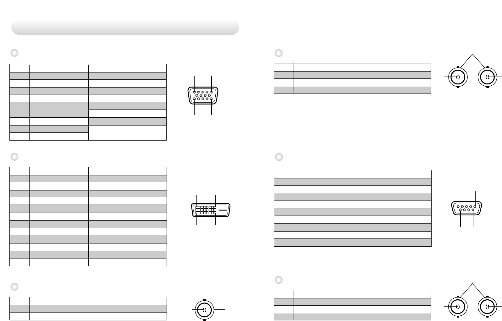
15
69
Pin No. Assignment
1 No Connection
2 TXD
3 RXD
4 No Connection
5 Ground
6 No Connection
7 No Connection
8 No Connection
9 No Connection
RS232C (D-SUB 9Pin)
2
1
Pin No. Assignment
1 S-VIDEO/Y (Luma)
2 S-VIDEO/C (Chroma)
3 Ground
S-Video (BNC)
3
Pin No. Assignment
1 SDI IN
2 SDI OUT
3 Ground
SDI (BNC)
2
1
3
15
11 15
610
Pin No. Assignment Pin No. Assignment
1 Red 9 No Connection
2 Green 10 Ground-Sync
3 Blue 11 Ground
4 Ground 12 DDC Data
5 DDC 5V Standby 13 H.Sync
Cable Connection check 14 V.Sync
6 Ground-Red 15 DDC Clock
7 Ground-Green
8 Ground-Blue
18
17 24
916
2
1
Pin No. Assignment Pin No. Assignment
1 T.M.D.S. Data2- 13 No Connection
2 T.M.D.S. Data2+ 14 +5V Power
3 T.M.D.S. Data2 Shield 15 Cable Connection check
4 No Connection 16 Hot Plug Detect
5 No Connection 17 T.M.D.S. Data0-
6 DDC Clock 18 T.M.D.S. Data0+
7 DDC Data 19 T.M.D.S. Data0 Shield
8 No Connection 20 No Connection
9 T.M.D.S. Data1- 21 No Connection
10 T.M.D.S. Data1+ 22 T.M.D.S. Clock Shield
11 T.M.D.S. Data1 Shield 23 T.M.D.S. Clock+
12 No Connection 24 T.M.D.S. Clock-
Pin No. Assignment
1 Composite
2 Ground
VGA (
15Pin D-Sub)
DVI In,Out (
24Pin DVI-D)
C-Video (BNC)
Signal connector Pin Assignments
English - 2928 - English
Type TFT-LCD
Screen Size 42 linch
Maximum Resolution 1920 X 1080 @ 60Hz
Pixel pitch
0.4845(H) mm X 0.4845(V) mm
Display Colors 16.7M
Contrast Ratio 1000:1
Viewing Angle 89° / 89° / 89° / 89°
Response Time 10msec(Rising+Falling)
Luminance 500cd/m
Horizontal Frequency 30KHz~75KHz
Vertical Frequency 50Hz~75Hz
Maximum 260W
Standby Mode Under 20W
INPUT, -, +,
, , PIP, MENU, POWER
1XDVI, 1XOptical DVI, 1XD-SUB, 1XBNC (CVBS)
Video 2XBNC (SVHS Y/C), 1XBNC (SDI), 5XBNC
(Component Y/G, Pb/B, Pr/R, H/CS, VS Input)
Video 1XDVI, 1XBNC (SDI)
Size and Weight
1024.6 617.4 111.1(
mm
)/ 29Kg
LCD
Panel
Synchro
nization
Model FS-L4202D
Input
Signal
Out
Signal
Power
Consumption
Control key
Front side
Dimension
Specification
Input power AC 100-230V~, 50-60Hz, 3A Max
Assignment
Pin No.
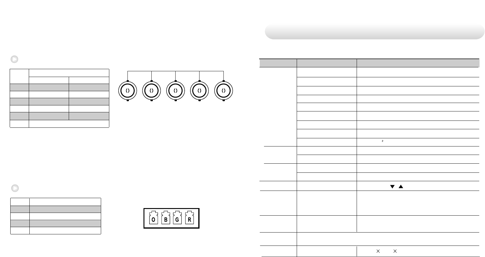
RGBHV/RGBS/YPbPr (BNC)
13
Pin No. Assignment
1 OPICAL Clock
2 OPICAL Blue
3 OPICAL Green
4 OPICAL Red
OPTICAL
24
1 Red Pr
2 Green Y
3 Blue Pb
4 H-Sync / C-Sync No Connection
5 V-Sync No Connection
6 Ground
RGBS Y Pb Pr
R/Pr B/Pb
G/Y CS/HS VS
12345
6