DASAN Network Solutions H640W G-PON ONT User Manual H640W N A QIG EN 131105 V1
DASAN Network Solutions, Inc. G-PON ONT H640W N A QIG EN 131105 V1
UserManual.wiki
>
DASAN Network Solutions
>
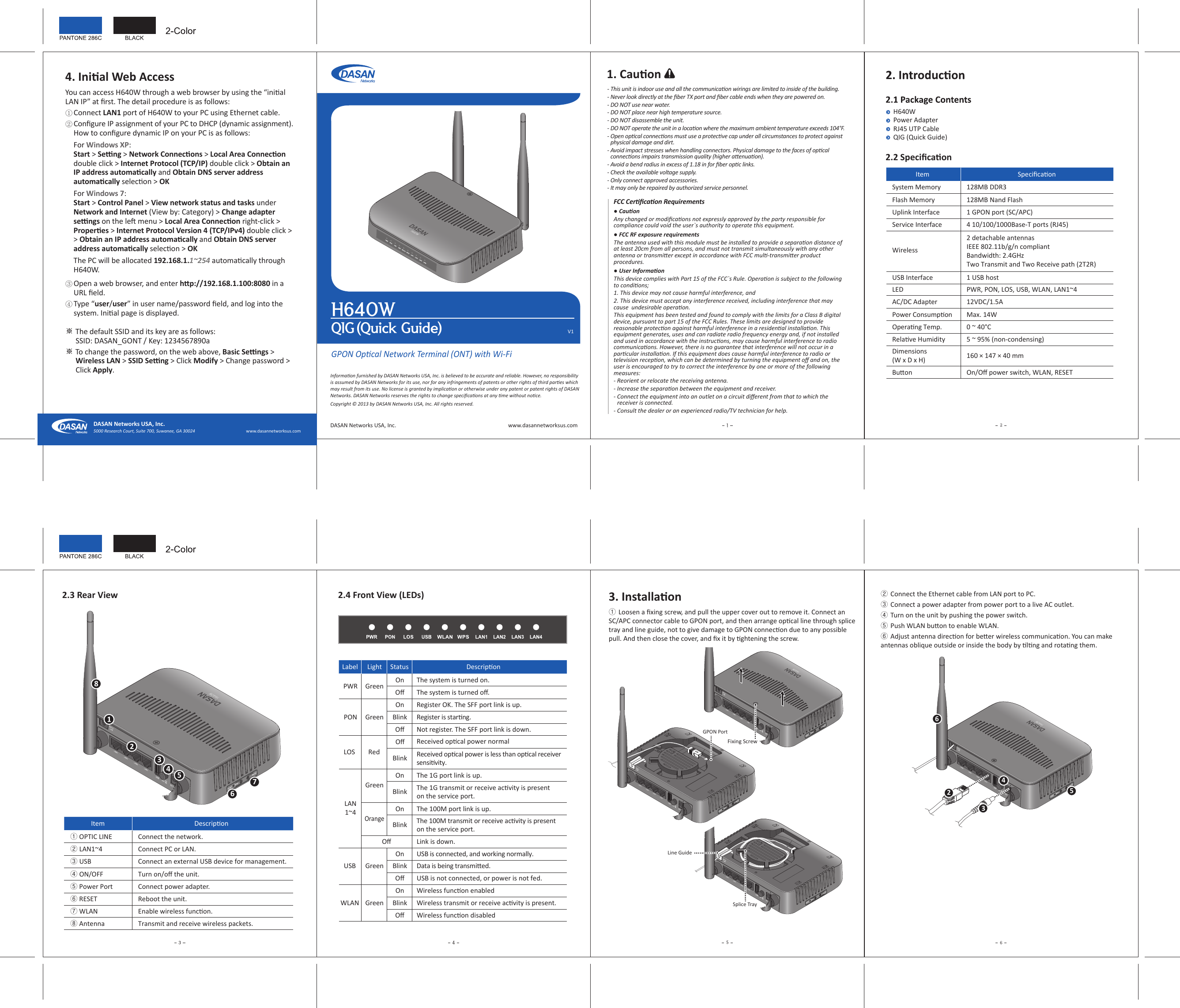
H640W User Manual
User Manual
Navigation menu
Upload a User Manual
Namespaces
Wiki Guide
HTML
PDF
Info
Views
User Manual
Discussion / Help
Navigation