DASAN Network Solutions H640W G-PON ONT User Manual H640W N A QIG EN 131105 V1
DASAN Network Solutions, Inc. G-PON ONT H640W N A QIG EN 131105 V1
User Manual
H640W
Power Adapter
RJ45 UTP Cable
QIG (Quick Guide)
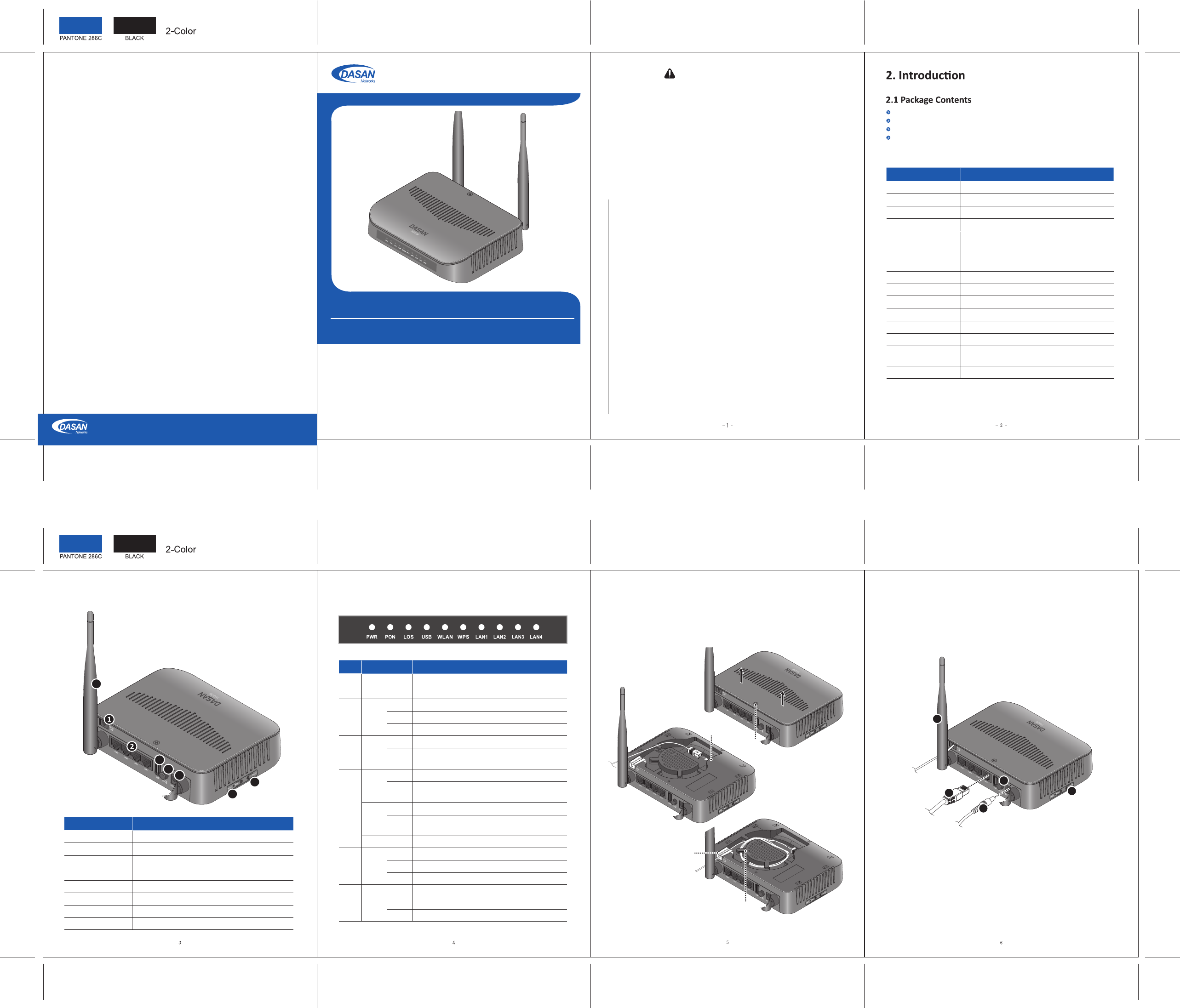
2.3 Rear View ② Connect the Ethernet cable from LAN port to PC.
③ Connect a power adapter from power port to a live AC outlet.
④ Turn on the unit by pushing the power switch.
⑤ Push WLAN buon to enable WLAN.
⑥ Adjust antenna direcon for beer wireless communicaon. You can make
antennas oblique outside or inside the body by lng and rotang them.
① Loosen a fixing screw, and pull the upper cover out to remove it. Connect an
SC/APC connector cable to GPON port, and then arrange opcal line through splice
tray and line guide, not to give damage to GPON connecon due to any possible
pull. And then close the cover, and fix it by ghtening the screw.
3. Installaon
GPON Opcal Network Terminal (ONT) with Wi-Fi
QIG (Quick Guide)
Item Descripon
① OPTIC LINE Connect the network.
② LAN1~4 Connect PC or LAN.
③ USB Connect an external USB device for management.
④ ON/OFF Turn on/off the unit.
⑤ Power Port Connect power adapter.
⑥ RESET Reboot the unit.
⑦ WLAN Enable wireless funcon.
⑧ Antenna Transmit and receive wireless packets.
V1
2.2 Specificaon
Item Specificaon
System Memory 128MB DDR3
Flash Memory 128MB Nand Flash
1 GPON port (SC/APC)
Uplink Interface
Service Interface 4 10/100/1000Base-T ports (RJ45)
USB Interface 1 USB host
Wireless
2 detachable antennas
IEEE 802.11b/g/n compliant
Bandwidth: 2.4GHz
Two Transmit and Two Receive path (2T2R)
LED PWR, PON, LOS, USB, WLAN, LAN1~4
AC/DC Adapter
Operang Temp.
12VDC/1.5A
Power Consumpon Max. 14W
0 ~ 40°C
Relave Humidity 5 ~ 95% (non-condensing)
Dimensions
(W x D x H) 160 × 147 × 40 mm
Buon On/Off power switch, WLAN, RESET
Label Light Status Descripon
PWR Green On
Off The system is turned off.
The system is turned on.
Received opcal power normal
Received opcal power is less than opcal receiver
sensivity.
PON Green
On Register OK. The SFF port link is up.
Blink Register is starng.
Off Not register. The SFF port link is down.
LOS Red
Off
Blink
Off Link is down.
LAN
1~4
Green
On The 1G port link is up.
Blink on the service port.
Orange
On The 100M port link is up.
Blink on the service port.
The 1G transmit or receive acvity is present
The 100M transmit or receive acvity is present
USB Green
On USB is connected, and working normally.
Blink Data is being transmied.
Off USB is not connected, or power is not fed.
WLAN Green
On Wireless funcon enabled
Blink Wireless transmit or receive acvity is present.
Off Wireless funcon disabled
2.4 Front View (LEDs)
GPON Port
4. Inial Web Access
You can access H640W through a web browser by using the “inial
LAN IP” at first. The detail procedure is as follows:
① Connect LAN1 port of H640W to your PC using Ethernet cable.
② Configure IP assignment of your PC to DHCP (dynamic assignment).
How to configure dynamic IP on your PC is as follows:
For Windows XP:
Start > Seng > Network Connecons > Local Area Connecon
double click > Internet Protocol (TCP/IP) double click > Obtain an
IP address automacally and Obtain DNS server address
automacally selecon > OK
For Windows 7:
Start > Control Panel > View network status and tasks under
Network and Internet (View by: Category) > Change adapter
sengs on the le menu > Local Area Connecon right-click >
Properes > Internet Protocol Version 4 (TCP/IPv4) double click >
> Obtain an IP address automacally and Obtain DNS server
address automacally selecon > OK
The PC will be allocated 192.168.1.1~254 automacally through
H640W.
③ Open a web browser, and enter hp://192.168.1.100:8080 in a
URL field.
④ Type “user/user” in user name/password field, and log into the
system. Inial page is displayed.
※ The default SSID and its key are as follows:
SSID: DASAN_GONT / Key: 1234567890a
※ To change the password, on the web above, Basic Sengs >
Wireless LAN > SSID Seng > Click Modify > Change password >
Click Apply.
3
4
5
6
7
8
Fixing Screw
Splice Tray
Line Guide
3
4
5
6
2
1. Cauon
- This unit is indoor use and all the communicaon wirings are limited to inside of the building.
- Never look directly at the fiber TX port and fiber cable ends when they are powered on.
- DO NOT use near water.
- DO NOT place near high temperature source.
- DO NOT disassemble the unit.
- DO NOT operate the unit in a locaon where the maximum ambient temperature exceeds 104°F.
- Open opcal connecons must use a protecve cap under all circumstances to protect against
physical damage and dirt.
- Avoid impact stresses when handling connectors. Physical damage to the faces of opcal
connecons impairs transmission quality (higher aenuaon).
- Avoid a bend radius in excess of 1.18 in for fiber opc links.
- Check the available voltage supply.
- Only connect approved accessories.
- It may only be repaired by authorized service personnel.
FCC Cerficaon Requirements
● Cauon
Any changed or modificaons not expressly approved by the party responsible for
compliance could void the user`s authority to operate this equipment.
● FCC RF exposure requirements
The antenna used with this module must be installed to provide a separaon distance of
at least 20cm from all persons, and must not transmit simultaneously with any other
antenna or transmier except in accordance with FCC mul-transmier product
procedures.
● User Informaon
This device complies with Part 15 of the FCC`s Rule. Operaon is subject to the following
to condions;
1. This device may not cause harmful interference, and
2. This device must accept any interference received, including interference that may
cause undesirable operaon.
This equipment has been tested and found to comply with the limits for a Class B digital
device, pursuant to part 15 of the FCC Rules. These limits are designed to provide
reasonable protecon against harmful interference in a residenal installaon. This
equipment generates, uses and can radiate radio frequency energy and, if not installed
and used in accordance with the instrucons, may cause harmful interference to radio
communicaons. However, there is no guarantee that interference will not occur in a
parcular installaon. If this equipment does cause harmful interference to radio or
television recepon, which can be determined by turning the equipment off and on, the
user is encouraged to try to correct the interference by one or more of the following
measures:
- Reorient or relocate the receiving antenna.
- Increase the separaon between the equipment and receiver.
- Connect the equipment into an outlet on a circuit different from that to which the
receiver is connected.
- Consult the dealer or an experienced radio/TV technician for help.
5000 Research Court, Suite 700, Suwanee, GA 30024 www.dasannetworksus.com
DASAN Networks USA, Inc.
Informaon furnished by DASAN Networks USA, Inc. is believed to be accurate and reliable. However, no responsibility
is assumed by DASAN Networks for its use, nor for any infringements of patents or other rights of third pares which
may result from its use. No license is granted by implicaon or otherwise under any patent or patent rights of DASAN
Networks. DASAN Networks reserves the rights to change specificaons at any me without noce.
Copyright © 2013 by DASAN Networks USA, Inc. All rights reserved.
DASAN Networks USA, Inc. www.dasannetworksus.com