DJI Innovations Technology P330 Phantom R/C Controller User Manual Manual 1 of 2
DJI Innovations Technology Co., Ltd. Phantom R/C Controller Manual 1 of 2
Contents
- 1. Manual 1 of 2
- 2. Manual 2 of 2
Manual 1 of 2
©2012 大疆创新 版权所有 1 |
PHANTOM QuickStartManual
Introduction
The PHANTOM is an all-in-one small Quad Copter designed for multi-rotor enthusiasts. Before shipping from the
factory, it has been configured and fully tested, which means you have no set-up or configuration to do.
Built-in autopilot system
Built-in R/C receiver
High intensity LED lights
Manual/ATTI./GPS ATTI. modes
Intelligent Orientation Control Mode
Low Voltage Protection
Enhanced Fail Safe
Frame for mounting a Camera (GoPro)
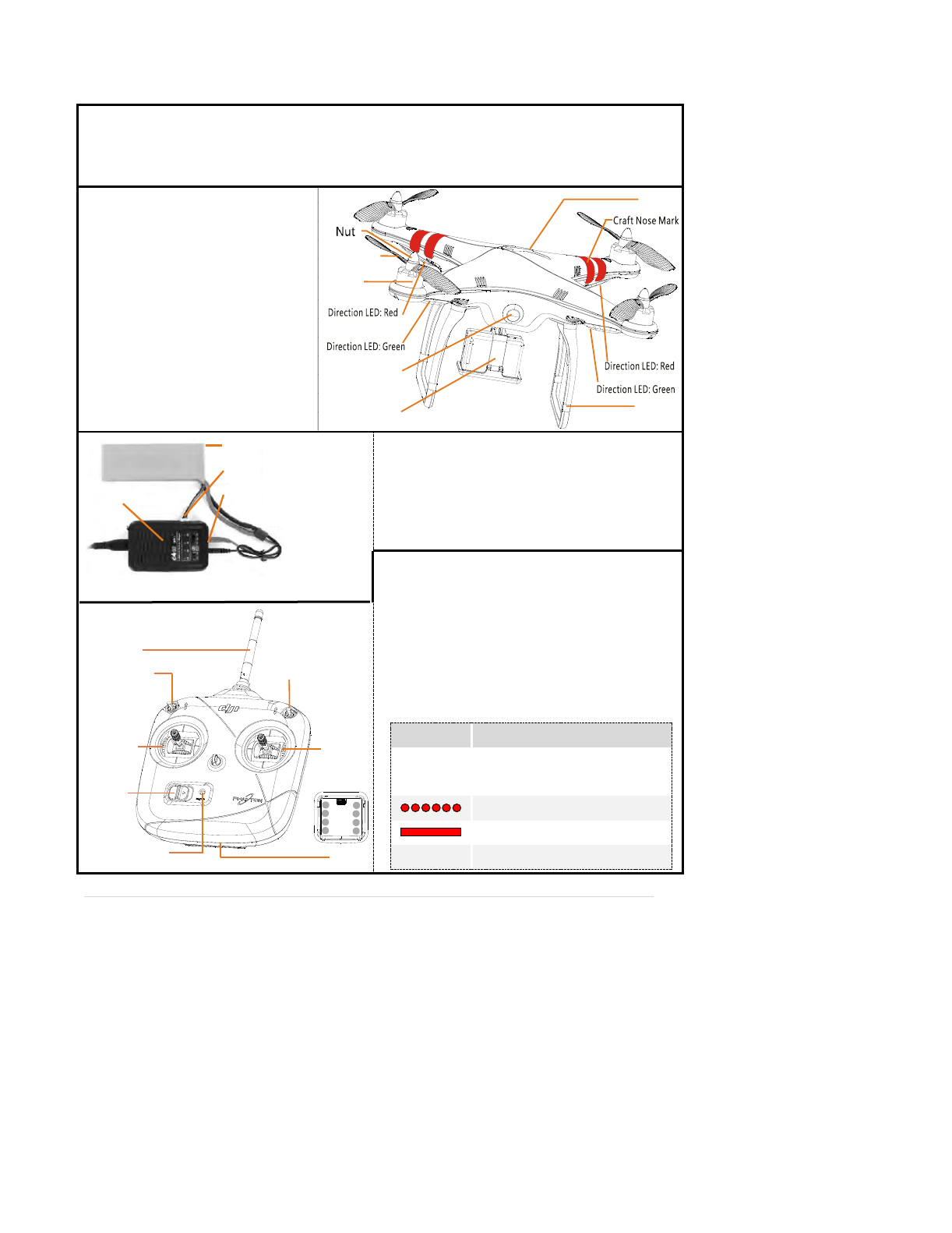
Propeller
LED Indicator
Cover
Battery
CameraM F
ounting rame
Bi-pod
Motor
Aircraft
IOC Switch
Power
LED Indicator
Antenna
ModeControlSiwtch
Battery
Joystick
-
+
+
-+
--
-+
-
Joystick
TX
ACInput: 100-240V
Battery Type: LiPo
Cell Count: 2-4 cells
Current Drain for Balancing: 200mA
Working Frequency:2.4GHz
Control Channel Numbers of TX:
Communication Distance:300m
Receiver Sensitivity(1%PER):>-93dBm
Power Consumption ofTX:<20dBm
Working Current /Voltage:52 mA@6V
AA Battery:4 Required
Indicator Function
B--------BB
The throttle stick isn’t in the lowest
position after turning on.
Linking between the TX and the RX
Normal Operation
BB………… Low-battery Alarm
Battery
BatterySocket
Cell 3
Charger
Charger
©2012 大疆创新 版权所有 2 |
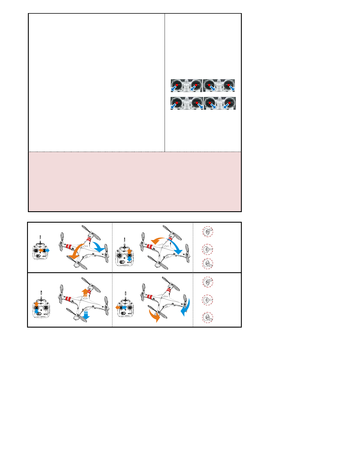
Flight Test
1) Make sure the LiPo battery is fully charged.
2) Lower the throttle stick to the bottom position, and turn on the TX.
3) After you have turned on the TX for 2sec, install the battery and connect
it to the battery connector of the multi rotor to power on the PHANTOM.
4) Tx and Rx should now be linking. The LED indicator on the TX will
change to blinking red (about 1 sec). When the linking is successful, the LED
indicator on the TX will change to solid red.
5) Turn the Tx IOC mode to OFF. Switch the mode control switch on the Tx
to make sure it works properly, refer to the LED indicator on the multi rotor.
6) Execute the CSC Command (see right) and raise the throttle stick slowly.
Make sure the ESC’s work properly and the rotation direction of the motors is
the same as the marks. The direction LED lights indicate: nose is red and the
tail is green, they will turn off if the motors stop.
7) Ready to fly.
8) Switch the Tx control mode switch to ATTI. Mode and then lightly move
the Tx sticks in Roll, Pitch and Yaw to feel if the aircraft moves in the
corresponding direction.
9) Take off the multi rotor in ATTI. Mode.
10) Finish and land the multi rotor.
Start and Stop Motors: You have to
execute any one of the following four
Combination Stick Commands (CSC)
Note:In Atti /GPS Atti. Mode, any one of
the following will stop the motors: Not
raising the throttle stick within 3 seconds
after the motors start. Throttle stick under
10%, and after landing for 3 seconds. The
angle of the multi-rotor is over 70°, and
throttle stick under 10%.
ESC (motor controller) State
Ready: ♪1234567
Throttle stick is not at bottom: BBBBBB…
Input signal abnormal: B--------B…
Input voltage abnormal:BB---BB…
Note:
Please always switch on the transmitter first, then power on the quad-rotor before takeoff! Power off the quad-rotor first, and
then switch off the transmitter after landing!
After powering on and before the motors start, if the multi rotor LED double blinks yellow without Tx stick movement, you should
power cycle the multi rotor.
If the multi rotor LED flashes quickly Red then this indicates battery voltage is low, please land ASAP.
The multi rotor will automatically hover (or return home if in GPS mode) if the fail safe mode is active.
We recommend that you take off the multi rotor in ATTI. Mode. Manual mode is very sensitive.
Transmitter Control Description
Roll Pitch
M
O
D
E
GPS ATTI.
ATTI.
Manual
Throttle
Yaw
I
O
C
OFF
Orientation
Locked
HomePoint
Locked
©2012 大疆创新 版权所有 3 |
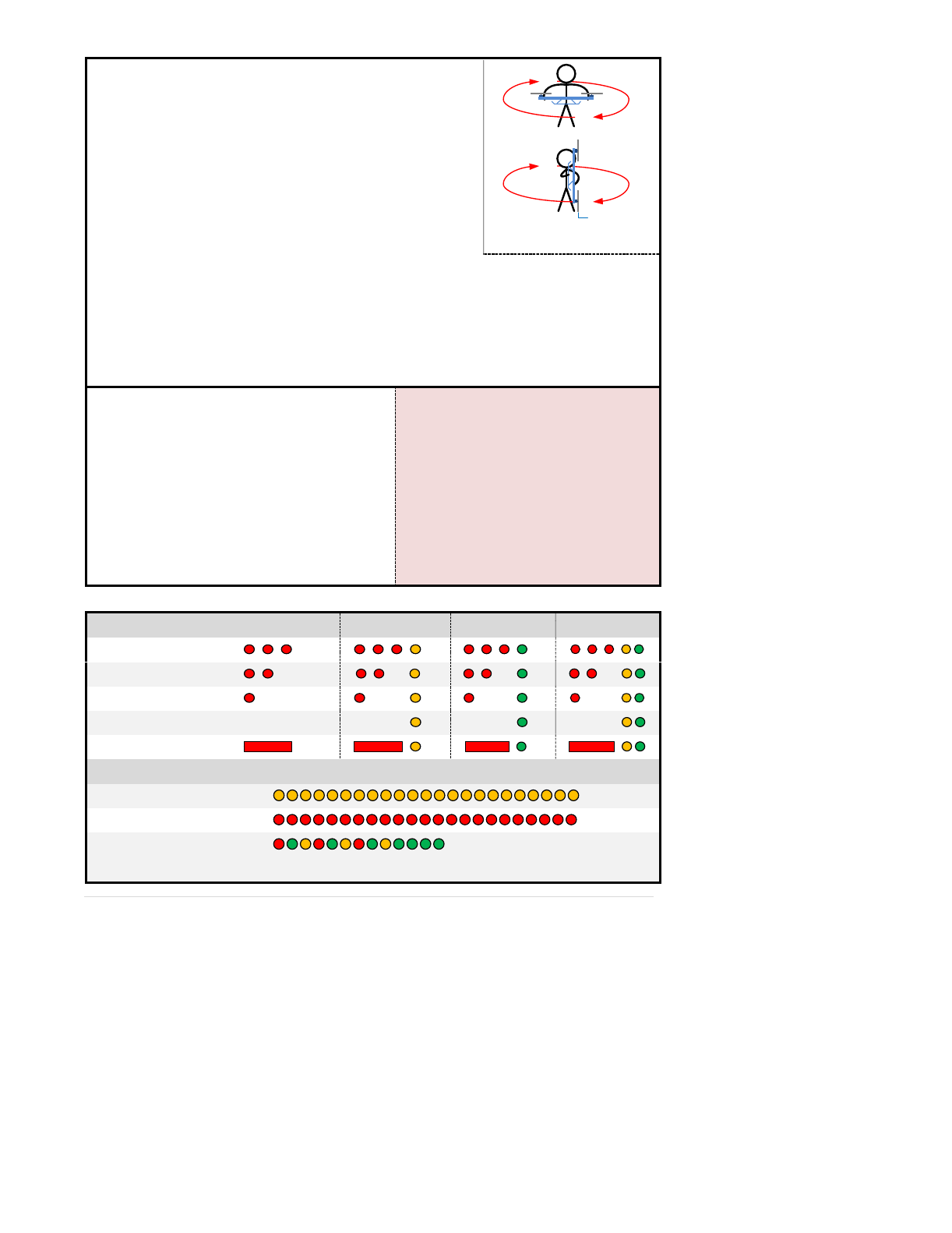
GPS Flight Test
Carry out the compass calibration
1) Enter calibration mode: quickly switch the control mode switch from
Manual Mode to GPS Atti. Mode for 6 to 10 times, The LED indicator will
turn on constantly yellow.
2) Rotate your multi rotor around the horizontal axis until the LED
changes to constant green, then go to the next step
3) Hold your multi rotor vertically and rotate it around its vertical axis,
keep rotating until the LED turns off, meaning the calibration is finished.
Aircraft Nose
4) The LED indicator will show whether the calibration was successful or not.
If the calibration was successful, calibration mode will exit automatically.
If the LED keeps flashing quickly Red, the calibration has failed. Switch the control mode switch one
time to cancel the current calibration, and then re-start from step 1.
If you keep having calibration failure, it might suggest that there is very strong magnetic interference around
the GPS & Compass module, please avoid flying in this area.
Flight Procedure
1) Switch to GPS ATTI. Mode.
2) The LED flashing Red indicates that the
PHANTOM is still acquiring GPS satellite signals, wait
until the red LED is off, meaning the PHANTOM has
found more than 7 GPS satellites.
3) Switch the system to ATTI. Mode and take off.
4) Hover and switch to GPS ATTI. Mode.
5) Finish and land the multi rotor.
Note:
After powering on and before the motors start, if the
LED double flashes Green without Tx stick movement,
you should power cycle the multi rotor.
In GPS mode the multi rotor will go home if the fail safe
mode is active.
If the LED lights Red, please hover the aircraft until it
turns off, so as to have better flight performance.
Multi Rotor LED Indicator
Control Mode LED
Manual
Atti.
GPS Atti.
IOC
GPS satellites < 5
GPS satellites = 5
GPS satellites = 6
GPS satellites >6
None
Attitude status bad
Others
Tx signal lost
Low voltage / Other errors
System start and self-check
Do NOT move any command sticks during power up! Please contact us if the last four green blinks are abnormal.