Danfoss A S TYPE-CFR Wireless Floor Heating Control System User Manual Vi 88 M1 03

Danfoss A/S Wireless Floor Heating Control System Vi 88 M1 03

Contents

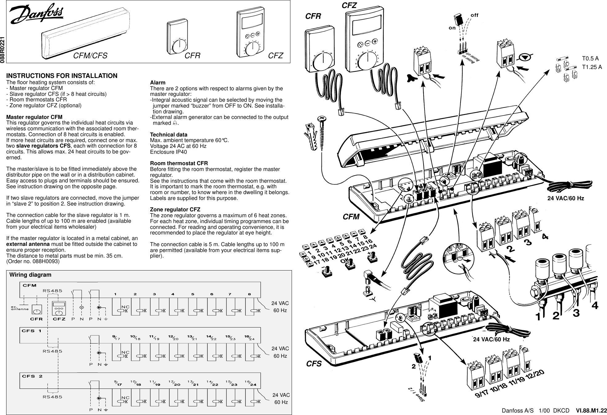
Installation Instructions

CFZCFR                 CFMCFST0.5 AT1.25 ACFM/CFS  CFR       CFZWiring diagramDanfoss A/S   1/00  DKCD    VI.88.M1.22088R0221INSTRUCTIONS FOR INSTALLATIONThe floor heating system consists of:- Master regulator CFM- Slave regulator CFS (if > 8 heat circuits)- Room thermostats CFR- Zone regulator CFZ (optional)Master regulator CFMThis regulator governs the individual heat circuits viawireless communication with the associated room ther-mostats. Connection of 8 heat circuits is enabled.If more heat circuits are required, connect one or max.two slave regulators CFS, each with connection for 8circuits. This allows max. 24 heat circuits to be gov-erned.The master/slave is to be fitted immediately above thedistributor pipe on the wall or in a distribution cabinet.Easy access to plugs and terminals should be ensured.See instruction drawing on the opposite page.If two slave regulators are connected, move the jumperin “slave 2” to position 2. See instruction drawing.The connection cable for the slave regulator is 1 m.Cable lengths of up to 100 m are enabled (availablefrom your electrical items wholesaler)If the master regulator is located in a metal cabinet, anexternal antenna must be fitted outside the cabinet toensure proper reception.The distance to metal parts must be min. 35 cm.(Order no. 088H0093)AlarmThere are 2 options with respect to alarms given by themaster regulator:-Integral acoustic signal can be selected by moving thejumper marked “buzzer” from OFF to ON. See installa-tion drawing.-External alarm generator can be connected to the outputmarked %.Technical dataMax. ambient temperature 60°C.Voltage 24 AC at 60 HzEnclosure IP40Room thermostat CFRBefore fitting the room thermostat, register the masterregulator.See the instructions that come with the room thermostat.It is important to mark the room thermostat, e.g. withroom or number, to know where in the dwelling it belongs.Labels are supplied for this purpose.Zone regulator CFZThe zone regulator governs a maximum of 6 heat zones.For each heat zone, individual timing programmes can beconnected. For reading and operating convenience, it isrecommended to place the regulator at eye height.The connection cable is 5 m. Cable lengths up to 100 mare permitted (available from your electrical items sup-plier).230 VAC:T0.5 A+F4 A24 VAC/60 Hz24 VAC60 Hz24 VAC60 Hz24 VAC60 Hz24 VAC/60 Hz
Putting into operationLED for master regulator  LED for slave regulator 1      LED for slave regulator 2Fig.1Fig. 2Vertical and horizontal LEDsshow the operating mode of theoutputs in combination.Light: heat is added to theroom.No light: no heat is added to theroomExample: When the 4th hori-zontal LED and the 1st verti-cal LED are lit, heat is sup-plied to room 4.LED row for outputsRegistration of room thermostat withoutput(s)-Connect the room thermostat (fig. 1) and theCFM master regulator via the black installa-tion cable. The first vacant output in the reg-istration field will flash. Other vacant outputswill be lit. Outputs already registered are noton (fig. 2).-If OK is pressed briefly, the room thermo-stat has been registered with the output andthe LED goes off (fig. 2).If the room thermostat is to be registeredwith more than one output, go to these out-puts by means of the +/- keys and confirmby pressing OK briefly.When the installation cable is removed, thered LED underneath the battery cover (fig.1) will flash for at least one minute (Testmode).Unregistration of room thermostatThe room thermostat and the master regula-tor may not be connected.-Press OK for 5 sec..; the first LED in the rowfor registered room thermostat will flash (fig.2). Other LEDs for registered room thermo-stats will flash.-Use the +/- keys to go to the room thermo-stat to be unregistered (it will flash).-Confirm unregistration by pressing OK for 5sec.. The LED goes off.Test of room thermostatIf a defect in a room thermostat is sus-pected, the following test may be carried out:-Set the thermostat to the highest tempera-ture (EC).-Move the function switch o the side of theroom thermostat to a new position.-If the LED underneath the battery cover (fig.1) flashes quickly for at least one minute,the room thermostat is in order.Transmission intervalA room thermostat transmits regularly. Whena signal is received from the master regula-tor, two quick flashes are sent. Subse-quently, the normal operating mode is dis-played.OperationDuring normal operation, the status of themaster regulator outputs is shown.If the status of the outputs of the slave regu-lators is to be shown, scroll by means of the+/- keys. After approx. 10 sec. the systemreverts to the output status of the masterregulator.Acoustic alarm is disconnected by pressing +/- or pressing OK in the registration field.Trouble shootingRegistration field shows(Zone regulator shows)Operating disturbances   are shown as:Mode Cause of error OutputsLED for master/slave regulatorflashes and LED for outputflashes.(Alarm symbol in zone regulatorflashes)There has been no connection theroom thermostat for more than 90min.- Defective battery in room  thermostat- Defective room thermostat- Too long transmission distance toroom thermostat- Present room temperature is be-low 4°CLED for slave regulator and allroom thermostats flashes.(Alarm symbol in zone regulatorflashes)No connection to slave regulator - Bus cable defective or  discon-nected.- Slave regulator defective.- Two slave regulators are installedas “slave 1” and “slave 2”.No connection to zone regulator - Bus cable defective or  disconnected.- Zone regulator defective.(No display in zone regulatordisplay)Master regulator does not react(Display shows “Connectionbroken”) - Defective fuse- Defective circuitFrost protection:Output 15 min. open;45 min. closed.Frostdanger Present output is open.- Acoustic alarm in master regulator (if activated)- Flashes in the registration field of the master regulator- Alarm symbol in the zone regulator display (if used)Warning:  Changes or modifications to this unit not ex-pressly approved by the party responsible for compliancecould void the user’s authority to operate the equipment.“This device complies with RSS-210 of Industry Canada.Operation is subject to the following two conditions: (1) thisdevice may not cause interference, and (2) this device mustaccept any interference, including interference that maycause undesired operation of the device.”FCC ID:  XXXTYPE.CFRThis device complies with Part 15 of the FCC Rules.Operation is subject to the following two conditions:(1) This device may not cause harmful interference, and(2) This device must accept any interference received,including interference that may cause undesired operation.

Navigation menu