Danfoss A S TYPE-CFR Wireless Floor Heating Control System User Manual Vi 88 M1 03
Danfoss A/S Wireless Floor Heating Control System Vi 88 M1 03
Contents
- 1. Users Guide
- 2. Installation Instructions
Installation Instructions
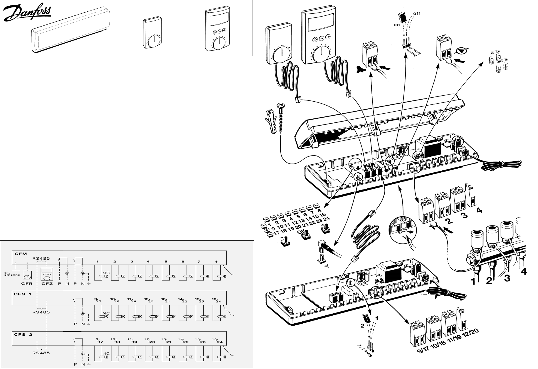
CFZ
CFR
CFM
CFS
T0.5 A
T1.25 A
CFM/CFS CFR CFZ
Wiring diagram
Danfoss A/S 1/00 DKCD VI.88.M1.22
088R0221
INSTRUCTIONS FOR INSTALLATION
The floor heating system consists of:
- Master regulator CFM
- Slave regulator CFS (if > 8 heat circuits)
- Room thermostats CFR
- Zone regulator CFZ (optional)
Master regulator CFM
This regulator governs the individual heat circuits via
wireless communication with the associated room ther-
mostats. Connection of 8 heat circuits is enabled.
If more heat circuits are required, connect one or max.
two slave regulators CFS, each with connection for 8
circuits. This allows max. 24 heat circuits to be gov-
erned.
The master/slave is to be fitted immediately above the
distributor pipe on the wall or in a distribution cabinet.
Easy access to plugs and terminals should be ensured.
See instruction drawing on the opposite page.
If two slave regulators are connected, move the jumper
in “slave 2” to position 2. See instruction drawing.
The connection cable for the slave regulator is 1 m.
Cable lengths of up to 100 m are enabled (available
from your electrical items wholesaler)
If the master regulator is located in a metal cabinet, an
external antenna must be fitted outside the cabinet to
ensure proper reception.
The distance to metal parts must be min. 35 cm.
(Order no. 088H0093)
Alarm
There are 2 options with respect to alarms given by the
master regulator:
-Integral acoustic signal can be selected by moving the
jumper marked “buzzer” from OFF to ON. See installa-
tion drawing.
-External alarm generator can be connected to the output
marked %.
Technical data
Max. ambient temperature 60°C.
Voltage 24 AC at 60 Hz
Enclosure IP40
Room thermostat CFR
Before fitting the room thermostat, register the master
regulator.
See the instructions that come with the room thermostat.
It is important to mark the room thermostat, e.g. with
room or number, to know where in the dwelling it belongs.
Labels are supplied for this purpose.
Zone regulator CFZ
The zone regulator governs a maximum of 6 heat zones.
For each heat zone, individual timing programmes can be
connected. For reading and operating convenience, it is
recommended to place the regulator at eye height.
The connection cable is 5 m. Cable lengths up to 100 m
are permitted (available from your electrical items sup-
plier).
230 VAC:
T0.5 A+F4 A
24 VAC/60 Hz
24 VAC
60 Hz
24 VAC
60 Hz
24 VAC
60 Hz
24 VAC/60 Hz
Putting into operation
LED for master regulator
LED for slave regulator 1
LED for slave regulator 2
Fig.1
Fig. 2
Vertical and horizontal LEDs
show the operating mode of the
outputs in combination.
Light: heat is added to the
room.
No light: no heat is added to the
room
Example: When the 4th hori-
zontal LED and the 1st verti-
cal LED are lit, heat is sup-
plied to room 4.
LED row for outputs
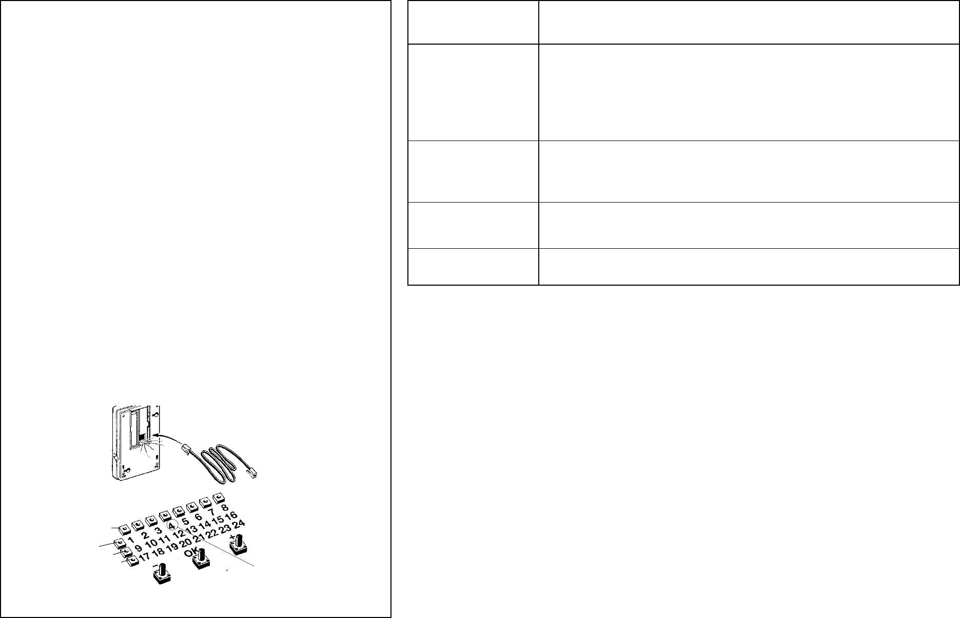
Registration of room thermostat with
output(s)
-Connect the room thermostat (fig. 1) and the
CFM master regulator via the black installa-
tion cable. The first vacant output in the reg-
istration field will flash. Other vacant outputs
will be lit. Outputs already registered are not
on (fig. 2).
-If OK is pressed briefly, the room thermo-
stat has been registered with the output and
the LED goes off (fig. 2).
If the room thermostat is to be registered
with more than one output, go to these out-
puts by means of the +/- keys and confirm
by pressing OK briefly.
When the installation cable is removed, the
red LED underneath the battery cover (fig.
1) will flash for at least one minute (Test
mode).
Unregistration of room thermostat
The room thermostat and the master regula-
tor may not be connected.
-Press OK for 5 sec..; the first LED in the row
for registered room thermostat will flash (fig.
2). Other LEDs for registered room thermo-
stats will flash.
-Use the +/- keys to go to the room thermo-
stat to be unregistered (it will flash).
-Confirm unregistration by pressing OK for 5
sec.. The LED goes off.
Test of room thermostat
If a defect in a room thermostat is sus-
pected, the following test may be carried out:
-Set the thermostat to the highest tempera-
ture (EC).
-Move the function switch o the side of the
room thermostat to a new position.
-If the LED underneath the battery cover (fig.
1) flashes quickly for at least one minute,
the room thermostat is in order.
Transmission interval
A room thermostat transmits regularly. When
a signal is received from the master regula-
tor, two quick flashes are sent. Subse-
quently, the normal operating mode is dis-
played.
Operation
During normal operation, the status of the
master regulator outputs is shown.
If the status of the outputs of the slave regu-
lators is to be shown, scroll by means of the
+/- keys. After approx. 10 sec. the system
reverts to the output status of the master
regulator.
Acoustic alarm is disconnected by pressing +/- or pressing OK in the registration field.
Trouble shooting
Registration field shows
(Zone regulator shows)
Operating disturbances are shown as:
Mode Cause of error Outputs
LED for master/slave regulator
flashes and LED for output
flashes.
(Alarm symbol in zone regulator
flashes)
There has been no connection the
room thermostat for more than 90
min.
- Defective battery in room
thermostat
- Defective room thermostat
- Too long transmission distance to
room thermostat
- Present room temperature is be-
low 4°C
LED for slave regulator and all
room thermostats flashes.
(Alarm symbol in zone regulator
flashes)
No connection to slave regulator - Bus cable defective or discon-
nected.
- Slave regulator defective.
- Two slave regulators are installed
as “slave 1” and “slave 2”.
No connection to zone regulator - Bus cable defective or
disconnected.
- Zone regulator defective.
(No display in zone regulator
display)
Master regulator does not react
(Display shows “Connection
broken”) - Defective fuse
- Defective circuit
Frost protection:
Output 15 min. open;
45 min. closed.
Frostdanger Present output is open.
- Acoustic alarm in master regulator (if activated)
- Flashes in the registration field of the master regulator
- Alarm symbol in the zone regulator display (if used)
Warning: Changes or modifications to this unit not ex-
pressly approved by the party responsible for compliance
could void the user’s authority to operate the equipment.
“This device complies with RSS-210 of Industry Canada.
Operation is subject to the following two conditions: (1) this
device may not cause interference, and (2) this device must
accept any interference, including interference that may
cause undesired operation of the device.”
FCC ID: XXXTYPE.CFR
This device complies with Part 15 of the FCC Rules.
Operation is subject to the following two conditions:
(1) This device may not cause harmful interference, and
(2) This device must accept any interference received,
including interference that may cause undesired operation.