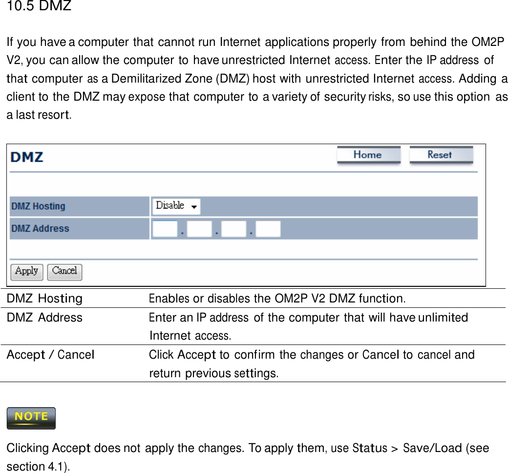
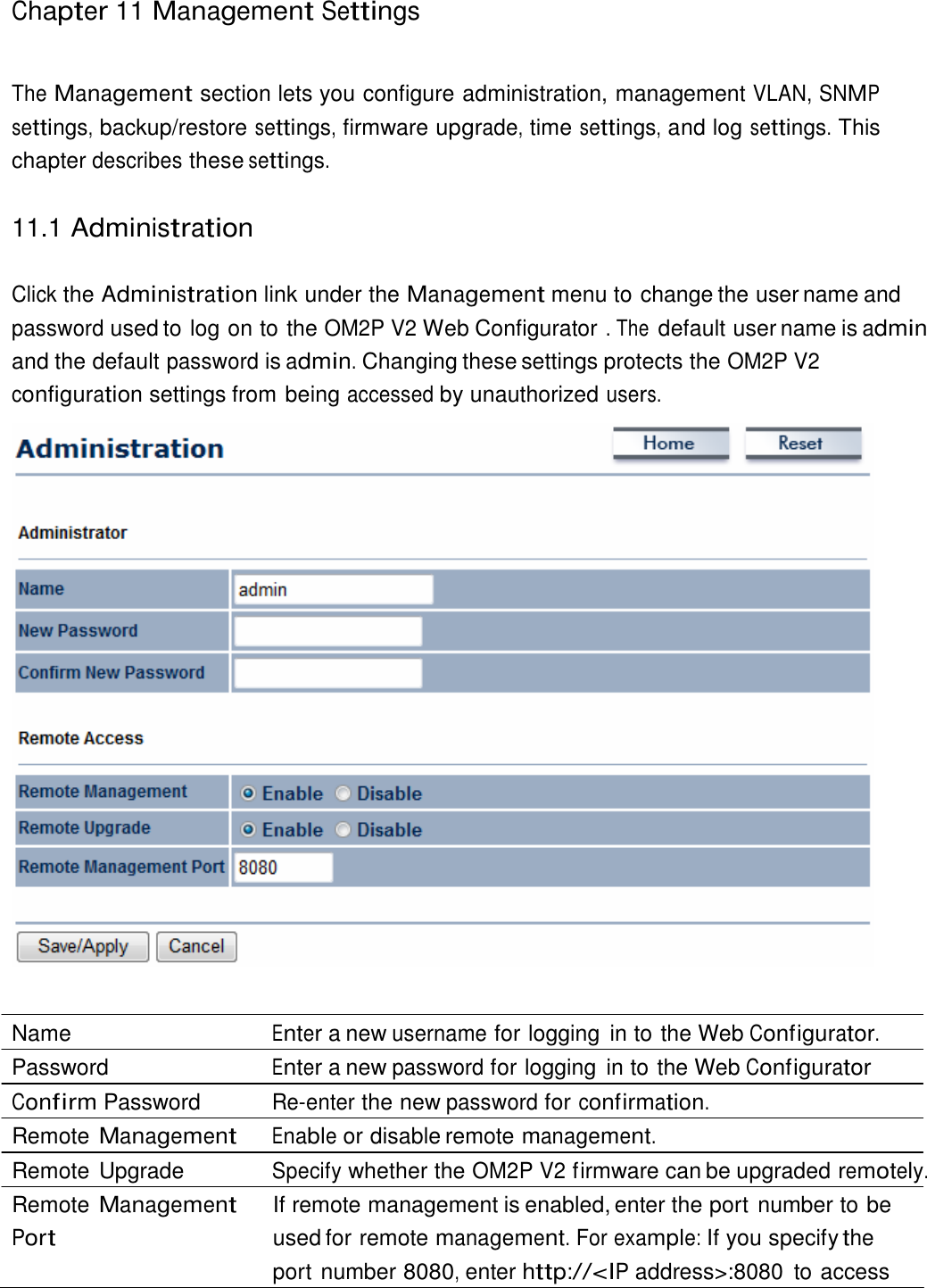
Datto OM2PV2 Wireless 802.11b/g/n Mesh Router User Manual OM2P v2 UM for FCC CE IC apply v2
Open Mesh, Inc. Wireless 802.11b/g/n Mesh Router OM2P v2 UM for FCC CE IC apply v2
UserManual.wiki
>
Datto
>
OM2PV2 User Manual
User Manual_rev.pdf
Navigation menu
Upload a User Manual
Namespaces
Wiki Guide
HTML
PDF
Info
Views
User Manual
Discussion / Help
Navigation
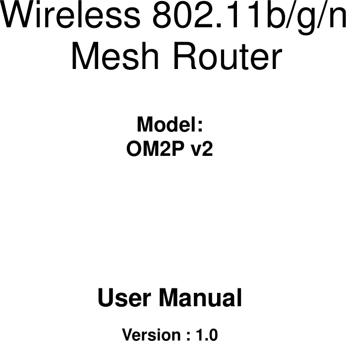
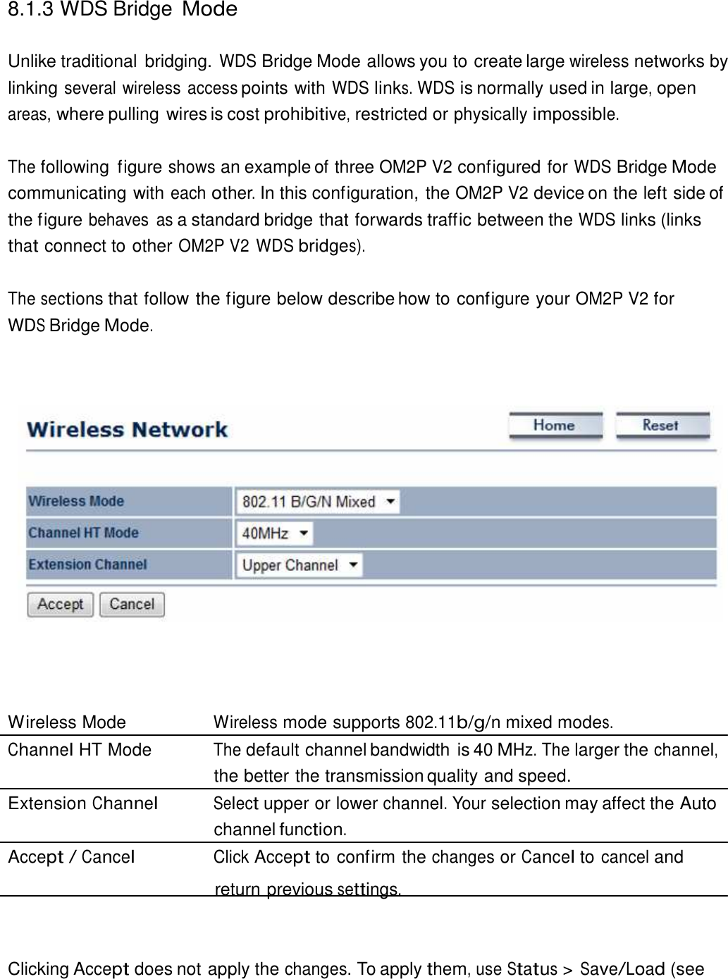
![6.4 System Log ct 19 10:16:58 (none)user.info kernel: mïni fo: u The OM2P V2 automatically logs (records) events of possìble ìnterest ìn ìts ìnternal memory.To vìew the logged ìnformatìonclick the System Log lìnk under the Status drop-down menu.I睡 there ìs not enough ìnternal memory to log all events older events are deleted from the log. System Log Home Resel JY1 AII Oct 19 10:16:58 (none)user.warn kernel: jffs2 build filesystem(): era3ing - r- sing 3torage directory: Oct 19 10:16:58 (none)user.info kernel: mïni fo: using base directory: / Oct 19 10:16:34 (none)user.warn kernel: jffs2 3can eraseblock(): End of f Oct 19 10:16:34 (none)user.warn kernel: jffs2 build filesystem(): unlocki ct 19 10:16:33 (none)user.warn kernel: ar5416SetSwitchComant 3witch co Oct 19 10:16:33 (none)daemon.info dnsmðsq[823]: using local addresses onl Oct 19 10:16:33 (none)daemon.info dnsmðsq[823]: using local addresses onl Oct 19 10:16:33 (none)daemon.info dnsmasq[823): startedve i 2.52 cac'---' Oct 19 10:16:33 (none)daemon.info dnsmasq[823): readinq //resolv.conf Oct 19 10:16:33 (none)daemon.info dnsmasq[823): read /etc/hosts - 1 addre Oct 19 10:16:33 (none)daemon.info dnsmasq[823): compi1e time options: I惱v ct 19 10:16:31 (none)user.info kernel: device athO entered promïscuou3 m Oct 19 10:16:31 (none)user.info kernel: br-lan: topology change detected Oct 19 10:16:31 (none)user.info kernel: br-lan: port 3(athO) entering lea Oct 19 10:16:31 (none)user.info kernel: br-lan: port 3(athO) entering for ct 19 10:16:30 (none)user.warn kernel: osif vap init : wait for connecti Oct 19 10:16:30 (none)user.info kernel: device athO left promïscuou3 mode Oct 19 10:16:30 (none)user.info kernel: br-lan: port 3(athO) entering dis ct 19 10:16:25 (none)user.warn kernel: start running Oct 19 10:16:25 (none)user.warn kernel: set SIOC80211NWID8 characters Oct 19 10:16:25 (none)user.warn kernel: osif vap init 'r1akeup from 'r1ait ( I 111 1 Rerresh 11 Clear l](https://usermanual.wiki/Datto/OM2PV2/User-Guide-2199256-Page-28.png)


![Europe – EU Declaration o This device complies with the essential requirements of the R&TTE Directive 1999/5/EC. The following test methods have been applied in order to prove presumption of conformity with the essential requirements of the R&TTE Directive 1999/5/EC: - EN60950-1 Safety of Information Technology Equipment- - EN50385 - Generic standard to demonstrate the compliance of electronic and electrical apparatus with the basic restrictions related to human exposure to electromagnetic fields (0 Hz - 300 GHz) - - EN 300 328 - Electromagnetic compatibility and Radio spectrum Matters (ERM); Wideband Transmission systems; Data transmission equipment operating in the 2,4 GHz ISM band and using spread spectrum modulation techniques; Harmonized EN covering essential requirements under article 3.2 of the R&TTE Directive EN 301 489-1 Electromagnetic compatibility and Radio Spectrum Matters (ERM); ElectroMagnetic Compatibility (EMC) standard for radio equipment and services; Part 1: Common technical requirements - EN 301 489-17 - Electromagnetic compatibility and Radio spectrum Matters (ERM); ElectroMagnetic Compatibility (EMC) standard for radio equipment and services; Part 17: Specific conditions for 2,4 GHz wideband transmission systems and 5 GHz high performance RLAN equipment 0560 Česky [Czech] [Jméno výrobce] tímto prohlašuje, že tento příslušnými ustanoveními směrnice 1999/5/ES.Dansk [Danish] Undertegnede [fabrikantens navn]overholder de væsentlige krav og øvrige relevante krav i direktiv 1999/5/EF.Deutsch [German] Hiermit erklärt [Name des Herstellers]grundlegenden Anforderungen und den übrigen einschlägigen Bestimmungen der Richtlinie 1999/5/EG befindet. of Conformity This device complies with the essential requirements of the R&TTE Directive 1999/5/EC. The following test methods have been applied in order to prove presumption of conformity with the essential requirements of the R&TTE Directive Safety of Information Technology Equipment Generic standard to demonstrate the compliance of electronic and electrical apparatus with the basic restrictions related to human exposure to electromagnetic Electromagnetic compatibility and Radio spectrum Matters (ERM); Wideband Transmission systems; Data transmission equipment operating in the 2,4 GHz ISM band and using spread spectrum modulation techniques; Harmonized EN covering requirements under article 3.2 of the R&TTE Directive Electromagnetic compatibility and Radio Spectrum Matters (ERM); ElectroMagnetic Compatibility (EMC) standard for radio equipment and services; Part 1: Common Electromagnetic compatibility and Radio spectrum Matters (ERM); ElectroMagnetic Compatibility (EMC) standard for radio equipment and services; Part 17: Specific conditions for 2,4 GHz wideband transmission systems and 5 GHz high equipment 0560 tímto prohlašuje, že tento [typ zařízení] je ve shodě se základními požadavky a dalšími příslušnými ustanoveními směrnice 1999/5/ES. [fabrikantens navn] erklærer herved, at følgende udstyr [udstyrets typebetegnelse]overholder de væsentlige krav og øvrige relevante krav i direktiv 1999/5/EF.[Name des Herstellers], dass sich das Gerät [Gerätetyp] in Übereinstimmung mit dgrundlegenden Anforderungen und den übrigen einschlägigen Bestimmungen der Richtlinie 1999/5/EG This device complies with the essential requirements of the R&TTE Directive 1999/5/EC. The following test methods have been applied in order to prove presumption of conformity with the essential requirements of the R&TTE Directive Generic standard to demonstrate the compliance of electronic and electrical apparatus with the basic restrictions related to human exposure to electromagnetic Electromagnetic compatibility and Radio spectrum Matters (ERM); Wideband Transmission systems; Data transmission equipment operating in the 2,4 GHz ISM band and using spread spectrum modulation techniques; Harmonized EN covering Electromagnetic compatibility and Radio Spectrum Matters (ERM); ElectroMagnetic Compatibility (EMC) standard for radio equipment and services; Part 1: Common Electromagnetic compatibility and Radio spectrum Matters (ERM); ElectroMagnetic Compatibility (EMC) standard for radio equipment and services; Part 17: Specific conditions for 2,4 GHz wideband transmission systems and 5 GHz high je ve shodě se základními požadavky a dalšími [udstyrets typebetegnelse] overholder de væsentlige krav og øvrige relevante krav i direktiv 1999/5/EF. in Übereinstimmung mit den grundlegenden Anforderungen und den übrigen einschlägigen Bestimmungen der Richtlinie 1999/5/EG](https://usermanual.wiki/Datto/OM2PV2/User-Guide-2199256-Page-94.png)
![Eesti [Estonian] Käesolevaga kinnitab [tootja nimi = vastavust direktiivi 1999/5/Esätetele. English Hereby, [name of manufacturer]essential requirements and other relevant provisions of Directive 1999/5/EC.Español [Spanish] Por medio de la presente requisitos esenciales y cualesquierΕλληνική [Greek] ΜΕ ΤΗΝ ΠΑΡΟΥΣΑ [name of manufacturer] ΤΙΣ ΟΥΣΙΩΔΕΙΣ ΑΠΑΙΤΗΣΕΙΣ ΚΑΙ ΤΙΣ ΛΟΙΠΕΣ ΣΧΕΤΙΚΕΣ ΔΙΑΤΑΞΕΙΣ ΤΗΣ ΟΔΗΓΙΑΣ 1999/Français [French] Par la présente [nom du fabricant]essentielles et aux autres dispositions pertinentes de la directive 1999/5/CE.Italiano [Italian] Con la presente [nome del essenziali ed alle altre disposizioni pertinenti stabilite dalla direttiva 1999/5/CE.Latviski [Latvian] Ar šo [name of manufactureratbilst Direktīvas 1999/5/EK būtiskajām prasībām un citiem ar to saistītajiem noteikumiem.Lietuvių [Lithuanian] Šiuo [manufacturer name]1999/5/EB Direktyvos nuostatas.Nederlands [Dutch] Hierbij verklaart [naam van de fabrikant]essentiële eisen en de andere relevante bepalingen van rMalti [Maltese] Hawnhekk, [isem tal-messenzjali u ma provvedimenti oħrajn relevanti li hemm fidMagyar [Hungarian] Alulírott, [gyártó neve] és az 1999/5/EC irányelv egyéb elõírásainakPolski [Polish] Niniejszym [nazwa producenta]oraz pozostałymi stosownymi postanowieniami Dyrektywy 1999/5/EC.Português [Portuguese] [Nome do fabricante] declara que este e outras disposições da DiSlovensko [Slovenian] [Ime proizvajalca] izjavlja, da je ta določili direktive 1999/5/ES.Slovensky [Slovak] [Meno výrobcu] týmto vyhlasuje, že ustanovenia Smernice 1999/5/ES.Suomi [Finnish] [Valmistaja = manufacturer]tyyppinen laite on direktiivin 1999/5/EY oleellisten vaatimusten jehtojen mukainen. Svenska [Swedish] Härmed intygar [företag]egenskapskrav och övriga relevanta bestämmelser som framgår av direktiv 1999/5/EG.[tootja nimi = name of manufacturer] seadme [seadme tüüp = type of equipment]vastavust direktiivi 1999/5/EÜ põhinõuetele ja nimetatud direktiivist tulenevatele teistele asjakohastele [name of manufacturer], declares that this [type of equipment] is in compliance with the essential requirements and other relevant provisions of Directive 1999/5/EC.Por medio de la presente [nombre del fabricante] declara que el [clase de equipo]requisitos esenciales y cualesquiera otras disposiciones aplicables o exigibles de la Directiva 1999/5/CE.[name of manufacturer] ΔΗΛΩΝΕΙ ΟΤΙ [type of equipment] ΤΙΣ ΟΥΣΙΩΔΕΙΣ ΑΠΑΙΤΗΣΕΙΣ ΚΑΙ ΤΙΣ ΛΟΙΠΕΣ ΣΧΕΤΙΚΕΣ ΔΙΑΤΑΞΕΙΣ ΤΗΣ ΟΔΗΓΙΑΣ 1999/[nom du fabricant] déclare que l'appareil [type d'appareil] est conforme aux exigences essentielles et aux autres dispositions pertinentes de la directive 1999/5/CE.[nome del costruttore] dichiara che questo [tipo di apparecchio]essenziali ed alle altre disposizioni pertinenti stabilite dalla direttiva 1999/5/CE.[name of manufacturer / izgatavotāja nosaukums] deklarē, ka [type of equipment / iekārtas tips]atbilst Direktīvas 1999/5/EK būtiskajām prasībām un citiem ar to saistītajiem noteikumiem.[manufacturer name] deklaruoja, kad šis [equipment type] atitinka esminius reikalavimus ir kitas 1999/5/EB Direktyvos nuostatas. [naam van de fabrikant] dat het toestel [type van toestel] in overeenstemming is met de essentiële eisen en de andere relevante bepalingen van richtlijn 1999/5/EG.manifattur], jiddikjara li dan [il-mudel tal-prodott] jikkonforma malessenzjali u ma provvedimenti oħrajn relevanti li hemm fid-Dirrettiva 1999/5/EC. nyilatkozom, hogy a [... típus] megfelel a vonatkozó alapvetõ követelményeknek és az 1999/5/EC irányelv egyéb elõírásainak. [nazwa producenta] oświadcza, że [nazwa wyrobu] jest zgodny z zasadniczymi wymogami oraz pozostałymi stosownymi postanowieniami Dyrektywy 1999/5/EC. declara que este [tipo de equipamento] está conforme com os requisitos essenciais e outras disposições da Directiva 1999/5/CE. izjavlja, da je ta [tip opreme] v skladu z bistvenimi zahtevami in ostalimi relevantnimi določili direktive 1999/5/ES. týmto vyhlasuje, že [typ zariadenia] spĺňa základné požiadavky a všetky príslušné ustanovenia Smernice 1999/5/ES. manufacturer] vakuuttaa täten että [type of equipment = laitteen tyyppimerkintä]tyyppinen laite on direktiivin 1999/5/EY oleellisten vaatimusten ja sitä koskevien direktiivin muiden [företag] att denna [utrustningstyp] står I överensstämmelse med de väsentliga egenskapskrav och övriga relevanta bestämmelser som framgår av direktiv 1999/5/EG.[seadme tüüp = type of equipment] Ü põhinõuetele ja nimetatud direktiivist tulenevatele teistele asjakohastele is in compliance with the essential requirements and other relevant provisions of Directive 1999/5/EC. [clase de equipo] cumple con los a otras disposiciones aplicables o exigibles de la Directiva 1999/5/CE. [type of equipment] ΣΥΜΜΟΡΦΩΝΕΤΑΙ ΠΡΟΣ ΤΙΣ ΟΥΣΙΩΔΕΙΣ ΑΠΑΙΤΗΣΕΙΣ ΚΑΙ ΤΙΣ ΛΟΙΠΕΣ ΣΧΕΤΙΚΕΣ ΔΙΑΤΑΞΕΙΣ ΤΗΣ ΟΔΗΓΙΑΣ 1999/5/ΕΚ. est conforme aux exigences essentielles et aux autres dispositions pertinentes de la directive 1999/5/CE. [tipo di apparecchio] è conforme ai requisiti essenziali ed alle altre disposizioni pertinenti stabilite dalla direttiva 1999/5/CE. pe of equipment / iekārtas tips] atbilst Direktīvas 1999/5/EK būtiskajām prasībām un citiem ar to saistītajiem noteikumiem. atitinka esminius reikalavimus ir kitas in overeenstemming is met de ichtlijn 1999/5/EG. jikkonforma mal-ħtiġijiet Dirrettiva 1999/5/EC. megfelel a vonatkozó alapvetõ követelményeknek jest zgodny z zasadniczymi wymogami está conforme com os requisitos essenciais v skladu z bistvenimi zahtevami in ostalimi relevantnimi spĺňa základné požiadavky a všetky príslušné [type of equipment = laitteen tyyppimerkintä] a sitä koskevien direktiivin muiden står I överensstämmelse med de väsentliga egenskapskrav och övriga relevanta bestämmelser som framgår av direktiv 1999/5/EG.](https://usermanual.wiki/Datto/OM2PV2/User-Guide-2199256-Page-95.png)