Datto OM2PV2 Wireless 802.11b/g/n Mesh Router User Manual OM2P v2 UM for FCC CE IC apply v2
Open Mesh, Inc. Wireless 802.11b/g/n Mesh Router OM2P v2 UM for FCC CE IC apply v2
Datto >
User Manual_rev.pdf

Long Range Wireless N
Client Bridge/Access Point
Wireless 802.11b/g/n
Mesh Router
Model:
OM2P v2
User
Manual
Version :
1.0
T
a
b
l
e
of
C
o
n
t
e
n
t
s
CHAPTER
1
PRODUCT
O
V
E
R
V
IE
W
.............................................................................................................................
7
1.1 F
EATURE
.......................................................................................................................................................................
7
1.2 B
ENEFITS
.......................................................................................................................................................................
8
1.3 P
ACKAGE
C
O
N
T
EN
T
S
......................................................................................................................................................
9
1.3 S
YSTEM
R
EQUIREMENT
..................................................................................................................................................
9
CHAPTER
2
H
AR
D
W
AR
E
O
VER
V
IE
W
........................................................................................................................
10
CHAPTER
3 INSTALLATION
.......................................................................................................................................
11
CHAPTER
4
CONFIGURING YOUR COMPUTER FOR
T
C
P
/
IP
.................................................................................
14
4.1 C
ONFIGURING
M
ICROSOFT
W
INDOWS
7 ............................................................................................................................
15
4.2 C
ONFIGURING
M
ICROSOFT
W
INDOWS
V
I
S
T
A
.......................................................................................................................
17
4.3 C
ONFIGURING
M
ICROSOFT
W
INDOWS
XP
..........................................................................................................................
19
4.4 C
ONFIGURING
M
ICROSOFT
W
INDOWS
2000 ......................................................................................................................
20
4.5 C
ONFIGURING AN
A
PPLE
M
A
CI
N
T
O
S
H
C
O
M
P
U
T
ER
................................................................................................................
22
CHAPTER
5
INTRODUCING THE WEB
C
O
NF
I
G
U
R
A
T
O
R
.....................................................................................................
23
5.1 L
OGGING IN TO THE
W
EB
C
ONFIGURATOR
...........................................................................................................................
23
CHAPTER
6
STATUS ....................................................................................................................................................
25
6.1 S
AVE
/L
OAD
.................................................................................................................................................................
25
6.2
M
AIN
.........................................................................................................................................................................
26
6.3 W
IRELESS
C
LIENT
L
IST
.................................................................................................................................................
27
6.4 S
YSTEM
L
OG
...............................................................................................................................................................
28
6.5 C
ONNECTION
S
TATUS
..................................................................................................................................................
29
6.6 DHCP C
LIENT
T
A
BL
E
...................................................................................................................................................
30
CHAPTER
7
S
Y
S
T
E
M
....................................................................................................................................................
31
7.1 C
HANGING
O
PERATING
M
ODES
...................................................................................................................................
31
CHAPTER
8
W
I
R
E
LESS
CONFIGURATION
................................................................................................................
33
8.1 W
IRELESS
S
ETTINGS
.....................................................................................................................................................
33
8.1.1 Access
Point
Mode ........................................................................................................................................
33
8.1.2
Client
Bridge Mode
.......................................................................................................................................
37
8.1.3
W
D
S
Bridge Mode.........................................................................................................................................
39
8.1.4
Client
R
o
u
t
e
r
M
o
d
e
.......................................................................................................................................
41
8.2 W
IRELESS
S
ECURITY
S
ETTINGS
......................................................................................................................................
43
8.2.1
W
E
P
................................................................................................................................................................
43
8.2.2
W
P
A
-
P
S
K
.......................................................................................................................................................
44
8.2.3
W
P
A
2
-
P
S
K
.....................................................................................................................................................
45
8.2.4
W
P
A
-
P
S
K
Mixed
............................................................................................................................................
46
8.2.5 WPA................................................................................................................................................................
47
8.2.6 WPA2 .............................................................................................................................................................
48
8.2.7 WPA Mixed
....................................................................................................................................................
49
8.4 W
IRELESS
A
DVANCED
S
ET
T
I
N
GS
...................................................................................................................................
50
8.5 W
IRELESS
MAC
F
ILTER
................................................................................................................................................
52
8.6 WDS L
INK
S
ETTINGS
...................................................................................................................................................
53
CHAPTER
9 LAN
S
E
T
U
P
..............................................................................................................................................
54
9.1 IP
S
ET
T
I
N
GS
................................................................................................................................................................
54
9.2 S
PANNING
T
REE
S
ETTINGS
...........................................................................................................................................
55
CHAPTER
10
ROUTER SETTINGS
..............................................................................................................................
56
10.1
WAN
S
ET
T
I
N
GS
........................................................................................................................................................
56
10.1.1
S
t
at
i
c
I
P
........................................................................................................................................................
56
10.1.2 DHCP
(Dynamic
I
P
)
....................................................................................................................................
58
10.1.3 PPPoE
(Point-to-Point
Protocol over
E
t
h
e
rn
e
t
)
........................................................................................
60
10.1.4 PPTP
(Point-to-Point
Tunneling
P
r
o
t
o
c
o
l
)
................................................................................................
62
10.2 LAN S
ETTINGS
(R
OUTER
M
OD
E
)
...............................................................................................................................
64
10.3 VPN P
ASS
T
HR
O
UGH
................................................................................................................................................
65
10.4 P
ORT
F
ORWARDING
..................................................................................................................................................
66
10.5
DMZ
.......................................................................................................................................................................
68
CHAPTER
11
M
AN
A
G
E
M
E
N
T
S
E
TT
IN
G
S
..................................................................................................................
69
11.1 A
DMINISTRATION
......................................................................................................................................................
69
11.2 M
ANAGEMENT
V
L
A
N
...............................................................................................................................................
71
11.3 SNMP
S
ETTINGS
......................................................................................................................................................
72
11.4 B
ACKUP
/R
ESTORE
S
ETTINGS
......................................................................................................................................
73
11.5 F
IRMWARE
U
PGR
A
D
E
.................................................................................................................................................
74
11.6 T
IME
S
ETTINGS
..........................................................................................................................................................
75
11.7 L
OG
..........................................................................................................................................................................
76
11.8 D
IAGNOSTICS
............................................................................................................................................................
77
CHAPTER
12
N
E
T
W
O
R
K
CONFIGURATION
E
X
A
M
PL
E
S
.........................................................................................
78
12.1 A
CCESS
P
OINT
..........................................................................................................................................................
78
12.2 C
LIENT
B
RIDGE
M
OD
E
...............................................................................................................................................
79
12.3 WDS B
RIDGE
M
OD
E
.................................................................................................................................................
80
12.4 C
LIENT
R
O
UT
ER
.........................................................................................................................................................
81
CHAPTER
13 BUILDING A
W
I
R
E
LESS
N
E
T
W
O
R
K
...................................................................................................
81
13.1 A
CCESS
P
OINT
M
ODE
................................................................................................................................................
82
13.2 A
CCESS
P
OINT
M
OD
E
WITH
WDS
F
UN
CT
IO
N
.............................................................................................................
82
13.3 C
LIENT
B
RIDGE
M
OD
E
...............................................................................................................................................
83
13.4 WDS B
RIDGE
M
OD
E
.................................................................................................................................................
83
13.5 C
LIENT
R
OUTER
M
OD
E
..............................................................................................................................................
84
13.6 RADIUS C
ONNECTIONS
...........................................................................................................................................
84
APPENDIX A –
T
R
O
U
B
L
E
S
HOO
T
I
NG
.................................................................................................................................
85
A.1
P
R
O
BL
E
M
S
O
L
V
IN
G
.........................................................................................................................................................
85
A.2 C
ONTACTING
T
ECHNICAL
S
U
PP
O
R
T
....................................................................................................................................
86
APPENDIX B – SPECIFICATIONS
.......................................................................................................................................
87
APPENDIX C – GLOSSARY
................................................................................................................................................
88
APPENDIX D
–
FCC INTERFERENCE
ST
A
T
E
M
E
NT
...............................................................................................................
93

C
a
uti
on
:
This symbol represents the important message on incorrect device
operation that might damage the device
N
ot
e
:
This
symbol
represents
the important
message
for the
s
e
tt
i
n
gs
.
Tip: This symbol represents the alternative choice that can save time
or
r
e
s
our
ce
s
.
A
b
o
u
t
T
h
i
s
D
o
c
um
e
n
t
A
u
d
i
e
n
c
e
This
document is written for networking
professionals
responsible for installing and
m
a
na
g
i
ng
the
E
n
G
e
ni
us
E
N
H
Series
Outdoor
Access
P
oi
nt
/
Br
i
dge
.
To
use
this
g
ui
de
,
you should have
knowledge about
TC
P
/
I
P
and
IEEE
802
.
11
s
t
a
n
da
rd
s
,
and be familiar with the concepts and
terminology
a
ss
oc
i
a
t
e
d
with
wireless
local-area networks
(
W
L
AN
s
)
.
This
document provides the information you need to install and configure your Access
P
oi
nt
/
br
i
dge
.
C
onv
e
n
t
i
o
n
This
publication
uses
these
c
onv
e
nti
ons
/
s
y
m
bol
s
to convey instructions and
i
nfor
m
a
t
i
o
n
and highlight
special
m
e
ss
a
g
e
.

Icons
use
d
Figures
in
t
hi
s
d
oc
um
e
n
t
may use
the
following generic
icons.
EHN device
WLAN signal
Client computer laptop
Internet
Client computer desktop
PoE injector
Power adapter
C
ha
p
t
e
r
1
Pr
od
u
c
t
O
v
e
r
v
i
e
w
Thank you
for
choosing OM2P V2. The OM2P V2 is a long range, high-performance
IEEE
802.11
b
/
g
/
n
network
so
l
u
t
i
on
that
provides Access
P
o
i
n
t
,
C
li
e
n
t
Bridge,
WD
S
,
and
C
li
e
n
t
R
ou
t
e
r
f
un
c
t
i
on
s
in
a single
d
ev
i
c
e
.
In
a
dd
i
t
i
on
to
providing
the
l
a
t
e
s
t
wireless
t
e
c
hno
l
o
gy
,
the
OM2P V2
su
ppo
rt
s
Power over
E
t
h
e
rn
e
t
and Power by
Adapter
c
a
p
a
b
ili
t
i
e
s
,
which allow
the
device
to
be
i
n
s
t
a
ll
e
d
easily
in
nearly any indoor
or
outdoor
l
o
c
a
t
i
on
.
Advanced
f
e
a
t
u
r
e
s
include power level
c
on
t
r
o
l
,
narrow
b
a
nd
w
i
d
t
h
se
l
e
c
t
i
on
,
traffic
shaping, and
R
e
a
l
-
t
i
m
e
RSSI
i
nd
i
c
a
t
i
on
.
A
v
a
ri
e
t
y
of
s
e
c
u
ri
t
y
f
e
a
t
u
r
e
s
help
to
protect your
d
a
t
a
and privacy while you are online.
S
e
c
u
ri
t
y
f
e
a
t
u
r
e
s
include W
i
-
F
i
P
r
o
t
e
c
t
e
d
Access
(
WP
A
-
P
S
K
/
WP
A
2-
P
S
K
),
64
/
128
/
152-
b
i
t
WEP
E
n
c
ry
p
t
i
on
,
and IEEE
802.1x
with
RA
D
I
U
S
.
1.1
F
e
at
u
r
e
The
following
li
s
t
summarizes
the key
features
of the
OM2P V2
:
-
High-speed
data
rates
up to 150
M
bp
s
make the OM2P V2 ideally
suited
for handling heavy data
p
a
y
l
o
a
d
s
such as MPEG
video
s
t
r
e
a
m
i
n
g
-
Fully
Interoperable with
IEEE
802.
11b
/I
EEE
802.
11g
/I
EEE
802.11n-compliant
d
e
v
i
c
e
s
- Multi-function
capabilities
enable
users
to
use
different
modes
in
various
e
n
v
i
ro
n
me
n
t
s
-
P
o
i
n
t
-
t
o
-
po
i
n
t
and
point-to-multipoint
wireless
connectivity enable data
transfers
between two or
mo
re
b
u
il
d
i
n
g
s
-
Channel
bandwidth
selection allows
the appropriate bandwidth to be
used
to
reach various
d
i
s
t
an
c
e
s
-
RSSI
indicator
makes
it
easy
to
s
e
l
e
c
t
the
best signal
for
Access
P
o
i
n
t
c
o
nn
e
c
t
i
o
n
s
-
Power-over-Ethernet capabilities
allow for flexible
i
n
s
t
al
l
at
i
o
n
locations
and
cost
s
a
v
i
n
g
s
-
Four SSIDs
let
clients
access
different
networks
through a
single Access
P
o
i
n
t
,
and
assign
different
po
li
c
i
e
s
and
fu
n
c
t
i
o
n
s
for
each
SS
I
D
-
W
P
A
2/W
P
A
/
W
EP
/
IEEE
802.1x
s
u
ppor
t
and MAC
address
filtering
ensure secure
network
c
o
nn
e
c
t
i
o
n
s
-
PPPoE/PPTP
function
s
u
ppor
t
make it
easy
to
access
the Internet via Internet
Service Provider (ISP)
s
e
r
v
i
c
e
au
t
h
e
n
t
i
c
at
i
o
n
-
SNMP
Remote
Configuration Management
helps administrators
remotely configure or manage the
A
cc
e
ss
P
o
i
n
t
-
QoS
(WMM)
s
u
ppor
t
enhances
performance and
user e
x
p
e
ri
e
n
c
e
s
1.2
B
e
n
e
f
i
t
s
The OM2P V2 is
the
ideal product around which you
can build your WLAN. The following
li
s
t
s
um
m
a
r
i
z
e
s
a
few
key
a
dv
a
n
t
a
g
e
s
that
WLANs have over wired
ne
t
wor
k
s
:
Ideal
for hard-to-wire
e
n
v
i
r
onm
e
n
t
s
There
are
many scenarios
where
cables
c
a
nno
t
be
used
to
c
onn
e
c
t
ne
t
wor
k
i
ng
de
v
i
c
e
s
.
H
i
s
t
or
i
c
and older
buildings,
open
areas, and busy
s
t
r
ee
t
s
,
for
example, make
wired
L
A
N
i
ns
t
a
ll
a
t
i
on
s
difficult,
expensive,
or
i
m
pos
s
i
bl
e.
Temporary
w
o
r
k
g
r
oup
s
WLANs make
it
easy
to
provide
c
o
nne
c
t
i
v
i
t
y
to
temporary workgroups
that will later be
removed. Examples
include
parks,
athletic
arenas,
exhibition
c
e
n
t
e
r
s
,
d
i
s
a
s
t
e
r
-
r
e
c
ov
e
r
y
s
he
l
t
e
r
s
,
temporary
offices, and
c
o
ns
t
r
uc
t
i
on
s
i
t
e
s
.
Ability to
access
r
e
a
l
-
t
i
m
e
i
n
f
o
r
m
a
t
i
on
With a
WLAN, workers
who rely on
access
to
real-time information,
such as
d
oc
t
or
s
and
nurses,
poi
n
t
-
o
f
-
s
a
l
e
employees,
mobile
workers,
and
warehouse personnel,
can
a
cc
e
ss
the data they
need
and
increase
productivity,
without
having
to look for a
place
to plug
into the network.
F
r
e
qu
e
n
t
l
y
changed e
n
v
i
r
onm
e
n
t
s
WLANs
are well
s
ui
t
e
d
for
showrooms,
m
ee
t
i
ng
rooms,
retail
s
t
o
r
e
s
,
and
m
a
nu
f
a
c
t
ur
i
ng
s
i
t
e
s
where workplaces are rearranged
frequently.
Wireless
e
x
t
e
n
s
i
on
s
to
E
t
h
e
r
n
e
t
n
e
t
w
o
r
k
s
WLANs enable
network
managers
in
dynamic
e
n
v
i
r
onm
e
n
t
s
to
m
i
nim
i
z
e
overhead
c
a
us
e
d
by moves, e
x
t
e
ns
i
o
ns
to
ne
t
wor
k
s
,
and
other
c
h
a
nge
s
.
Wired
LAN
backup
Network
managers
can implement
WLANs
to provide backup for
m
i
ss
i
on
-
c
r
i
t
i
c
a
l
a
ppl
i
c
a
t
i
o
ns
running on wired
ne
t
wor
k
s
.
Mobility within
t
r
a
i
n
i
n
g
/
e
du
c
a
t
i
on
a
l
f
a
c
ili
t
i
e
s
Training
s
i
t
e
s
at
c
or
por
a
t
i
ons
and
s
t
u
de
n
t
s
at
u
ni
ve
r
s
i
t
i
e
s
are a
few
examples
where
wireless
c
on
ne
c
t
i
v
i
t
y
can be used
to
facilitate
access
to
information,
information
exchanges, and
learning.

1.3
P
ackage
C
o
n
t
e
n
t
s
Open
the
package carefully and make sure
it
c
on
t
a
i
ns
all of the
i
t
e
m
s
li
s
t
e
d
below.
-
One EnGenius Wireless Access
P
oi
nt
/
Cl
i
e
n
t
Bridge (
OM2P V2
)
If
any
item
is missing
or
damaged,
c
on
t
a
c
t
your place
of
purchase
immediately.
Keep all packing
m
a
t
e
r
i
a
l
s
in
case you need
to return the
OM2P V2. The OM2P V2
m
us
t
be returned
with
i
t
s
original packing
m
a
t
e
r
i
a
l
s
.
Use only
the
power adapter supplied
with
your OM2P V2. Using a
different power
adapter
can damage
the
OM2P V2
.
1.3
S
y
s
t
e
m
R
e
qu
i
r
e
me
n
t
To
i
ns
t
a
ll
the
OM2P V2, you need an
E
t
h
e
r
ne
t
cable and a computer equipped
with:
-
An
E
t
he
r
ne
t
interface
-
One
of the
following o
pe
r
a
t
i
ng
s
y
s
t
e
m
s
:
Microsoft
Windows
XP,
Vi
s
t
a
,
or 7; or
L
i
nux
-
An Internet browser
that
s
up
por
t
s
HTTP and
J
a
v
a
S
c
r
ipt
C
ha
p
t
e
r
2
Hardware
O
v
e
r
v
i
e
w
The following figures show
the
key
c
ompon
e
n
t
s
on the
OM2P V2
.
2.1
Bottom
View
The
bottom
panel
of the
OM2P V2
c
on
t
a
i
ns
two
R
J
-45
po
r
t
s
,
a PoE
i
n
t
e
r
f
a
c
e,
and a
R
e
s
e
t
button. A
removable cover covers
t
he
s
e
c
ompo
ne
n
t
s
.
-
The
R
J
-45
port
c
o
nne
c
t
s
to
an
E
t
h
e
r
ne
t
adapter
in
a computer you use
to
configure
the
OM2P V2.
F
o
r
more information,
see
C
ha
p
t
e
r
4.
-
The PoE
i
n
t
e
r
f
a
c
e
allows
the
OM2P V2
to
be powered using
the
supplied
PoE
injector.
-
The
R
e
s
e
t
button
can be used
to
reboot
the
OM2P V2 and
return the
device
to
i
t
s
default
factory
c
on
f
i
g
ur
a
t
i
on,
erasing any overrides you may have made
to the
d
ev
i
c
e
’
s
default
s
e
tt
i
ng
s
.
T
h
e
R
e
s
e
t
button
is recessed
to
pr
eve
n
t
a
cc
i
de
n
t
a
l
r
e
s
e
t
s
.
To
reboot
the
OM2P V2, use a
flat
object
s
uc
h
as a pencil
to
press
the
R
e
s
e
t
button for
a
p
pr
o
x
i
m
a
t
e
l
y
10 seconds and
then
s
t
op
pressing
the
R
e
s
e
t
button.
2.2 Back
P
a
n
e
l
The back panel
of the
OM2P V2
c
on
t
a
i
ns
the
LED
i
n
di
c
a
t
or
s
that
show
the
link quality and
s
t
a
t
us
of the
OM2P V2
.

C
ha
p
t
e
r
3
I
n
s
t
a
ll
a
t
i
on
This
c
ha
p
t
e
r
describes how
to
i
ns
t
a
ll
the
OM2P V2.
It
also describes
the
OM2P V2
L
E
D
s
.
Only experienced
installation
professionals who are familiar
with
local building and
s
a
f
e
t
y
c
ode
s
a
nd,
wherever applicable, are licensed by
the
appropriate
g
ov
e
r
n
m
e
n
t
r
e
g
ul
a
t
or
y
a
u
t
h
or
i
t
i
e
s
should
i
ns
t
a
ll
the
OM2P V2
.
3.1
P
r
e
-
i
n
s
t
a
ll
a
t
i
o
n
G
u
i
d
e
li
n
e
s
S
e
l
e
c
t
the
optimal
l
oc
a
t
i
ons
for the
equipment
using
the
following
g
ui
de
li
n
e
s
:
-
T
he OM2P V2 should be
mounted
on
a
1"-4"
pole.
I
t
s
l
oc
a
t
i
on
should enable easy access
to the
unit
and
i
t
s
c
on
ne
c
t
or
s
for
installation and
t
e
s
t
i
ng.
-
The higher
the
pl
a
c
e
m
e
n
t
of the
a
n
t
e
n
na,
the better the
achievable link
quality.
-
The
a
n
t
e
n
na
should be
i
ns
t
a
ll
e
d
to
provide a direct,
or
near line
of
s
i
g
h
t
with the
Base
S
t
a
t
i
on
a
n
t
e
nna
.
The
a
n
t
e
nna
should be aligned
to
face
the
general
direction
of the
Base
S
t
a
t
i
on.
3.2 I
n
s
t
a
lli
n
g
the
OM2P V2
To
i
ns
t
a
ll
the
OM2P V2, use
the
following procedure
to
mount
the
device on a pole and refer
to
the
figure
below.
1.
The
bottom of the
OM2P V2 is a movable cover. Grab
the
cover and
pull it
back hard
t
o
remove
the cover.
2.
I
ns
e
r
t
a
s
t
a
nda
r
d
E
t
h
e
r
n
e
t
cable
into the
R
J
-45
port
labeled MAIN
L
AN
.
3.
S
li
de
the
cover back
to
seal
the bottom of the
OM2P V2
.
4.
Remove
the
power cord and
PoE
injector
from the
box and plug
the
power cord
into the
DC
port of the
PoE
injector.
Only use
the
power adapter supplied
with the
OM2P V2. Using a
different power
a
da
p
t
e
r
might
damage
the
OM2P V2
.
5.
Plug
the other
side
of the
E
t
he
r
ne
t
cable
in
s
t
e
p
3 into the
PoE
port of the
PoE
injector.
When you
f
i
ni
s
h
s
t
e
p
5,
the
installation
will
resemble
the
following
picture.
6.
Turn over
the
OM2P V2. Then
i
ns
e
r
t
the
m
a
s
t
s
t
r
a
p
through
the
middle hole
of the
OM2P
V2
.
Use a screwdriver
to
unlock
the
pol
e
-
m
oun
t
i
ng
ring putting
it
through
the
OM2P V2
.
7. Mount the
EOA200 securely
to the
pole by locking
the
s
t
r
a
p
tightly.
This
c
om
pl
e
t
e
s
the
installation
procedure.

3.2
U
nd
e
r
s
t
a
nd
i
n
g
the
OM2P V2
L
E
Ds
The rear
of the
OM2P V2 has
two
groups
of
LEDs.
One group, labeled INDICATORS, shows
the
s
t
a
t
us
of the
device. The second group, LINK QUALITY, shows
the
s
t
r
eng
t
h
of the
link
be
t
w
ee
n
the
OM2P
V2
and the
network.
The following
t
a
bl
e
describes
the
OM2P V2
L
E
D
s
.
L
E
D
Color Mode
S
t
a
t
us
P
ow
e
r
Green
OFF=
OM2P V2 is
not
receiving
power.
ON= OM2P V2 is receiving
power.
L
A
N
Green
OFF
= OM2P V2 is
not
c
onn
e
c
t
e
d
to the network.
ON = OM2P V2 is
c
on
ne
c
t
e
d
to the
network,
but not
sending
or
receiving
data.
Blink = OM2P V2 is sending
or
receiving
data.
W
L
A
N
Green
Access
P
oi
n
t
or
Cl
i
e
n
t
Bridge
Mode
OFF
= OM2P V2 radio is
off
and
the
device is
not
sending
or
receiving
da
t
a
over
the
wireless
L
A
N.
ON = OM2P V2 radio is on, and
the
device is
not
s
e
nd
i
ng
or
receiving
da
t
a
over
the
wireless
L
A
N.
Blink = OM2P V2 radio is on, and
the
device is
s
e
ndi
n
g
or
receiving
da
t
a
over
the
wireless
L
A
N.
Link
Quality
See
S
t
a
t
us
column
Access
P
oi
n
t
or
Cl
i
e
n
t
Bridge
Mode
S
how
s
the
s
t
r
eng
t
h
of the
link
be
t
w
ee
n
the
OM2P V2
and
the network.
G = good
quality
(green).
Y
= medium quality
(ye
ll
ow)
.
R = poor
or no
link
(red).
Chapter
4
Configuring
Your
Computer
for TCP
/l
P
To
configure the
OM2P V2
use
a computer that is configured for
TCP/IP.
This chapter describes how
to
configure the
TCP/IP
settings on a computer that will be used to configure the OM2P V2.
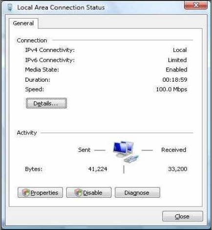
4.1
C
on
fi
g
u
r
i
n
g
M
i
c
r
o
s
o
ft
Windows
7
Use
the
following procedure
to
configure a
computer running Microsoft W
i
nd
ow
s
7.
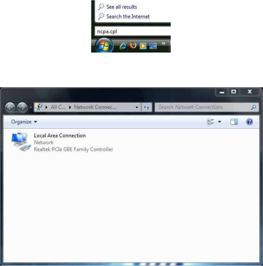
1. In the
S
t
a
r
t
menu search box,
type:
ncpa.cpl
2.
When
the
Network
Co
nn
e
c
t
i
ons
L
i
s
t
appears,
r
i
g
h
t
-
c
li
c
k
the
L
o
c
a
l
Area
Co
nn
e
c
t
i
on
icon
and click Pr
op
e
r
t
i
e
s
.
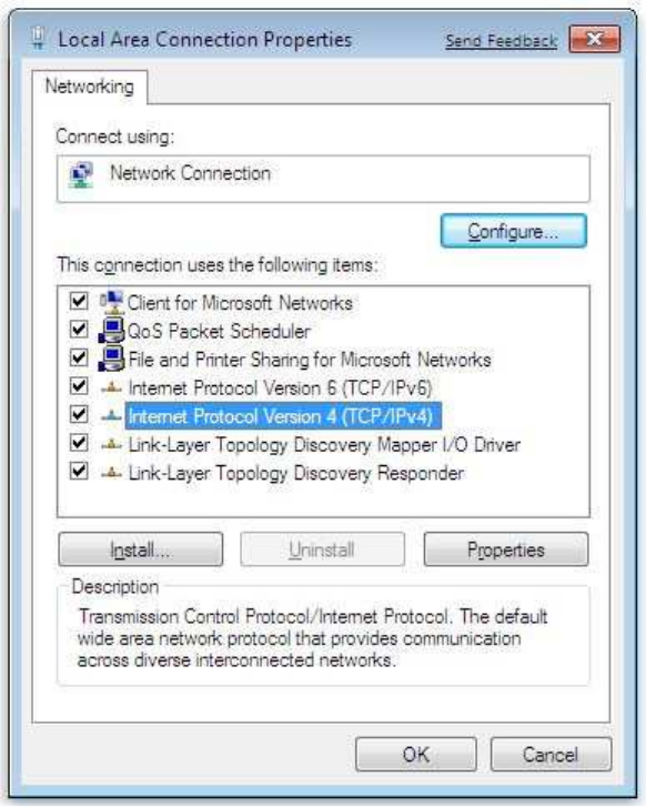
3. In the
Ne
t
wor
k
i
ng
t
a
b,
click
either Internet
P
r
o
t
oc
ol
Version
4
(
T
CP
/
I
P
v
4
)
or Internet
P
r
ot
oc
o
l
Version
6
(
T
CP
/
I
P
v
6
),
and then
click
P
r
op
e
r
t
i
e
s
.
4. In the
pr
o
pe
r
t
i
e
s
dialog box, click
O
b
t
a
i
n
an IP address a
u
t
om
a
t
i
c
a
ll
y
to
configure
your
computer
for
D
H
CP
.
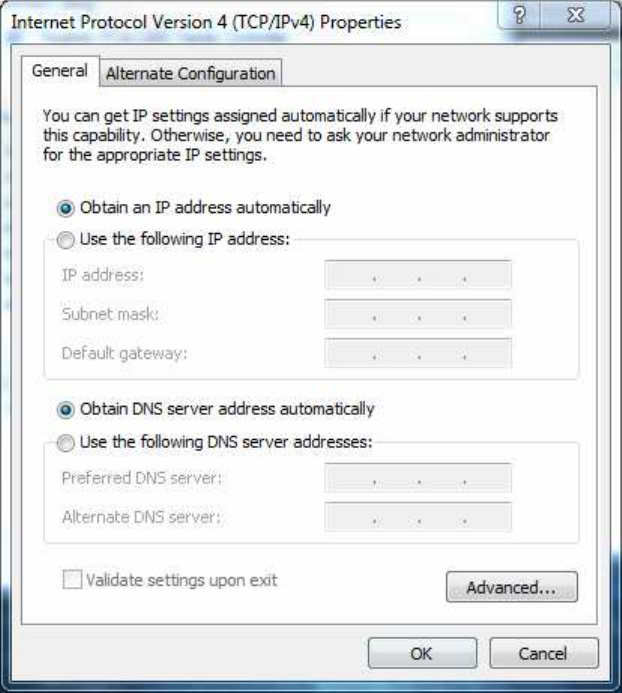
5.
Click
the
OK
button to
save your changes and close
the
dialog
box.
6.
Click
the
OK
button
again
to
save your
c
h
a
nge
s
.
4.2
C
on
fi
g
u
r
i
n
g
M
i
c
r
o
s
o
ft
Windows
V
i
s
t
a
Use
the
following procedure
to
configure a
computer running Microsoft W
i
nd
ow
s
V
i
s
t
a
with the
default
i
n
t
e
r
f
a
c
e.
If
you use
the
Cl
a
ss
i
c
i
n
t
e
r
f
a
c
e,
where
the
icons and menus resemble
previous
W
i
ndow
s
versions, perform
the
procedure
in
s
e
c
t
i
on
4.4.
1.
On
the
Windows
t
a
s
kba
r
,
click
S
t
a
r
t
,
click
Co
n
t
r
o
l
Pa
n
e
l
,
and then
s
e
l
e
c
t
the Network
and
Internet icon.
2.
Click View
N
e
t
w
o
r
k
s
S
t
a
t
u
s
and
t
a
s
k
s
and then
click
M
a
n
a
g
e
m
e
n
t
N
e
t
w
o
r
k
s
Co
nn
e
c
t
i
on
s
.
3.
R
i
g
ht
-
c
li
c
k
the
L
o
c
a
l
Area
Co
nn
e
c
t
i
on
icon and click Pr
op
e
r
t
i
e
s
.
4.
Click
Co
n
t
i
nu
e.
The Local Area
Co
nne
c
t
i
on
P
r
ope
r
t
i
e
s
dialog box
a
ppe
a
r
s
.
5. In the
Local Area
Con
ne
c
t
i
on
P
r
o
pe
r
t
i
e
s
dialog box, verify
that Internet Protocol
(TCP/IPv4) is checked. Then
s
e
l
e
c
t
Internet
P
r
o
t
o
c
o
l
(TCP/IPv4) and click
the
Pr
op
e
r
t
i
e
s
button.
The
Internet
P
r
o
t
oc
ol
Version
4
P
r
o
pe
r
t
i
e
s
dialog box
a
pp
e
a
r
s
.
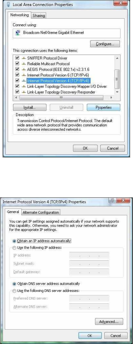
6. In the
Internet
P
r
ot
oc
ol
Version
4
P
r
o
pe
r
t
i
e
s
dialog box, click
O
b
t
a
i
n
an IP a
dd
r
e
ss
a
u
t
om
a
t
i
c
a
ll
y
to
configure your computer
for
D
H
CP
.
7.
Click
the
OK
button to
save your changes and close
the
dialog
box.
8.
Click
the
OK
button
again
to
save your
c
hange
s
.
4.3
C
on
fi
g
u
r
i
n
g
M
i
c
r
o
s
o
ft
Windows
X
P
Use
the
following procedure
to
configure a
computer running Microsoft W
i
nd
ow
s
XP
with the default
i
n
t
e
r
f
a
c
e.
If
you use
the
Cl
a
ss
i
c
i
n
t
e
r
f
a
c
e,
where
the
icons and menus resemble previous
W
i
nd
ow
s
versions, perform
the
procedure
in
s
e
c
t
i
on
4.4.
1.
On
the
Windows
t
a
s
kba
r
,
click
S
t
a
r
t
,
click
Co
n
t
r
o
l
Pa
n
e
l
,
and then
click
Network and
Internet
Co
nn
e
c
t
i
on
s
.
2.
Click
the
Network
Con
ne
c
t
i
ons
icon.
3.
Click
L
o
c
a
l
Area
Co
nn
e
c
t
i
on
for the
E
t
h
e
r
ne
t
adapter
c
on
ne
c
t
e
d
to the
OM2P V2. The
L
oc
a
l
Area
Con
n
e
c
t
i
on
S
t
a
t
us
dialog box
a
ppe
a
r
s
.
4. In the
Local Area
Con
ne
c
t
i
on
S
t
a
t
us
dialog box, click
the
Pr
op
e
r
t
i
e
s
button.
The
L
oc
a
l
Area
Con
ne
c
t
i
on
P
r
o
pe
r
t
i
e
s
dialog box
a
p
pe
a
r
s
.
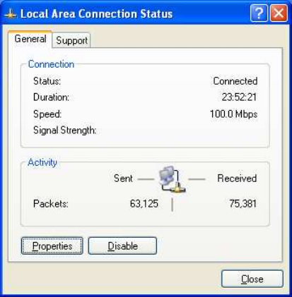
5. In the
Local Area
Con
ne
c
t
i
on
P
r
o
pe
r
t
i
e
s
dialog box, verify
that Internet
Pr
o
t
o
c
o
l
(
T
CP
/
I
P)
is checked. Then
s
e
l
e
c
t
Internet
P
r
o
t
o
c
o
l
(TCP/IP) and click
the
Pr
op
e
r
t
i
e
s
button.
T
he
Internet
P
r
o
t
oc
ol
(
T
CP
/
I
P
)
P
r
ope
r
t
i
e
s
dialog box
a
ppe
a
r
s
.
6. In the
Internet
P
r
ot
oc
ol
(
T
CP
/
I
P
)
P
r
ope
r
t
i
e
s
dialog box, click
O
b
t
a
i
n
an IP a
dd
r
e
ss
a
u
t
om
a
t
i
c
a
ll
y
to
configure your computer
for
DHCP.
Click
the
OK
button to
save
t
hi
s
change and close
the
Internet
P
r
ot
oc
ol
(
T
CP
/
I
P
)
P
r
ope
r
t
i
e
s
dialog
box.
7.
Click
the
OK
button
again
to
save your
c
hange
s
.
8.
R
e
s
t
a
r
t
your
computer.
4.4
C
on
fi
g
u
r
i
n
g
M
i
c
r
o
s
o
ft
Windows
2000
Use
the
following procedure
to
configure your
computer
if
your computer
has
Microsoft
W
i
nd
ow
s
2000
installed.
1.
On
the
Windows
t
a
s
kba
r
,
click
S
t
a
r
t
,
point to
S
e
tt
i
n
g
s
,
and then
click
Co
n
t
r
o
l
Pa
n
e
l
.
2. In the
Control Panel window, double-click
the Network
and Dial-up
Co
nn
e
c
t
i
on
s
icon.
If
the
E
t
he
r
ne
t
adapter
in
your computer
is
i
ns
t
a
ll
e
d
c
or
r
e
c
t
l
y,
the
Local Area
Connection
icon
a
p
pe
a
r
s
.
3.
Double-click
the
L
o
c
a
l
Area
Co
nn
e
c
t
i
on
icon
for the
E
t
he
r
ne
t
a
da
p
t
e
r
c
on
ne
c
t
e
d
to the
OM2P V2. The Local Area
C
onne
c
t
i
on
S
t
a
t
us
dialog box
a
p
pe
a
r
s
.
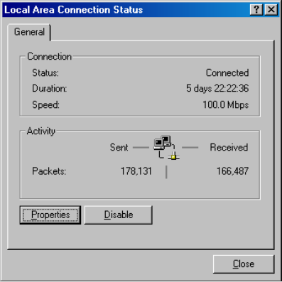
4. In the
Local Area
Con
ne
c
t
i
on
S
t
a
t
us
dialog box, click
the
Pr
op
e
r
t
i
e
s
button.
The
L
oc
a
l
Area
Con
ne
c
t
i
on
P
r
o
pe
r
t
i
e
s
dialog box
a
p
pe
a
r
s
.
5. In the
Local Area
Con
ne
c
t
i
on
P
r
o
pe
r
t
i
e
s
dialog box, verify
that Internet
Pr
o
t
o
c
o
l
(
T
CP/
I
P)
is checked. Then
s
e
l
e
c
t
Internet
P
r
o
t
o
c
o
l
(TCP/IP) and click
the
Pr
op
e
r
t
i
e
s
button.
6.
Click
O
b
t
a
i
n
an IP address a
u
t
om
a
t
i
c
a
ll
y
to
configure
your computer
for
D
H
CP
.
7.
Click
the
OK
button to
save
t
hi
s
change and close
the
Local Area
Con
ne
c
t
i
on
P
r
ope
r
t
i
e
s
dialog
box.
8.
Click OK
button
again
to
save
t
h
e
s
e
new
c
hange
s
.
9.
R
e
s
t
a
r
t
your
computer.
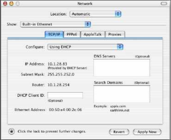
4.5
C
o
n
fi
g
u
r
i
n
g
a
n
Apple
M
a
c
i
n
t
o
s
h
C
o
m
p
u
t
e
r
The following procedure describes how
to
configure
T
C
P
/
I
P
on an Apple
M
a
c
i
n
t
os
h
running Mac
O
S
10.2.
If
your Apple
M
a
c
i
n
t
os
h
is running Mac
OS 7.x
or
later,
the
s
t
e
ps
you perform and
the
s
c
r
ee
ns
you see may
differ
s
li
g
h
t
l
y
from the
following. However, you should
s
t
ill
be able
to
use
t
hi
s
procedure
as a guide
to
configuring your Apple
M
a
c
i
n
t
os
h
for
T
CP
/
I
P
.
1.
Pull down
the
Apple Menu, click
S
y
s
t
e
m
Pre
f
e
r
e
n
c
e
s
,
and
s
e
l
e
c
t
Network.
2.
Verify
that the
NIC c
onn
e
c
t
e
d
to the
OM2P V2 is
s
e
l
e
c
t
e
d
in the
S
ho
w field.
3. In the
C
on
f
i
g
u
r
e
field on
the
TCP/IP
t
a
b
,
s
e
l
e
c
t
Us
i
n
g
DHCP
.
4.
Click
Apply Now
to
apply your
s
e
tt
i
ng
s
and close
the
T
CP
/
I
P
dialog
box.
C
h
a
p
t
e
r
5
In
t
r
odu
c
i
n
g
t
h
e
Web
C
o
n
fi
g
u
r
a
t
o
r
The OM2P V2 has a
built-in
Web
Con
f
i
g
ur
a
t
or
that
l
e
t
s
you manage
the unit from
any
l
oc
a
t
i
on
using
a
Web
br
ow
s
e
r
that
s
uppo
r
t
s
HTTP and has
J
a
v
a
S
c
r
ipt
installed.
5.1
L
o
gg
i
n
g
in
to
t
h
e
Web
C
on
f
i
g
u
r
a
t
o
r
After
configuring
the
computer
for
T
CP
/
I
P
using
the
procedure
appropriate
for
your o
pe
r
a
t
i
ng
s
y
s
t
e
m
,
use
that
c
omp
ut
e
r
’
s
Web
br
ow
s
e
r
to
log
in to the
OM2P V2 Web
Configurator.
1. Launch your Web
br
o
w
s
e
r
.
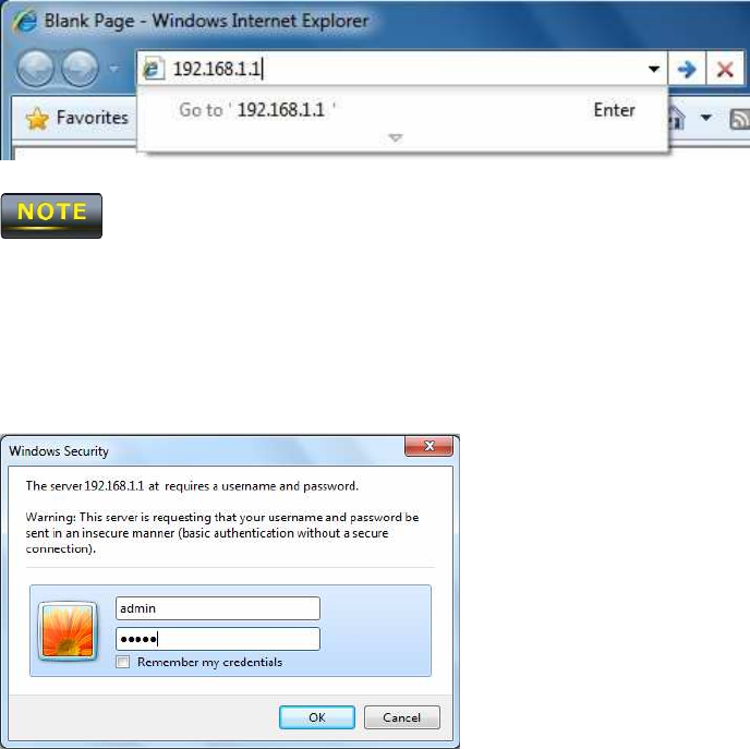
2. In
the
br
ow
s
e
r
address
bar, type
192.168.1.1 and press
the
E
n
t
e
r
key.
If
you changed
the
OM2P V2 LAN IP address,
enter
the
c
or
r
e
c
t
IP
a
d
dr
e
ss
.
3. When
the
W
i
nd
ow
s
S
e
c
ur
i
t
y
window appears,
type admin
as
the
username
in the top
field
and
type admin
as
the
password
in the bottom field.
4. Click O
K
You are now ready
to
use
the
i
ns
t
r
uc
t
i
o
ns
in the
following
c
ha
p
t
e
r
s
to
configure
the
OM2P V2
.
5.2
B
e
s
t
P
r
a
c
ti
c
e
s
P
e
r
f
or
m
the
following procedures regularly
to
make
the
OM2P V2 more secure and manage
the
OM2P
V2
more
effectively.
-
Change
the default
password. Use a password
that
is
not
easy
to
guess and
that
c
on
t
a
i
n
s
different
c
ha
r
a
c
t
e
r
s
,
such as numbers and
l
e
tt
e
r
s
.
The OM2P V2 username
c
a
nno
t
be changed.
F
or
more information,
see page
69.
-
Back
up the
c
on
f
i
g
u
r
a
t
i
on
and be sure you know how
to
r
e
s
t
or
e
it.
R
e
s
t
or
i
ng
an earlier
working
c
on
f
i
g
ur
a
t
i
on
can be useful
if the
OM2P V2 becomes uns
t
a
bl
e
or
crashes.
If
you forget your
p
a
ss
w
o
r
d
,
you
will
have
to
r
e
s
e
t
the
OM2P V2
to
i
t
s
f
a
c
t
or
y
default
s
e
tt
i
ng
s
and lose any
c
us
t
om
i
z
e
d
override
s
e
tt
i
ng
s
you configured. However,
if
you back up an earlier
c
on
f
i
g
ur
a
t
i
on,
you
will not
have
t
o
c
om
pl
e
t
e
l
y
reconfigure
the
OM2P V2. You can simply
r
e
s
t
o
r
e
your
l
a
s
t
c
on
f
i
g
u
r
a
t
i
on.
For
more
information,
see page
73.
C
ha
p
t
e
r
6
S
t
a
t
u
s
The
S
t
a
t
u
s
s
e
c
t
i
on
on
the
nav
i
g
a
t
i
on
drop-down menu
c
on
t
a
i
ns
the
following
options:
-
Main
-
Wireless
Cl
i
e
n
t
L
i
s
t
-
S
y
s
t
e
m
L
og
-
Conne
c
t
i
on
S
t
a
t
us
The following sections describe these options.
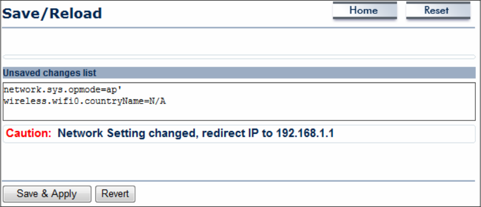
6.1
Sa
v
e
/
L
o
a
d
This
page lets you
save
and apply the settings shown under Unsaved changes
li
s
t
,
or cancel
the
unsaved changes
and revert to the previous settings that were in
e
ff
ec
t
.
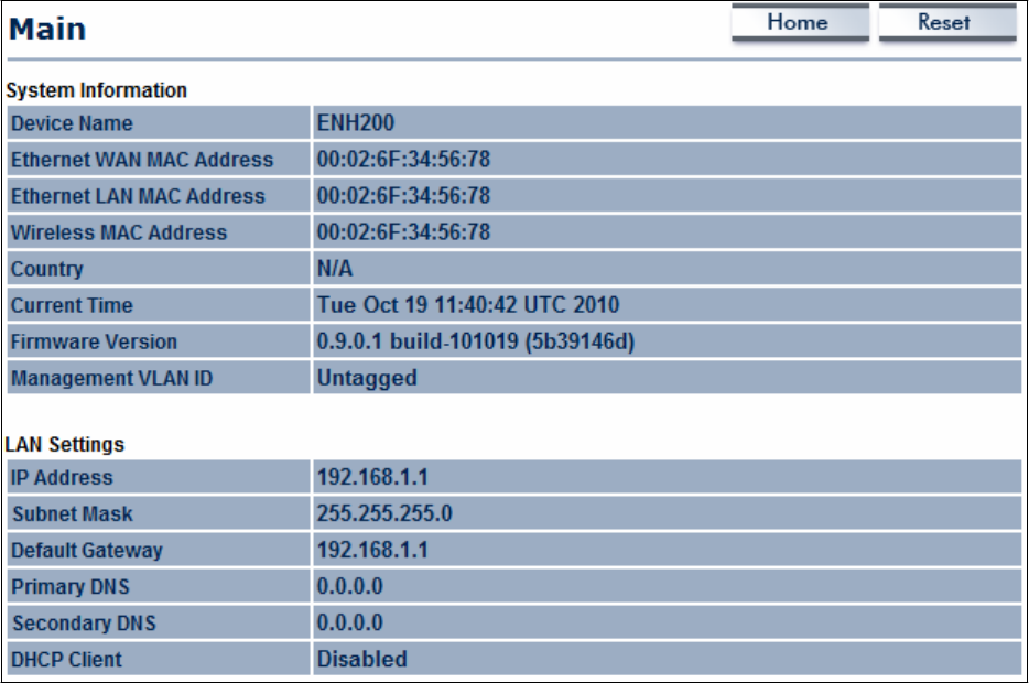
6.2
M
a
in
Clicking the
Main
link under the
S
t
a
t
u
s
drop-down menu or clicking Home at the
t
op
-
r
ight
of the Web Configurator
shows
status information about the current operating
m
ode
.
-
The
S
y
s
t
e
m
Information
section
shows
general
s
y
s
t
e
m
information such
as
ope
r
a
t
i
ng
m
ode
,
s
y
s
t
e
m
up
t
i
m
e
,
firmware
version, serial
num
be
r
,
kernel
v
e
r
s
i
on
,
and
a
ppl
i
ca
t
i
on
v
e
r
s
i
on
.
-
The
LAN
S
e
tt
i
n
g
s
section
shows Local
Area Network setting such
as
the LAN
IP
a
ddr
e
ss
,
subnet
mask,
and MAC
a
ddr
e
ss
.
-
The
C
u
rr
e
n
t
Wireless
S
e
tt
i
n
g
s
section
shows wireless
information such
as
frequency and
c
ha
nne
l
.
Since
the
OM2P V2
supports
mul
t
i
pl
e
-
S
SI
D
s
,
information about
each SSID,
such
as its
ESSID
and security
s
e
tt
i
ngs
,
are displayed.
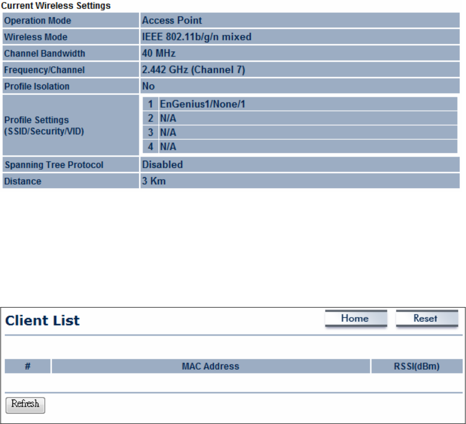
6.3
Wireless
C
lie
n
t
L
is
t
Clicking the Wireless
C
li
e
n
t
L
i
s
t
link under the
S
t
a
t
u
s
drop-down menu
displays
the list
of
clients
a
ss
oc
i
a
t
e
d
to the
OM2P V2
,
along with the MAC
addresses
and signal strength for
each
c
li
e
nt
.
Clicking the
Re
f
r
e
s
h
button updates
(refreshes)
the client
li
s
t
.

6.4
System
Log
c
t
19
1
0
:
1
6
:
5
8
(
n
o
n
e
)
u
se
r
.
i
n
f
o
kernel: mïni
f
o
:
u
The
OM2P V2 automatically
logs (records) events of possìble ìnterest ìn ìts ìnternal
memory.
To
vìew
the logged ìnformatìon
click
the System Log
lìnk
under the
Status
drop-
down
menu.
I睡
there ìs not enough ìnternal memory to log all events older events are deleted from the
log.
System Log
Home
Rese
l
JY1
A
II
Oct
19
1
0
:
1
6
:
5
8
(
n
o
n
e
)
u
se
r
.
w
a
r
n
kernel: jffs2 build
f
il
es
y
ste
m
(
)
:
e
ra
3
i
n
g
-
r-
sing 3torage
dir
e
c
t
o
r
y
:
Oct
19
1
0
:
1
6
:
5
8
(
n
o
n
e
)
u
se
r
.
i
n
f
o
kernel: mïni fo: using
base
dir
e
c
t
o
r
y
:
/
Oct
19
1
0
:
1
6
:
3
4
(
n
o
n
e
)
u
se
r
.
w
a
r
n
kernel: jffs2 3can
e
ra
se
b
l
oc
k
(
)
:
E
n
d
of f
Oct
19
1
0
:
1
6
:
3
4
(
n
o
n
e
)
u
se
r
.
w
a
r
n
kernel: jffs2 build
f
il
es
y
ste
m
(
)
:
unlocki ct 19 10:16:33
(
n
o
n
e
)
u
se
r
.
w
a
r
n
kernel: a
r5
41
6
S
et
Sw
i
t
c
h
Com
a
n
t
3witch co
Oct
19 10:16:33
(
n
o
n
e
)
da
e
m
o
n
.
i
n
f
o
d
n
s
mð
s
q
[
8
23
]
:
using
local addresses
o
n
l
Oct
19 10:16:33
(
n
o
n
e
)
da
e
m
o
n
.
i
n
f
o
d
n
s
mð
s
q
[
8
23
]
:
using
local addresses
o
n
l
Oct
19 10:16:33
(
n
o
n
e
)
da
e
m
o
n
.
i
n
f
o
d
n
s
ma
s
q
[
8
23
)
:
sta
r
te
d
v
e
i
2.52
c
a
c
'---'
Oct
19 10:16:33
(
n
o
n
e
)
da
e
m
o
n
.
i
n
f
o
d
n
s
ma
s
q
[
8
23
)
:
readinq
/
/
r
es
o
l
v
.
co
n
f
Oct
19 10:16:33
(
n
o
n
e
)
da
e
m
o
n
.
i
n
f
o
d
n
s
ma
s
q
[
8
23
)
:
read
/etc/hosts - 1
addr
e
Oct
19 10:16:33
(
n
o
n
e
)
da
e
m
o
n
.
i
n
f
o
d
n
s
ma
s
q
[
8
23
)
:
compi1e time
options:
I
惱v
ct 19
1
0
:
1
6
:
3
1
(
n
o
n
e
)
u
se
r
.
i
n
f
o
kernel: device
athO
entered
promïscuou3
m
Oct
19
1
0
:
1
6
:
3
1
(
n
o
n
e
)
u
se
r
.
i
n
f
o
kernel: br-lan: topology change
d
ete
c
te
d
Oct
19
1
0
:
1
6
:
3
1
(
n
o
n
e
)
u
se
r
.
i
n
f
o
kernel: br-lan:
port
3(athO) entering
l
ea
Oct
19
1
0
:
1
6
:
3
1
(
n
o
n
e
)
u
se
r
.
i
n
f
o
kernel: br-lan:
port
3(athO)
e
n
te
ri
n
g
for ct 19
1
0
:
1
6
:
3
0
(
n
o
n
e
)
u
se
r
.
w
a
r
n
kernel: osif
vap
init
: wait
f
o
r
connecti
Oct
19
1
0
:
1
6
:
3
0
(
n
o
n
e
)
u
se
r
.
i
n
f
o
kernel: device
athO
l
eft
promïscuou3
m
o
de
Oct
19
1
0
:
1
6
:
3
0
(
n
o
n
e
)
u
se
r
.
i
n
f
o
kernel: br-lan:
port
3(athO)
e
n
te
ri
n
g
dis
ct 19 10:16:25
(
n
o
n
e
)
u
se
r
.
w
a
r
n
kernel:
start
r
u
nn
i
n
g
Oct
19 10:16:25
(
n
o
n
e
)
u
se
r
.
w
a
r
n
kernel:
set
SI
OC
80
2
11
NW
I
D
8
characters
Oct
19 10:16:25
(
n
o
n
e
)
u
se
r
.
w
a
r
n
kernel: osif
vap
init
'r1
akeup from
'r1
a
i
t
( I
111
1
Rerresh
11
C
l
ear
l
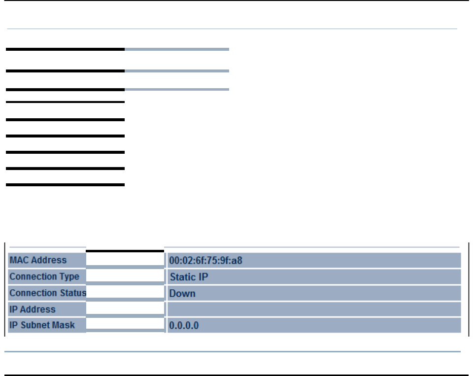
6.5
Conneetion
StatU$
Clicking
the Connection
Status
link under the
Stat
drop-down menu
displays
the current
status of the networ
k。
The information shown includes
network
type
SSID
BSSID
connection
status
wireless
mode current channel
securit
y
data
rate
noise level and signal
strength.
W
i
r
e
l
ess
Netwo
Type
I
l司
lie
n
t
Router
SS
I
D
IIEnGenius
BSS
I
D
I
Connection
S
s
W
i
re
ss
Mode
Current
Channe
l
S
urity
Tx
Da Ra
Mbps)
Current
n
se
ve
l
S
na
l
strength
WAN
I
Refl
:es
h
I

6.6
DHCP
Client
Table
Clicking
the DHCP Client List link under the
Status drop-down
menu displays the clients
that
are associated
to
the OM2P V2 through
DHCP.The MAC
addresses
and signal strength for
each
client are also shown.
Clicking
the Refresh button
updates
(refreshes) the client lis
t。
DHCP
Client list
Home Resel
MAC
addr
11
I
Refl
:es
h
I
IP
11
Ex
pires
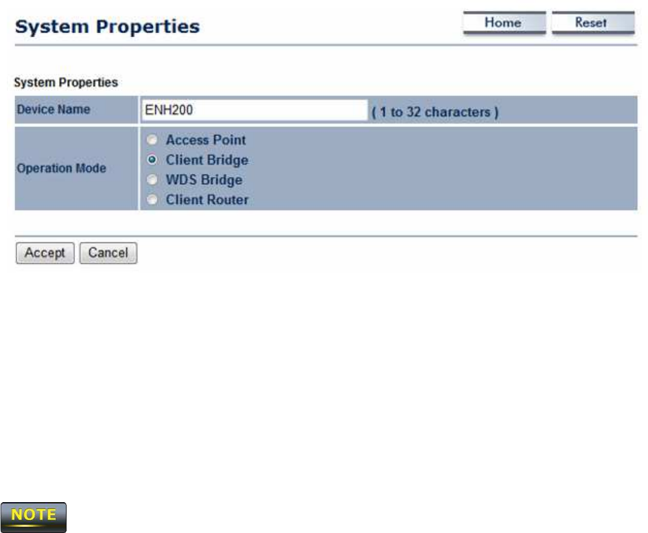
C
ha
p
t
e
r
7
Sy
s
t
e
m
This
c
ha
p
t
e
r
describes how
to
change
the
OM2P V2
op
e
r
a
t
i
ng
m
od
e
s
.
7.1 Changing
O
p
e
r
a
t
i
n
g
M
ode
s
The OM2P V2
supports four operating
m
ode
s
:
-
Access
P
oi
nt
-
Client Bridge
-
WDS
Bridge
-
Client
R
out
e
r
To
s
e
l
ec
t
an operating
m
ode
,
click
S
y
s
t
e
m
Pr
op
e
r
t
i
e
s
under
S
y
s
t
e
m
S
ec
t
i
on
.
Then
go to
S
y
s
t
e
m
>
O
p
e
r
a
t
i
on
mod
e
.
.
Device
N
a
m
e
:
E
nt
e
r
a name for the
de
v
i
ce
.
The
name you type
appears
in
SN
M
P
m
a
na
ge
m
e
nt
.
This
name is not the
SSID
and is not broadcast to other
de
v
i
ce
s
.
O
p
e
r
a
t
i
on
M
od
e
:
Use
the radio button to
s
e
l
ec
t
an operating
m
ode
.
To
use Access
P
oi
nt
mode with
WDS,
s
e
l
ec
t
Access
P
oi
n
t
here and then enable the
WDS
function in the Wireless
Network section
(see
section
8
.
6
)
.
Click
A
cce
p
t
to confirm the
c
ha
nge
s
.
Clicking
Accept does not apply the changes.
To
apply them
use
Status
>
Save/Load
(
see
section 4.1)
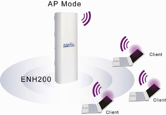
C
ha
p
t
e
r
8
Wireless
C
on
f
igu
r
a
t
i
on
This
chapter
describes
the
OM2P V2’s wireless
s
e
tt
i
ngs
.
Please
read the information in
t
hi
s
chapter
ca
r
e
f
ul
l
y
.
If you configure a setting
i
m
pr
ope
r
l
y
,
it can impact performance and affect
the network
adversely.
Before you
c
onti
nue
,
be sure you
s
e
l
ec
t
e
d
the appropriate ope
r
a
t
i
ng
mode
(see
Chapter
7
)
.
8.1
Wireless
Se
tt
i
n
gs
This
section
describes basic wireless
s
e
tt
i
ngs
.
For
more information,
see
Chapter
12
.
8.1.1
Access
P
oin
t
Mode
The OM2P V2
supports
Access
P
oi
nt
M
ode
.
In this
m
ode
,
users
with a
wireless
client device
within range can connect to the
OM2P V2
to
access
the
WLAN. The
following figure
shows
an example of an
OM2P V2
operating in
Access
P
oi
nt
M
ode
.
The
s
ec
t
i
ons
that follow the figure below describe how to configure your
OM2P V2
for
Access
P
oi
nt
M
ode
.
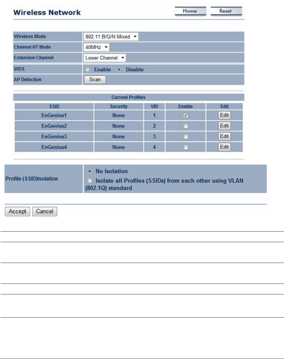
Wireless Mode
Wireless
mode supports
802
.
11
b/g/
n mixed
m
ode
s
.
C
h
a
nn
e
l
HT Mode
The
default channel bandwidth is 40
M
Hz
.
The
larger the
c
ha
nne
l
,
the better the transmission quality and speed.
Extension
C
h
a
nn
e
l
Se
l
ec
t
upper or lower
c
ha
nne
l
.
Your
selection may affect the
Aut
o
channel
f
unc
t
i
on
.
A
u
t
o
Check
this option to enable auto-channel selection.
AP D
e
t
ec
t
i
on
AP
Detection can
s
e
l
ec
t
the best channel to
use
by scanning
nearby
areas
for
Access
P
oi
nt
s
.
C
u
rr
e
n
t
Profile
Configure up to four different
SSIDs.
If many client
devices
will be
accessing
the
ne
t
w
or
k
,
you can arrange the
devices
into
S
SI
D
gr
ou
ps
.
Click Ed
i
t
to configure the profile and check whether
y
o
u
want to enable extra
SS
ID
.

Profile
I
s
ol
a
t
i
on
R
e
s
t
r
i
c
t
e
d
Client to communicate with different VID by Selecting
the radio
but
t
on.
A
cce
p
t
/
C
a
n
ce
l
Click
A
cce
p
t
to confirm the
changes
or
C
a
n
ce
l
to
cancel
and
return previous
s
e
tt
i
ngs
.
Clicking
A
cce
p
t
does not apply the
changes.
To apply
t
he
m
,
use
S
t
a
t
u
s
>
S
a
v
e
/
L
o
a
d
(see
section
4
.
1
)
.
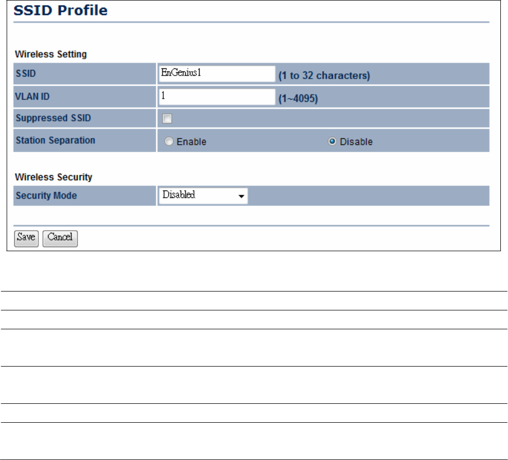
SSID
Specify
the
SSID
for the current
pro
f
il
e
.
VLAN ID
Specify
the
VLAN
tag for the current
pro
f
il
e
.
S
u
pp
r
e
ss
e
d
SSID
Check
this option to hide the
SSID
from
c
li
e
nt
s
.
If
c
he
c
k
e
d
,
t
he
SSID
will not appear in the site
s
ur
v
e
y
.
S
t
a
t
i
on
S
e
p
a
r
a
t
i
on
Click
the appropriate radio button to allow or
pr
e
v
e
nt
communication between client
de
v
i
ce
s
.
Wireless
S
ec
u
r
i
t
y
See
the
Wireless
S
ec
ur
i
t
y
section.
Save
/
C
a
n
ce
l
Click Save
to accept the
changes
or
C
a
n
ce
l
to
cancel
and
r
e
t
ur
n
previous
s
e
tt
i
ngs
.
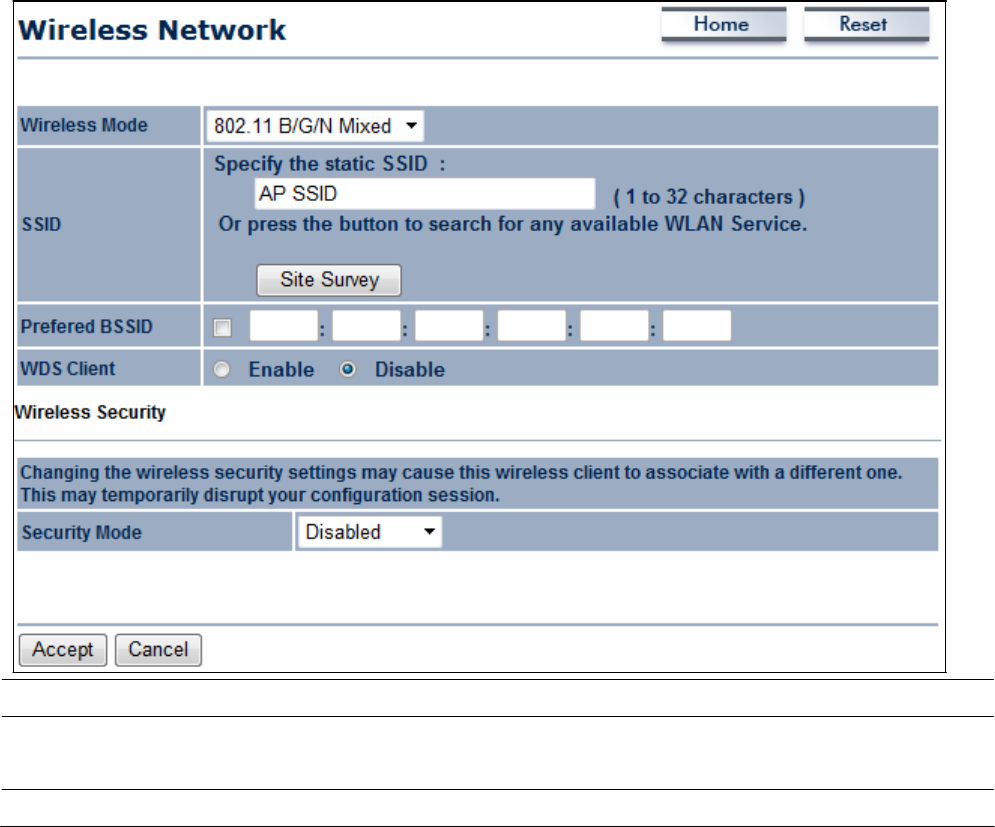
8.1.2
C
lie
n
t
Bridge
Mode
Client Bridge Mode lets you connect two LAN
segments
via a
wireless
link
as
though they are
on the
same physical
n
e
t
w
or
k
.
Since
the computers are on the
same
s
ubne
t
,
bro
a
dc
a
s
t
s
w
ill
reach all
m
ac
hi
ne
s
.
As a
r
e
s
ul
t
,
DHCP
information generated by the
server
will reach all
c
li
e
nt
computers
as
though the clients resided on one
physical
ne
t
w
or
k
.
The
following figure
shows
an example of an
OM2P V2
communicating with an Access
P
oi
nt
/
W
i
r
e
l
e
ss
R
out
e
r
,
such
as
the
E
n
G
e
ni
us
E
OA7530
,
operating in Client Bridge
M
ode
.
The
s
ec
t
i
ons
that follow the figure below describe how to configure your
OM2P V2
for Client
Bridge
M
ode
.
Wireless Mode
Wireless
mode supports
802
.
11
b/g/
n mixed
m
ode
s
.
SSID
Specify
the
SSID
if known.
This
field is completed automatically
i
f
you
s
e
l
ec
t
an
Access
P
oi
nt
in the Site
Sur
v
e
y
.
S
i
t
e
S
u
r
v
e
y
Scans
nearby locations for
Access
P
oi
nt
s
.
You
can
s
e
l
ec
t
a
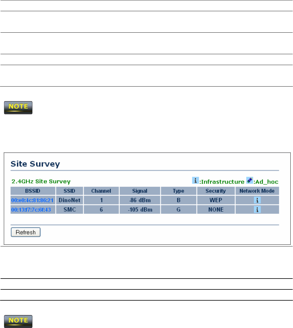
discovered
Access
P
oi
nt
to
e
s
t
a
bl
i
s
h a
c
onne
c
t
i
on.
Pr
e
f
e
r
BSSID
E
nt
e
r
the MAC
address
if known. If you select an
Access
P
oi
nt
i
n
the Site
Survey,
this field is completed
a
ut
om
a
t
i
ca
ll
y
.
WDS
C
li
e
n
t
Click
the appropriate radio button to enable or disable
W
D
S
C
li
e
nt
.
Wireless
S
ec
u
r
i
t
y
See
section
8.2
for
i
nfor
m
a
t
i
on
.
A
cce
p
t
/
C
a
n
ce
l
Click
A
cce
p
t
to confirm the
changes
or
C
a
n
ce
l
to
cancel
and
return previous
s
e
tt
i
ngs
.
Clicking
A
cce
p
t
does not apply the
changes.
To apply
t
he
m
,
use
S
t
a
t
u
s
>
S
a
v
e
/
L
o
a
d
(see
section
4
.
1
)
.
Profile
If you used the Site
Survey,
the Web Configurator
shows
nearby
Access
P
oi
nt
s
.
To connect to an
Access
P
oi
nt
,
click the Access
Point’s
BSSI
D
.
Wireless
S
ec
u
r
i
t
y
See
the
Wireless
S
ec
ur
i
t
y
section.
R
e
f
r
e
s
h
Click
R
e
f
r
e
s
h
to
scan
again.
If the
Access
P
oi
nt
has
been configured to
suppress
its
SSID,
the
SSID
section will be
bl
a
nk
and must be completed
m
a
nua
ll
y
.
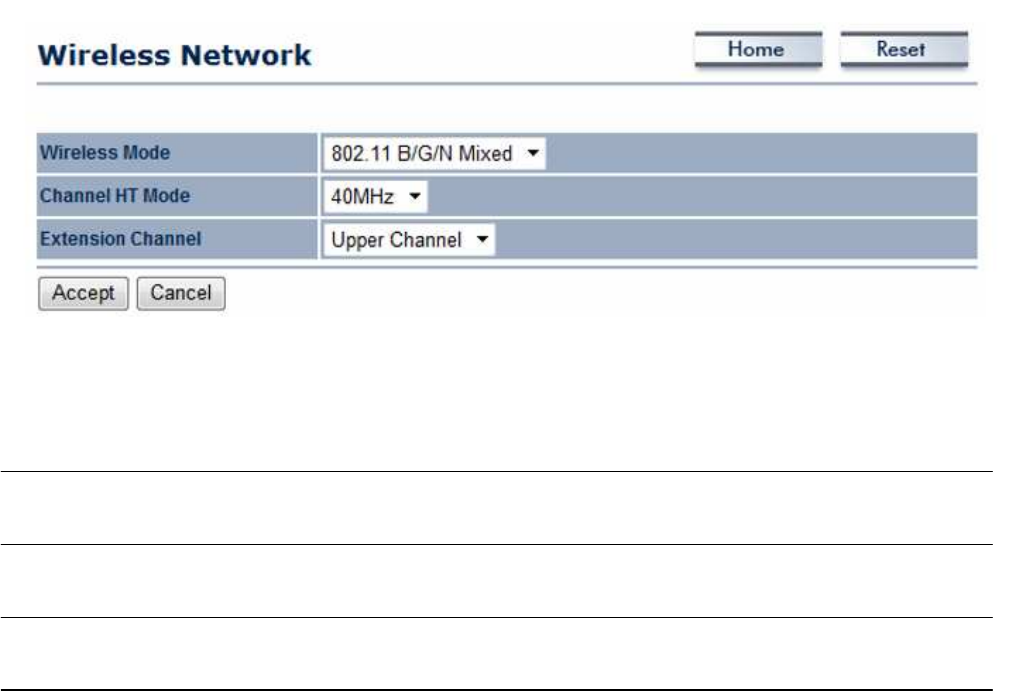
8.1.3 WDS Bridge
Mode
Unlike traditional bridging.
WDS
Bridge Mode allows you to create large
wireless
networks by
linking
several wireless access
points with
WDS
li
nk
s
.
WDS
is normally used in
l
a
r
ge
,
open
areas,
where pulling wires is cost
pr
ohi
bi
t
i
v
e
,
restricted or
physically
i
m
pos
s
i
bl
e
.
The
following figure
shows
an example of three
OM2P V2
configured for
WDS
Bridge
M
ode
communicating with
each
ot
he
r
.
In this configuration, the
OM2P V2
device on the left side of
t
he
figure
behaves as
a standard bridge that forwards traffic between the
WDS
links (links
t
ha
t
connect to other
OM2P V2 WDS
br
i
dge
s
)
.
The
s
ec
t
i
ons
that follow the figure below describe how to configure your
OM2P V2
for
W
D
S
Bridge
M
ode
.
Wireless Mode
Wireless
mode supports
802
.
11
b/g/
n mixed
m
ode
s
.
C
h
a
nn
e
l
HT Mode
The
default channel bandwidth is 40
M
Hz
.
The
larger the
c
ha
nne
l
,
the better the transmission quality and speed.
Extension
C
h
a
nn
e
l
Se
l
ec
t
upper or lower
c
ha
nne
l
.
Your
selection may affect the
Aut
o
channel
f
unc
t
i
on
.
A
cce
p
t
/
C
a
n
ce
l
Click
A
cce
p
t
to confirm the
changes
or
C
a
n
ce
l
to
cancel
and
return previous
s
e
tt
i
ngs
.
Clicking
A
cce
p
t
does not apply the
changes.
To apply
t
he
m
,
use
S
t
a
t
u
s
>
S
a
v
e
/
L
o
a
d
(see
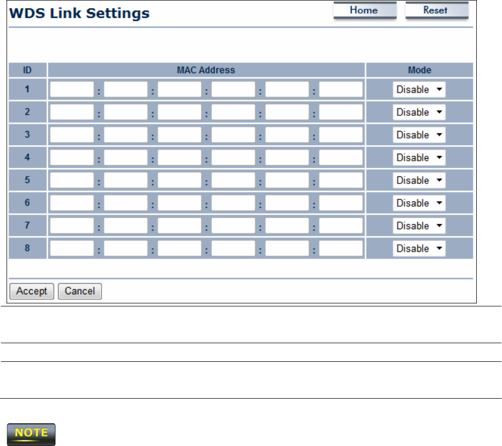
section
4
.
1
)
.
MAC Address
E
nt
e
r
the MAC
address
of the
Access
P
oi
nt
to which you want
t
o
extend
wireless
c
onne
c
t
i
v
i
t
y
.
Mode
Se
l
ec
t
Disable or
E
n
a
b
l
e
to disable or enable
W
D
S.
A
cce
p
t
/
C
a
n
ce
l
Click
A
cce
p
t
to confirm the
changes
or
C
a
n
ce
l
to
cancel
and
return previous
s
e
tt
i
ngs
.
1.
Clicking
A
cce
p
t
does not apply the
changes.
To apply
t
he
m
,
use
S
t
a
t
u
s
>
S
a
v
e
/
L
o
a
d
(see
section
4
.
1
)
.
2. The Access
P
oi
nt
to which you want to extend
wireless
connectivity must enter the
OM2P
V2
’
s
MAC
address
into its configuration.
For
more information, refer to the documentation for
t
he
Access
P
oi
nt
.
Not all
Access
P
oi
nt
supports this
f
ea
t
ur
e
.
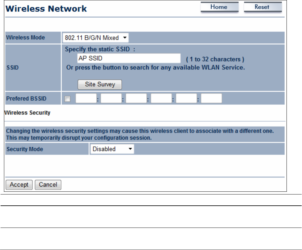
8.1.4
C
lie
n
t
R
o
u
t
e
r
Mode
In Client
Router
M
ode
,
you can
access
the Internet
wirelessly
with the support of a
WISP.
In AP
Router
M
ode
,
the
OM2P V2
can
access
the Internet via a cable or
DSL
m
ode
m
.
In this
m
ode
,
t
he
OM2P V2
can be configured to turn off the
wireless
network name
(SSID)
bro
a
dc
a
s
t
,
so
that
onl
y
stations that have the
SSID
can be
c
onne
c
t
e
d
.
The OM2P V2
also provides
wireless
LAN
64
/
128
/
152
-
bi
t
WEP
encryption
s
ec
ur
i
t
y
,
W
P
A/
W
P
A2
,
and
W
P
A
-
PSK
/
W
P
A2
-
PSK
a
ut
he
nti
ca
t
i
o
n,
as
well
as
TK
I
P
/
AE
S
encryption
s
ec
ur
i
t
y
.
It also supports
VPN
pass-through
f
or
s
ens
i
t
i
v
e
data
secure
t
r
ans
m
i
ss
i
on
.
The
following figure
shows
an
example
of an
OM2P V2
communicating with a
Wireless ISP
(
W
I
SP
) Access
P
oi
nt
in Client
Router
M
ode
.
The
s
ec
t
i
o
ns
that follow the figure below
describe
how
t
o
configure your
OM2P V2
for Client
Router
M
ode
.
Wireless Mode
Wireless
mode supports
802
.
11
b/g/
n mixed
m
ode
s
.
SSID
Specify
the
SSID
if known.
This
field is completed automatically
i
f
you
s
e
l
ec
t
an
Access
P
oi
nt
in the Site
Sur
v
e
y
.
S
i
t
e
S
u
r
v
e
y
Scans
nearby locations for
Access
P
oi
nt
s
.
You
can
s
e
l
ec
t
a
discovered
Access
P
oi
nt
to
e
s
t
a
bl
i
s
h a
c
onne
c
t
i
on.
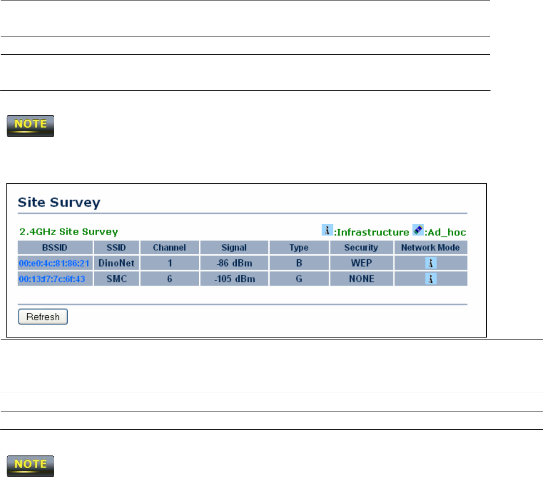
Pr
e
f
e
r
BSSID
E
nt
e
r
the MAC
address
if known. If you select an
Access
P
oi
nt
i
n
the Site
Survey,
this field is completed
a
ut
om
a
t
i
ca
ll
y
.
Wireless
S
ec
u
r
i
t
y
See
section
10
.
2
.
A
cce
p
t
/
C
a
n
ce
l
Click
A
cce
p
t
to confirm the
changes
or
C
a
n
ce
l
to
cancel
and
return previous
s
e
tt
i
ngs
.
Clicking
A
cce
p
t
does not apply the
changes.
To apply
t
he
m
,
use
S
t
a
t
u
s
>
S
a
v
e
/
L
o
a
d
(see
section
4
.
1
)
.
Profile
If you used the Site
Survey,
the Web Configurator
shows
nearby
Access
P
oi
nt
s
.
To connect to an
Access
P
oi
nt
,
click the Access
Point’s
BSSI
D
.
Wireless
S
ec
u
r
i
t
y
See
the
Wireless
S
ec
ur
i
t
y
section.
R
e
f
r
e
s
h
Click
R
e
f
r
e
s
h
to
scan
again.
If the
Access
P
oi
nt
has
been configured to
suppress
its
SSID,
the
SSID
section must be
completed
m
a
nua
ll
y
.
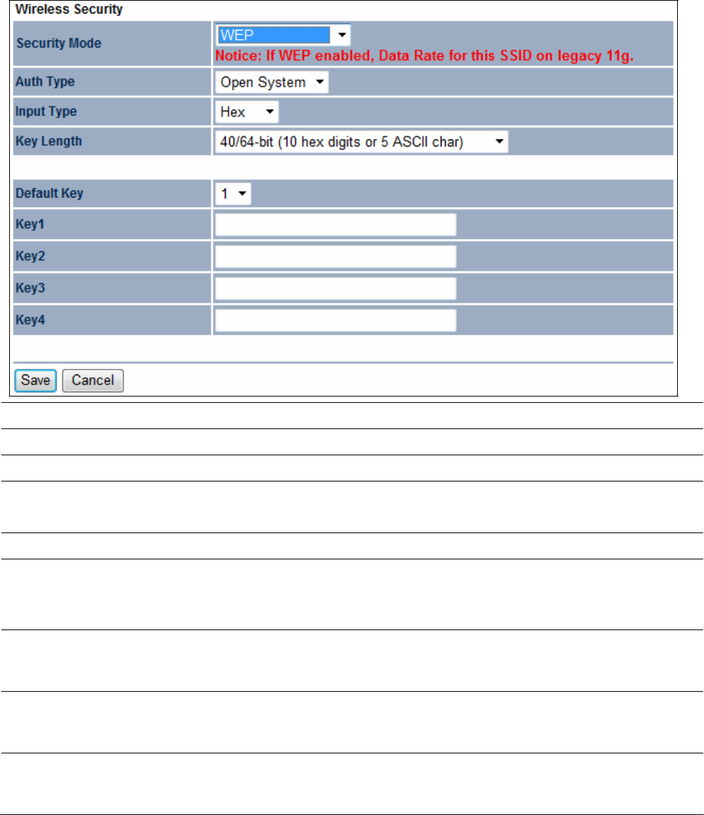
8.2
Wireless
Se
c
u
r
it
y
Se
tt
in
gs
The Wireless
Se
c
ur
i
t
y
S
e
tt
i
ngs
section lets you configure the
E
OH200
’
s
security
m
ode
s
:
W
E
P
,
W
P
A
-
PSK
,
W
P
A2
-
PSK
,
W
P
A
-
PSK
Mixed,
WPA, WPA2,
and
WPA
Mi
xe
d
.
We
s
t
rongl
y
recommend you
use
W
P
A2
-
PSK
.
8.2.1
W
E
P
S
ec
u
r
i
t
y
Mode
Se
l
ec
t
WEP
from the drop-down list to begin the
c
onf
i
gur
a
t
i
o
n.
A
u
t
h
Type
Se
l
ec
t
Open
S
y
s
t
e
m
or
S
h
a
r
e
d
.
Input
Type
Se
l
ec
t
an input type of Hex or
A
S
C
II
.
Key
L
e
n
g
t
h
Level
of
WEP
encryption applied to all
WEP keys. Choices
are
Se
l
ec
t
a
64
/
128
/
152
-
bi
t
password
l
e
ngt
h
s
.
D
e
f
a
u
l
t
Key
Specify
which of the four
WEP keys
the
OM2P V2 uses as
its
de
f
a
ul
t
.
Key1
Specify
a
password
for security key index
N
o.1
.
For
s
ec
ur
i
t
y
,
each
typed
c
ha
r
ac
t
e
r
is
masked
by a dot
(
l
)
.
Key2
Specify
a
password
for security key index
N
o.2
.
For
s
ec
ur
i
t
y
,
each
typed
c
ha
r
ac
t
e
r
is
masked
by a dot
(
l
)
.
Key3
Specify
a
password
for security key index
N
o.3
.
For
s
ec
ur
i
t
y
,
each
typed
c
ha
r
ac
t
e
r
is
masked
by a dot
(
l
)
.
Key4
Specify
a
password
for security key index
N
o.4
.
For
s
ec
ur
i
t
y
,
each
typed
c
ha
r
ac
t
e
r
is
masked
by a dot
(
l
)
.
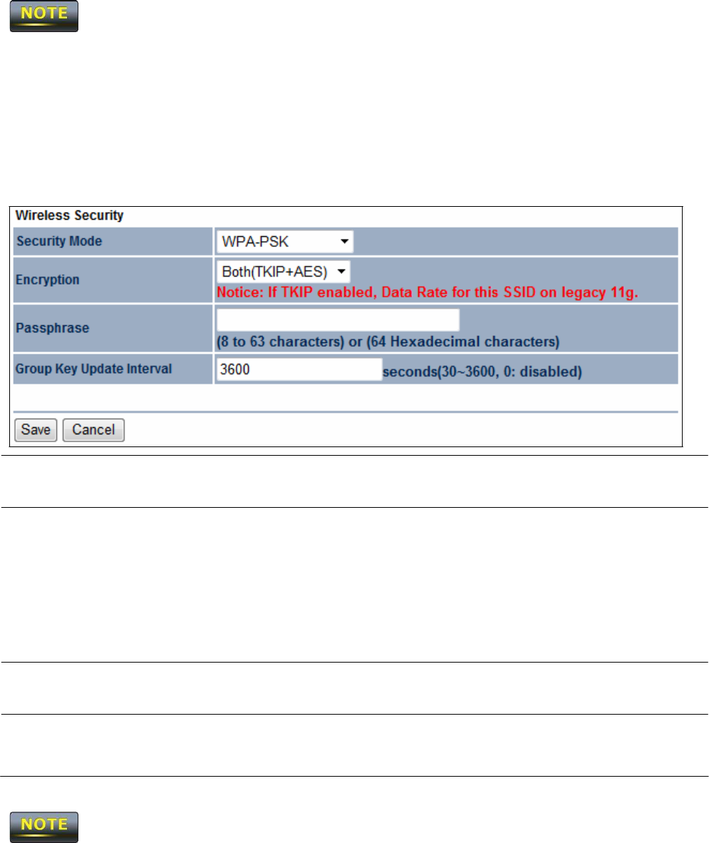
802
.
11
n does not allow
W
E
P
/
W
P
A
-
PSK
/
W
P
A
-
PSK
TKIP
security
m
ode
.
The
connection
m
ode
will drop from
802
.
11
n to
802
.
11g.
8.2.2 WPA-PSK
S
ec
u
r
i
t
y
Mode
Se
l
ec
t
WPA-PSK
from the drop-down list to begin
t
he
c
onf
i
gur
a
t
i
o
n.
En
c
r
y
p
t
i
on
Se
l
ec
t
B
ot
h
,
TKI
P
,
or
AES as
the encryption
t
y
pe
.
• Both =
uses TKIP
and
AE
S.
•
TKIP
= automatic encryption with
W
P
A
-
PSK
;
requires
p
a
ss
phr
a
s
e
.
•
AES
= automatic encryption with
W
P
A2
-
PSK
;
requires
p
a
ss
phr
a
s
e
.
Passphrase
Specify
the security
password. For
s
ec
ur
i
t
y
,
each
typed character
is
masked
by a dot
(
l
)
.
Group Key
U
pd
a
t
e
I
n
t
e
r
v
a
l
Specify
how often, in
seconds,
the group key
c
ha
nge
s
.
802
.
11
n does not allow
W
E
P
/
W
P
A
-
PSK
/
W
P
A
-
PSK
TKIP
security
m
ode
.
The
connection
m
ode
will drops from
802
.
11
n to
802
.
11g.
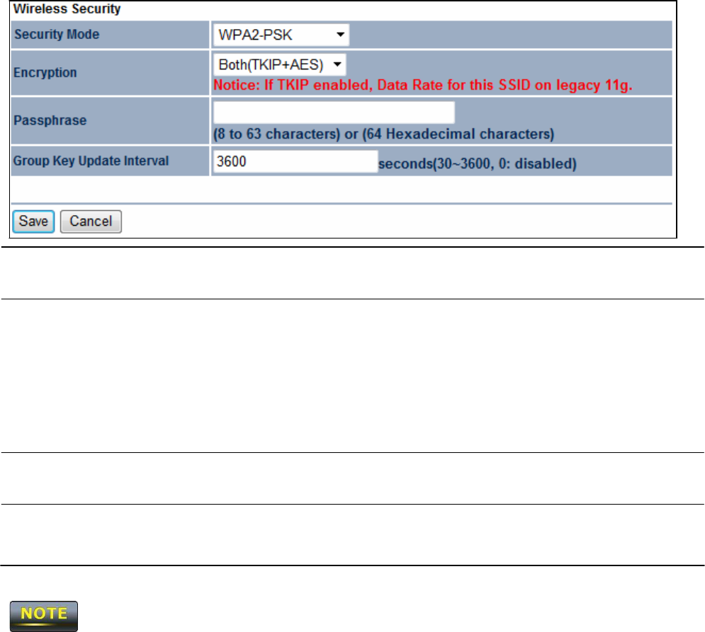
8.2.3
W
P
A2
-
P
SK
S
ec
u
r
i
t
y
Mode
Se
l
ec
t
WPA2-PSK from the drop-down list to begin
t
he
c
onf
i
gur
a
t
i
o
n.
En
c
r
y
p
t
i
on
Se
l
ec
t
B
ot
h
,
TKI
P
,
or
AES as
the encryption
t
y
pe
.
• Both =
uses TKIP
and
AE
S.
•
TKIP
= automatic encryption with
W
P
A
-
PSK
;
requires
p
a
ss
phr
a
s
e
.
•
AES
= automatic encryption with
W
P
A2
-
PSK
;
requires
p
a
ss
phr
a
s
e
.
Passphrase
Specify
the security
password. For
s
ec
ur
i
t
y
,
each
typed character
is
masked
by a dot
(
l
)
.
Group Key
U
pd
a
t
e
I
n
t
e
r
v
a
l
Specify
how often, in
seconds,
the group key
c
ha
nge
s
.
802
.
11
n does not allow
W
E
P
/
W
P
A
-
PSK
/
W
P
A
-
PSK
TKIP
security
m
ode
.
The
connection
m
ode
will change from
802
.
11
n to
802
.
11g.
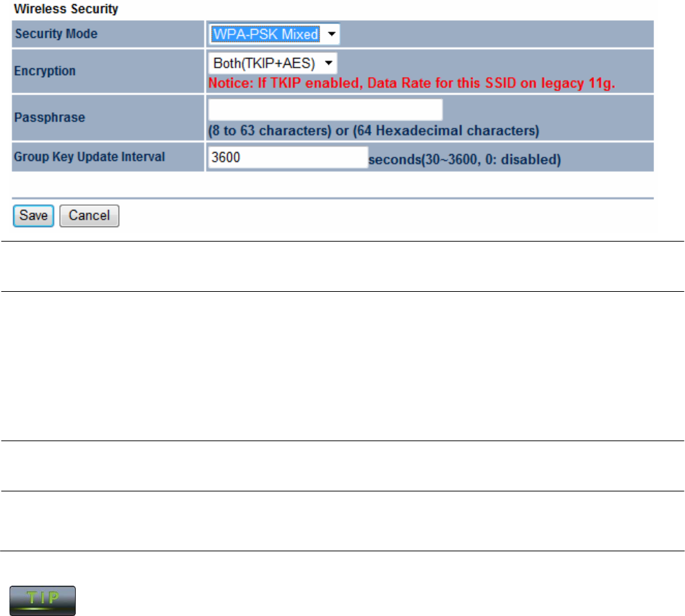
8.2.4
W
P
A
-
P
SK
M
i
x
e
d
S
ec
u
r
i
t
y
Mode
Se
l
ec
t
WPA-PSK
Mixed
from the drop-down list to begin
t
he
c
onf
i
gur
a
t
i
o
n.
En
c
r
y
p
t
i
on
Se
l
ec
t
B
ot
h
,
TKI
P
,
or
AES as
the encryption
t
y
pe
.
• Both =
uses TKIP
and
AE
S.
•
TKIP
= automatic encryption with
W
P
A
-
PSK
;
requires
p
a
ss
phr
a
s
e
.
•
AES
= automatic encryption with
W
P
A2
-
PSK
;
requires
p
a
ss
phr
a
s
e
.
Passphrase
Specify
the security
password. For
s
ec
ur
i
t
y
,
each
typed character
is
masked
by a dot
(
l
)
.
Group Key
U
pd
a
t
e
I
n
t
e
r
v
a
l
Specify
how often, in
seconds,
the group key
c
ha
nge
s
.
W
P
A
-
PSK
Mixed can allow multiple security modes at the
same
t
i
m
e
.
802
.
11
n does not allow
W
E
P
/
W
P
A
-
PSK
/
W
P
A
-
PSK
TKIP
security
m
ode
.
The
connection
m
ode
will change from
802
.
11
n to
802
.
11g.
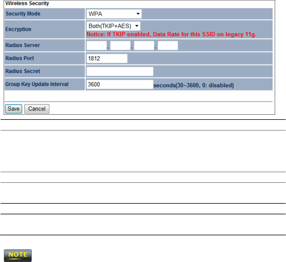
8.2.5
W
P
A
S
ec
u
r
i
t
y
Mode
Se
l
ec
t
WPA from the drop-down list to begin the
c
onf
i
gur
a
t
i
o
n.
En
c
r
y
p
t
i
on
Se
l
ec
t
B
ot
h
,
TKI
P
,
or
AES as
the encryption
t
y
pe
.
• Both =
uses TKIP
and
AE
S.
•
TKIP
= automatic encryption with
W
P
A
-
PSK
.
•
AES
= automatic encryption with
W
P
A2
-
PSK
.
Ra
d
i
u
s
S
e
r
v
e
r
Specify
the
IP address
of the
RADIUS
s
e
r
v
e
r
.
Ra
d
i
u
s
P
or
t
Specify
the port number that your
RADIUS server uses
f
or
authentication. Default port is
1812
.
Ra
d
i
u
s
S
ec
r
e
t
Specify RADIUS
s
ec
r
e
t
furnished by the
RADIUS
s
e
r
v
e
r
.
Group Key
U
pd
a
t
e
I
n
t
e
r
v
a
l
Specify
how often, in
seconds,
the group key
c
ha
nge
s
.
802
.
11
n does not allow
W
E
P
/
W
P
A
-
PSK
/
W
P
A
-
PSK
TKIP
security
m
ode
.
The
connection
m
ode
will drops from
802
.
11
n to
802
.
11g.
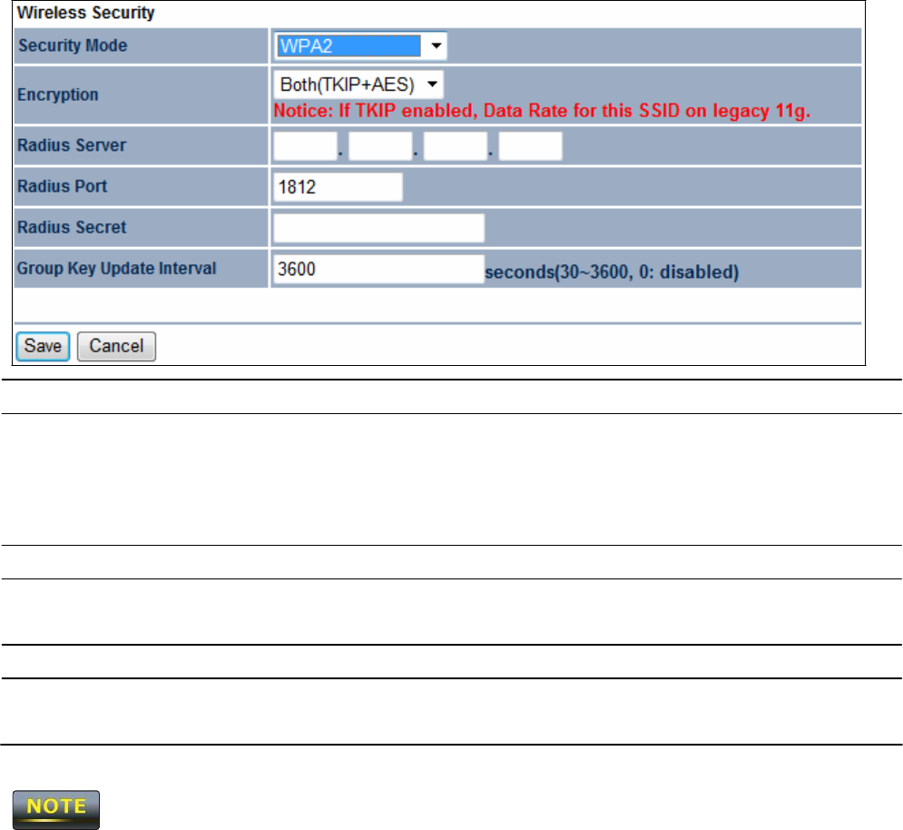
8.2.6
W
P
A
2
S
ec
u
r
i
t
y
Mode
Se
l
ec
t
WPA2 from the drop-down list to begin the
c
onf
i
gur
a
t
i
o
n.
En
c
r
y
p
t
i
on
Se
l
ec
t
B
ot
h
,
TKI
P
,
or
AES as
the encryption
t
y
pe
.
• Both =
uses TKIP
and
AE
S.
•
TKIP
= automatic encryption with
W
P
A
-
PSK
.
•
AES
= automatic encryption with
W
P
A2
-
PSK
.
Ra
d
i
u
s
S
e
r
v
e
r
Specify
the
IP address
of the
RADIUS
s
e
r
v
e
r
.
Ra
d
i
u
s
P
or
t
Specify
the port number that your
RADIUS server uses
f
or
authentication. Default port is
1812
.
Ra
d
i
u
s
S
ec
r
e
t
Specify RADIUS
s
ec
r
e
t
furnished by the
RADIUS
s
e
r
v
e
r
.
Group Key
U
pd
a
t
e
I
n
t
e
r
v
a
l
Specify
how often, in
seconds,
the group key
c
ha
nge
s
.
802
.
11
n does not allow
W
E
P
/
W
P
A
-
PSK
/
W
P
A
-
PSK
TKIP
security
m
ode
.
The
date rate will
drop
from
802
.
11
n to
802
.
11g.
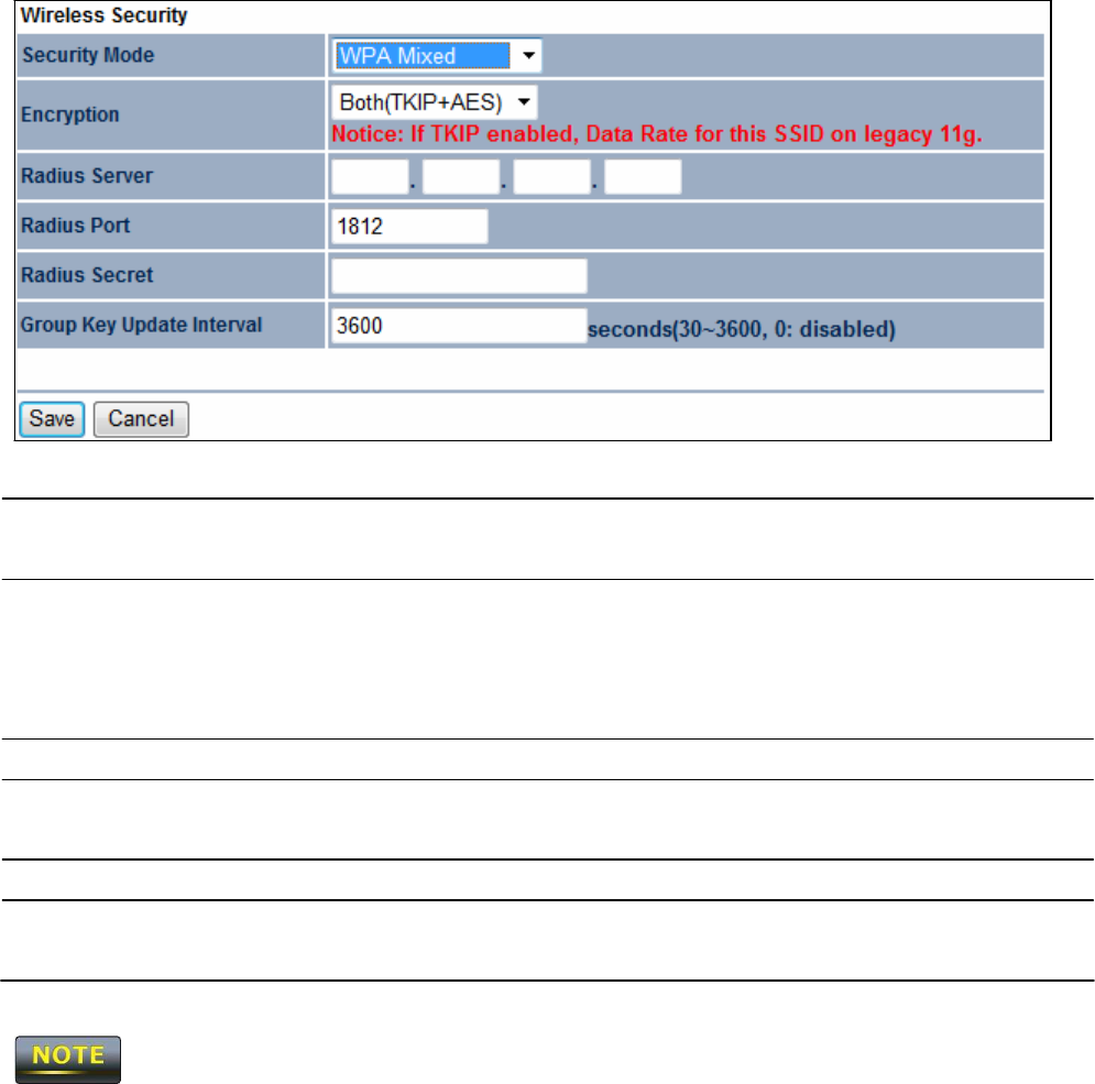
8.2.7
W
P
A
M
i
x
e
d
S
ec
u
r
i
t
y
Mode
Se
l
ec
t
WPA
Mixed
from the drop-down list to begin
t
he
c
onf
i
gur
a
t
i
o
n.
En
c
r
y
p
t
i
on
Se
l
ec
t
B
ot
h
,
TKI
P
,
or
AES as
the encryption
t
y
pe
.
• Both =
uses TKIP
and
AE
S.
•
TKIP
= automatic encryption with
W
P
A
-
PSK
.
•
AES
= automatic encryption with
W
P
A2
-
PSK
.
Ra
d
i
u
s
S
e
r
v
e
r
Specify
the
IP address
of the
RADIUS
s
e
r
v
e
r
.
Ra
d
i
u
s
P
or
t
Specify
the port number that your
RADIUS server uses
f
or
authentication. Default port is
1812
.
Ra
d
i
u
s
S
ec
r
e
t
Specify RADIUS
s
ec
r
e
t
furnished by the
RADIUS
s
e
r
v
e
r
.
Group Key
U
pd
a
t
e
I
n
t
e
r
v
a
l
Specify
how often, in
seconds,
the group key
c
ha
nge
s
.
802
.
11
n does not allow
W
E
P
/
W
P
A
-
PSK
/
W
P
A
-
PSK
TKIP
security
m
ode
.
The
connection
m
ode
will change from
802
.
11
n to
802
.
11g.
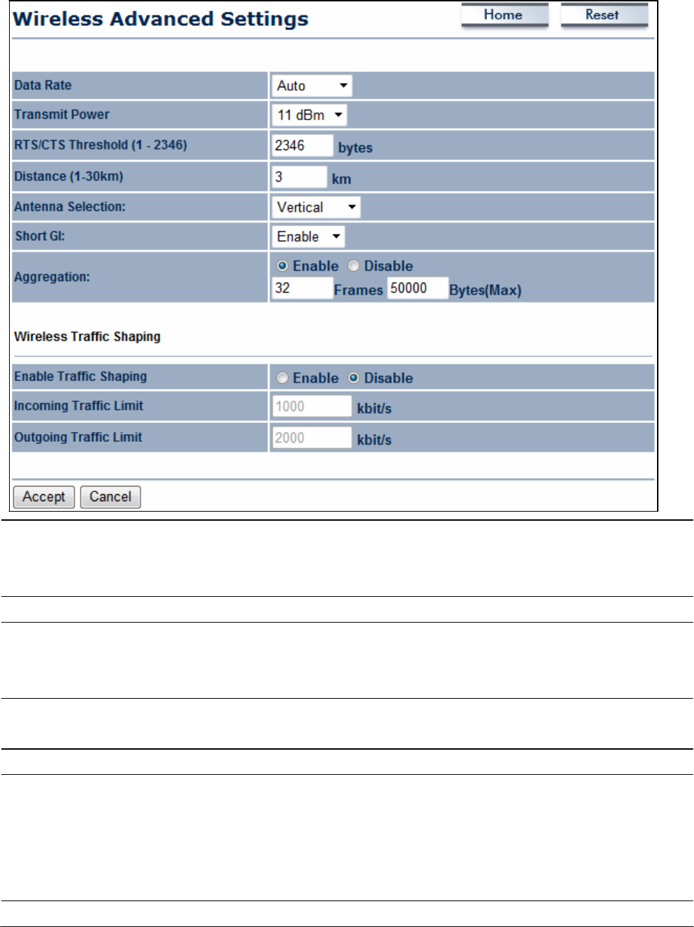
8.4
W
i
reless
Ad
v
a
nced
Se
t
t
i
n
gs
D
a
t
a
Ra
t
e
Se
l
ec
t
a data rate from the drop-down
li
s
t
.
The
data rate affects
t
hr
o
ugh
put
.
If you
s
e
l
ec
t
a low data rate
v
a
l
ue
,
for
exa
m
pl
e
,
t
he
throughput is reduced but the transmission distance
i
nc
r
ea
s
e
s
.
R
T
S
/
C
T
S
Threshold
Specify
the threshold
package size
for
R
TC
/
CT
S.
A small num
be
r
causes RTS/CTS
p
ac
k
e
t
s
to be sent more often and consumes
more
b
a
ndw
i
d
t
h
.
D
i
s
t
a
n
ce
Specify
the distance between
Access Points
and
c
li
e
nt
s
.
Longer
di
s
t
a
nc
e
s
may drop high-speed
c
onne
c
t
i
ons
.
A
n
t
e
nn
a
S
e
l
ec
t
i
on
Specify
the internal antenna
t
y
pe
.
S
h
or
t
GI
Se
t
s
the time that the
receiver
waits for
RF
reflections to settle
out
before sampling
da
t
a
.
Using a short
(400ns)
guard interval can
increase
t
hrough
put
,
but can also
increase
error rate in some
installations due to
increased
sensitivity to radio-frequency
r
e
f
l
ec
t
i
ons
.
Se
l
ec
t
the option that works best for your
i
ns
t
a
ll
a
t
i
on
.
A
gg
r
e
g
a
t
i
on
Merges data
p
ac
k
e
t
s
into one
p
ac
k
e
t
.
This
option
reduces
t
he

Wireless
T
r
a
ff
i
c
S
h
a
p
i
n
g
number of
p
ac
k
e
t
s
,
but
increases
packet
s
i
z
e
s
.
Check
this option to enable
wireless
t
r
a
ff
ic
s
ha
pi
ng
.
Traffic
shaping regulates the flow of
p
ac
k
e
t
s
leaving an interface
t
o
deliver improved Quality of
S
e
r
v
i
ce
.
Incoming Traffic
L
i
m
i
t
Specify
the
wireless
transmission speed used for
downl
o
a
di
ng.
O
u
t
g
oi
n
g
Traffic
L
i
m
i
t
Specify
the
wireless
transmission speed used for
upl
o
a
di
ng.
A
cce
p
t
/
C
a
n
ce
l
Click
A
cce
p
t
to confirm the
changes
or
C
a
n
ce
l
to
cancel
and
return previous
s
e
tt
i
ngs
.
1.
Changing
Wireless
Advanced Settings may
adversely
affect
wireless
pe
r
f
or
m
a
nc
e
.
P
l
ea
s
e
accept all default
s
e
tt
i
ngs
,
unless
you are familiar with the
wireless
op
t
i
ons
.
2.
Clicking
A
cce
p
t
does not apply the
changes.
To apply
t
he
m
,
use
S
t
a
t
u
s
>
S
a
v
e
/
L
o
a
d
(see
section
4
.
1
)
.
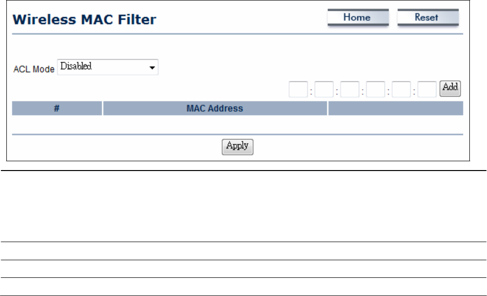
8.5
W
i
reless
M
A
C
F
ilt
e
r
Wireless
MAC
F
il
t
e
r
s
are used to allow or deny network
access
to
wireless
clients according
t
o
their MAC
addresses. You
can manually add a MAC
address
to restrict the permission
t
o
access
OM2P V2
.
The
default setting is
Disable Wireless
MAC
F
il
t
e
r
s
.
0.
ACL
Mode Determines whether network
access
is granted or denied
t
o
clients whose MAC
addresses
appear in the MAC Address
t
a
bl
e
on this
p
a
ge
.
Choices
are D
i
s
a
b
l
e
,
Deny MAC
in
t
h
e
li
s
t
,
or
Allow
MAC
in
t
h
e
li
s
t
.
MAC Address
F
il
t
e
r
E
nt
e
r
the MAC
address
of the
de
v
i
ce
.
Add
Click
Add to add the MAC
address
to the MAC Address
t
a
bl
e
.
Apply
Click
Apply
to apply the
c
ha
nge
s
.
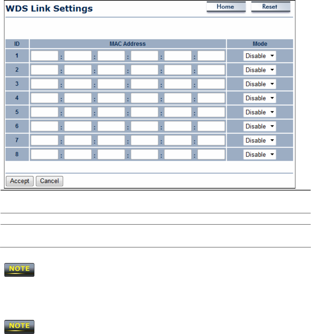
8.6
WDS
L
i
nk
Se
tt
i
n
gs
Using
WDS
Link
Se
tt
i
n
gs
,
you can create a
wireless
backbone link between multiple access
points that are part of the
same wireless
ne
t
w
or
k
.
This
allows a
wireless
network to be
expanded using multiple
Access Points
without the need for a wired backbone to link
t
he
m
,
as
is traditionally required.
MAC Address
E
nt
e
r
the
Access Point’s
MAC
address
to which you want
t
o
extend the
wireless
a
r
ea
.
Mode
Se
l
ec
t
Disable or
E
n
a
b
l
e
from the drop-down
li
s
t
.
A
cce
p
t
/
C
a
n
ce
l
Click
A
cce
p
t
to confirm the
changes
or
C
a
n
ce
l
to
cancel
and
return previous
s
e
tt
i
ngs
.
Clicking
A
cce
p
t
does not apply the
changes.
To apply
t
he
m
,
use
S
t
a
t
u
s
>
S
a
v
e
/
L
o
a
d
(see
section
4
.
1
)
.
The Access
P
oi
nt
to which you want to extend
wireless
connectivity must enter the
OM2P V2
’
s
MAC
address
into its configuration.
For
more information, refer to the documentation for
t
he
Access
P
oi
nt
.
Not all
Access
P
oi
nt
supports this
f
ea
t
ur
e
.
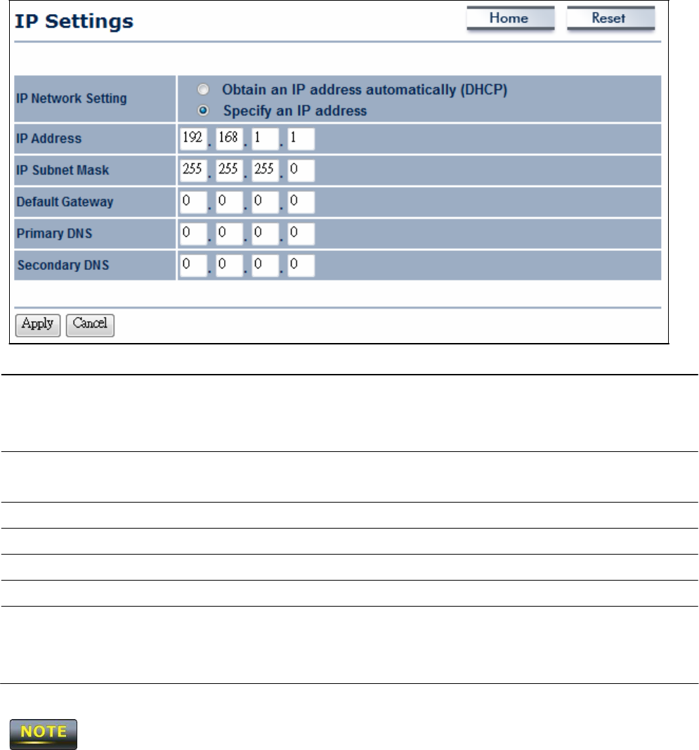
C
ha
p
t
e
r
9
LAN
Se
t
u
p
This
chapter
describes
the
OM2P V2 Local
Area Network
(LAN)
s
e
tt
i
ngs
.
9.1 IP
Se
tt
in
gs
This
section is only
available
for
Non
-
R
ou
t
e
r
M
od
e
.
IP
settings lets you configure the
OM2P
V2
LAN port
IP
a
ddr
e
ss
.
IP
N
e
t
w
ork
S
e
tt
i
n
g
Se
l
ec
t
whether the
OM2P V2 IP address
will
use
the static
IP
address s
pe
c
i
f
ied in the IP Address field or be obtained
a
ut
om
a
t
i
ca
ll
y
when the
OM2P V2
connects to a device that
has
a
DHCP server .
IP Address
E
nt
e
r
the
IP address
of the
OM2P
V2
.
IP
S
u
e
t
Mask
E
nt
e
r
the
OM2P V2
subnet
m
a
s
k
.
D
e
f
a
u
l
t
G
a
t
e
w
a
y
E
nt
e
r
the
OM2P V2
default
ga
t
e
w
a
y
.
Primary
DNS
E
nt
e
r
the
OM2P V2
primary
D
N
S.
S
ec
on
d
a
r
y
DNS
E
nt
e
r
the
OM2P V2 secondary
D
N
S.
A
cce
p
t
/
C
a
n
ce
l
Click
A
cce
p
t
to confirm the
changes
or
C
a
n
ce
l
to
cancel
and
return previous
s
e
tt
i
ngs
.
If you change the LAN
IP address,
you will be directed to the new
IP address
after you click
A
pp
l
y
.
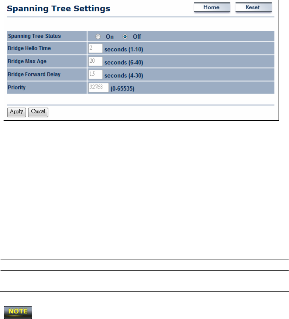
9.2
S
p
ann
i
ng
T
ree
Se
tt
in
gs
S
p
a
nn
i
n
g
Tree
S
t
a
t
u
s
E
na
bl
e
or disable the
OM2P V2
Spanning
Tree
f
u
nc
t
i
on
.
Bridge Hello Time
Specify
Bridge Hello
Time,
in
seconds. This
value determine how
often the
OM2P V2 sends
hello
p
ac
k
e
t
s
to communicate
i
nfor
m
a
t
i
on
about the topology throughout the entire Bridged
Local
Area
N
e
t
w
or
k
Bridge
Max Age
Specify
Bridge Max Ag
e
,
in
seconds.
If another bridge in
t
he
spanning tree does not send a hello packet for a long period
o
f
t
i
m
e
,
it is
assumed
to be dead.
Bridge
Forward
Delay
Specify
Bridge
F
or
w
a
rd
Delay,
in
seconds.
F
or
w
a
rdi
ng
delay
t
i
m
e
is the time spent in
each
of the Listening and Learning states
before the
F
or
w
a
rdi
ng
state is entered.
This
delay is provided so
that when a new bridge comes onto a busy n
e
t
w
or
k
,
it looks
a
t
some traffic before
p
a
r
t
i
c
i
p
a
t
i
ng.
Priority
Specify
the
P
r
i
or
i
t
y
num
be
r
.
Smaller
number
has
greater
pr
i
or
i
t
y
.
A
cce
p
t
/
C
a
n
ce
l
Click
A
cce
p
t
to confirm the
changes
or
C
a
n
ce
l
to
cancel
and
return previous
s
e
tt
i
ngs
.
Clicking
A
cce
p
t
does not apply the
changes.
To apply
t
he
m
,
use
S
t
a
t
u
s
>
S
a
v
e
/
L
o
a
d
(see
section
4
.
1
)
.
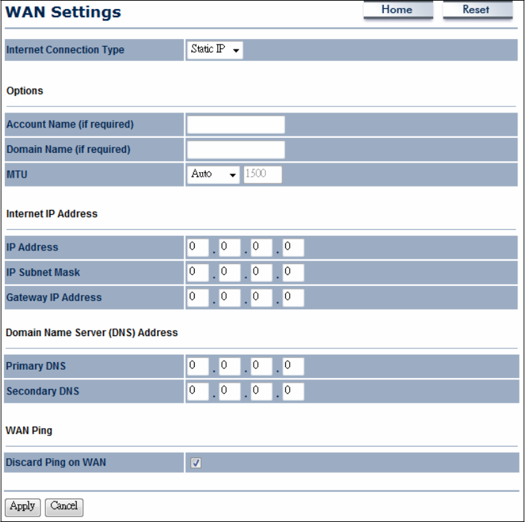
C
ha
p
t
e
r
10
R
ou
t
e
r
Se
tt
i
n
gs
This
section is only
available
for AP
R
ou
t
e
r
Mode and
C
li
e
n
t
R
ou
t
e
r
M
od
e
.
10.1 WAN
Se
tt
in
g
s
This
chapter
describes
the
OM2P V2
WAN
s
e
tt
i
n
gs
.
There
are four types of WAN
c
onne
c
t
i
on
s
:
-
S
t
a
t
i
c
I
P
-
D
HC
P
-
PPP
oE
-
PP
T
P
Please
contact your
ISP
to find out which settings you should
c
hoos
e
..
10.1.1
S
t
a
t
ic
IP
Se
l
ec
t
S
t
a
t
i
c
IP for your WAN connection if your
ISP
provided information about which
I
P
address,
subnet
mask,
default
ga
t
e
w
a
y
,
primary
DNS,
and
secondary DNS
to
use
.

I
n
t
e
r
n
e
t
C
onn
ec
t
i
on
T
y
p
e
Se
l
ec
t
S
t
a
t
i
c
IP to begin configuration of the
S
t
a
t
i
c
IP
c
onne
c
t
i
on.
A
cc
oun
t
Name
E
nt
e
r
the account name provided by your
I
S
P
.
Domain
Name
E
nt
e
r
the domain name provided by your
I
S
P
.
MTU
Specify
the Maximum Transmit Unit
size.
It is recommended
y
ou
accept the default setting of
A
u
t
o
.
O
t
he
r
w
i
s
e
,
p
ac
k
e
t
s
will be
fragmented downstream if the MTU is set too high or too
l
ow
,
which impacts network
pe
r
f
or
m
a
nc
e
.
In extreme
cases,
an MTU
setting that is too low can prevent the
OM2P V2
from
establishing some
c
onne
c
t
i
ons
.
IP Address
E
nt
e
r
the WAN port
IP address.
IP
S
u
b
n
e
t
Mask
E
nt
e
r
the WAN
IP
subnet
m
a
s
k
.
G
a
t
e
w
a
y
IP Address
E
nt
e
r
the WAN gateway
IP
a
ddr
e
ss
.
Primary
DNS
E
nt
e
r
the primary
DNS IP
a
ddr
e
ss
.
S
ec
on
d
a
r
y
DNS
E
nt
e
r
the
secondary DNS IP a
ddr
e
ss
.
Discard
Ping on WAN
Check
to
En
a
b
l
e
to recognize pings on the
OM2P V2
WAN
interface or Disable to block pings on the
OM2P V2
WAN
int
e
r
f
ace
.
N
ot
e
:
P
i
nging
IP addresses
is a common method used
by
hackers
t
o
test whether the
IP address
is valid. Blocking pings provides some
extra security from
ha
c
k
e
r
s
.
A
cce
p
t
/
C
a
n
ce
l
Click
A
cce
p
t
to confirm the
changes
or
C
a
n
ce
l
to
cancel
and
return previous
s
e
tt
i
ngs
.
Clicking
A
cce
p
t
does not apply the
changes.
To apply
t
he
m
,
use
S
t
a
t
u
s
>
S
a
v
e
/
L
o
a
d
(see
section
4
.
1
)
.
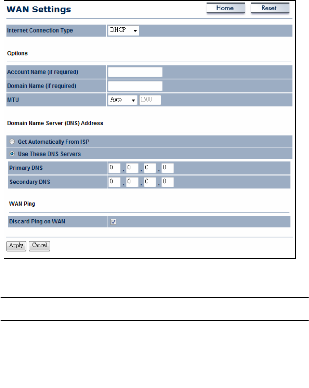
10.1.2 DHCP (Dynamic
IP)
Se
l
ec
t
DHCP as
your WAN connection type to obtain an
IP address a
ut
om
a
t
i
ca
ll
y
.
You
w
ill
need to enter account name
as
your hostname
a
nd
,
op
t
i
ona
ll
y
,
DNS
i
nfor
m
a
t
i
on
.
I
n
t
e
r
n
e
t
C
onn
ec
t
i
on
T
y
p
e
Se
l
ec
t
DHCP
to begin configuration of the
DHCP
c
onne
c
t
i
on.
A
cc
oun
t
Name
E
nt
e
r
the account name provided by your
I
S
P
.
Domain
Name
E
nt
e
r
the domain name provided by your
I
S
P
.
MTU
Specify
the Maximum Transmit Unit
size.
It is recommended
y
ou
accept the default setting of
A
u
t
o
.
O
t
he
r
w
i
s
e
,
p
ac
k
e
t
s
will be
fragmented downstream if the MTU is set too high or too
l
ow
,
which impacts network
pe
r
f
or
m
a
nc
e
.
In extreme
cases,
an MTU
setting that is too low can prevent the
OM2P V2
from
establishing some
c
onne
c
t
i
ons
.

G
e
t
A
u
t
om
a
t
i
ca
ll
y
From
I
S
P
Click
this radio button to obtain the
DNS
automatically from
t
he
DHCP
s
e
r
v
e
r
.
Use These
DNS Servers
Click
the radio button to set up the
Primary DNS
and Secondary
DNS servers
m
a
nu
a
ll
y
.
Discard
Ping on WAN
Check
to
En
a
b
l
e
to recognize pings on the
OM2P V2
WAN
interface or Disable to block pings on the
OM2P V2
WAN
int
e
r
f
ace
.
N
ot
e
:
P
i
nging
IP addresses
is a common method used
by
hackers
t
o
test whether the
IP address
is valid. Blocking pings provides some
extra security from
ha
c
k
e
r
s
.
A
cce
p
t
/
C
a
n
ce
l
Click
A
cce
p
t
to confirm the
changes
or
C
a
n
ce
l
to
cancel
and
return previous
s
e
tt
i
ngs
.
Clicking
A
cce
p
t
does not apply the
changes.
To apply
t
he
m
,
use
S
t
a
t
u
s
>
S
a
v
e
/
L
o
a
d
(see
section
4
.
1
)
.
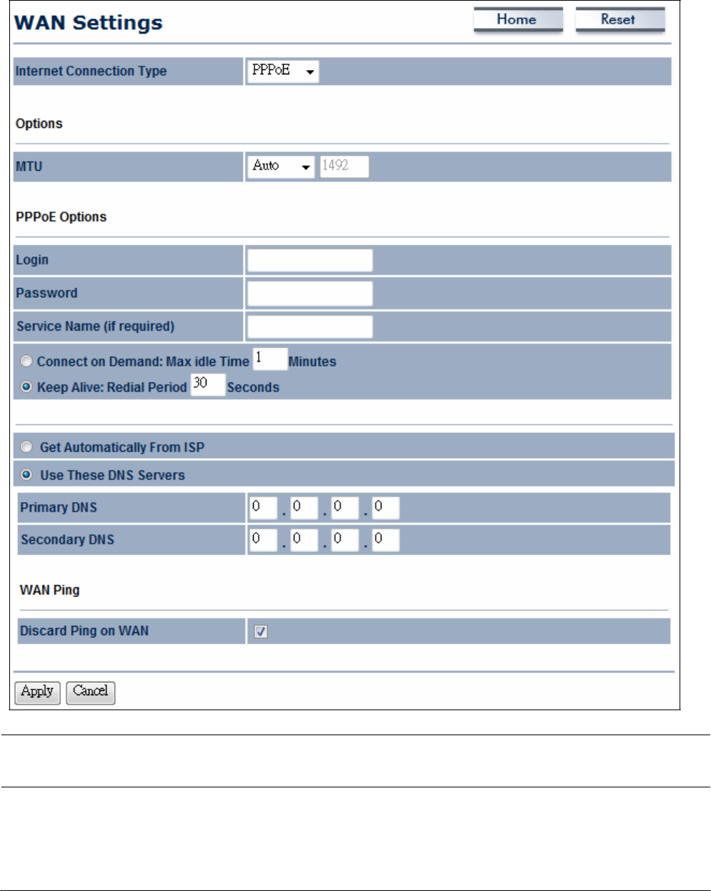
10.1.3
PPPoE
(
P
oi
n
t
-
t
o
-
P
oin
t
P
r
o
t
oc
ol
over
E
t
he
r
n
e
t
)
Se
l
ec
t
P
oi
nt
to
P
oi
nt
P
r
ot
oc
ol
over
E
t
he
r
ne
t
(PPPoE)
if
your
ISP uses
a
PPPoE
c
onne
c
t
i
on.
Your ISP
will provide you with a
username
and
password. This
selection is typically used
f
or
DSL services. Remove
your
PPPoE
software from your
c
om
put
e
r
,
as
it is not needed and
w
ill
not work with your
OM2P
V2
.
I
n
t
e
r
n
e
t
C
onn
ec
t
i
on
T
y
p
e
Se
l
ec
t
PPPoE
to begin configuration of the
PPPoE
c
onne
c
t
i
on
.
MTU
Specify
the Maximum Transmit Unit
size.
It is recommended
y
ou
accept the default setting of
A
u
t
o
.
O
t
he
r
w
i
s
e
,
p
ac
k
e
t
s
will be
fragmented downstream if the MTU is set too high or too
l
ow
,
which impacts network
pe
r
f
or
m
a
nc
e
.
In extreme
cases,
an MTU

setting that is too low can prevent the
OM2P V2
from
establishing some
c
onne
c
t
i
ons
.
Login
E
nt
e
r
the Username provided by your
I
S
P
.
Password
E
nt
e
r
the Password provided by your
I
S
P
.
S
e
r
v
i
ce
Name
E
nt
e
r
the
S
e
r
v
i
ce
Name provided by your
I
S
P
.
C
onn
ec
t
on Demand
Se
l
ec
t
the radio button to specify the maximum idle
t
i
m
e
.
Internet connection will disconnect when it reach the
m
ax
i
m
um
idle
t
i
m
e
,
but it will automatically connect when user tries
t
o
access
the
ne
t
w
or
k
.
Keep
Alive
Se
l
ec
t
whether to keep the Internet connection
always
on
,
or
enter a redial period once the internet lose
c
onne
c
t
i
on
.
G
e
t
A
u
t
om
a
t
i
ca
ll
y
From
I
S
P
Se
l
ec
t
whether to obtain the
DNS
automatically from the
D
HC
P
s
e
r
v
e
r
.
Use These
DNS Servers
Click
the radio button to set up the
Primary DNS
and Secondary
DNS servers
m
a
nu
a
ll
y
.
Discard
Ping on WAN
Check
to
En
a
b
l
e
to recognize pings on the
OM2P V2
WAN
interface or Disable to block pings on the
OM2P V2
WAN
int
e
r
f
ace
.
N
ot
e
:
P
i
nging
IP addresses
is a common method used
by
hackers
t
o
test whether the
IP address
is valid. Blocking pings provides some
extra security from
ha
c
k
e
r
s
.
A
cce
p
t
/
C
a
n
ce
l
Click
A
cce
p
t
to confirm the
changes
or
C
a
n
ce
l
to
cancel
and
return previous
s
e
tt
i
ngs
.
Clicking
A
cce
p
t
does not apply the
changes.
To apply
t
he
m
,
use
S
t
a
t
u
s
>
S
a
v
e
/
L
o
a
d
(see
section
4
.
1
)
.
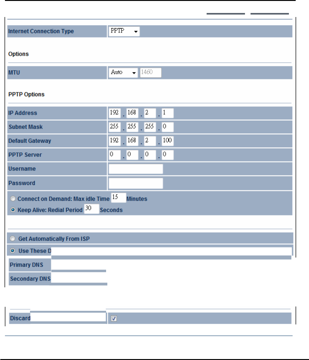
10.1.4 PPTP
(Point-to-Point Tunneling Protocol
)
Select
PPTP
as your
WAN
connection type
if
your ISP uses a Point-to-Point-Tunneling
Protocol
(PPTP)
connection.
You will
need to provide the IP address subnet
mask
default
gateway
(optional)
DNS
(optional) server
IP
usernam
e
and password provided by your ISP.
WAN
Settings
Home
Resel
!il
Use
These
DNS
Se
rve
|
o
!。I
o
!。I
o
!。I
o
WA
N
P
i
ng
PingonWAN
I
Apply
I
Internet Connection
Type
Select PPTP to begin config uration of the
PPTP
connection.

MTU
Specify
the Maximum Transmit Unit
size.
It is recommended
y
ou
accept the default setting of
A
u
t
o
.
O
t
he
r
w
i
s
e
,
p
ac
k
e
t
s
will be
fragmented downstream if the MTU is set too high or too
l
ow
,
which impacts network
pe
r
f
or
m
a
nc
e
.
In extreme
cases,
an MTU
setting that is too low can prevent the
OM2P V2
from
establishing some
c
onne
c
t
i
ons
.
IP Address
E
nt
e
r
the WAN port
IP address.
IP
S
u
b
n
e
t
Mask
E
nt
e
r
the WAN
IP
subnet
m
a
s
k
.
G
a
t
e
w
a
y
IP Address
E
nt
e
r
the WAN gateway
IP
a
ddr
e
ss
.
PPTP
S
e
r
v
e
r
E
nt
e
r
the
IP address
of the
PPTP s
e
r
v
e
r
.
Username
E
nt
e
r
the
username
provided by your
I
S
P
.
Password
E
nt
e
r
the
password
provided by your
I
S
P
.
C
onn
ec
t
on Demand If you want the
OM2P V2
to end the Internet connection after it
has been inactive for a period of
t
i
m
e
,
s
e
l
ec
t
this option and enter
t
he
number of minutes you want that period of inactivity to
l
a
s
t
.
Keep
Alive
If you want the
OM2P V2
to periodically check your
I
nt
e
r
ne
t
c
onne
c
t
i
on
,
s
e
l
ec
t
this
op
t
i
on
.
Then specify how often you
w
a
nt
the
OM2P V2
to check the Internet
c
onne
c
t
i
on
.
If the
connection is
down, the
OM2P V2
automatically
r
e
-
e
s
t
a
bl
i
s
h
e
s
your
c
onne
c
t
i
o
n
G
e
t
A
u
t
om
a
t
i
ca
ll
y
From
I
S
P
Obtains the
DNS
automatically from
DHCP
s
e
r
v
e
r
.
Use These
DNS Servers
Click
the radio button to set up the
Primary DNS
and Secondary
DNS servers
m
a
nu
a
ll
y
.
Discard
Ping on WAN
Check
to
En
a
b
l
e
to recognize pings on the
OM2P V2
WAN
interface or Disable to block pings on the
OM2P V2
WAN
int
e
r
f
ace
.
N
ot
e
:
P
i
nging
IP addresses
is a common method used
by
hackers
t
o
test whether the
IP address
is valid. Blocking pings provides some
extra security from
ha
c
k
e
r
s
.
A
cce
p
t
/
C
a
n
ce
l
Click
A
cce
p
t
to confirm the
changes
or
C
a
n
ce
l
to
cancel
and
return previous
s
e
tt
i
ngs
.
Clicking
A
cce
p
t
does not apply the
changes.
To apply
t
he
m
,
use
S
t
a
t
u
s
>
S
a
v
e
/
L
o
a
d
(see
section
4
.
1
)
.
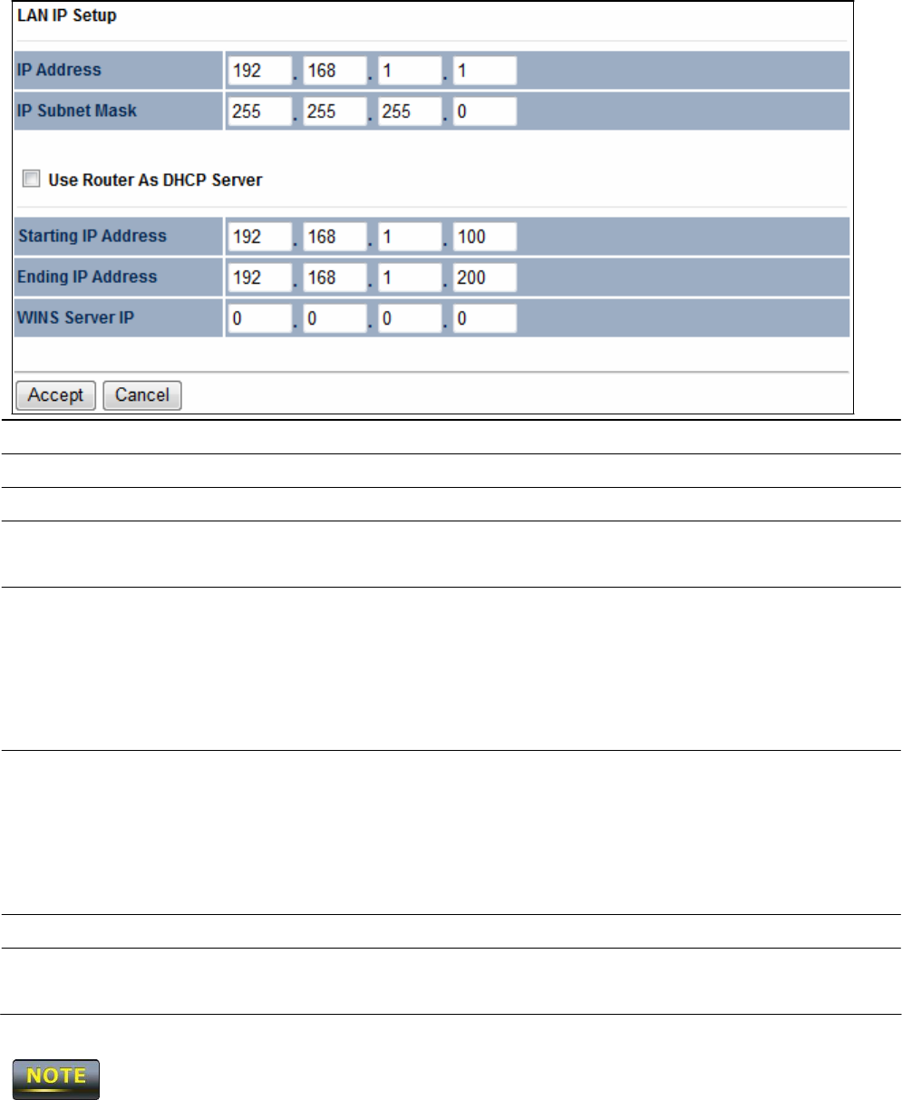
10.2
L
AN
Se
tt
in
gs
(
R
o
u
t
e
r
M
ode
)
IP Address
E
nt
e
r
the LAN port
IP
a
ddr
e
ss
.
IP
S
u
b
n
e
t
Mask
E
nt
e
r
the LAN
IP
subnet
m
a
s
k
.
W
I
N
S
S
e
r
v
e
r
IP
E
nt
e
r
the
WINS Server
I
P
.
Use
R
ou
t
e
r
As DHCP
S
e
r
v
e
r
Check
this option to enable the
OM2P V2
internal
DHCP
s
e
r
v
e
r
.
S
t
a
r
t
i
n
g
IP Address
Specify
the starting
IP address
range for the pool of allocated
f
or
private
IP addresses. The
starting
IP address
must be on the same
subnet
as
the ending
IP address;
that is the first three
oc
t
e
t
s
s
pe
c
i
f
ied here must be the
same as
the first three octets in End
IP
A
dd
r
e
ss
.
Ending
IP Address
Specify
the ending
IP address
range for the pool of allocated
f
or
private
IP addresses. The
ending
IP address
must be on the same
subnet
as
the starting
IP address;
that is the first three octets
s
pe
c
i
f
ied here must be the
same as
the first three octets in
S
t
a
r
t
IP
A
dd
r
e
ss
.
W
I
N
S
S
e
r
v
e
r
IP
E
nt
e
r
the
IP address
of the
WINS
s
e
r
v
e
r
.
A
cce
p
t
/
C
a
n
ce
l
Click
A
cce
p
t
to confirm the
changes
or
C
a
n
ce
l
to
cancel
and
return previous
s
e
tt
i
ngs
.
Clicking
A
cce
p
t
does not apply the
changes.
To apply
t
he
m
,
use
S
t
a
t
u
s
>
S
a
v
e
/
L
o
a
d
(see
section
4
.
1
)
.
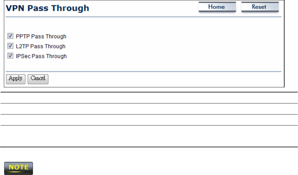
10.3
VPN
P
a
ss
T
h
r
ou
gh
VPN
P
a
ss
t
hrough
allows a
secure
virtual private network
(VPN)
connection between
t
w
o
c
om
put
e
r
s
.
E
na
bl
i
n
g
the options on this page opens a
VPN
port and
enables
connections
t
o
pass
through the
OM2P V2
without
int
e
rr
up
t
i
on
.
PPTP Pass
Through
Check
this option to enable
PPTP
pass-through
m
ode
.
L2TP Pass
Through
Check
this option to enable
L2TP
pass-through
m
ode
.
IPSec Pass
Through
Check
this option to enable
IPSec
pass-through
m
ode
.
A
cce
p
t
/
C
a
n
ce
l
Click
A
cce
p
t
to confirm the
changes
or
C
a
n
ce
l
to
cancel
and
return previous
s
e
tt
i
ngs
.
Clicking
A
cce
p
t
does not apply the
changes.
To apply
t
he
m
,
use
S
t
a
t
u
s
>
S
a
v
e
/
L
o
a
d
(see
section
4
.
1
)
.
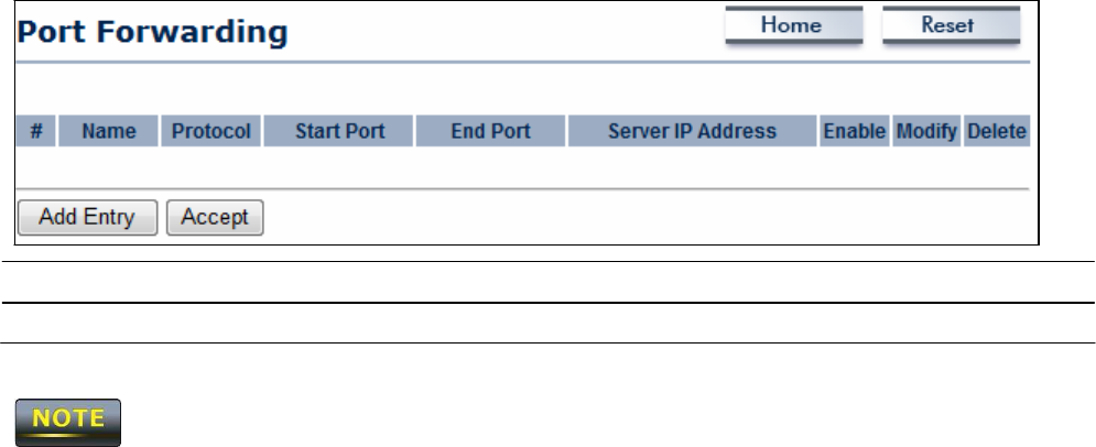
10.4
P
o
r
t
F
o
r
w
a
r
din
g
Port
forwarding can be used to open a port or range of ports to a device on your
ne
t
w
or
k
Using port forwarding, you can set up public
services
on your
ne
t
w
or
k
.
When
users
from
t
he
Internet make certain
r
e
que
s
t
s
on your
ne
t
w
or
k
,
the
OM2P V2
can forward those
r
e
que
s
t
s
t
o
computers equipped to handle the
r
e
que
s
t
s
.
I
f
,
for
exa
m
pl
e
,
you set the port number 80
(HTTP)
to be forwarded to
IP address 192.168.1.2,
all
HTTP
r
e
que
s
t
s
from outside
users
are
forwarded to
192
.
168
.
1
.
2
.
Add
En
t
r
y
Click
Add
En
t
r
y
to add port forwarding
r
ul
e
s
.
A
cce
p
t
Click
A
cce
p
t
to confirm the
c
ha
nge
s
.
Clicking
A
cce
p
t
does not apply the
changes.
To apply
t
he
m
,
use
S
t
a
t
u
s
>
S
a
v
e
/
L
o
a
d
(see
section
4
.
1
)
.
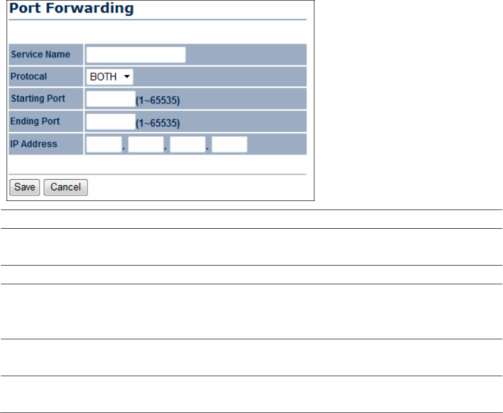
S
e
r
v
i
ce
Name
E
nt
e
r
a name for the port forwarding
r
ul
e
.
Protocol
Se
l
ec
t
a protocol for the
a
ppl
i
ca
t
i
on
:
Choices
are
B
ot
h
,
TCP,
and
U
D
P
.
S
t
a
r
t
i
n
g
P
or
t
E
nt
e
r
a starting port num
be
r
.
Ending
P
or
t
E
nt
e
r
an ending port num
be
r
.
All ports numbers between
t
he
starting and ending ports will forward
users
to the
IP
address
s
pe
c
i
f
ied in the IP Address
f
i
e
l
d.
IP Address
E
nt
e
r
the
IP address
of the
server
computer on the LAN
ne
t
w
or
k
where
users
will be
r
e
dir
ec
t
e
d
.
Save
/
C
a
n
ce
l
Click Save
to apply the
changes
or
C
a
n
ce
l
to return previous
s
e
tt
i
ngs
.
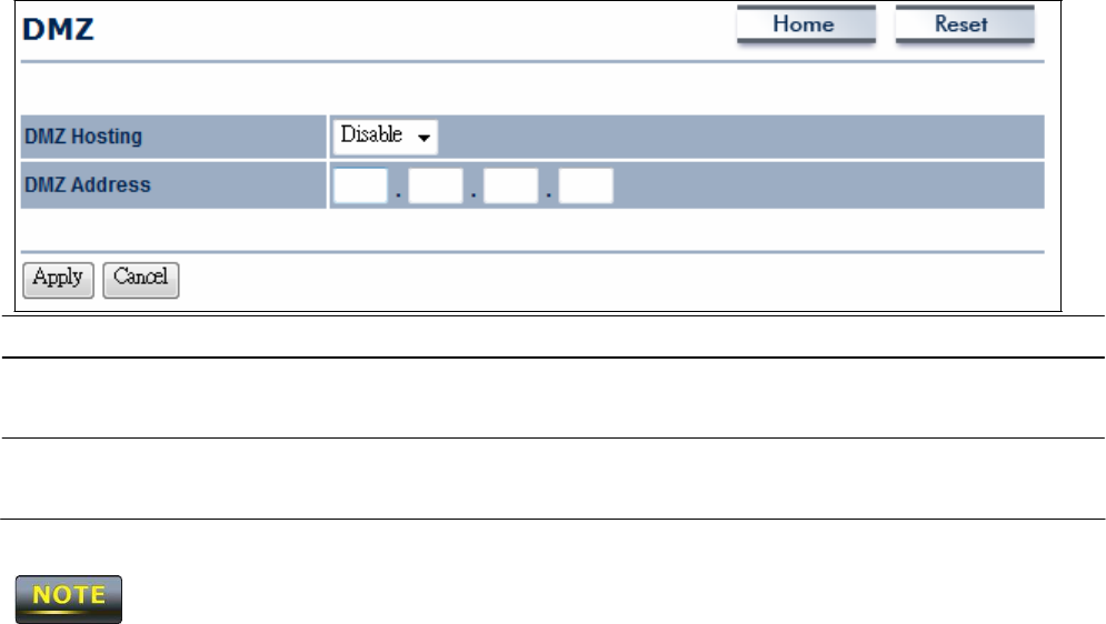
10.5
D
M
Z
If you have a computer that cannot run Internet applications properly from behind the
OM2P
V2
,
you can allow the computer to have unrestricted Internet
access.
E
nt
e
r
the
IP address
of
t
ha
t
computer
as
a Demilitarized Zone (DMZ) host with unrestricted Internet
access.
Adding a
client to the DMZ may
expose
that computer to a variety of security
risks,
so
use
this option as
a last
r
e
s
or
t
.
DMZ
H
os
t
i
n
g
E
na
bl
e
s
or
disables
the
OM2P V2
DMZ
f
unc
t
i
on
.
DMZ Address
E
nt
e
r
an
IP address
of the computer that will have
unl
i
m
i
t
e
d
Internet
acce
ss
.
A
cce
p
t
/
C
a
n
ce
l
Click
A
cce
p
t
to confirm the
changes
or
C
a
n
ce
l
to
cancel
and
return previous
s
e
tt
i
ngs
.
Clicking
A
cce
p
t
does not apply the
changes.
To apply
t
he
m
,
use
S
t
a
t
u
s
>
S
a
v
e
/
L
o
a
d
(see
section
4
.
1
)
.
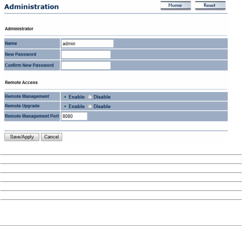
C
ha
p
t
e
r
11
M
a
n
a
g
e
me
n
t
S
e
tt
i
n
gs
The
M
a
n
a
g
e
m
e
n
t
section lets you configure administration, management
VLAN, SN
M
P
s
e
tt
i
ngs
,
backup/restore
s
e
tt
i
ngs
,
firmware
up
gr
a
de
,
time
s
e
tt
i
ngs
,
and log
s
e
tt
i
ngs
.
This
chapter
describes
these
s
e
tt
i
ngs
.
11.1
A
dmin
is
t
r
a
t
i
o
n
Click
the
A
dm
i
n
i
s
t
r
a
t
i
on
link under the
M
a
n
a
g
e
m
e
n
t
menu to change the user name and
password
used to log on to the
OM2P V2
Web Configurator
. The
default user name is
a
dm
i
n
and the default
password
is
a
dm
i
n
.
Changing these settings protects the
OM2P V2
c
onf
i
gur
a
t
i
o
n settings from being
accessed
by unauthorized
use
r
s
.
Name
E
nt
e
r
a new
username
for logging in to the Web
C
onf
i
gur
a
t
or
.
Password
E
nt
e
r
a new
password
for logging in to the Web
C
onf
i
gur
a
t
or
C
on
f
i
r
m
Password
Re-enter
the new
password
for
c
onf
i
r
m
a
t
i
on
.
Remote
M
a
n
a
g
e
m
e
n
t
E
na
bl
e
or disable remote
m
a
na
ge
m
e
nt
.
Remote Upgrade
Specify
whether the
OM2P V2
firmware can be upgraded
r
e
m
ot
e
l
y
.
Remote
M
a
n
a
g
e
m
e
n
t
P
or
t
If remote management is enabled, enter the port number to be
used for remote
m
a
na
ge
m
e
nt
.
For
exa
m
pl
e
:
If you specify
t
he
port number
8080
,
enter
h
tt
p
:
//
<
I
P
address>:8080 to access

the
OM2P V2
Web
C
onf
i
g
ur
a
t
or
.
S
a
v
e
/
A
pp
l
y
/
C
a
n
ce
l
Click
S
a
v
e
/
A
pp
l
y
to apply the
changes
or
C
a
n
ce
l
to
r
e
t
ur
n
previous
s
e
tt
i
ngs
.
Clicking
S
a
v
e
/
A
pp
l
y
changes
the settings
i
mm
e
di
a
t
e
l
y
.
You
cannot undo the
ac
t
i
on
.
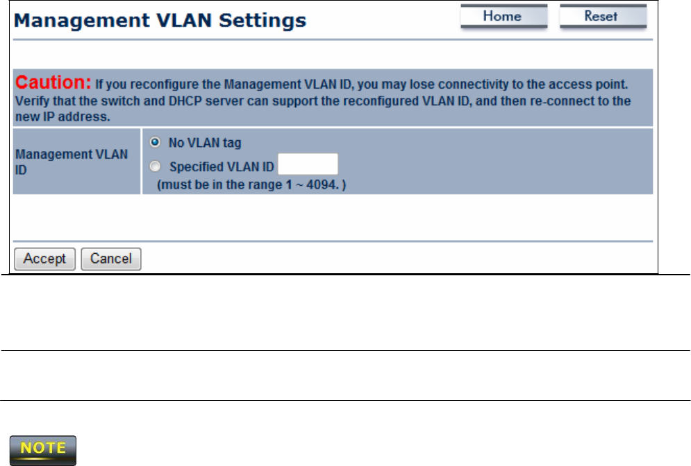
11.2
M
a
n
a
geme
n
t
V
L
A
N
Click
the
M
a
n
a
g
e
m
e
n
t
VLAN link under the
M
a
n
a
g
e
m
e
n
t
menu to
assign
a
VLAN
tag to
t
he
pa
c
k
e
t
s
.
A
VLAN
is a group of computers on a network whose software
has
been
c
onf
i
gur
e
d
so that they
behave as
if they were on a
s
e
pa
r
a
t
e
Local
Area Network
(LAN).
Computers
on
VLAN
do not have to be
physically
located next to one another on the LAN
M
a
n
a
g
e
m
e
n
t
VLAN ID If your network includes VLANs and if tagged packets need
t
o
pass through the Access
P
oi
nt
,
enter the VLAN
ID.
O
t
he
r
w
i
s
e
,
click No VLAN
t
a
g
.
A
cce
p
t
/
C
a
n
ce
l
Click
A
cce
p
t
to confirm the
changes
or
C
a
n
ce
l
to
cancel
and
return previous
s
e
tt
i
ngs
.
1.
If you reconfigure the Management
VLAN ID,
you may lose your connection to the
OM2P
V2
.
Verify that the
DHCP server
supports the reconfigured
VLAN
ID and then reconnect to
t
h
e
OM2P V2
using the new
IP
a
ddr
e
ss
.
2.
Clicking
A
cce
p
t
does not apply the
changes.
To apply
t
he
m
,
use
S
t
a
t
u
s
>
S
a
v
e
/
L
o
a
d
(see
section
4
.
1
)
.
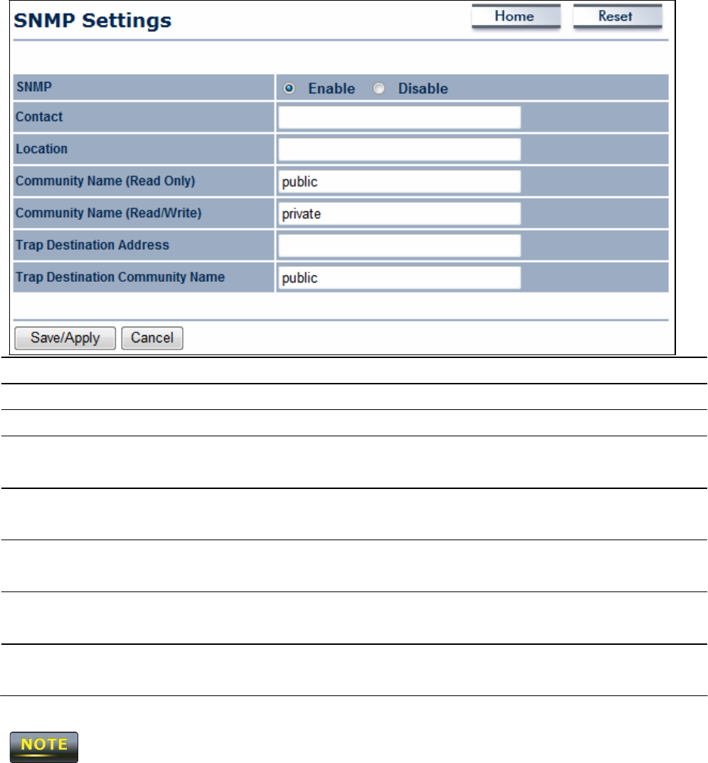
11.3
SNMP
S
e
t
t
i
n
gs
Click
the
S
N
M
P
S
e
tt
i
n
g
s
link under the
M
a
n
a
g
e
m
e
n
t
menu to monitor
ne
t
w
or
k
-
a
tt
ac
he
d
devices
using the Simple Network Management
P
r
ot
oc
ol
(SNMP). SNMP
allows messages
(called “protocol data unit’s) to be sent to various parts of a
ne
t
w
or
k
.
Upon receiving these
messages,
SNMP-compatible devices
(called agents) return data stored in their
M
a
na
ge
m
e
nt
Information
Ba
s
e
s
.
S
N
M
P
En
a
b
l
e
/
D
i
s
a
b
l
e
E
na
bl
e
or disable the
OM2P V2 SNMP
f
unc
t
i
on.
C
on
t
ac
t
E
nt
e
r
the contact details of the
de
v
i
ce
.
L
oc
a
t
i
on
E
nt
e
r
the location of the
de
v
i
ce
.
C
omm
un
i
t
y
Name
E
nt
e
r
the
password
for
accessing
the
SNMP
community
f
or
read-only
acce
ss
.
C
omm
un
i
t
y
Name
E
nt
e
r
the
password
for
accessing
the
SNMP
community for read
and write
acce
ss
.
Trap D
e
s
t
i
n
a
t
i
on
IP
A
dd
r
e
ss
Trap D
e
s
t
i
n
a
t
i
on
C
omm
un
i
t
y
N
a
m
e
E
nt
e
r
the
IP address
where
SNMP
traps are to be
s
e
nt
.
E
nt
e
r
the
password
of the
SNMP
trap
c
ommuni
t
y
.
S
a
v
e
/
A
pp
l
y
/
C
a
n
ce
l
Click
S
a
v
e
/
A
pp
l
y
to apply the
changes
or
C
a
n
ce
l
to
r
e
t
ur
n
previous
s
e
tt
i
ngs
.
Clicking
S
a
v
e
/
A
pp
l
y
change the setting
i
mm
e
di
a
t
e
l
y
.
You
cannot undo the action.
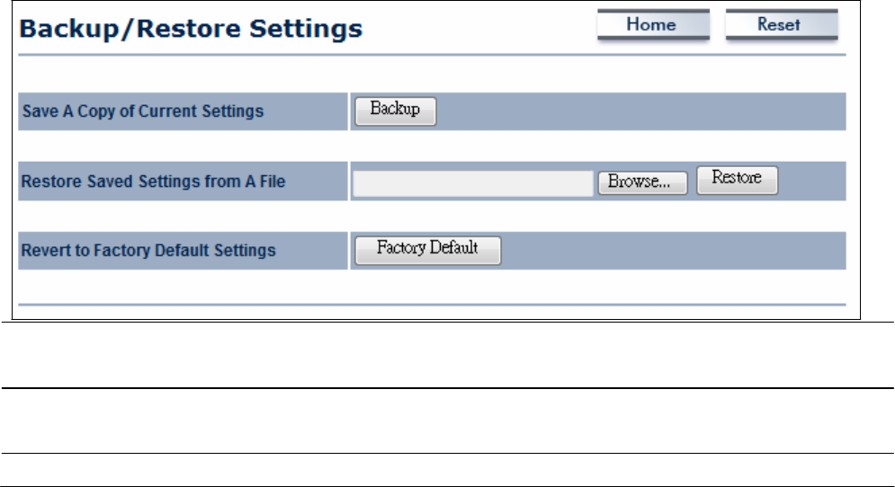
11.4
B
a
c
k
u
p
/
R
e
s
t
o
r
e
Se
tt
in
gs
Click
the
B
ac
k
u
p
/
Re
s
t
or
e
S
e
tt
i
n
g
link under the
M
a
n
a
g
e
m
e
n
t
menu to
save
the
OM2P
V2
’
s
current settings in a file on your local disk or load settings onto the device from a local
di
s
k
.
This
feature is particularly convenient administrators who have
several OM2P V2
devices
t
ha
t
need to be configured with the
same
s
e
tt
i
ngs
.
This
page also lets you return the
OM2P V2
to its factory default
s
e
tt
i
ng
s
.
If you perform
t
hi
s
pr
oc
e
dur
e
,
any
changes
made to the
OM2P V2
default settings will be
l
os
t
.
Save
A Copy
o
f
C
u
rr
e
n
t
S
e
tt
i
n
g
s
R
e
s
t
or
e
Saved
S
e
tt
i
n
g
s
from
a
F
il
e
R
e
v
e
r
t
to
F
ac
t
or
y
D
e
f
a
u
l
t
S
e
tt
i
n
g
s
Click
Backup to
save
the current configured
s
e
tt
i
ngs
.
To restore settings that have been previously backed
up
,
click
B
r
ow
s
e
,
s
e
l
ec
t
the
f
il
e
,
and click
R
e
s
t
or
e
.
Click
this button to restore the
OM2P V2
to its factory
de
f
a
ul
t
s
e
tt
i
ngs
.
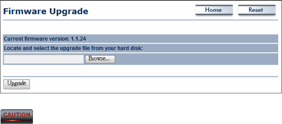
11.5
F
irmw
a
re
U
p
gr
a
de
Click
the
F
i
r
mw
a
r
e
Upgrade link under the
M
a
n
a
g
e
m
e
n
t
menu to upgrade the firmware
of
the
de
v
i
ce
.
To perform this
pr
oc
e
dur
e
,
downloaded the appropriate firmware from
y
our
v
e
ndor
.
The firmware upgrade procedure can
t
a
ke
few
m
i
nut
e
s
.
Do
not
power
off the
OM2P V2 during
the
firmware upgrade,
as
it
can cause
the
device
to
crash
or
become unusable. The OM2P V2
r
e
s
t
a
r
t
s
a
ut
om
a
t
i
c
a
ll
y
after the
upgrade
c
om
pl
e
t
e
s
.
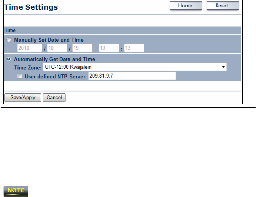
11.6
T
ime
Se
tt
in
gs
Click
the Time
S
e
tt
i
n
g
s
link under the
M
a
n
a
g
e
m
e
n
t
menu to configure the
OM2P V2
system
t
i
m
e
.
You can enter the time manually
or
,
to
ensure accuracy, synchronize
the
OM2P V2
w
i
t
h
Network Time
P
r
ot
oc
ol
(NTP)
s
e
r
v
e
r
.
Manually
S
e
t
D
a
t
e
a
n
d
T
i
m
e
A
u
t
om
a
t
i
ca
ll
y
G
e
t
D
a
t
e
and
T
i
m
e
Manually specify the date and
t
i
m
e
.
Se
l
ec
t
a time zone from the drop-down list and check
whe
t
he
r
you want to enter the
IP address
of an
NTP server
or
use
t
he
default
NTP
s
e
r
v
e
r
.
S
a
v
e
/
A
pp
l
y
/
C
a
n
ce
l
Click
S
a
v
e
/
A
pp
l
y
to apply the
changes
or
C
a
n
ce
l
to
r
e
t
ur
n
previous
s
e
tt
i
ngs
.
Clicking
S
a
v
e
/
A
pp
l
y
changes
the setting
i
mm
e
di
a
t
e
l
y
.
You
cannot undo the
ac
t
i
on
.
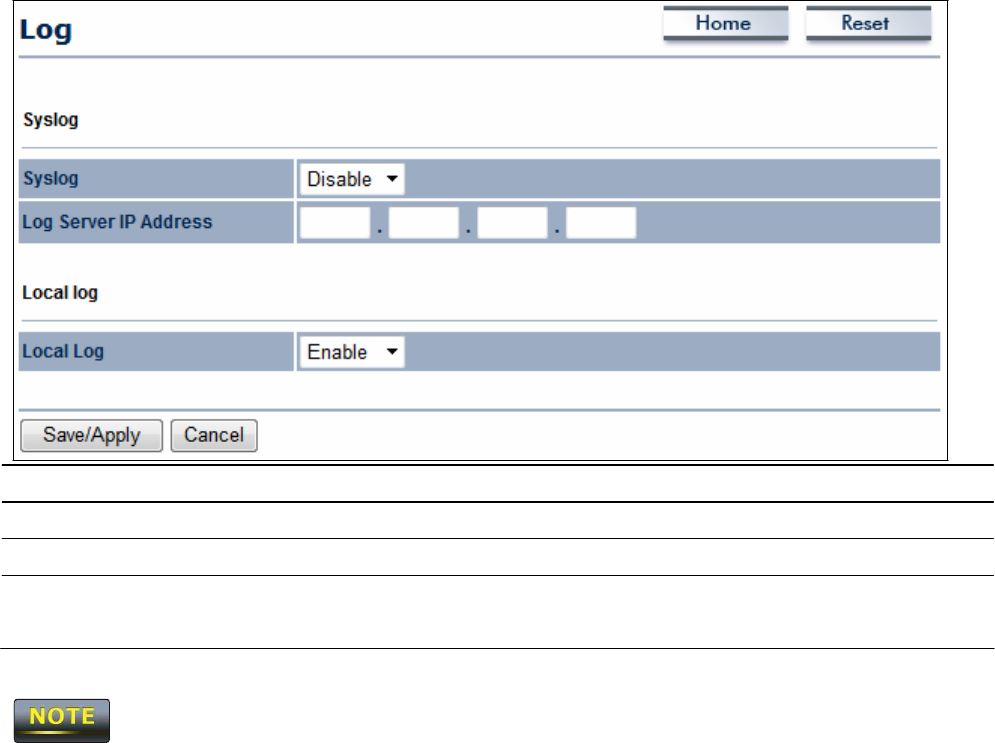
11.7
Log
Click
the Log link under the
M
a
n
a
g
e
m
e
n
t
menu to display a list of events that are
t
r
i
gge
r
e
d
on the
OM2P V2
E
t
he
r
ne
t
and
wireless
int
e
r
f
ace
s
.
You can consult this log if an unknown
e
rror
occurs
on the
s
y
s
t
e
m
or when a report
needs
to be sent to the technical support
depa
r
t
m
e
nt
for debugging
pur
pos
e
s
.
S
y
s
l
og
E
na
bl
e
or disable the
OM2Psyslog
f
unc
t
i
on
.
Log
S
e
r
v
e
r
IP Address
E
nt
e
r
the
IP address
of the log
s
e
r
v
e
r
.
L
oc
a
l
Log
E
na
bl
e
or disable the local log
s
e
r
v
i
ce
.
S
a
v
e
/
A
pp
l
y
/
C
a
n
ce
l
Click
S
a
v
e
/
A
pp
l
y
to apply the
changes
or
C
a
n
ce
l
to
r
e
t
ur
n
previous
s
e
tt
i
ngs
.
Clicking
S
a
v
e
/
A
pp
l
y
changes
the settings
i
mm
e
di
a
t
e
l
y
.
You
cannot undo the
ac
t
i
on
.
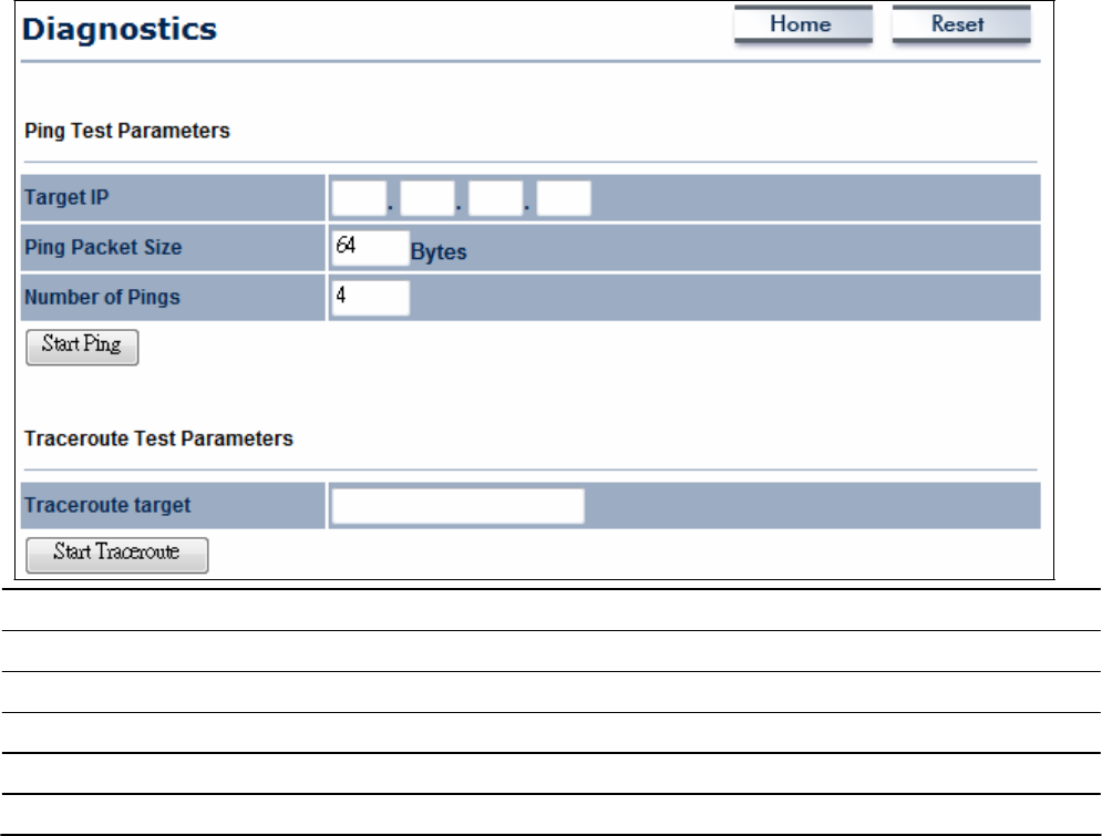
11.8
D
ia
gn
o
s
t
ic
s
Click
the D
i
a
g
n
os
t
i
c
s
link under the
M
a
n
a
g
e
m
e
n
t
menu to
a
s
ce
r
t
a
i
n connection quality and
trace the routing table to the
t
a
r
ge
t
.
Ta
r
g
e
t
IP
E
nt
e
r
the
IP address
you would like to search.
Ping
P
ac
k
e
t
S
i
ze
E
nt
e
r
the packet
size
of
each
pi
ng.
Number
of
Pings
E
nt
e
r
the number of times you want to
pi
ng.
S
t
a
r
t
Ping
Click
S
t
a
r
t
Ping to begin
pi
nging
.
T
r
ace
r
ou
t
e
Ta
r
g
e
t
E
nt
e
r
an
IP address
or domain name you want to
t
r
ace
.
S
t
a
r
t
T
r
ace
r
ou
t
e
Click
S
t
a
r
t
T
r
ace
r
ou
t
e
to begin the trace route ope
r
a
t
i
on
.

C
ha
p
t
e
r
12
N
e
t
w
o
r
k
C
o
n
f
igu
r
a
t
i
on
E
x
a
m
p
le
s
This
chapter provides step-by-step descriptions for using the
OM2P V2’s
operating
m
ode
s
.
The
Access
P
oi
nt
Mode’s default configuration allows the
OM2P V2
to act
as
a central unit of
a WLAN or
as
a root device of a wired
e
nv
i
r
onm
e
nt
.
R
e
pe
a
t
e
r
mode and Mesh network mode
are
reserved
for future
c
on
f
i
gur
a
t
i
on
.
12.1
Access
P
oin
t
Access
P
o
i
n
t
S
t
e
p1 Log in to the Web Configurator with your browser by
e
nt
e
r
i
ng
the default
IP address
192
.
168
.
1
.
1
S
t
e
p2
Use
site
survey
to
scan channels available
in nearby
a
r
ea
s
.
S
t
e
p3
Se
l
ec
t
channel with
less
int
e
r
f
e
r
e
nc
e
s
.
Specify
the
SSID
for your broadcast
SSID
and you can also
S
t
e
p4
configure multiple
SSID
at the
same
t
i
m
e
.
S
t
e
p5 Verify the
VLAN
identif ier to
s
e
p
a
r
a
t
e
services
among clients
S
t
e
p6
Se
t
the authentication
s
e
tt
i
ngs
.
S
t
e
p7
Click
Apply
to
save
all
c
ha
nge
s
.
For
more
advanced
s
e
tt
i
ngs
,
refer to the previous
c
ha
p
t
e
r
s
.

W
i
r
e
l
e
ss
Cl
i
e
n
t
S
t
e
p1
Se
l
ec
t
the
wireless
mode with which you want to
a
ss
oc
i
a
t
e
.
Use
site
survey
to
scan
nearby
Access
P
oi
nt
and either
s
e
l
ec
t
t
he
S
t
e
p2
Access
P
oi
nt
to which you want to
c
onne
c
t
,
or enter the
SSI
D
m
a
nua
ll
y
.
S
t
e
p3 Configure the
VLAN
ID in your
wireless
device if
a
v
a
il
a
bl
e
.
S
t
e
p4
Se
l
ec
t
the appropriate authentication type and password.
Access
P
oi
nt
Mode does not provide
DHCP server,
so the
Wireless
Client
IP
address
must be configured manually using the
same Local
Area Network
s
ubne
t
.
12.2
C
lie
n
t
Bridge
Mode
Client Bridge Mode functions like a
wireless
dongl
e
.
It must connect to an
Access
P
oi
nt
/
AP
Router
to join the
ne
t
w
or
k
.
Refer
to Chapter 13 to check the
Access Point’s c
onf
i
gur
a
t
i
on
.
Cl
i
e
n
t
Br
i
dge
S
t
e
p1 Log in to the Web Configurator with the default
IP
address
192
.
168
.
1
.
1
S
t
e
p2
For
O
p
e
r
a
t
i
on
M
od
e
,
s
e
l
ec
t
C
li
e
n
t
Bridge
from
S
y
s
t
e
m
Pr
op
e
r
t
i
e
s
.
Use
site
survey
to
scan Access
P
oi
n
t
s
that are
available
in nearby
S
t
e
p
3
a
r
ea
s
.
S
t
e
p
4
Se
l
ec
t
the
Access
P
oi
nt
with which you want to
a
ss
oc
i
a
t
e
.
Se
t
up the authentication settings that match the
Access
P
oi
nt
’
s
S
t
e
p
5
s
e
tt
i
ng
s
.
S
t
e
p
6
Click
Apply
to
save
all
c
ha
nge
s
.
The
Client Bridge
IP
settings must match the
Access Point’s
s
ubne
t
.

12.3
WDS
Bridge
Mode
Use
this feature to link multiple
Access Points
in a
ne
t
w
or
k
.
All clients
a
ss
oc
i
a
t
e
d
with any
Access Points
can communicate with
each
other in an ad-hoc
m
a
nn
e
r
.
W
D
S
Br
i
dge
S
t
e
p1 Log in to the Web Configurator with the default
IP
address
192
.
168
.
1
.
1
S
t
e
p2
For
O
p
e
r
a
t
i
on
M
od
e
,
s
e
l
ec
t
WDS
Bridge
from
S
y
s
t
e
m
Pr
op
e
r
t
i
e
s
.
S
t
e
p3
Se
l
ec
t
the channel you want to
use
.
S
t
e
p
4
Se
t
up the authentication settings
S
t
e
p5
Se
t
up
WDS
Link
Se
tt
i
n
gs
.
S
t
e
p
6
Specify
the MAC
address
of the
Access
P
oi
nt
with which you
w
a
n
t
to
c
onne
c
t
.
S
t
e
p7
Click
Apply
to
save
all
c
ha
nge
s
.
Each WDS
bridge device must
use
the
same
S
u
b
n
e
t
,
Wireless
M
od
e
,
W
i
r
e
l
e
ss
C
h
a
nn
e
l
,
and
S
ec
u
r
i
t
y
S
e
tt
i
n
g
.

12.4
C
lie
n
t
R
o
u
t
e
r
In Client
Router
M
ode
,
the
OM2P V2’s
internal
DHCP server
allows
LANs
to
a
ut
om
a
t
i
ca
ll
y
generate an
IP address
to
share
the
same
I
nt
e
r
ne
t
.
Connect an
Access
P
oi
nt
/
W
I
SP
wirelessly
and connect to
LANs
using a wired
c
onne
c
t
i
on
.
Refer
to Chapter 13 to check the
Access Point’s c
onf
i
gur
a
t
i
on
.
Cl
i
e
n
t
R
o
u
t
e
r
S
t
e
p1 Log in to the Web Configurator with the default
IP
address
192
.
168
.
1
.
1
S
t
e
p2
For
O
p
e
r
a
t
i
on
M
od
e
,
s
e
l
ec
t
C
li
e
n
t
R
ou
t
e
r
from
S
y
s
t
e
m
Pr
op
e
r
t
i
e
s
.
S
t
e
p3
Change
your
L
oc
a
l
Area
N
e
t
w
ork
setting to
O
b
t
a
i
n
an IP
Address
A
u
t
om
a
t
i
ca
ll
y
.
Use
site
survey
to
scan Access Points
that are
available
in nearby
S
t
e
p
4
a
r
ea
s
.
S
t
e
p
5
Se
l
ec
t
the
Access
P
oi
nt
with you want to
a
ss
o
c
i
a
t
e
.
Se
t
up authentication settings that match the
Access
P
oi
nt
’
s
S
t
e
p
6
s
e
tt
i
ng
s
.
S
t
e
p7
Se
t
your WAN connection type using the WAN settings
pr
ov
i
de
d
by your
I
SP
.
S
t
e
p
8
Click
Apply
to
save
all
c
ha
nge
s
.
Client
Router’s IP
setting must match to the
Access Point’s
s
ubne
t
.
C
ha
p
t
e
r
13
Building
a Wireless
N
e
t
w
or
k
With its ability to operate in various operating
m
ode
s
,
your
OM2P V2
is the ideal device
a
r
ound
which you can build your
WLAN. This
appendix
describes
how to build a
WLAN
around
y
o
ur
OM2P V2
using he
device’s
operating
m
ode
s
.

13.1
Access
P
oin
t
Mode
In
Access
P
oi
nt
M
ode
,
OM2P V2 behaves
likes a central connection for stations or clients
t
ha
t
support
IEEE
802
.
11
b/g/
n
ne
t
w
or
k
s
.
S
t
a
t
i
o
ns
and client must be
c
onf
igured to
use
the same
SSID
and security
password
to
a
ss
oc
i
a
t
e
with the
OM2P V2. The OM2P V2
supports four
SSIDs
at
t
h
e
same
time for
secure
guest
acce
ss
.
13.2
Access
P
oin
t
Mode
with
WDS
F
un
c
t
i
on
The OM2P V2 Access
P
oi
nt
Mode also supports
WDS
f
unc
t
i
on
a
li
t
y
.
This
operating mode
allows
wireless
connections to the
OM2P V2
using
WDS
t
ec
hnol
ogy
.
In this
m
ode
,
c
onf
igure
the MAC
addresses
in both
Access Points
to enlarge the
wireless area
by enabling
WDS
Link
s
e
tt
i
ngs
.
WDS
supports eight
AP
MAC
a
ddr
e
ss
e
s
.
Not every
Access
P
oi
nt
device supports
WDS
in
Access
P
oi
nt
M
ode
.
As
a
r
e
s
ul
t
,
to
use
W
D
S,
we recommend you
use
the
OM2P V2
.

13.3
C
lie
n
t
Bridge
Mode
In Client Bridge
M
ode
,
the
OM2P V2 behaves
like a
wireless
client that connects to an Access
P
oi
nt
wirelessly
and allows
users
to surf the Internet whenever they
w
a
nt
.
In this
m
ode
,
use
the
OM2P V2
Site
Survey
to
scan
for
Access Points
within
r
a
nge
.
Then configure the
OM2P
V2
SSI
D
and security password accordingly to
a
ss
oc
i
a
t
e
with the
Access
P
oi
nt
.
In this
c
onf
i
gur
a
t
i
o
n,
the station
has
a wired
E
t
he
r
ne
t
connection to the
OM2P V2
LAN
por
t
.
13.4 WDS Bridge
Mode
In
WDS
Bridge
M
ode
,
the
OM2P V2
can
wirelessly
connect different
LANs
by configuring
t
he
MAC
address
and security settings of
each OM2P V2
de
v
i
ce
.
Use
this mode when two wired
LANs located a small distance apart want to communicate with
each
ot
he
r
.
The
best solution
is
t
o
use
the
OM2P V2
to
wirelessly
connect two wired
LANs, as
shown in the following
f
i
gur
e
.
W
D
S
Bridge Mode can
e
s
t
a
b
li
s
h 16
WDS
li
nk
s
,
creating a star-like
ne
t
w
or
k
.
WDS
Bridge Mode is unlike
Access
P
oi
nt
.
Access Points
linked by
WDS
are using the same
frequency
c
ha
nne
l
,
more
Access Points
connected together may lower
t
hroughp
ut
.
Please
be
aware
to avoid loop in your
wireless
c
onne
c
t
i
on
,
otherwise enable
S
p
a
nning
Tree
F
unc
t
i
on.
13.5
C
lie
n
t
R
o
u
t
e
r
Mode
In Client
Router
M
ode
,
the
OM2P V2’s
internal
DHCP server
allows a number of
LANs
t
o
automatically generate
IP addresses
to
share
the
same
I
nt
e
r
ne
t
.
In this
m
ode
,
connect an
AP
/
W
I
SP
wirelessly
and connect to
LANs
via a wired
c
onne
c
t
i
on
.
13.6 RADIUS
C
on
n
e
c
t
ion
s
Remote
Authentication Dial In
User Service (RADIUS)
authentication is
available
when
configuring the
OM2P V2 wireless advanced
settings
(see
Chapter
8). Use
this feature if you
have a
RADIUS server. WPA(TKIP), WPA2(AES),
and
WPA2
Mixed encryption types are also
s
up
por
t
e
d.
The
following figure
shows
an example of a
RADIUS
c
onf
i
gur
a
t
i
on
,
where two
OM2P V2
devices installed at different locations communicate with
each
other
wirelessly.
In this
c
onf
i
gur
a
t
i
on,
one
OM2P V2
is configured for
Access
P
oi
nt
Mode and connected to a
RADIUS
server
via a switch, while the other
OM2P V2
is configured for Client Bridge
M
ode
.
The
RADIUS server
uses an authentication
scheme
such
as PAP
or
CHAP
to verify a
use
r
'
s
identification, along
w
i
t
h
,
op
t
i
ona
ll
y
,
other information related to the
r
e
que
s
t
,
such
as
the
use
r
'
s
network
address
or
phone num
be
r
,
account status and
s
pe
c
i
f
ic network
service access
pr
i
v
il
e
ge
s
.
The
R
ADI
US
server
then returns one of three
responses
to the
OM2P V2 : Access
R
e
j
ec
t
(user
is denied access to all requested network
resources), Access Challenge
(
r
e
que
s
t
s
additional information
f
r
om
the user such
as
a
secondary
p
a
ss
w
or
d)
,
PIN,
token or
card),
or
Access
Accept
(user
is
gr
a
nt
e
d
acce
ss
)
.

Appendix A –
T
r
o
ub
l
e
s
h
oo
t
i
n
g
T
h
i
s
appendix provides problem-solving
information
you may
find
useful
in
case you need
t
o
t
r
oub
l
e
s
hoo
t
your
OM2P V2.
It
also includes
information about
c
on
t
a
c
t
i
n
g
t
e
c
hn
i
c
a
l
s
uppo
r
t
.
A.1 Problem
S
o
l
v
i
n
g
Q
u
e
s
t
i
on
A
n
s
w
e
r
How
do I
r
e
s
e
t
the
OM2P V2?
There are
two
ways
to
r
e
s
e
t
the
OM2P V2,
a
hardware method and a
s
o
f
t
w
a
r
e
method.
B
o
t
h
m
e
t
ho
ds
return the
OM2P V2
to
i
t
s
f
a
c
t
or
y
default configuration.
To use
the
hardware method, open
the cover
on
the bottom
panel
of the
OM2P V2 and
find
the
R
e
s
e
t
button
(see
s
e
c
t
i
on
2.1). Using a
flat
object
such as a pencil, press
the
R
e
s
e
t
button
for
a
ppr
o
x
i
m
a
t
e
l
y
10 seconds
and then
s
t
op
pr
e
ss
i
ng.
To use
the
s
o
f
t
w
a
r
e
method,
click
R
e
s
t
o
r
e
t
o
F
a
c
t
o
r
y
De
f
a
u
l
t
in the
M
a
n
a
g
e
m
e
n
t
menu.
Why do
I not
see
traffic
pass
after I
c
on
ne
c
t
the
OM2P V2
to
a PoE
s
wi
t
c
h?
The OM2P V2 uses a
proprietary
PoE
injector
and will not
work
with
s
t
a
nd
a
r
d
802
.
3
a
f
-
c
om
pl
i
a
n
t
W
ha
t
is
the
default
IP address
of the
OM2P V2?
The
default
IP address is
192.168.1.1
I
plugged
the
PoE
to the
second
E
t
he
r
ne
t
p
or
t
on
the
back
of
OM2P V2
but the unit
is
not
on,
how
c
om
e
?
You need
to
plug
the
E
t
h
e
r
ne
t
cable
c
o
nne
c
t
t
o
PoE
injector
to the
main LAN
port.
T
he
secondary
E
t
he
r
ne
t
port
is
just an
additional
LAN
port for
regular
E
t
he
r
ne
t
c
o
nne
c
t
i
on
s
uc
h
as IP
camera
When
I
i
ns
t
a
ll
the
PoE
c
o
nne
c
t
i
on
to the
OM2P
V2
,
what kind
of
PoE should
I
us
e
?
The OM2P V2 uses a
proprietary
PoE
injector
and will not
work
with
s
t
a
nd
a
r
d
802
.
3
a
f
-
c
om
pl
i
a
n
t
I
want
to
use higher gain
a
n
t
e
nna
s
on
the
OM2P V2,
but I don’t
know what
a
n
t
e
nna
is
rig
h
t
.
Use
the
a
n
t
e
nna
appropriate
for the frequency.
(2.4
GH
z
)
I
want
to
buy a high-gain
a
n
t
e
nna
for the
OM2P V2,
but I don’t
know what type
of
antenna
and RF
c
onne
c
t
or
to buy.
Use an
a
n
t
e
n
na
with
a
S
M
A
c
on
ne
c
t
o
r
t
o
c
onne
c
t
to the
OM2P V2
.
85
A.2
C
on
t
a
c
t
i
n
g
Technical
S
uppo
r
t
If you encounter issues that cannot be resolved using this manual, please contact your vendor where you
purchase the device. If you cannot contact your vendor, you may also contact EnGenius Customer Service
department in the region where you purchased the device.
Before you contact your local EnGenius office, please prepare the following information:
Product model name and serial number
The place where you purchased the product
Warranty information
The date when you received the product
A brief description about the issue and the attempts you tried to resolve it
To contact EnGenius Customer Service office in the United States, please use either of the following methods:
Email: Support@EnGeniustech.com
Telephone: 1-888-735-7888

Appendix
C –
G
l
o
ss
a
ry
Access
P
o
i
n
t
A base station in a WLAN that act as a central transmitter and receiver of WLAN radio signals.
Ad Hoc
Network
A short-term WLAN framework created between two or more WLAN adapters, without going
through an Access Point. An ad hoc network lets computers send data directly to and from one
another. For an ad hoc network to work, each computer on the network needs a WLAN card
installed configured for Ad Hoc mode.
Antenna
A device that sends and receives radio-frequency (RF) signals. Often camouflaged on existing
buildings, trees, water towers or other tall structures, the size and shape of antennas are generally
determined by the frequency of the signal they manage.
Authentication
A process that verifies the identity of a wireless device or end-user. A common form of
authentication is to verify identities by checking a user name and password to allow network
access.
B
a
c
kbon
e
A high-speed line
or
series
of
c
on
ne
c
t
i
o
ns
that form
a major
p
a
t
h
w
a
y
within
a
network.
B
a
nd
w
i
d
t
h
The
part of the
frequency
s
pe
c
t
r
um
required
to
transmit
desired
information.
Each radio
channel
has a
c
e
n
t
e
r
frequency and
additional
frequencies above and below
t
hi
s
carrier frequency
that
carry
the
transmitted information.
The range
of
frequencies
from the
l
ow
e
s
t
to the
hi
g
h
e
s
t
used
is called
the bandwidth.
B
r
i
d
g
e
A wireless device that connects multiple networks that are physically separate or use different
media, but which use similar standards.
Bridge
Mode
An Access
P
oi
n
t
y
in
bridge mode can
op
e
r
a
t
e
as a WLAN bridge
that
c
on
ne
c
t
s
two
wired
network
s
e
g
m
e
n
t
s
.
The peer device also
m
us
t
be
in
bridge mode. This wireless bridge
c
onne
c
t
i
on
is
e
qui
v
a
l
e
n
t
to
a Wireless
D
i
s
t
r
i
b
uti
on
S
y
s
t
e
m
(
W
DS
).
CHAP
Challenge Handshake
Authentication
P
r
o
t
oc
ol
.
An
a
l
t
e
r
na
t
i
ve
protocol
that
uses
a
c
ha
ll
enge
/
r
e
s
pons
e
t
e
c
h
ni
qu
e
i
ns
t
e
a
d
of
sending passwords over
the wire.
Co
lli
s
i
on
Interference resulting from two network devices sending data at the same time. The network
detects the collision of the two transmitted packets and discards both of them.
Co
v
e
r
a
g
e
The region within which a paging receiver can reliably receive the transmission of paging signals.
Coverage
Area
The geographical area that can be served by a mobile communications network or system.
Coverage
Hole
An area within the radio coverage footprint of a wireless system where the RF signal level is
below the design threshold. Physical obstructions such as buildings, foliage, hills, tunnels, and
indoor parking garages are usually the cause of coverage holes.
Cy
c
li
c
Redundancy Check
(
CR
C)
A common
t
e
c
hni
que
for
de
t
e
c
t
i
ng
da
t
a
t
r
a
ns
m
i
ss
i
on
e
rr
or
s
.
Dynamic Ho
s
t
C
on
f
i
g
u
r
a
t
i
on
Pr
o
t
o
c
o
l
(
DHCP)
A protocol that assigns temporary IP addresses automatically to client stations logging onto an IP
network, so the IP addresses do not have to be assigned manually. The OM2P V2 contains an
internal DHCP server that automatically allocates IP address using a user-defined range of IP
addresses.
Dead
S
po
t
An area within the coverage area of a WLAN where there is no coverage or transmission falling
off. Electronic interference or physical barriers such as hills, tunnels, and indoor parking garages
are usually the cause of dead spots. See also coverage area.
802.11
A category of WLAN standards defined by the Institute of Electrical and Electronics Engineers
(IEEE).
802.11a
An IEEE standard for WLANs that operate at 5 GHz, with data rates up to 54 Mbps.
802.11b
An IEEE standard for WLANs that operate at 2.4 GHz, with data rates up to 11 Mbps.
802.11g
An IEEE s
t
a
nd
a
r
d
for
WLANs
that
op
e
r
a
t
e
s
at
2.4 GHz,
with
da
t
a
rate
of
300 Mbps. The
new
s
t
a
n
da
r
d
also raises
the
encryption bar
to
WPA2. The 40 HT
option
can be added
to
increase
the
da
t
a
rate.
E
n
c
r
y
p
t
i
on
Translates data into a secret code to achieve data security. To read an encrypted file, you must
have a secret key or password for decryption. Unencrypted data is referred to as plain text;
encrypted data is referred to as cipher text
ESS
ID
The
unique identifier
for
an
E
SS
.
All Access
P
oi
n
t
s
and
their
a
ss
oc
i
a
t
e
d
wireless
s
t
a
t
i
o
ns
in the
same group
m
us
t
have
the
same
E
SS
I
D
.
F
oo
t
p
r
i
n
t
Geographical areas where an
entity
is licensed
to
br
oadc
a
s
t
i
t
s
s
i
g
na
l
.
G
a
t
e
w
a
y
A computer
s
y
s
t
e
m
or other
device
that
a
c
t
s
as a
translator
be
t
w
ee
n
two
s
y
s
t
e
m
s
that
u
s
e
different
c
om
muni
c
a
t
i
on
pr
o
t
oc
ol
s
,
da
t
a
formatting
s
t
r
uc
t
ur
e
s
,
languages,
and/or architecture.
HT mode
In the
802.11n
s
y
s
t
e
m
,
two
new
f
or
m
a
t
s
,
called High
T
hr
o
ug
hpu
t
(HT), are defined
for the
Physical Layer, Mixed Mode, and Green Field.
If
a
s
y
s
t
e
m
runs 40 HT,
two
a
dj
a
c
e
n
t
20
M
H
z
channels are used. The larger 40 MHz bandwidth can provide
better
transmit quality and
s
pe
e
d.
K
e
y
s
Like passwords, keys open
(
de
c
r
y
p
t
)
and close (encrypt) messages. While many
encryption
a
l
g
or
i
t
hm
s
are commonly known and public,
the
key
m
us
t
be
ke
p
t
s
e
c
r
e
t
.
Local-Area
Network
(
L
AN)
A small
da
t
a
network
covering a
limited
area, such as a building
or
group
of
buildings.
Most
L
ANs
c
onne
c
t
wor
k
s
t
a
t
i
o
ns
or
personal
c
omp
ut
e
r
s
.
LANs
let
many users share devices such as
pr
i
n
t
e
r
s
as
well
as
da
t
a
.
LANs also
facilitate
c
om
m
u
ni
c
a
t
i
on
through e-mail
or
c
ha
t
s
e
ss
i
o
ns
.
Media
Access Co
n
t
r
o
l
(MAC)
A
dd
r
e
ss
Address
a
ss
oc
i
a
t
e
d
with
every hardware device
on the
network.
Every 802.11 wireless device
ha
s
i
t
s
own specific MAC address. This
unique identifier
is hard-coded
into the
device and can
be
used
to
provide
s
e
c
ur
i
t
y
for
WLANs. When a
network
uses a MAC
t
a
bl
e,
only
the
802.11
radios
that
have
their
MAC addresses added
to that
ne
t
wor
k
'
s
MAC
t
a
bl
e
can access
the network.
Network
Address
T
r
a
n
s
l
a
t
i
on
(NA
T
)
An Internet
s
t
a
nda
r
d
that
l
e
t
s
a LAN use one
s
e
t
of
IP addresses
for
internal
traffic
and a
s
e
c
ond
s
e
t
of
addresses
for
e
x
t
e
r
na
l
traffic.
Network
Time
Pr
o
t
o
c
o
l
(N
T
P)
A protocol
that
l
e
t
s
devices synchronize
their time with
a
time
server. NTP uses
TCP
or
UDP
po
r
t
123 by
default.
P
a
ss
ph
r
a
s
e
A
text
s
t
r
i
ng
that
a
u
t
om
a
t
i
c
a
ll
y
g
e
ne
r
a
t
e
s
WEP keys
on
wireless
client
a
da
pt
e
r
s
.
Power Over
E
t
h
e
r
n
e
t
(
P
o
E
)
A PoE
provides power
to
PoE-enabled devices using an 8-pin
CAT
5
E
t
he
r
ne
t
cable, e
li
m
i
na
t
i
ng
the
need
for
a power source.
Preamble
S
ync
hr
oni
z
e
s
t
r
a
ns
m
i
ss
i
o
ns
in
a WLAN. The preamble
type
defines
the
l
e
n
g
t
h
of the
Cy
c
li
c
Redundancy Check block
for
c
om
m
u
ni
c
a
t
i
on
be
t
w
ee
n
a device and roaming wireless
s
t
a
t
i
ons.
Pr
o
t
e
c
t
e
d
E
x
t
e
n
s
i
b
l
e
Au
t
h
e
n
t
i
c
a
t
i
on
P
r
o
t
o
c
o
l
(
P
E
AP)
Authentication protocol
of
IEEE
802.1x used
to
send
authentication
da
t
a
and passwords
over
802.11
W
L
ANs
.
Qu
a
li
t
y
of
S
e
r
v
i
c
e
(Qo
S
)
A
ne
t
wor
k
’
s
ability
to
deliver
da
t
a
with
minimum delay.
QoS
also refers
to the networking
m
e
t
ho
ds
used
to
provide bandwidth
for
real-time multimedia
applications.
R
e
mo
t
e
Au
t
h
e
n
t
i
c
a
t
i
on
Dial-In User
S
e
r
v
i
c
e
(
R
A
DI
US
)
Ne
t
wor
k
i
ng
protocol
that
provides
c
e
n
t
r
a
li
z
e
d
authentication,
a
u
t
h
or
i
z
a
t
i
o
n,
and
accounting
m
a
na
g
e
m
e
n
t
for
c
omp
ut
e
r
s
to
c
o
nne
c
t
and use a
network
service. Because
of
i
t
s
broad
s
uppo
r
t
and ubiquitous
na
t
u
r
e,
the
RADIUS
protocol
is
often
used by ISPs and
e
n
t
e
r
pr
i
s
e
s
to manage
access
to the
Internet
or
internal
ne
t
wor
k
s
,
WLANs, and
i
n
t
e
g
r
a
t
e
d
e-mail
s
e
r
v
i
c
e
s
.
S
e
r
v
i
c
e
S
e
t
Identifier
(
SS
I
D)
Name
of
a WLAN. All wireless devices on a WLAN
m
us
t
use
the
same SSID
to
c
om
m
u
ni
c
a
t
e
wi
t
h
each
other.
S
i
mp
l
e
Network
M
a
n
a
g
e
m
e
n
t
Pr
o
t
o
c
o
l
(
S
N
M
P)
An I
n
t
e
r
ne
t
-
s
t
a
nda
r
d
protocol
for
managing devices
on
IP
ne
t
wor
k
s
.
S
noop
i
n
g
Passively
w
a
t
c
hi
ng
a network
for
da
t
a
,
such as passwords,
that
can be used
to
benefit a
hacker.
Temporal Key
Integrity
P
r
o
t
o
c
o
l
(
T
K
I
P)
An encryption protocol
that
uses
128-bit
keys. Keys
are dynamically
g
e
n
e
r
a
t
e
d
and
di
s
t
r
i
bu
t
e
d
by
the
authentication
server.
TKIP
regularly changes and
r
o
t
a
t
e
s
encryption keys,
with
an
encryption
key never being used
twice.
Transmission
Co
n
t
r
o
l
Pr
o
t
o
c
o
l
/
In
t
e
r
n
e
t
P
r
o
t
o
c
o
l
(
T
CP
/
I
P)
A protocol
that
allows
c
o
mmuni
c
a
t
i
ons
over and be
t
w
ee
n
ne
t
wor
k
s
.
T
CP
/
I
P
is
the
basis
f
or
Internet
communications.
W
e
i
g
h
t
e
d
Fair Queuing
(
W
F
Q
)
WFQ services queues are based on
priority
and queue
w
e
i
g
h
t
.
Queues
with
larger
w
e
i
g
h
t
s
get
more service
than
queues
with
smaller
w
e
i
g
h
t
s
.
This
highly efficient
queuing mechanism
di
v
i
d
e
s
available bandwidth
across
different
traffic
q
ue
u
e
s
.
Wired
E
qu
i
v
a
l
e
n
t
Privacy
(
W
E
P)
S
e
c
ur
i
t
y
protocol
that
provides a WLAN
with
a level
of
s
e
c
u
r
i
t
y
and privacy comparable
to that of
a wired LAN. WEP encrypts
da
t
a
s
e
n
t
be
t
w
ee
n
wired and WLANs
to
keep
t
r
a
ns
m
i
ss
i
on
s
private.
Wireless Local-Area
Network
(
W
L
AN)
WLANs use RF
t
e
c
hn
ol
ogy
to
send and receive da
t
a
wirelessly
in
a
c
e
r
t
a
i
n
area. This
l
e
t
s
users
in a
small zone send da
t
a
and share resources such as
pr
i
n
t
e
r
s
without
using cables
to
ph
y
s
i
c
a
ll
y
c
onne
c
t
each
computer.
W
i
-
F
i
Pr
o
t
e
c
t
e
d
Access (WPA
)
A
s
u
bs
e
t
of the
IEEE
802.11i
s
t
a
n
da
r
d.
WPA applies
IEEE
802.1x and
E
x
t
e
ns
i
bl
e
Authentication
P
r
o
t
oc
ol
(EAP)
to
a
u
t
he
n
t
i
c
a
t
e
wireless
c
li
e
n
t
s
using an e
x
t
e
r
na
l
RADIUS
d
a
t
a
ba
s
e.
WPA
us
e
s
Temporal Key
Integrity
P
r
o
t
oc
ol
(TKIP), Message
Integrity
Check (MIC), and
IEEE
802.1x
to encrypt
da
t
a
.
See
also
WPA-PSK (WPA
-
P
r
e
-
S
ha
r
e
d
K
ey).
W
i
-
F
i
MultiMedia (WMM)
P
a
r
t
of the
IEEE
802.11e QoS
e
n
hance
m
e
n
t
to the
Wi-Fi
s
t
a
n
da
r
d
that
ensures
quality
of
service
for
multimedia
a
ppl
i
c
a
t
i
o
ns
in
W
L
ANs
.
Wireless
Cl
i
e
n
t
S
upp
li
c
a
n
t
s
S
o
f
t
w
a
r
e
that
runs
on
an
ope
r
a
t
i
ng
s
y
s
t
e
m
,
i
ns
t
r
u
c
t
i
ng
the
wireless
client how
to
use
W
P
A
.
WPA
-
Pre
-
S
h
a
r
e
d
Key
(
W
P
A-
PS
K)
WPA-PSK
requires a single (
i
de
n
t
i
c
a
l
)
password e
n
t
e
r
e
d
into
each Access
P
oi
n
t
,
wireless
gateway,
and wireless
c
li
e
n
t
.
A client
is
g
r
a
n
t
e
d
access
to
a WLAN
if the
passwords
match.
W
P
A2
A wireless
s
e
c
ur
i
t
y
s
t
a
nd
a
r
d
that
defines
s
t
r
o
nge
r
enc
r
y
p
t
i
on,
authentication, and
key
m
a
na
g
e
m
e
n
t
than
WPA.
It
includes
two
da
t
a
encryption
a
l
g
or
i
t
h
m
s
,
Temporal Key
Integrity
Protocol
(TKIP)
and Advanced Encryption Standard
(
AES
)
in
the Counter mode with Cipher
block
chaining Message
authentication
Code Protocol (CCMP).
Wireless
Distribution
System (WDS)
A technology that lets
Access
Points
communicate
with one another to extend the range of a
WLAN.

Appendix D –
FCC
In
t
e
rf
e
re
n
c
e
S
t
a
t
e
m
e
n
t
Federal Communication Commission Interference Statement
This device complies with Part 15 of the FCC Rules. Operation is subject to the following two conditions:
(1) This device may not cause harmful interference, and (2) this device must accept any interference
received, including interference that may cause undesired operation.
This equipment has been tested and found to comply with the limits for a Class B digital device,
pursuant to Part 15 of the FCC Rules. These limits are designed to provide reasonable protection
against harmful interference in a residential installation. This equipment generates, uses and can
radiate radio frequency energy and, if not installed and used in accordance with the instructions, may
cause harmful interference to radio communications. However, there is no guarantee that interference
will not occur in a particular installation. If this equipment does cause harmful interference to radio or
television reception, which can be determined by turning the equipment off and on, the user is
encouraged to try to correct the interference by one of the following measures:
- Reorient or relocate the receiving antenna.
- Increase the separation between the equipment and receiver.
- Connect the equipment into an outlet on a circuit different from that
to which the receiver is connected.
- Consult the dealer or an experienced radio/TV technician for help.
FCC Caution: Any changes or modifications not expressly approved by the party responsible for
compliance could void the user's authority to operate this equipment.
This transmitter must not be co-located or operating in conjunction with any other antenna or transmitter.
Radiation Exposure Statement:
This equipment complies with FCC radiation exposure limits set forth for an uncontrolled
environment. This equipment should be installed and operated with minimum distance 20cm
between the radiator & your body.
Copyright © 2011 ENGENIUS TECHNOLOGIES, INC., All rights reserved.

Europe – EU Declaration
o
This device complies with the essential requirements of the R&TTE Directive
1999/5/EC. The following test methods have been applied in order to prove
presumption of conformity with the essential requirements of the R&TTE Directive
1999/5/EC:
- EN60950-1
Safety of Information Technology Equipment
-
- EN50385
-
Generic standard to demonstrate the compliance of electronic and electrical
apparatus with the basic restrictions related to human exposure to electromagnetic
fields (0 Hz - 300 GHz)
-
- EN 300 328
-
Electromagnetic compatibility and Radio spectrum Matters (ERM); Wideband
Transmission systems; Data transmission equipment operating in the 2,4 GHz ISM
band and using spread spectrum modulation techniques; Harmonized EN covering
essential
requirements under article 3.2 of the R&TTE Directive
EN 301 489-1
Electromagnetic compatibility and Radio Spectrum Matters (ERM); ElectroMagnetic
Compatibility (EMC) standard for radio equipment and services; Part 1: Common
technical requirements
- EN 301 489-17
-
Electromagnetic compatibility and Radio spectrum Matters (ERM); ElectroMagnetic
Compatibility (EMC) standard for radio equipment and services; Part 17: Specific
conditions for 2,4 GHz wideband transmission systems and 5 GHz high
performance RLAN
equipment
0560
Česky
[Czech]
[Jméno výrobce]
tímto prohlašuje, že tento
příslušnými ustanoveními směrnice 1999/5/ES.
Dansk
[Danish]
Undertegnede
[fabrikantens navn]
overholder de væsentlige krav og øvrige relevante krav i direktiv 1999/5/EF.
Deutsch
[German]
Hiermit erklärt
[Name des Herstellers]
grundlegenden Anforderungen und den übrigen einschlägigen Bestimmungen der Richtlinie 1999/5/EG
befindet.
o
f
Conformity
This device complies with the essential requirements of the R&TTE Directive
1999/5/EC. The following test methods have been applied in order to prove
presumption of conformity with the essential requirements of the R&TTE Directive
Safety of Information Technology Equipment
Generic standard to demonstrate the compliance of electronic and electrical
apparatus with the basic restrictions related to human exposure to electromagnetic
Electromagnetic compatibility and Radio spectrum Matters (ERM); Wideband
Transmission systems; Data transmission equipment operating in the 2,4 GHz ISM
band and using spread spectrum modulation techniques; Harmonized EN covering
requirements under article 3.2 of the R&TTE Directive
Electromagnetic compatibility and Radio Spectrum Matters (ERM); ElectroMagnetic
Compatibility (EMC) standard for radio equipment and services; Part 1: Common
Electromagnetic compatibility and Radio spectrum Matters (ERM); ElectroMagnetic
Compatibility (EMC) standard for radio equipment and services; Part 17: Specific
conditions for 2,4 GHz wideband transmission systems and 5 GHz high
equipment
0560
tímto prohlašuje, že tento
[typ zařízení]
je ve shodě se základními požadavky a dalšími
příslušnými ustanoveními směrnice 1999/5/ES.
[fabrikantens navn]
erklærer herved, at følgende udstyr
[udstyrets typebetegnelse]
overholder de væsentlige krav og øvrige relevante krav i direktiv 1999/5/EF.
[Name des Herstellers]
, dass sich das Gerät [Gerätetyp]
in Übereinstimmung mit d
grundlegenden Anforderungen und den übrigen einschlägigen Bestimmungen der Richtlinie 1999/5/EG
This device complies with the essential requirements of the R&TTE Directive
1999/5/EC. The following test methods have been applied in order to prove
presumption of conformity with the essential requirements of the R&TTE Directive
Generic standard to demonstrate the compliance of electronic and electrical
apparatus with the basic restrictions related to human exposure to electromagnetic
Electromagnetic compatibility and Radio spectrum Matters (ERM); Wideband
Transmission systems; Data transmission equipment operating in the 2,4 GHz ISM
band and using spread spectrum modulation techniques; Harmonized EN covering
Electromagnetic compatibility and Radio Spectrum Matters (ERM); ElectroMagnetic
Compatibility (EMC) standard for radio equipment and services; Part 1: Common
Electromagnetic compatibility and Radio spectrum Matters (ERM); ElectroMagnetic
Compatibility (EMC) standard for radio equipment and services; Part 17: Specific
conditions for 2,4 GHz wideband transmission systems and 5 GHz high
je ve shodě se základními požadavky a dalšími
[udstyrets typebetegnelse]
overholder de væsentlige krav og øvrige relevante krav i direktiv 1999/5/EF.
in Übereinstimmung mit d
en
grundlegenden Anforderungen und den übrigen einschlägigen Bestimmungen der Richtlinie 1999/5/EG

Eesti
[Estonian]
Käesolevaga kinnitab
[tootja nimi =
vastavust direktiivi 1999/5/E
sätetele.
English Hereby,
[name of manufacturer]
essential requirements and other relevant provisions of Directive 1999/5/EC.
Español
[Spanish]
Por medio de la presente
requisitos esenciales y cualesquier
Ελληνική
[Greek]
ΜΕ ΤΗΝ ΠΑΡΟΥΣΑ
[name of manufacturer]
ΤΙΣ ΟΥΣΙΩΔΕΙΣ ΑΠΑΙΤΗΣΕΙΣ ΚΑΙ ΤΙΣ ΛΟΙΠΕΣ ΣΧΕΤΙΚΕΣ ΔΙΑΤΑΞΕΙΣ ΤΗΣ ΟΔΗΓΙΑΣ 1999/
Français
[French]
Par la présente
[nom du fabricant]
essentielles et aux autres dispositions pertinentes de la directive 1999/5/CE.
Italiano
[Italian]
Con la presente
[nome del
essenziali ed alle altre disposizioni pertinenti stabilite dalla direttiva 1999/5/CE.
Latviski
[Latvian]
Ar šo
[name of manufacturer
atbilst Direktīvas 1999/5/EK būtiskajām prasībām un citiem ar to saistītajiem noteikumiem.
Lietuvių
[Lithuanian]
Šiuo
[manufacturer name]
1999/5/EB Direktyvos nuostatas.
Nederlands
[Dutch]
Hierbij verklaart
[naam van de fabrikant]
essentiële eisen en de andere relevante bepalingen van r
Malti
[Maltese]
Hawnhekk, [isem tal-
m
essenzjali u ma provvedimenti oħrajn relevanti li hemm fid
Magyar
[Hungarian]
Alulírott, [gyártó neve]
és az 1999/5/EC irányelv egyéb elõírásainak
Polski
[Polish]
Niniejszym
[nazwa producenta]
oraz pozostałymi stosownymi postanowieniami Dyrektywy 1999/5/EC.
Português
[Portuguese]
[Nome do fabricante]
declara que este
e outras disposições da Di
Slovensko
[Slovenian]
[Ime proizvajalca]
izjavlja, da je ta
določili direktive 1999/5/ES.
Slovensky
[Slovak]
[Meno výrobcu]
týmto vyhlasuje, že
ustanovenia Smernice 1999/5/ES.
Suomi
[Finnish]
[Valmistaja =
manufacturer]
tyyppinen laite on direktiivin 1999/5/EY oleellisten vaatimusten j
ehtojen mukainen.
Svenska
[Swedish]
Härmed intygar
[företag]
egenskapskrav och övriga relevanta bestämmelser som framgår av direktiv 1999/5/EG.
[tootja nimi =
name of manufacturer] seadme
[seadme tüüp = type of equipment]
vastavust direktiivi 1999/5/E
Ü põhinõuetele ja nimetatud direktiivist tulenevatele teistele asjakohastele
[name of manufacturer]
, declares that this [type of equipment]
is in compliance with the
essential requirements and other relevant provisions of Directive 1999/5/EC.
Por medio de la presente
[nombre del fabricante] declara que el
[clase de equipo]
requisitos esenciales y cualesquier
a otras disposiciones aplicables o exigibles de la Directiva 1999/5/CE.
[name of manufacturer]
ΔΗΛΩΝΕΙ ΟΤΙ
[type of equipment]
ΤΙΣ ΟΥΣΙΩΔΕΙΣ ΑΠΑΙΤΗΣΕΙΣ ΚΑΙ ΤΙΣ ΛΟΙΠΕΣ ΣΧΕΤΙΚΕΣ ΔΙΑΤΑΞΕΙΣ ΤΗΣ ΟΔΗΓΙΑΣ 1999/
[nom du fabricant]
déclare que l'appareil [type d'appareil]
est conforme aux exigences
essentielles et aux autres dispositions pertinentes de la directive 1999/5/CE.
[nome del
costruttore] dichiara che questo
[tipo di apparecchio]
essenziali ed alle altre disposizioni pertinenti stabilite dalla direttiva 1999/5/CE.
[name of manufacturer
/ izgatavotāja nosaukums] deklarē, ka [ty
pe of equipment / iekārtas tips]
atbilst Direktīvas 1999/5/EK būtiskajām prasībām un citiem ar to saistītajiem noteikumiem.
[manufacturer name]
deklaruoja, kad šis [equipment type]
atitinka esminius reikalavimus ir kitas
1999/5/EB Direktyvos nuostatas.
[naam van de fabrikant]
dat het toestel [type van toestel]
in overeenstemming is met de
essentiële eisen en de andere relevante bepalingen van r
ichtlijn 1999/5/EG.
m
anifattur], jiddikjara li dan [il-mudel tal-prodott]
jikkonforma mal
essenzjali u ma provvedimenti oħrajn relevanti li hemm fid
-
Dirrettiva 1999/5/EC.
nyilatkozom, hogy a [... típus]
megfelel a vonatkozó alapvetõ követelményeknek
és az 1999/5/EC irányelv egyéb elõírásainak
.
[nazwa producenta]
oświadcza, że [nazwa wyrobu]
jest zgodny z zasadniczymi wymogami
oraz pozostałymi stosownymi postanowieniami Dyrektywy 1999/5/EC.
declara que este
[tipo de equipamento]
está conforme com os requisitos essenciais
e outras disposições da Di
rectiva 1999/5/CE.
izjavlja, da je ta
[tip opreme]
v skladu z bistvenimi zahtevami in ostalimi relevantnimi
določili direktive 1999/5/ES.
týmto vyhlasuje, že
[typ zariadenia]
spĺňa základné požiadavky a všetky príslušné
ustanovenia Smernice 1999/5/ES.
manufacturer]
vakuuttaa täten että
[type of equipment = laitteen tyyppimerkintä]
tyyppinen laite on direktiivin 1999/5/EY oleellisten vaatimusten j
a sitä koskevien direktiivin muiden
[företag]
att denna [utrustningstyp]
står I överensstämmelse med de väsentliga
egenskapskrav och övriga relevanta bestämmelser som framgår av direktiv 1999/5/EG.
[seadme tüüp = type of equipment]
Ü põhinõuetele ja nimetatud direktiivist tulenevatele teistele asjakohastele
is in compliance with the
essential requirements and other relevant provisions of Directive 1999/5/EC.
[clase de equipo]
cumple con los
a otras disposiciones aplicables o exigibles de la Directiva 1999/5/CE.
[type of equipment]
ΣΥΜΜΟΡΦΩΝΕΤΑΙ ΠΡΟΣ
ΤΙΣ ΟΥΣΙΩΔΕΙΣ ΑΠΑΙΤΗΣΕΙΣ ΚΑΙ ΤΙΣ ΛΟΙΠΕΣ ΣΧΕΤΙΚΕΣ ΔΙΑΤΑΞΕΙΣ ΤΗΣ ΟΔΗΓΙΑΣ 1999/
5/ΕΚ.
est conforme aux exigences
essentielles et aux autres dispositions pertinentes de la directive 1999/5/CE.
[tipo di apparecchio]
è conforme ai requisiti
essenziali ed alle altre disposizioni pertinenti stabilite dalla direttiva 1999/5/CE.
pe of equipment / iekārtas tips]
atbilst Direktīvas 1999/5/EK būtiskajām prasībām un citiem ar to saistītajiem noteikumiem.
atitinka esminius reikalavimus ir kitas
in overeenstemming is met de
ichtlijn 1999/5/EG.
jikkonforma mal
-ħtiġijiet
Dirrettiva 1999/5/EC.
megfelel a vonatkozó alapvetõ követelményeknek
jest zgodny z zasadniczymi wymogami
está conforme com os requisitos essenciais
v skladu z bistvenimi zahtevami in ostalimi relevantnimi
spĺňa základné požiadavky a všetky príslušné
[type of equipment = laitteen tyyppimerkintä]
a sitä koskevien direktiivin muiden
står I överensstämmelse med de väsentliga
egenskapskrav och övriga relevanta bestämmelser som framgår av direktiv 1999/5/EG.
Industry Canada statement:
This device complies with RSS-210 of the Industry Canada Rules. Operation is subject
to the following two conditions: (1) This device may not cause harmful interference, and
(2) this device must accept any interference received, including interference that may
cause undesired operation.
Ce dispositif est conforme à la norme CNR-210 d'Industrie Canada applicable aux
appareils radio exempts de licence. Son fonctionnement est sujet aux deux conditions
suivantes: (1) le dispositif ne doit pas produire de brouillage préjudiciable, et (2) ce
dispositif doit accepter tout brouillage reçu, y compris un brouillage susceptible de
provoquer un fonctionnement indésirable.
Radiation Exposure Statement:
This equipment complies with IC radiation exposure limits set forth for an uncontrolled
environment. This equipment should be installed and operated with minimum distance
20cm between the radiator & your body.
Déclaration d'exposition aux radiations:
Cet équipement est conforme aux limites d'exposition aux rayonnements IC établies
pour un environnement non contrôlé. Cet équipement doit être installé et utilisé avec un
minimum de 20 cm de distance entre la source de rayonnement et votre corps.