Deere and ISG Electronic Systems JDGT-0001 Skylinks Head Unit and Skylinks Power Supply User Manual Installation Manual Part one
Phoenix International Corporation Skylinks Head Unit and Skylinks Power Supply Installation Manual Part one
Contents
- 1. Instruction Manual Part 1
- 2. Instruction Manual Part 2
- 3. Instruction Manual Part 3
- 4. corrected installation manual
Instruction Manual Part 1

John Deere Golf Technologies
Installation Manual
Generation 4
John Deere Golf Technologies
3159 Royal Drive, Suite 320
Alpharetta, GA 30022
1-877-298-8515
May 00, 2000

Installation
SkyLinks (May 00, 2000) Installation Instructions2
Safety.....................................................................................................................................................................................................3
Overview................................................................................................................................................................................................5
General System...........................................................................................................................................................................5
Parts List...............................................................................................................................................................................................6
Bill of Material Numbers ....................................................................................................Error! Bookmark not defined.
Club Car.................................................................................................................................Error! Bookmark not defined.
EZ-GO....................................................................................................................................Error! Bookmark not defined.
Yamaha..................................................................................................................................Error! Bookmark not defined.
Sub-Assembly Part Numbers ...............................................................................................................................................6
Club Car Part Numbers .............................................................................................................................................................. 6
EZ-GO Assembly Numbers ...................................................................................................................................................... 8
Yamaha Assembly Numbers..................................................................................................................................................... 9
Service Part Numbers............................................................................................................................................................10
Parts Included in Bill of Material ...........................................................................................................................................11
Club Car Sub-Assemblies........................................................................................................................................................ 11
EZ-GO Sub-Assemblies .......................................................................................................................................................... 17
Yamaha Sub-Assemblies ......................................................................................................................................................... 22
TOOLS AND EQUIPMENT....................................................................................................................................................27
Basic System Layout ........................................................................................................................................................................28
Installation Instructions.................................................................................................................Error! Bookmark not defined.
Overview of Generic UHF Antenna Bracket Installation....................................Error! Bookmark not defined.
Club Car UHF Pre 2000 Bracket Installation..........................................................Error! Bookmark not defined.
Club Car UHF Post 2000 Bracket Installation........................................................Error! Bookmark not defined.
EZ-GO UHF Bracket Installation................................................................................Error! Bookmark not defined.
Yamaha UHF Bracket Installation..............................................................................Error! Bookmark not defined.
Overview of Generic GPS Antenna Bracket Installation................................................Error! Bookmark not defined.
Club Car Pre 2000 GPS Bracket Installation...........................................................Error! Bookmark not defined.
Club Car Post 2000 GPS Bracket Installation.........................................................Error! Bookmark not defined.
EZ-GO GPS Bracket Installation................................................................................Error! Bookmark not defined.
Yamaha GPS Bracket Installation...............................................................................Error! Bookmark not defined.
Overview of Generic Power Harness Installation..............................................................Error! Bookmark not defined.
Club Car Power Harness Installation.........................................................................Error! Bookmark not defined.
EZ-GO Power Harness Installation............................................................................Error! Bookmark not defined.
Yamaha Power Harness Installation...........................................................................Error! Bookmark not defined.
Overview of Generic Display Unit Bracket Installation..................................................Error! Bookmark not defined.
Club Car Display Unit Bracket Installation.............................................................Error! Bookmark not defined.
EZ-GO Display Unit Bracket Installation................................................................Error! Bookmark not defined.
Yamaha Display Unit Bracket Installation...............................................................Error! Bookmark not defined.
Overview of Generic Display Unit Installation...................................................................Error! Bookmark not defined.
Club Car Display Unit Installation..............................................................................Error! Bookmark not defined.
EZ-GO Display Unit Installation.................................................................................Error! Bookmark not defined.
Yamaha Display Unit Installation...............................................................................Error! Bookmark not defined.
Trouble Shooting .............................................................................................................................Error! Bookmark not defined.
Problem Solving ......................................................................................................................Error! Bookmark not defined.

Installation
SkyLinks (May 00, 2000) Installation Instructions3
Safety
Live With Safety
Before returning cart to customer, make sure cart is
Functioning properly, especially the safety systems.
Install all safety guards and shields.

Installation
SkyLinks (May 00, 2000) Installation Instructions4

Installation
SkyLinks (May 00, 2000) Installation Instructions5
Overview
General System
SkyLinks is a golf information system. It provides valuable information to the golfer and to the course
manager through such technologies as satellite navigation and digital radio communications.
The main components of SkyLinks are the computer display units on each golf cart, a central
computer server in the clubhouse, workstation computer(s), and a communications system to tie it all
together.
Golf cart computers
The golf cart computers perform the following functions:
Vehicle tracking with GPS (Global Positioning System)
o Display tailored to the golfer's play, including:
o Course map display
o Accurate yardage information
o Pro's tips
o Advertising images
o Text messages from the clubhouse
Data feed to the clubhouse

Installation
SkyLinks (May 00, 2000) Installation Instructions6
Parts List
Installation Part Numbers by Model
Part numbers are assigned by Phoenix International, and are subject to change without notice
Club Car
ITEMS
PART NUMBERS
DESCRIPTION
HEAD UNIT ASSEMBLY JDGT-0001 Display Unit
POWER SUPPLY JDGT-0002 Power Supply
BKT, PWR SUPPLY – CLUBCAR 800-0267 Assy with Power Supply
CLAMP, DISPLAY – CLUB CAR 800-0255 Assy with P/N 800-0267 and P/N 950-0093
CBL ASSY, CLUBCAR ELECTRIC Power Harness Assembly
CBL ASSY, CLUBCAR GAS 440-0660 Power Harness Assembly
JDGT HDW KIT JDGT-0004 Bulk Item Hardware Kit
PHMS, PHIL, 10-32 X .750 812-0067 Screw to secure P/N 800-0255
PHMS, PHIL, 10-24 X 1.50 812-0068 Screw to secure P/N 800-0246
PHMS, PHIL, ¼-20 X .500 812-0075 Secures Head Unit
HHMS, CAP ¼-20 X 2.75” 816-0006 Secures Power Supply to bracket
LOCKWASHER, INT, 1/4?” ZNC 832-0019 Assy with P/N 812-0075
WSHR, FLAT #10 SS MS15795 838-0033 Assy with P/N 812-0068
SPCR, CLUBCAR ANTENNA BKT 840-0111 Assy with P/N 800-0246
CABLE TIE, 7.4” STANDARD 850-0005 Secures UHF and GPS Antenna Cables to Cart
CARTON 10 x 6 x 4 900-0053 Box to Hold Bulk Items
POLY BAG, ZIP-LOCK 4 X 6 901-0016 Packaging for shipping
BAG, 10 X 13 2 MIL 901-0022 Packaging for shipping
JDGT BKT/ANT KIT-CLUB GAS JDGT-0011 GEN 4 Club Car Gas Pre 2000 roof
CBL ASSY, CLUBCAR GAS 440-0660 Power Harness Assembly
BKT ASSY, CLUB CAR DSPLY 950-0093 Bracket for Display Unit
UHF ANT/BKT ASSY CLUBCAR 950-0094 UHF RADIO BRACKET ASSEMBLY PRE 2000
CLAMP, DISPLAY – CLUB CAR 800-0255 Assy with P/N 800-0267 and P/N 950-0093
CRTN, 22 5/16 X 18 3/16 X 900-0001 Packaging for shipping
PARTITION, 35 CELL 900-0006 Packaging for shipping
BUBBLE WRAP, ANT-STATIC 903-0001
BKT ASSY, CLUB CAR DSPLY 950-0093 Bracket for Display Unit
Cover, Support – Club Car 800-0250 Cover Support Display
Support, Center –Club Car 800-0251 Center Support Display
BKT, MTG – Club Car 800-0852 Mounting Bracket Display
Plate, MTG – Color DSPLY 800-0853 Mounting Plate Display
PHMS, PHIL, 10-32 x .375 812-0066
Hex Nut, 1/4 –20 Jam 18-8 822-0025
Installation
SkyLinks (May 00, 2000) Installation Instructions7
Bumper, 1” OD ¼ -20 x .50 845-0007
Grommet, Neoprene ID=5/16 845-0007
Grommet, Neoprene ID=1/2 881-0009
GPS ANT/BKT ASSY CLUB CAR 950-0095 GPS ANTENNA BRACKET ASSEMBLY PRE 2000
Antenna, GPS 8ft SMA MAG 496-0002 GPS Antenna
BKT, Antenna – Club Car 800-0246 Bracket for Antenna
Pad, Antenna MTG – PSC 852-0006 Adhesive for Antenna
UHF ANT/BKT ASSY CLUBCAR 950-0094 UHF RADIO BRACKET ASSEMBLY PRE 2000
Antenna, UHF Mobile 5DB 496-0001 UHF Antenna
BKT, Antenna – Club Car 800-0246 Bracket for Antenna
Installation
SkyLinks (May 00, 2000) Installation Instructions8
EZ-GO Assembly Numbers
Items Part Numbers Description
HEAD UNIT ASSEMBLY JDGT-0001 Display Unit
POWER SUPPLY JDGT-0002 Power Supply
CBL ASSY, EZ-GO ELECTRIC XXX-XXXX Power Cable Assembly
CBL ASSY, EZ-GO GAS XXX-XXXX Power Cable Assembly
Installation
SkyLinks (May 00, 2000) Installation Instructions9
Yamaha Assembly Numbers
Items Part Numbers Description
HEAD UNIT ASSEMBLY JDGT-0001 Display Unit
POWER SUPPLY JDGT-0002 Power Supply
CBL ASSY, YAMAHA ELECTRIC XXX-XXXX Power Cable Assembly
CBL ASSY, EZ-GO GAS XXX-XXXX Power Cable Assembly

Installation
SkyLinks (May 00, 2000) Installation Instructions10
Service Part Numbers
Part listed below can be ordered as replacement or repair parts.
Service part numbers may be different from Bill of Material part numbers.
Part numbers are assigned by Phoenix International, and are subject to change without notice.
Repairable Service Parts – Gen 4
Part Number Sub-Assy
JDGT-0001 Head Unit
JDGT-0002 Power Supply
JDGT-0009 GPS base unit
Consumable Service Parts – Gen 4
Part Number Sub-Assy
496-0002 GPS Antenna
496-0009 UHF MaxRad antenna (antenna, cable, base – no bracket)
440-0600 Cable Assy Club Car Electric
440-0660 Cable Assy Club Car Gas
Cable Assy Ez-Go Electric
440-0662 Cable Assy Ez-Go Gas
Cable Assy Yamaha Electric
Cable Assy Yamaha Gas
800-0246 Bracket Antenna Club Car
800-0290 Bracket Antenna UHF 2k Club Car
800-0292 Bracket Antenna Bottom 2k Club Car
800-0291 Bracket Antenna GPS 2k Club Car
800-0247 Bracket Antenna Ez-Go
800-0286 Bracket Antenna Yamaha

Installation
SkyLinks (May 00, 2000) Installation Instructions11
Parts Included in Bill of Material
There are different parts numbers for the Power Harness, GPS Antenna Bracket, and UHF
Antenna Bracket based on the specific cart model and year.
Club Car Sub-Assemblies
CBL ASSY, CLUBCAR ELECTRIC P/N XXX-XXXX
Power Harness Assembly
A future picture will be inserted of the
power harness with both connectors
labeled.
Installation
SkyLinks (May 00, 2000) Installation Instructions12
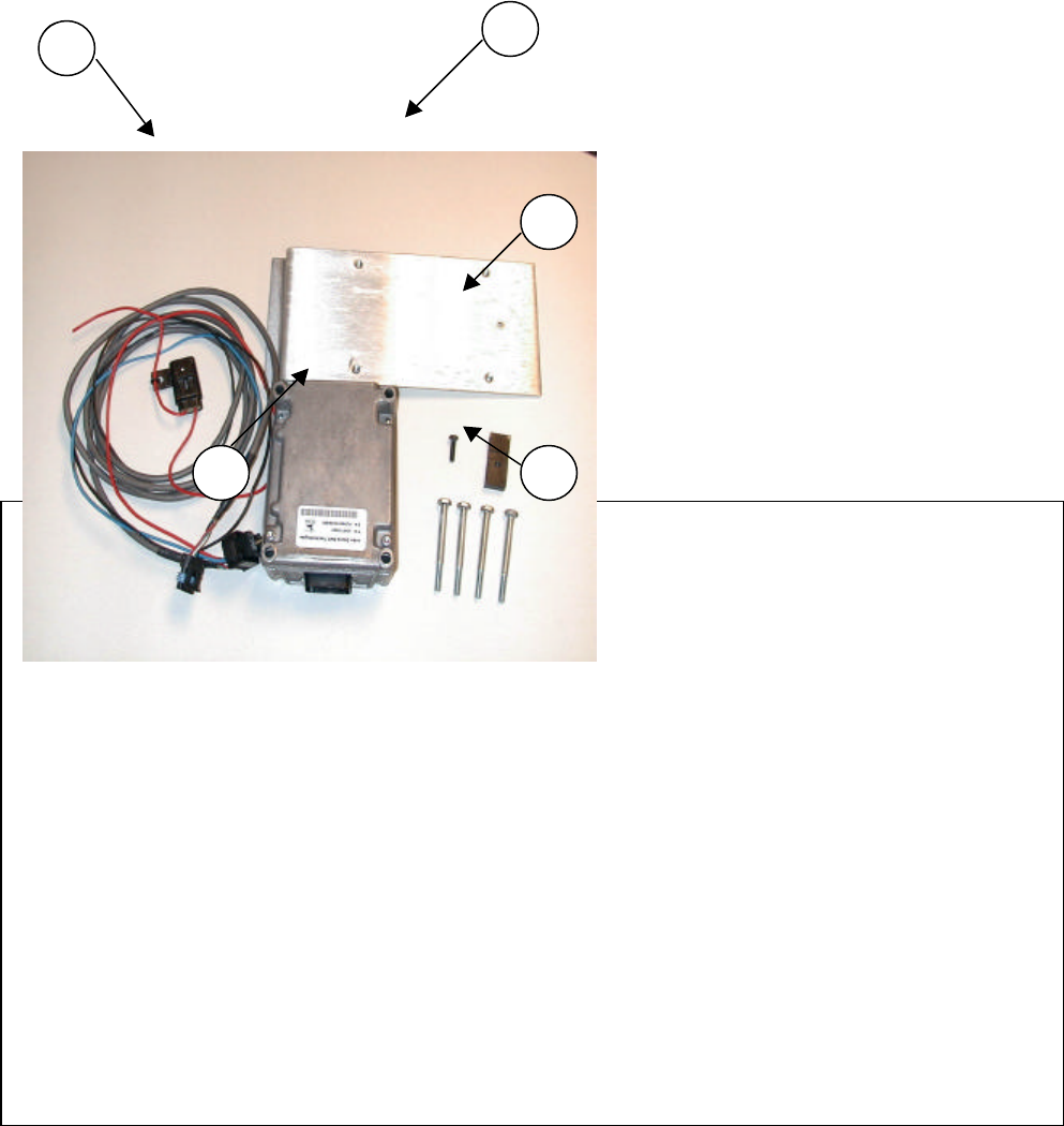
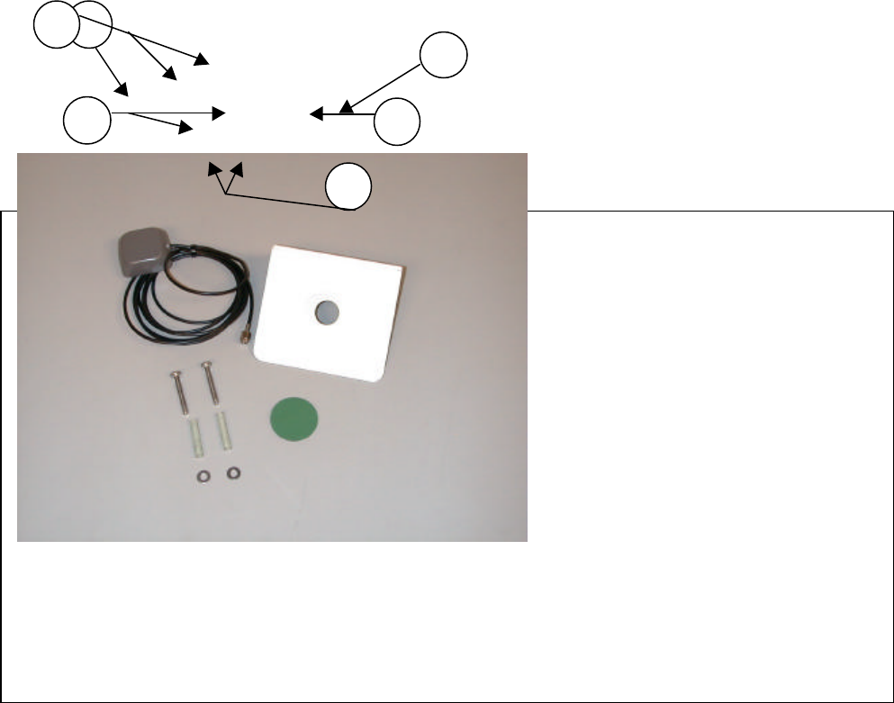
CBL ASSY, CLUBCAR GAS P/N 440-0600 AND POWER SUPPLY
1. Power Harness Assembly
(P/N 440-0660)
2. Power Supply Bracket
(P/N 800-0267)
3. Clamp and screw
(P/N 800-0255 and P/N 812-0067)
4. Bolts
(P/N 816-0006)
5. Power Supply
(P/N JDGT-0002)
1
12
3
45
Installation
SkyLinks (May 00, 2000) Installation Instructions13
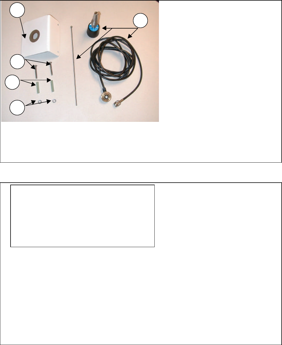
GPS ANT/BKT ASSY CLUBCAR P/N 950-0095 (Pre 2000)
1. GPS Antenna (P/N 496-0002)
2. GPS Bracket (P/N 800-0246)
3. Adhesive Pad (P/N 852-0006)
4. Screws (2) (P/N 812-0068)
5. Washer (2) (P/N 838-0033)
6. Spacer (2) (P/N 840-0111)
1
2
3
4
5
6

Installation
SkyLinks (May 00, 2000) Installation Instructions14
GPS ANT/BKT ASSY CLUBCAR P/N 950-0095 (Post 2000)
1. GPS Bracket
2. GPS Antenna
UHF ANT/BKT ASSY CLUB CAR P/N 950-0094 (Pre 2000)
1. Bracket (P/N 800-0246)
2. Antenna Assembly
(P/N 496-0001)
3. Screws (2) (P/N 812-0068)
4. Washer (2) (P/N 838-0033)
5. Spacers (2) (P/N 840-0111)
A future picture will be inserted of the
GPS bracket, GPS antenna, and
adhesive pad
Installation
SkyLinks (May 00, 2000) Installation Instructions15
UHF ANT/BKT ASSY CLUB CAR P/N 950-0094 (Post 2000)
1. Antenna
2. Antenna whip
3. Bracket
A future picture of the UHF antenna, whip and
bracket will be inserted.
2
1
5
4
3
Installation
SkyLinks (May 00, 2000) Installation Instructions16
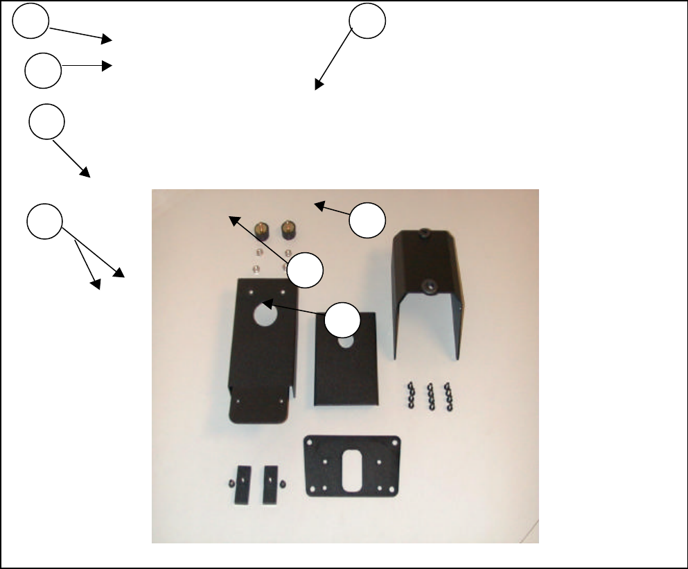
HDWE PKG, CLUB CAR- COLOR P/N 950-0093
1. Bumper (P/N 845-0007)
2. Hex Nut (P/N 822-0025)
3. Center Support (P/N 800-0251)
4. Clamp (P/N 800-0255)
5. Display Unit Plate (P/N 800-0853)
6. Main Bracket (P/N 800-0852)
7. Screws (P/N 812-0066)
8. Support Cover (P/N 800-0251)
1
2
3
4
5
6
7
8

Installation
SkyLinks (May 00, 2000) Installation Instructions17
EZ-GO Sub-Assemblies
CBL ASSY, EZ-GO ELECTRIC P/N XXX-XXXX
1. Power Harness Assembly
A future picture will be inserted of the
power harness with both connectors
labeled.

Installation
SkyLinks (May 00, 2000) Installation Instructions18
CBL ASSY, EZ-GO GAS P/N XXX-XXXX
1. Power Harness Assembly
2. Power Supply Connector
3. Display Unit Connector
A future picture will be inserted of the
power harness with both connectors
labeled.

Installation
SkyLinks (May 00, 2000) Installation Instructions19
GPS ANT/BKT ASSY CLUBCAR P/N XXX-XXXX
1. GPS Bracket
2. GPS Antenna
3. Adhesive Pad
A future picture will be inserted of the GPS
bracket, GPS antenna, and adhesive pad

Installation
SkyLinks (May 00, 2000) Installation Instructions20
UHF ANT/BKT ASSY EZ-GO P/N XXX-XXXX
1. Antenna
2. Antenna whip
3. Bracket
A future picture of the UHF antenna, whip and
bracket will be inserted.

Installation
SkyLinks (May 00, 2000) Installation Instructions21
HDWE PKG, EZ-GO COLOR P/N XXX-XXXX
1. Display bracket
2. Cart Clamps
3. Grommet
4. Grommet
A future picture will be inserted of the
display bracket with important areas
identified.

Installation
SkyLinks (May 00, 2000) Installation Instructions22
Yamaha Sub-Assemblies
CBL ASSY, YAMAHA ELECTRIC P/N XXX-XXXX
1. Power Harness Assembly
2. Power Supply Connector
3. Display Unit Connector
A future picture will be inserted of the
power harness with both connectors
labeled.

Installation
SkyLinks (May 00, 2000) Installation Instructions23
CBL ASSY, YAMAHA GAS P/N XXX-XXXX
4. Power Harness Assembly
5. Power Supply Connector
6. Display Unit Connector
A future picture will be inserted of the
power harness with both connectors
labeled.

Installation
SkyLinks (May 00, 2000) Installation Instructions24
GPS ANT/BKT ASSY YAMAHA P/N XXX-XXXX
1. GPS Bracket
2. GPS Antenna
3. Adhesive Pad
A future picture will be inserted of the GPS
bracket, GPS antenna, and adhesive pad

Installation
SkyLinks (May 00, 2000) Installation Instructions25
UHF ANT/BKT ASSY YAMAHA P/N XXX-XXXX
1. Antenna
2. Antenna whip
3. Bracket
A future picture of the UHF antenna, whip and
bracket will be inserted.

Installation
SkyLinks (May 00, 2000) Installation Instructions26
HDWE PKG, YAMAHA COLOR P/N XXX-XXXX
1. Display bracket
2. Cart Clamps
3. Grommet
4. Grommet
A future picture will be inserted of the display
bracket with important areas identified.

Installation
SkyLinks (May 00, 2000) Installation Instructions27
TOOLS AND EQUIPMENT
Not Supplied With Kit
Club Car Tools and Equipment
Required-Under Review
• 7/16” wrench
• 7/16” socket
• Phillips screwdriver
• Wire Cutters
• Crescent Wrench
• Electric screwdriver/drill
• Phillips head bit
• Socket adapter
• ½ -9/16” socket
• Awl
EZ-GO Tools and Equipment
Required
To be determined
Yamaha Tools and Equipment
Required
To be determined
Installation
SkyLinks (May 00, 2000) Installation Instructions28
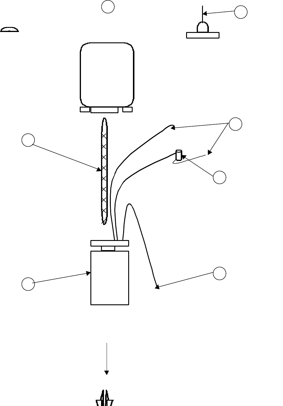
Basic System Layout
3
7
RF Antenna
Display Unit
Power Harness
Battery
Connectors
Fuse Holder
Power supply
Key Switch Connector
2
4
8
6
5

Installation
SkyLinks (May 00, 2000) Installation Instructions29
1-GPS Antenna 4-Power Harness 7-Power Supply
2-RF Antenna 5-Battery Connectors 8-Key Switch connector
3-Display Unit 6-Fuse Holder
Basic Components:
1. Antennas Before Installation review manual. To prevent
2. Display Unit damage to components and cart.
3. Power Supply
4. Power Harness
GPS Antenna
1