Deere and ISG Electronic Systems JDGT-0001 Skylinks Head Unit and Skylinks Power Supply User Manual John Deere Golf Technologies
Phoenix International Corporation Skylinks Head Unit and Skylinks Power Supply John Deere Golf Technologies
Contents
- 1. Instruction Manual Part 1
- 2. Instruction Manual Part 2
- 3. Instruction Manual Part 3
- 4. corrected installation manual
corrected installation manual

John Deere Golf Technologies
Installation Manual
Generation 4
John Deere Golf Technologies
3159 Royal Drive, Suite 320
Alpharetta, GA 30022
1-877-298-8515
Dec 04, 2000

1
Club Car Post 2000
Club Car Post 2000 Club Car Post 2000
Club Car Post 2000 –
––
– Table of Contents
Table of Contents Table of Contents
Table of Contents
Overview
OverviewOverview
Overview ................................
................................................................
................................................................
................................................................
................................................................
................................................................
.......................................
..............
.......2
22
2
Parts List
Parts ListParts List
Parts List................................
................................................................
................................................................
................................................................
................................................................
................................................................
.......................................
..............
.......3
33
3
Assembly Part Numbers ....................................................................................................................................................... 3
Service Part Numbers ........................................................................................................................................................... 5
Parts Included in Bill of Material......................................................................................................................................... 6
Tools and Equipment ............................................................................................................................................................ 9
Basic System Layout
Basic System Layout Basic System Layout
Basic System Layout ................................
................................................................
................................................................
................................................................
.................................................
..................................
.................10
1010
10
Installation Instructions
Installation InstructionsInstallation Instructions
Installation Instructions................................
................................................................
................................................................
................................................................
..............................................
............................
..............11
1111
11
Overview of Club Car Post 2000 UHF Antenna Bracket Installation................................................................. 11
Club Car UHF Post 2000 Bracket Installation ............................................................................................................... 13
Overview of Club Car Post 2000 GPS Antenna Bracket Installation............................................................................. 17
Club Car Post 2000 GPS Bracket Installation................................................................................................................ 18
Overview of Club Car Post 2000 Power Harness Installation......................................................................................... 21
Club Car Power Harness Installation............................................................................................................................... 24
Overview of Club Car Post 2000 Display Unit Bracket Installation............................................................................... 28
Club Car Display Unit Bracket Installation.................................................................................................................... 29
Overview of Generic Display Unit Installation ................................................................................................................. 32
Club Car Display Unit Installation................................................................................................................................... 33
Trouble Shooting
Trouble ShootingTrouble Shooting
Trouble Shooting................................
................................................................
................................................................
................................................................
.........................................................
..................................................
.........................35
3535
35

2
Live With Safety
Please before returning cart to customer, make sure cart is
Functioning properly, especially the safety systems.
Install all safety guards and shields.
Overview
General System
SkyLinks is a golf management / information system. It provides valuable information to the
golfer and the course manager through such technologies as satellite navigation and digital
radio communications.
The main components of SkyLinks are the computer display units on each golf cart, a central
computer server in the clubhouse, workstation computer(s), and a communications system to
tie it all together.
Golf cart computers
The golf cart computer performs the following functions:
Vehicle tracking with GPS (Global Positioning System)
Data feed to/from the clubhouse
oAdvertising images
oText messages from the clubhouse
oDisplay tailored to the golfer to display:
! Course map display
! Accurate yardage information
! Pro's tips

3
Parts List
Assembly Part Numbers
Part numbers are assigned by Phoenix International, and are subject to change without notice
Item Part Number Description
HEAD UNIT ASSEMBLY JDGT-0001 Display Unit
POWER SUPPLY JDGT-0002 Power Supply
BKT, PWR SUPPLY – CLUBCAR 800-0267 Assy with Power Supply
CLAMP, DISPLAY – CLUB CAR 800-0255 Assy with P/N 800-0267 and P/N 950-0093
CBL ASSY, CLUBCAR ELECTRIC 440-0600 Power Harness Assembly
CBL ASSY, CLUBCAR GAS 440-0660 Power Harness Assembly
JDGT HDW KIT JDGT-0004 Bulk Item Hardware Kit
PHMS, PHIL, 10-32 X .750 812-0067 Screw to secure P/N 800-0255
PHMS, PHIL, 10-24 X 1.50 812-0068 Screw to secure P/N 800-0246
PHMS, PHIL, ¼-20 X .500 812-0075 Secures Head Unit
HHMS, CAP ¼-20 X 2.75” 816-0006 Secures Power Supply to bracket
LOCKWASHER, INT, 1/4?” ZNC 832-0019 Assy with P/N 812-0075
WSHR, FLAT #10 SS MS15795 838-0033 Assy with P/N 812-0068
SPCR, CLUBCAR ANTENNA BKT 840-0111 Assy with P/N 800-0246
CABLE TIE, 7.4” STANDARD 850-0005 Secures UHF and GPS Antenna Cables to Cart
CARTON 10 x 6 x 4 900-0053 Box to Hold Bulk Items
POLY BAG, ZIP-LOCK 4 X 6 901-0016 Packaging for shipping
BAG, 10 X 13 2 MIL 901-0022 Packaging for shipping
JDGT HDW KIT JDGT-0013 Bulk Item Hardware Kit
PHMS, PHIL, 10-32 X .750 812-0067 Screw to secure P/N 800-0255
PHMS, PHIL, 10-24 X 1.75 812-0086 Screw to secure P/N 800-0246
PHMS, PHIL, ¼-20 X .500 812-0075 Secures Head Unit
PHMS, PHIL, 10-24 X .312 812-0087 Secures P/N 800-0290 and P/N 800-0292
HHMS, CAP ¼-20 X 2.75” 816-0006 Secures Power Supply to bracket
LOCKWASHER, INT, 1/4?” ZNC 832-0019 Assy with P/N 812-0075
WSHR, FLAT #10 SS MS15795 838-0033 Assy with P/N 812-0068
SPCR, CLUBCAR ANTENNA BKT 840-0111 Assy with P/N 800-0246
CABLE TIE, 7.4” STANDARD 850-0005 Secures UHF and GPS Antenna Cables to Cart
CARTON 10 x 6 x 4 900-0053 Box to Hold Bulk Items
POLY BAG, ZIP-LOCK 4 X 6 901-0016 Packaging for shipping
BAG, 10 X 13 2 MIL 901-0022 Packaging for shipping

4
JDGT BKT/ANT KIT-CLUB GAS JDGT-0011 GEN 4 Club Car Gas Pre 2000 roof
CBL ASSY, CLUBCAR GAS 440-0660 Power Harness Assembly
BKT ASSY, CLUB CAR DSPLY 950-0093 Bracket for Display Unit
UHF ANT/BKT ASSY CLUBCAR 950-0094 UHF RADIO BRACKET ASSEMBLY PRE 2000
CLAMP, DISPLAY – CLUB CAR 800-0255 Assy with P/N 800-0267 and P/N 950-0093
CRTN, 22 5/16 X 18 3/16 X 900-0001 Packaging for shipping
PARTITION, 35 CELL 900-0006 Packaging for shipping
BUBBLE WRAP, ANT-STATIC 903-0001
BKT ASSY, CLUB CAR DSPLY 950-0093 Bracket for Display Unit
Cover, Support – Club Car 800-0250 Cover Support Display
Support, Center –Club Car 800-0251 Center Support Display
BKT, MTG – Club Car 800-0852 Mounting Bracket Display
Plate, MTG – Color DSPLY 800-0853 Mounting Plate Display
PHMS, PHIL, 10-32 x .375 812-0066
Hex Nut, 1/4 –20 Jam 18-8 822-0025 Secures P/N 845-0007
Bumper, 1” OD ¼ -20 x .50 845-0007 Attaches to Center Support
Grommet, Neoprene ID=5/16 845-0007
Grommet, Neoprene ID=1/2 881-0009
Antenna, GPS 8ft SMA MAG 496-0002 GPS Antenna
BKT, Antenna – Club Car 800-0246 Bracket for Antenna
Pad, Antenna MTG – PSC 852-0006 Adhesive for Antenna
BKT, Ant GPS Club Car 2000 800-0291 Bracket for GPS Antenna Post 2000
UHF ANT/BKT ASSY CLUB 2K 950-0106 UHF BRACKET ASSEMBLY POST 2000
Antenna, UHF Maxrad 496-0006 UHF Antenna
BKT, Ant UHF Club 2k 800-0290 Top Piece of Post 2000 UHF Antenna
PHMS, PHIL 10-24 X 1.75 812-0086 Secures P/N 800-0290 and P/N 800-0292
BKT, Ant-Bottom Club 2000 800-0292 Bottom Piece of Post 200 UHF antenna

5
Service Part Numbers
Service part numbers may be different from Bill of Material part numbers.
Part numbers are assigned by Phoenix International, and are subject to change without notice.
Item Part Number Description
ANTENNA, GPS 8ft SMA MAG 496-0002 GPS antenna
ANTENNA, UHF Maxrad 496-0006 UHF Antenna
CBL ASSY, CLUBCAR ELECTRIC 440-0600 Power Harness Cable
CBL ASSY, CLUBCAR GAS 440-0660 Power Harness Cable
DISPLAY UNIT JDT-0001 Display
FUSE 3A, AUTO BLADE VI0 861-0054 3-amp fuse
GPS ANT/BKT ASSY CLUB CAR 800-0291 GPS bracket for Club Car Post 2000
HDWE PKG, CLUB CAR- COLOR 920-0017 Head Unit Bracket Assembly
PAD, ANTENNA MTG – PSC 852-0006 Circular adhesive for GPS Ant
POWER SUPPLY JDGT-0002 Wedge Box
UHF ANT/BKT ASSY CLUBCAR 496-006 UHF bracket for Club Car Post 2000

6
Parts Included in Bill of Material
There are different parts numbers for the Power Harness, GPS Antenna Bracket, and UHF Antenna Bracket
based on the specific cart model and year.
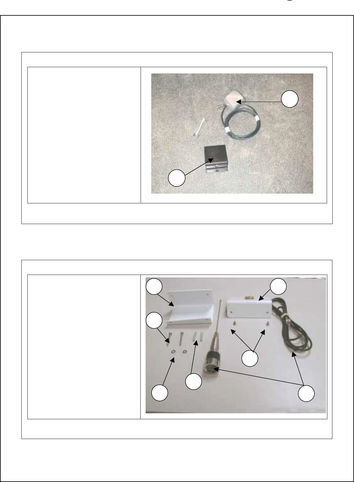
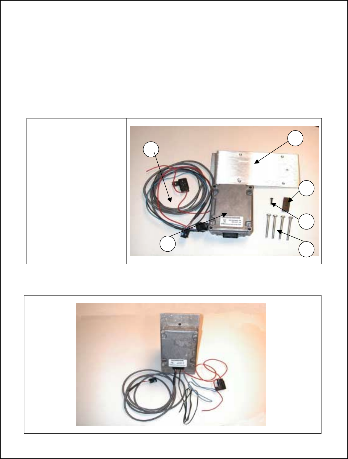
Club Car Sub-Assemblies
CBL ASSY, CLUBCAR ELECTRIC P/N 440-0600 AND POWER SUPPLY
1. Power Harness Assembly
(P/N 440-0660)
2. Power Supply Bracket
(P/N 800-0267)
3. Clamp and screw
(P/N 800-0255 and P/N 812-0067)
4. Bolt
(P/N 816-0006)
5. Power Supply
(P/N JDGT-0002)
CBL ASSY, CLUBCAR GAS P/N 440-0660 AND POWER SUPPLY
1. Power Harness Assembly
(P/N 440-0660)
2. Power Supply Bracket
(P/N 800-0267)
3. Clamp and screw
(P/N 800-0255 and P/N 812-0067)
4. Bolt
(P/N 816-0006)
5. Power Supply
(P/N JDGT-0002)
1
1 2
3
4 5
1
2
3
45
7
GPS ANT/BKT ASSY CLUBCAR P/N 950-0095 (Post 2000)
1. GPS Bracket
(P/N 800-0291)
2. GPS Antenna
(P/N 496-0002)
UHF ANT/BKT ASSY CLUB CAR P/N 950-0094 (Post 2000)
1. Antenna bracket bottom
(P/N 800-0292)
2. Antenna bracket top
(P/N 800-0290)
3. Antenna
(P/N 496-0006)
4. Screws to attach brackets
(P/N 812-0086)
5. Sheathing
(P/N 840-0111)
6. Washer
(P/N 838-0033)
7. Mounting screws
(P/N 812-0068)
1 2
3
4
5
6
7
1
2
8
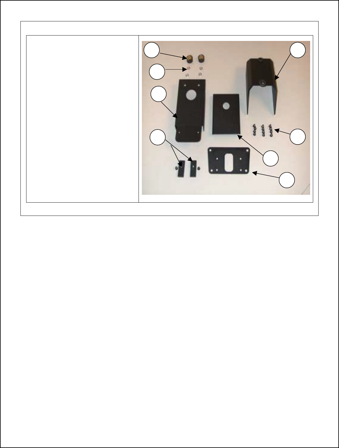
HDWE PKG, CLUB CAR- COLOR P/N 950-0093
1. Bumper (P/N 845-0007)
2. Hex Nut (P/N 822-0025)
3. Center Support (P/N 800-0251)
4. Clamp (P/N 800-0255)
5. Display Unit Plate (P/N 800-0853)
6. Main Bracket (P/N 800-0852)
7. Screws (P/N 812-0066)
8. Support Cover (P/N 800-0251)
1
2
3
4
5
6
7
8

9
Tools and Equipment
Not Supplied With Kit
Club Car Tools and Equipment
Required-Under Review
! Crescent Wrench
! Electric Screwdriver/Drill
! Phillips Head Bit
! Phillips Screwdriver
! Socket Adapter
! Wire Cutters
! ½ -9/16” Socket
! 7/16” Socket
! 7/16” Wrench
! ½” Nut driver
! 3/8” Nut driver
! 5/16” Nut driver
10
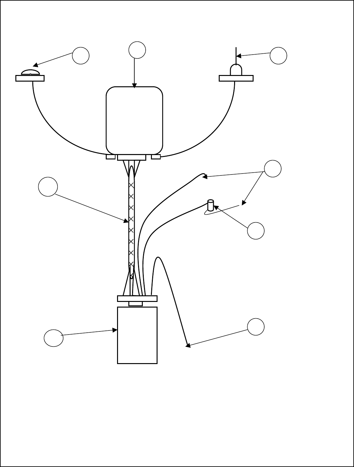
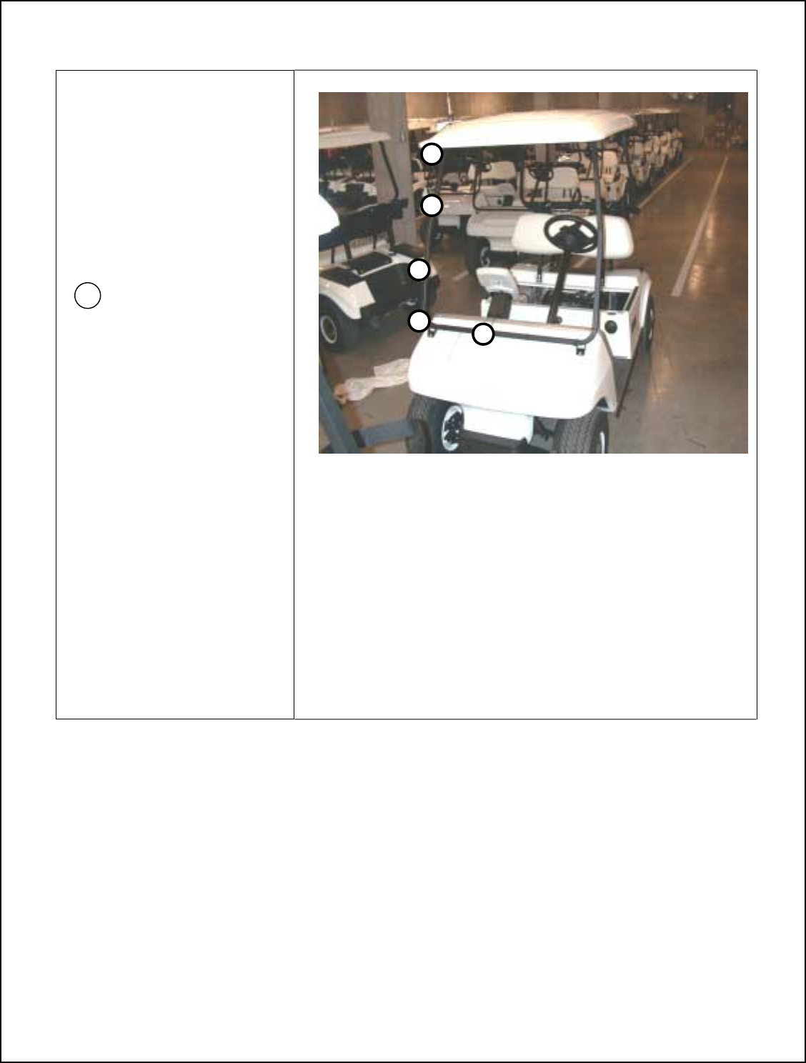
Basic System Layout
1-GPS Antenna 4-Power Harness 7-Power Supply
2-RF Antenna 5-Battery Connectors 8-Key Switch connector
3-Display Unit 6-Fuse Holder
Basic Components:
1. Antennas Before Installation review manual. To prevent
2. Display Unit damage to components and cart.
3. Power Supply
4. Power Harness
3
7
GPS Antenna RF Antenna
Display Unit
Power Harness
Battery
Connectors
Fuse Holder
Power supply
Key Switch Connector
2
4
8
6
1
5

11
Installation Instructions
Overview of Club Car Post 2000 UHF Antenna Bracket Installation
FCC Antenna Radiation Caution to Installers
Use of any antenna other than the one provided with this kit may expose the user to radio frequency
(RF) emission levels outside the FCC safety guidelines.
IMPORTANT NOTE: To comply with FCC RF exposure requirements, the following antenna
installation and device-operating configuration must be followed to ensure a separation distance of
20 cm between the antenna and the operators of the golf cart
! Left (drivers side) and Right side of cart will be identified as someone sitting forward in cart.
! Before doing any work on golf cart, make sure that the key is in the off position.
! Ensure the parking brake is set.
! Remove windshields if installed before beginning as per Cart Manufacture User’s Manual.
! The UHF antenna cable is not attached to the Display Unit during this phase of the installation. Leave
cable assemble available for easy access for latter in the installation.
Specific UHF Antenna Bracket Installation instructions per cart type (ex. Club Car, EZ-GO, Yamaha), and
model.
12
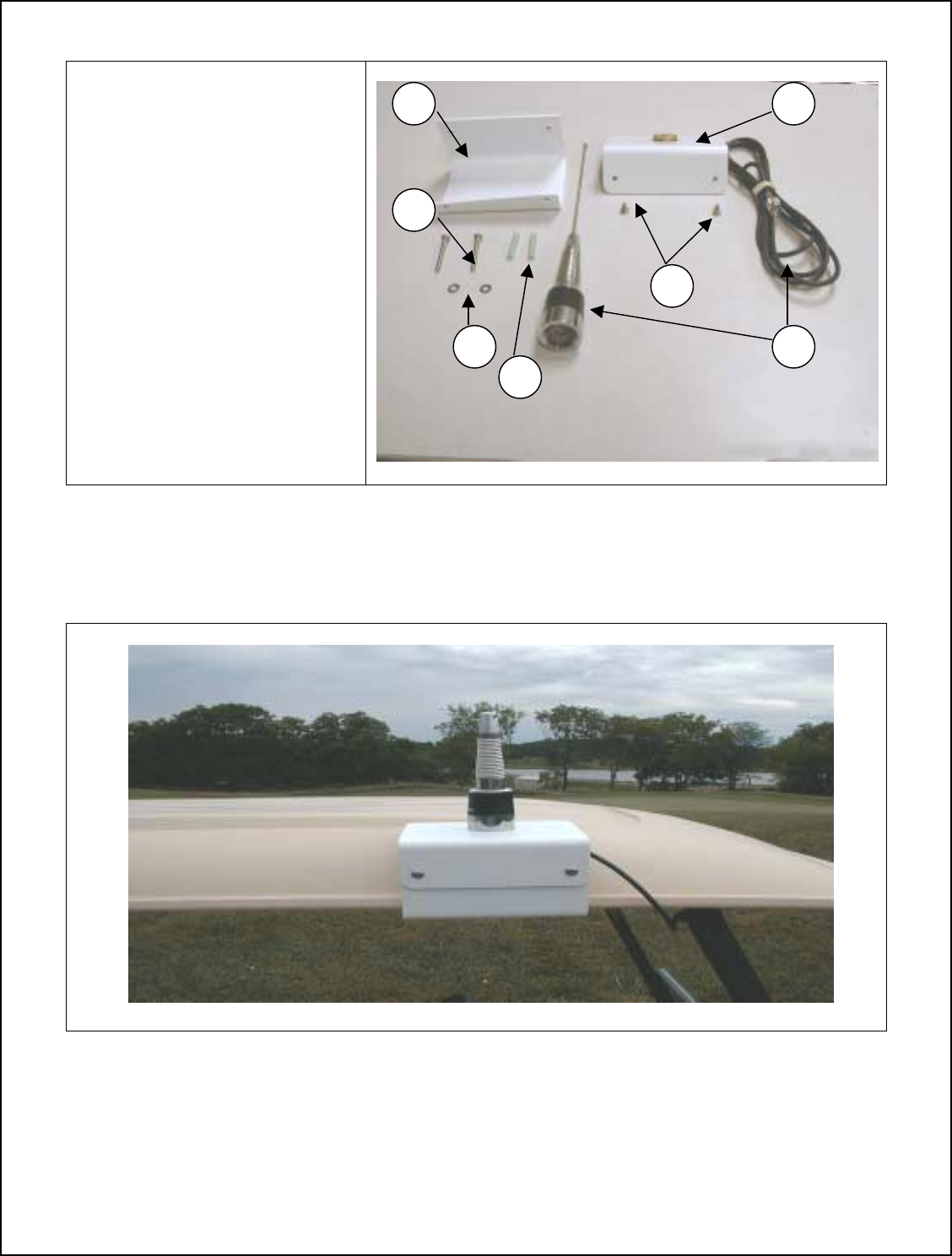
Club Car Post 2000 UHF Antenna Bracket Installation Parts (P/N 950-0106)
1. Antenna Bracket Bottom
(P/N 800-0292)
2. Antenna Bracket Top
(P/N 800-0290)
3. Antenna
(P/N 496-0006)
4. Securing bracket screws
(P/N 812-0086)
5. Spacer
(P/N 840-0111)
6. Phillips Screws (2)
(P/N 812-0086)
7. Flat Washer (2)
(P/N 838-0033)
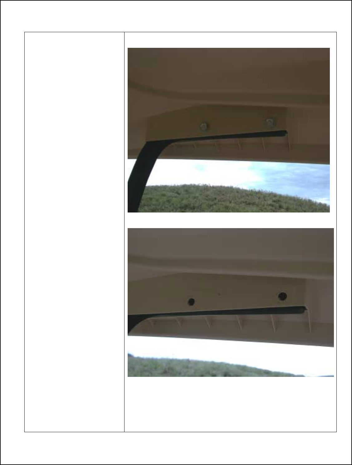
Club Car Post 2000 Completed UHF Bracket Installation
1 2
3
4
5
7
8
13
Club Car UHF Post 2000 Bracket Installation
1. Remove right side 7/16
bolts securing roof
.
Note: save 7/16 bolts and
nuts for de-installation.
14
3. Attach top half of
antenna bracket with
screws and lock
tight.
Note: Use Part Numbers:
800-0290 top half of bracket
812-0086 screws
2. Attach screw, washer and
plastic sheathing to bracket,
and secure
Important:
UHF bracket
needs to be isolated from
cart ground.
Note: Use Part Numbers:
840-0111 spacer
838-0033 washer
812-0086 screw
800-0292 bottom half of
bracket
15
4. Attach Antenna
cable to bracket.
5. Attach antenna whip
to cable base.
Note: Use Part Number:
496-0006 antenna assy.
Caution
The installer(s) must
follow the antenna
installation procedure set
fourth in this manual to
insure that while the
device is in operation, a
separation of at least 20
cm is maintained between
antenna and the user.
These instructions must
be followed in order to
meet the FCC RF
exposure guidelines.
These requirements can
only be met if the antenna
is installed as described
in the installation
procedure steps and
depicted in the pictures of
the antenna location and
mounting bracket
16
6. Route UHF antenna cable
down roof support. Placing the
first tie strap at the top bend of
support, and another every 6-8
inches.
Important: Do not pull UHF
cable tight at the roof
location. Allow a gentle bend
to cart frame.
= Zip tie location
6. This completes the UHF
bracket and UHF cable
installation.
Note: Leave UHF cable
connector end unattached. It
will be connected latter in the
installation.
17
Overview of Club Car Post 2000 GPS Antenna Bracket Installation
! Left (drivers side) and Right side of cart will be identified as someone sitting forward in cart.
! Before doing any work to the golf cart, make sure the key is in the off position.
! Ensure the parking brake is set.
! Remove windshields if installed before beginning installation as per Cart Manufacture User’s Manual.
! The GPS antenna cable is not attached to the Display Unit during this phase of the installation. Leave
cable assemble available for easy access for latter in the installation.
Specific GPS Antenna Bracket Installation instructions per cart type ex. (Club Car, EZ-GO, Yamaha) and Model
type.
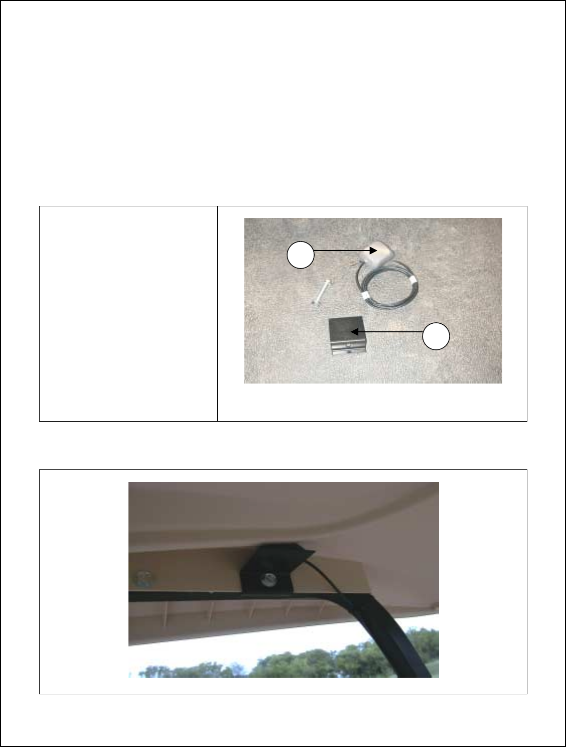
Club Car Post 2000 GPS Antenna Bracket Installation Parts
1. GPS Antenna
(P/N 800-0291)
2. GPS Bracket
(P/N 496-0002)
Club Car Completed Post 2000 GPS Bracket Installation
1
2
18
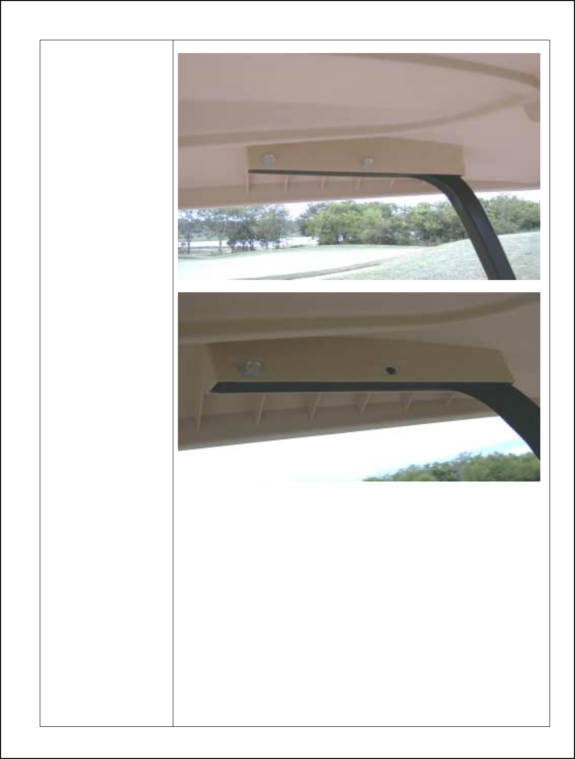
Club Car Post 2000 GPS Bracket Installation
1. Remove front
7/16 bolt with
locking nut on left
side.
19
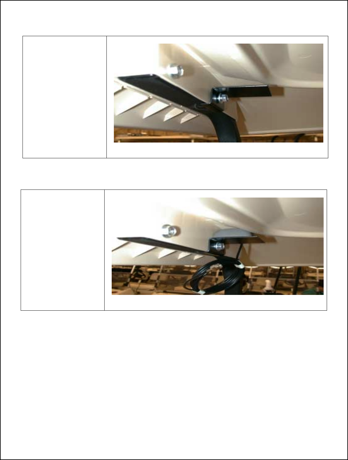
3. Mount GPS antenna
on bracket. Antenna
attaches magnetically.
Note: Use Part Number:
800-0291 GPS Antenna
2. Mount GPS antenna
bracket with 7/16 bolt
that was removed in step
1, and reattach.
Note: Use Part Number:
496-0002 GPS Bracket
20
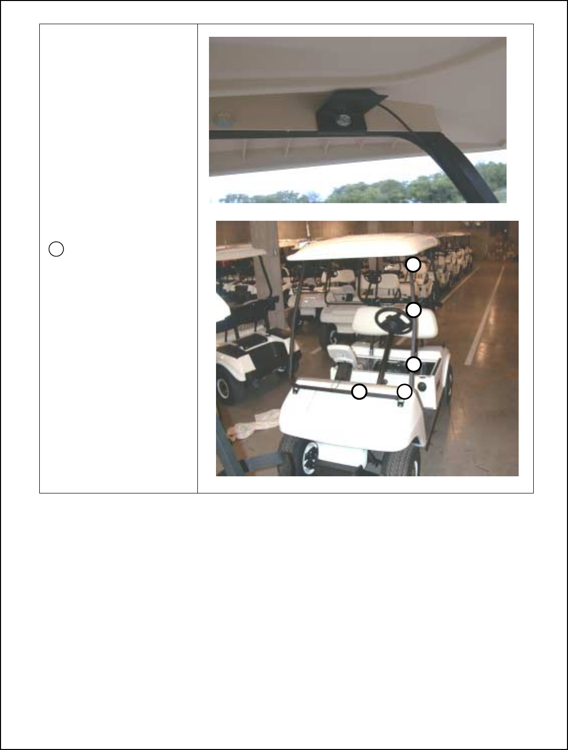
3. Route GPS antenna cable
down roof support. Placing
the first tie strap at the top
bend of support, and another
every 6-8 inches.
Important: Do not pull
GPS cable tight at the roof
location. Allow a gentle
bend to cart frame.
= Zip tie location
4. This completes the GPS
bracket and GPS cable
installation.
Note: Leave GPS cable
connector end unattached.
It will be connected latter in
the installation.
21
Overview of Club Car Post 2000 Power Harness Installation
• Make sure key switch is in the off position.
• Use caution when working around the batteries. Battery acid may exist around the terminal area.
• Verify the positive lead and ground of cart.
• When routing the Power Harness cable make sure the cable does not interfere with cart operation.
• The cable should be isolated of working parts of the cart.
• Two installers are required to remove seat to avoid back injuries.
Parts Required for Assembly of Power Supply Bracket and Mounting Power Supply
1. Power Harness
Electric (P/N 440-0600)
Gas (P/N 440-0660)
2. Power Supply Bracket
(P/N 800-0267)
3. Clamp
(P/N 800-0255)
4. Phillip Head Screw
(P/N 812-0067)
5. Bolt (4)
(P/N 816-0006)
6. Power Supply
(P/N JDGT-0002)
Club Car Power Harness Installation Parts
2
3
5
6
1
4
22
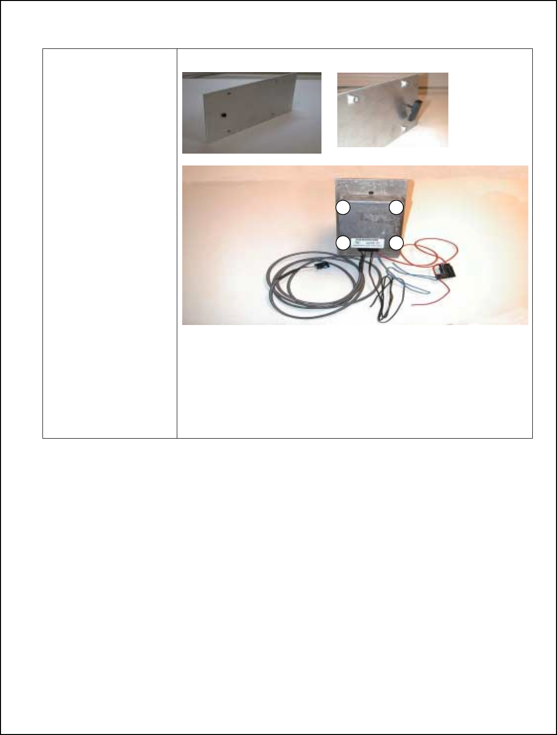
Assembly of Power Supply Bracket and Mounting Power Supply
1. Insert screw into
hole on flat side of
Power Supply
Bracket
2. Start screw into
clamp
Note: Use Part Numbers:
P/N 800-0255 clamp
P/N 812-0067 screw
Note: Notch of clamp
should be to the inside
towards power supply
bracket.
3. Mount Power
Supply onto bracket
using four bolts.
Note: Power Supply
connector should be
facing towards beveled
end of power supply
bracket.
Note: Use Part Numbers:
P/N 816-0006 bolts
P/N JDGT-0002 Power
Supply
P/N 440-0600 electrical
P/N 440-0660 gas
P/N 800-0267 bracket
23
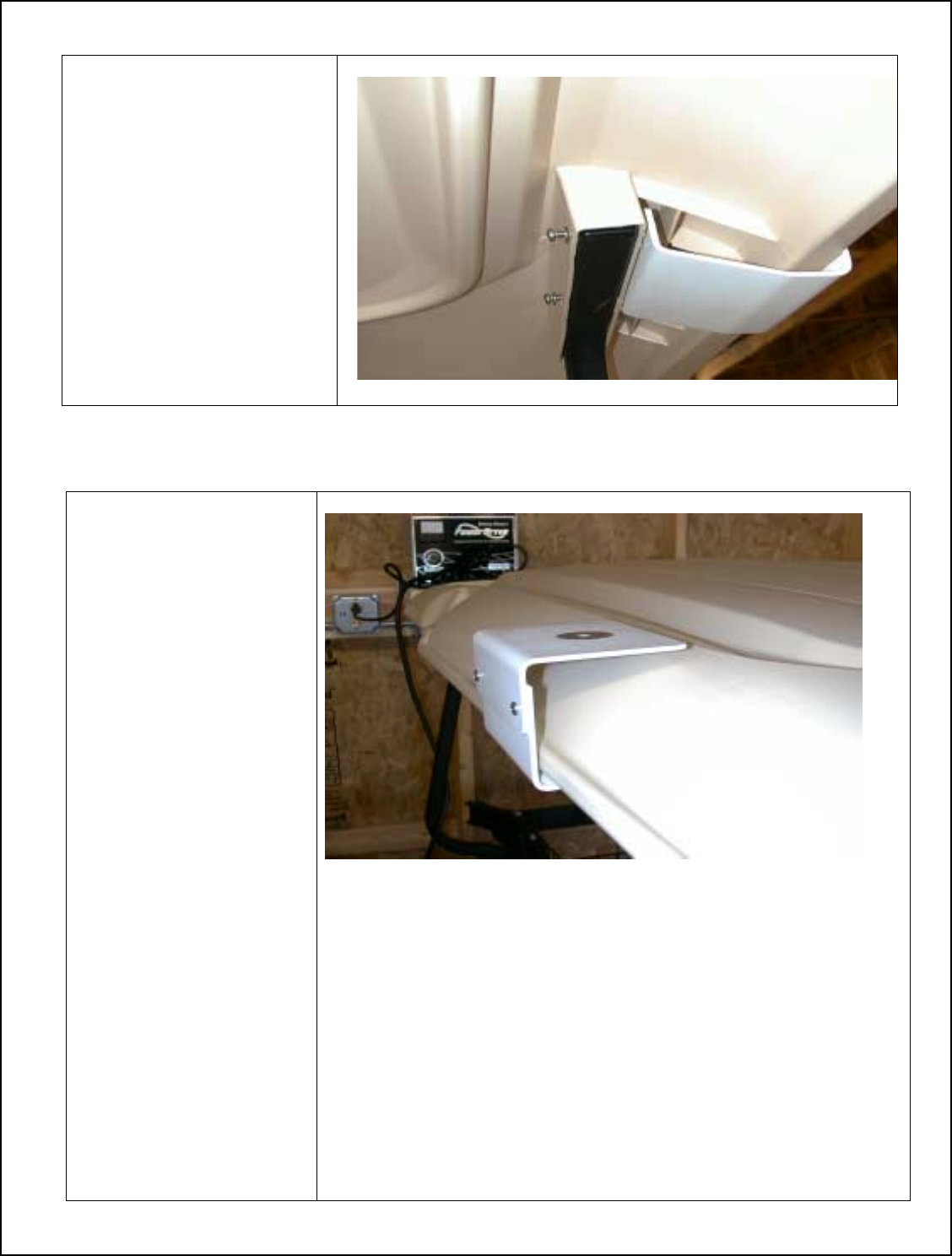
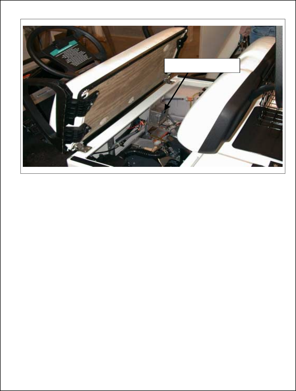
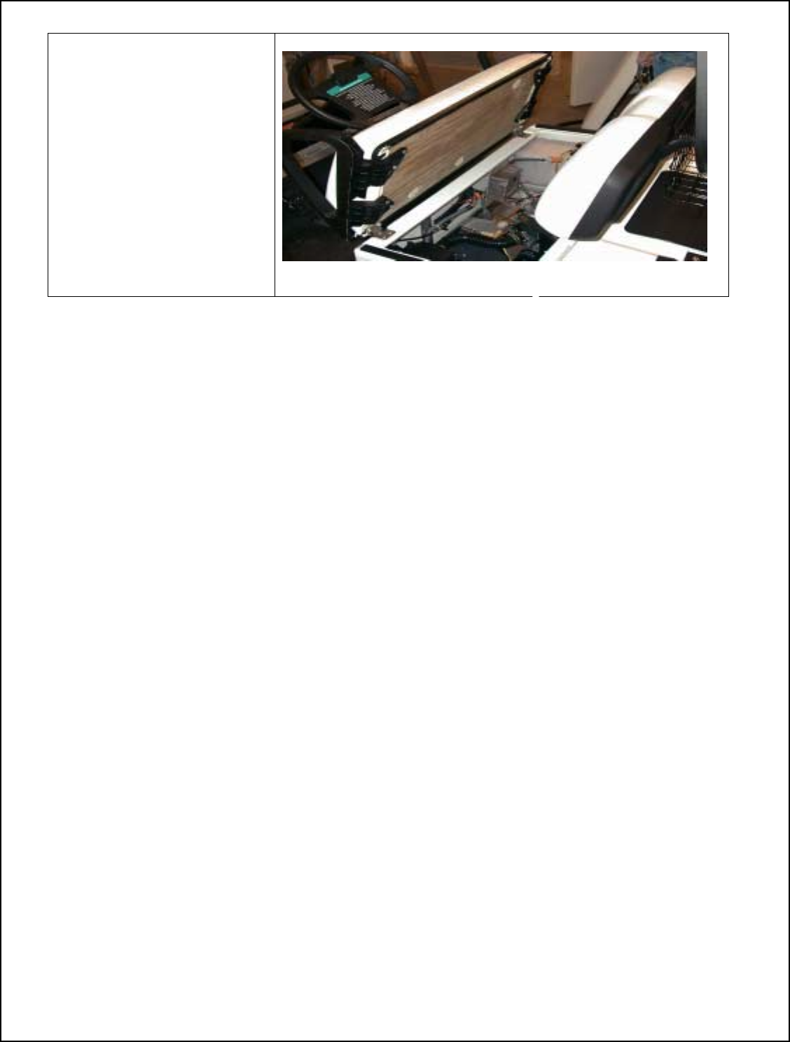
Club Car Completed Power Harness Installation
Power Supply Location
24
Club Car Power Harness Installation
Note: Two Persons Should
be used to Remove Seat.
1. Remove Seat
2. Mount Power Supply
Bracket to cart.
Location is left side
3. Tighten screw for
Wedge
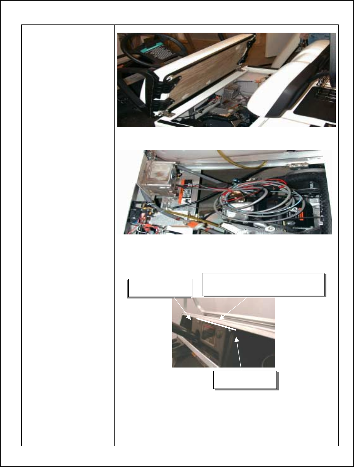
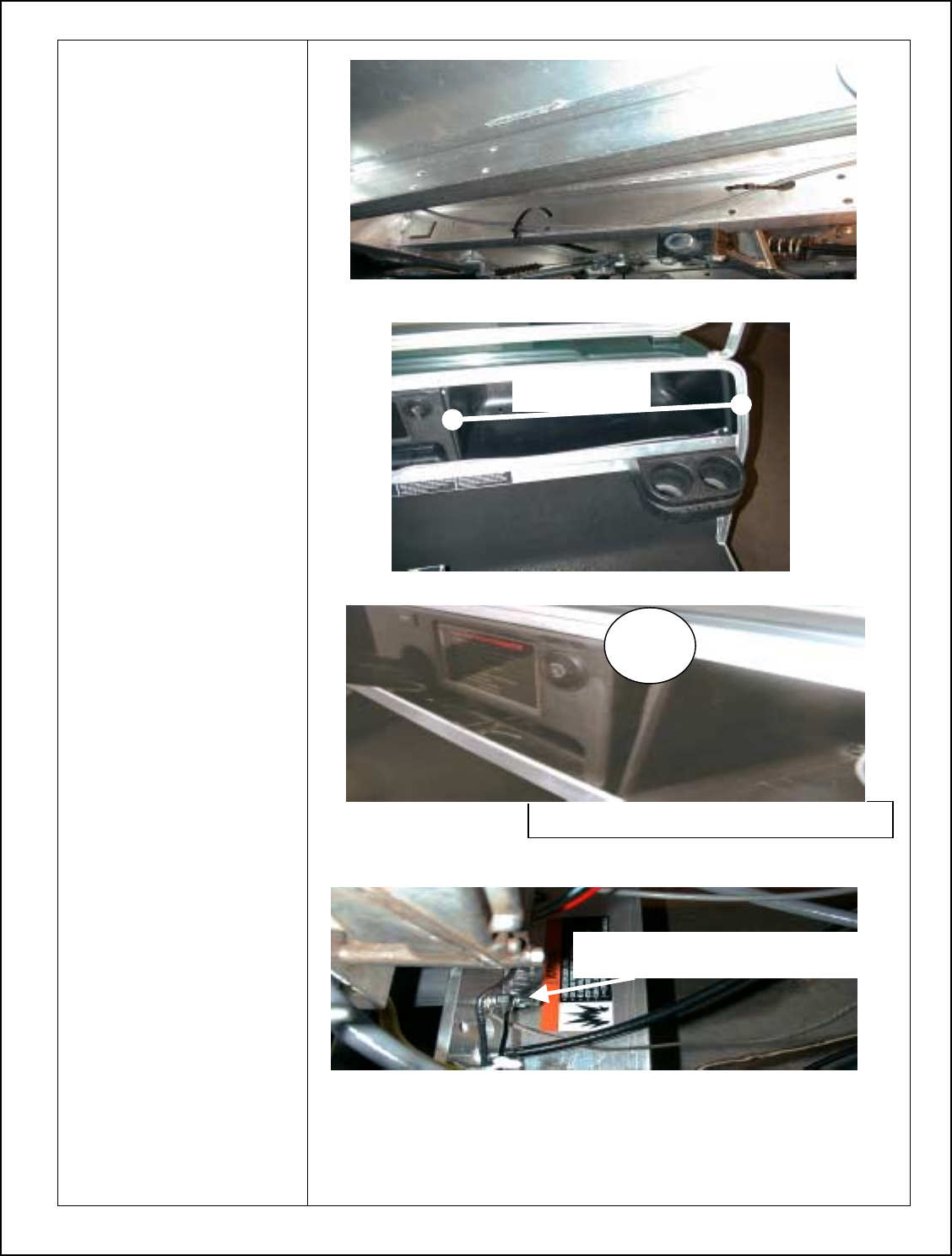
4. Remove Dash
Note: Use Steps 5 through
18
5. Remove screw caps
on the side of
dashboard, and save
6. Loosen screws
securing dashboard
7. Pop off top of
dashboard by running
screwdriver along the
top of dash and below
frame of cart
8. Bend top right corner
of dash inward to get
key switch assembly
out of dash
Note: DO NOT LET KEY
SWITCH COME IN CONTACT
WITH FRAME OF CART. IT
WILL BLOW THE FUSE TO
THE CART.
9. Run screwdriver along
bottom side of
dashboard to finish
removing
10. Clip a ½” x ½” notch in
the lower right corner
of the dashboard.
Note: This is to allow
enough clearance for the
power cable to be ran into
the bracket and attach to
the head unit.
A. Remove cap
B. Loosen scre
w
E. Insert screwdriver here to remove dash.
F. Run screwdriver along black line
C. Remove cap
D. Loosen scre
w
25
11. Route Power cable
along frame of cart.
Secure with tie straps.
In predrilled holes.
12. Pull about 1’ 6” of
cable out to be ran for
the Display Unit.
Installation Tip:
Run power cable to corner
of compartment.
13. Insert bottom of
dashboard back into
place
Note: BE CAREFUL NOT TO
ALLOW THE KEYSWITCH
TO COME IN CONTACT
WITH THE CART FRAME.
14. Bend right corner
inward to allow key
switch room to be
inserted
15. Place left corner in
place
16. Push top part of dash
into place
17. Tighten screws
18. Replace caps
19. Attach Black wire to
cart ground and
secure with 5/16” lock
washer 5/16” nut.
20. Route Red and Blue
wire. Securing with tie
straps.
Note: The cable should be
isolated of working parts of
the cart.
Bend corner inward to get key switch past frame
Cable Length
Car
t
Ground Connection
26
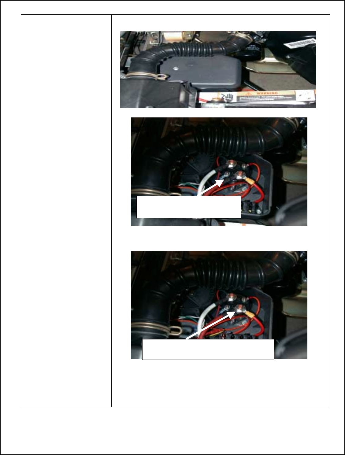
21. Remove Electrical
Component Box
Cover with 3/8” nut
driver.
22. Remove Nut securing
cart’s blue wire
23. Install blue wire to
electrical system for
key switch.
24. Reinstall nut securing
both blue key switch
wires.
25. Remove Nut securing
red battery lead on
solenoid with ½” nut
driver.
26. Attach red wire to
solenoid post.
27. Reinstall nut securing
red wire and red
battery lead with nut.
28. Tighten with ½” nut
driver.
Blue wire for key switch
connection.
Nut securin
g
red wire on solenoid
27
29. Secure fuse holder to cart
with tie strap.
Note: Make Sure Fuse
Holder is in a Vertical
Position with Leads
Facing Toward the
Ground, and the Fuse
Holder is Accessible
30. Replace the Seat
28
Overview of Club Car Post 2000 Display Unit Bracket Installation
• Left (drivers side) and Right side of cart will be identified as someone sitting forward in cart.
• Make sure key switch is in the off position.
• Ensure the parking brake is set.
• When routing the Power Harness cable make sure the cable does not interfere with cart operation.
• The cable should be isolated of working parts of the cart.
Specific Display Unit Bracket Installation instructions per cart type ex. (Club Car, EZ-GO, Yamaha)
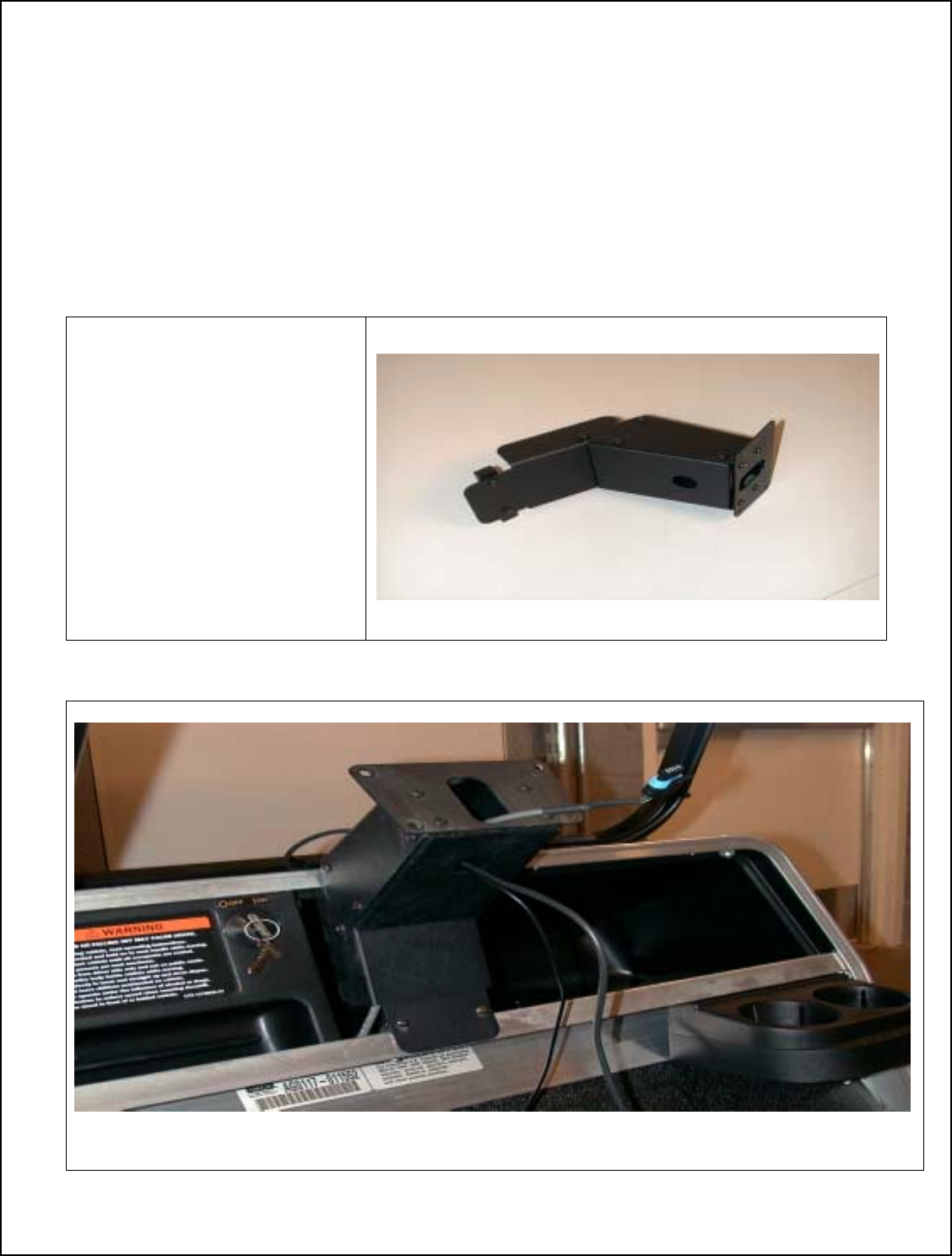
Club Car Display Unit Bracket Installation Parts
1. Display Unit Bracket
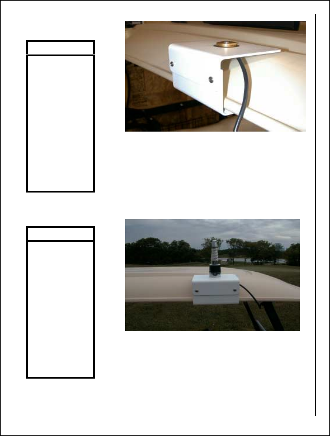
Club Car Completed Display Unit Bracket Installation
.
29
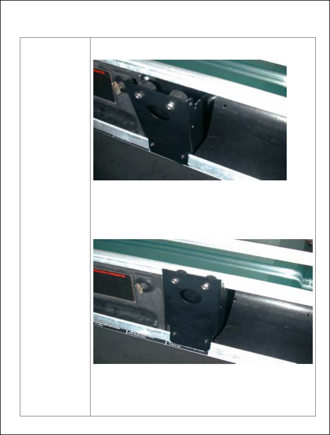
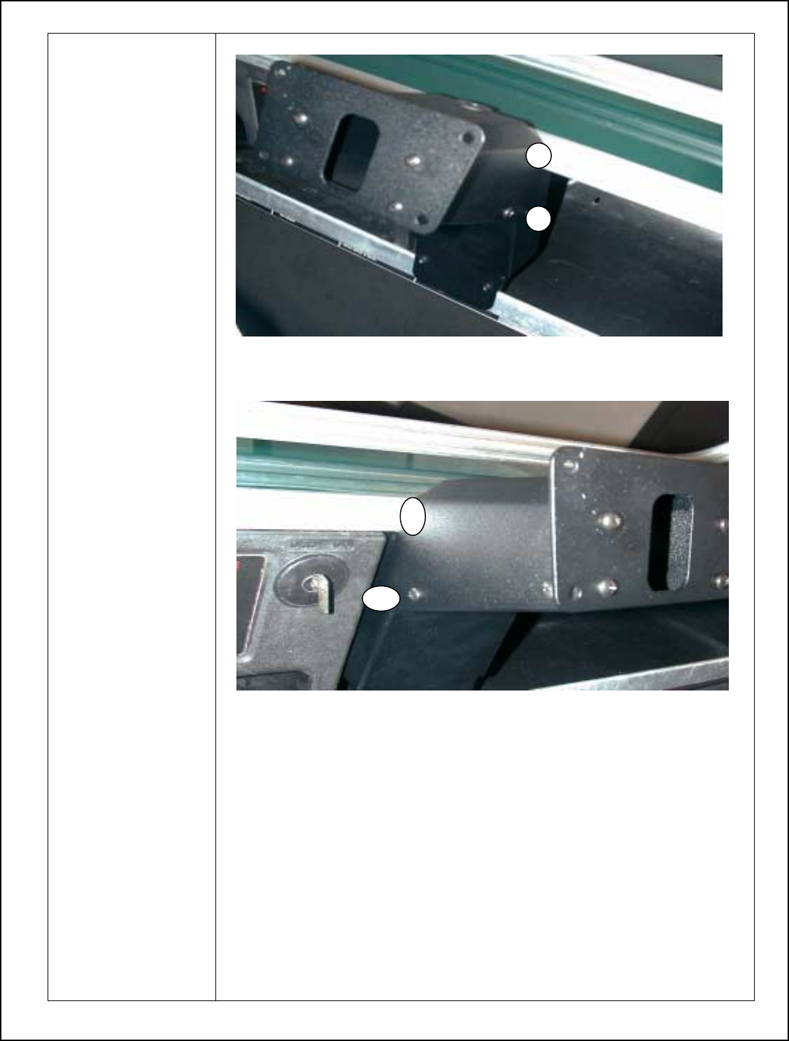
Club Car Display Unit Bracket Installation
1. Install Mounting
Bracket on left
side of cart.
Note: Place
bracket as close to
dash as possible.
2. Push bracket up
until ridge of
bracket inserts
under lip of cart.
Also ensure the
lower wedge
pieces are
positioned
correctly.
Note: Wedge
pieces should be
aligned so the
notch sits properly
to cart edge.
30
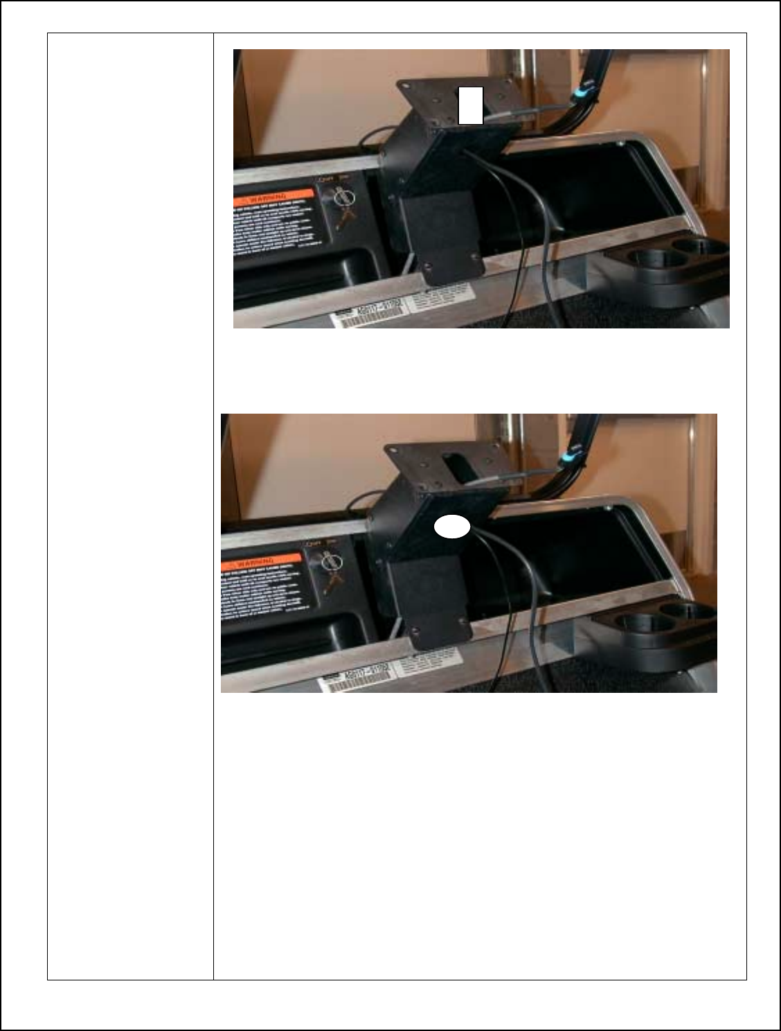
3. Install
centerpiece to
bracket. Secure
with four
screws.
31
4. Run Power
Harness cable
behind
mounting
bracket and into
hole in center
piece of display
bracket.
5. Route GPS and
UHF cables
through the
center hole of
center support.
32
Overview of Generic Display Unit Installation
• Left (drivers side)and Right side of cart will be identified as someone sitting forward in cart.
• Make sure key switch is in the off position.
• Ensure the parking brake is set.
• When routing the Power Harness cable make sure the cable does not interfere with cart operation.
• The cable should be isolated of working parts of the cart.
• Use caution when installing the UHF and GPS connectors to the Display Unit.
Specific Display Unit Bracket Installation instructions per cart type ex. (Club Car, EZ-GO, Yamaha)
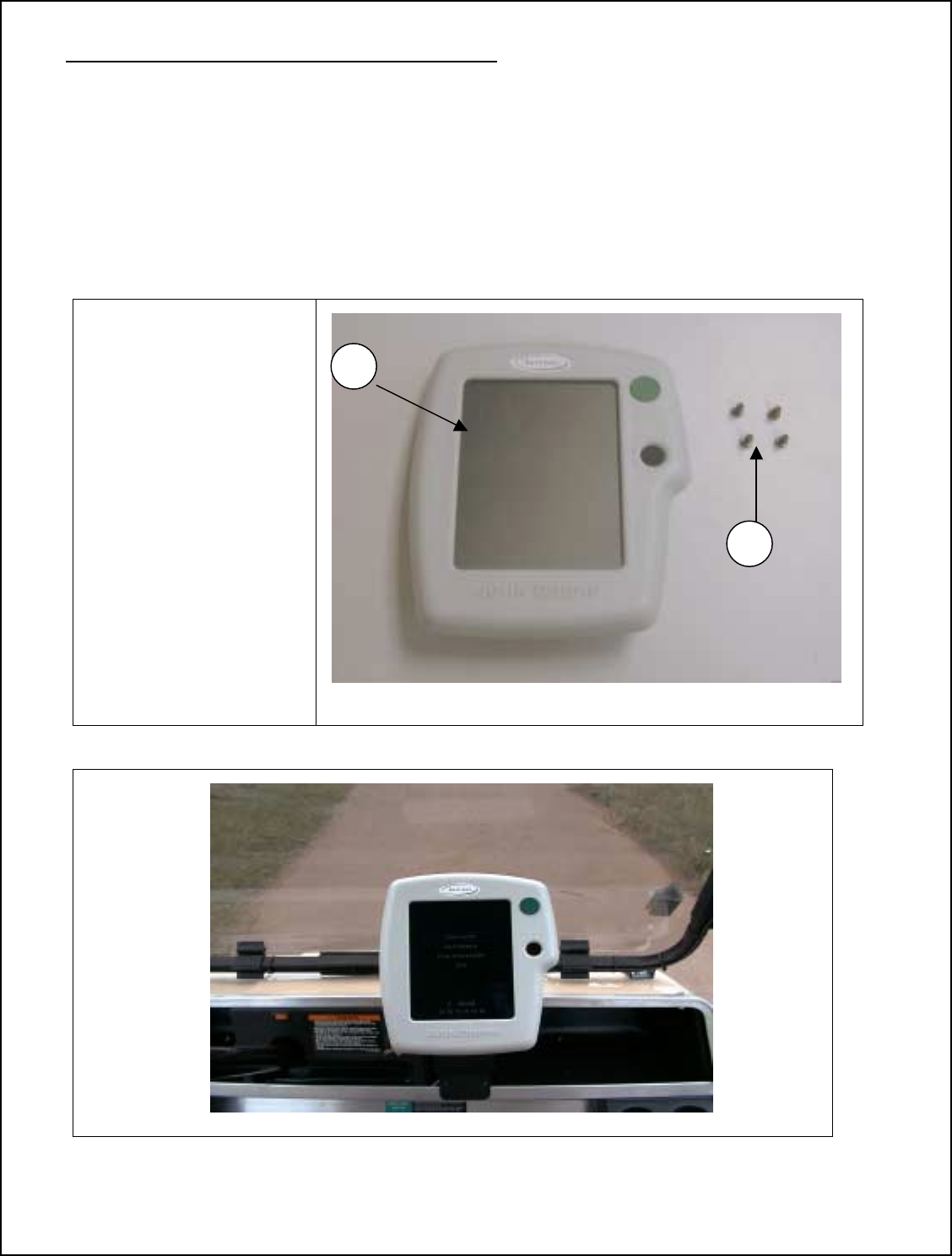
Club Car Display Unit Installation Parts
1. Display Unit
P/N JDGT-0001
2. Screws (4)
P/N 812-0075
Club Car Display Unit Installation
1
2
33
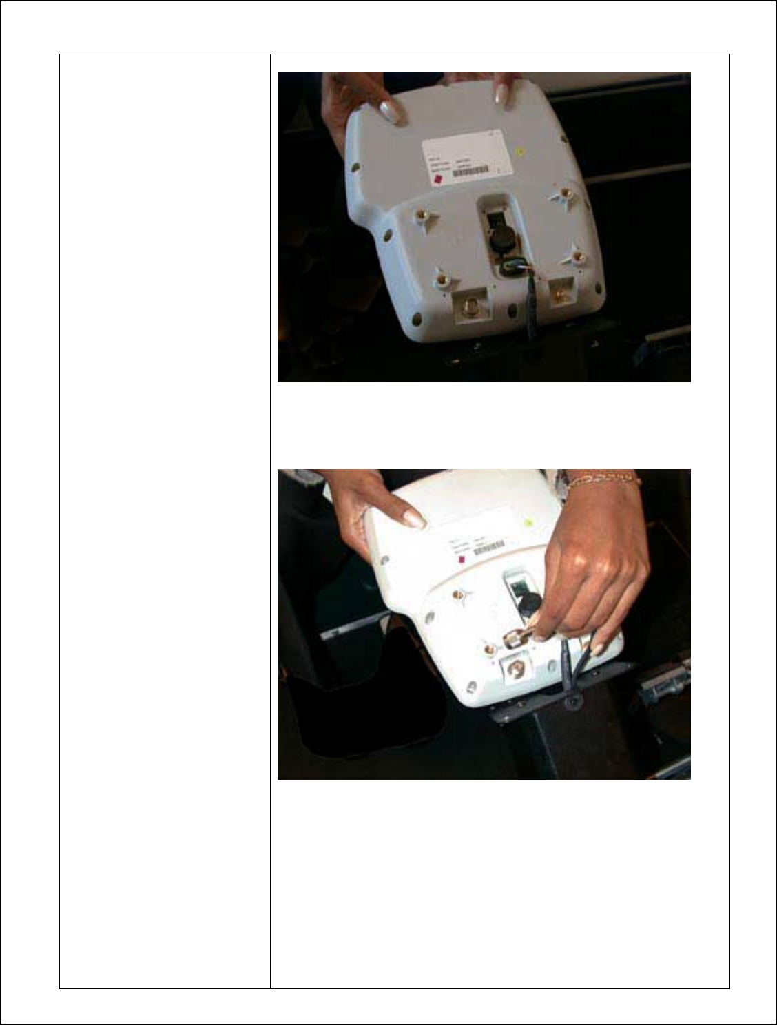
Club Car Display Unit Installation
1. Connect Power
Harness connector to
Display Unit
2. Attach UHF Connector
to Display Unit
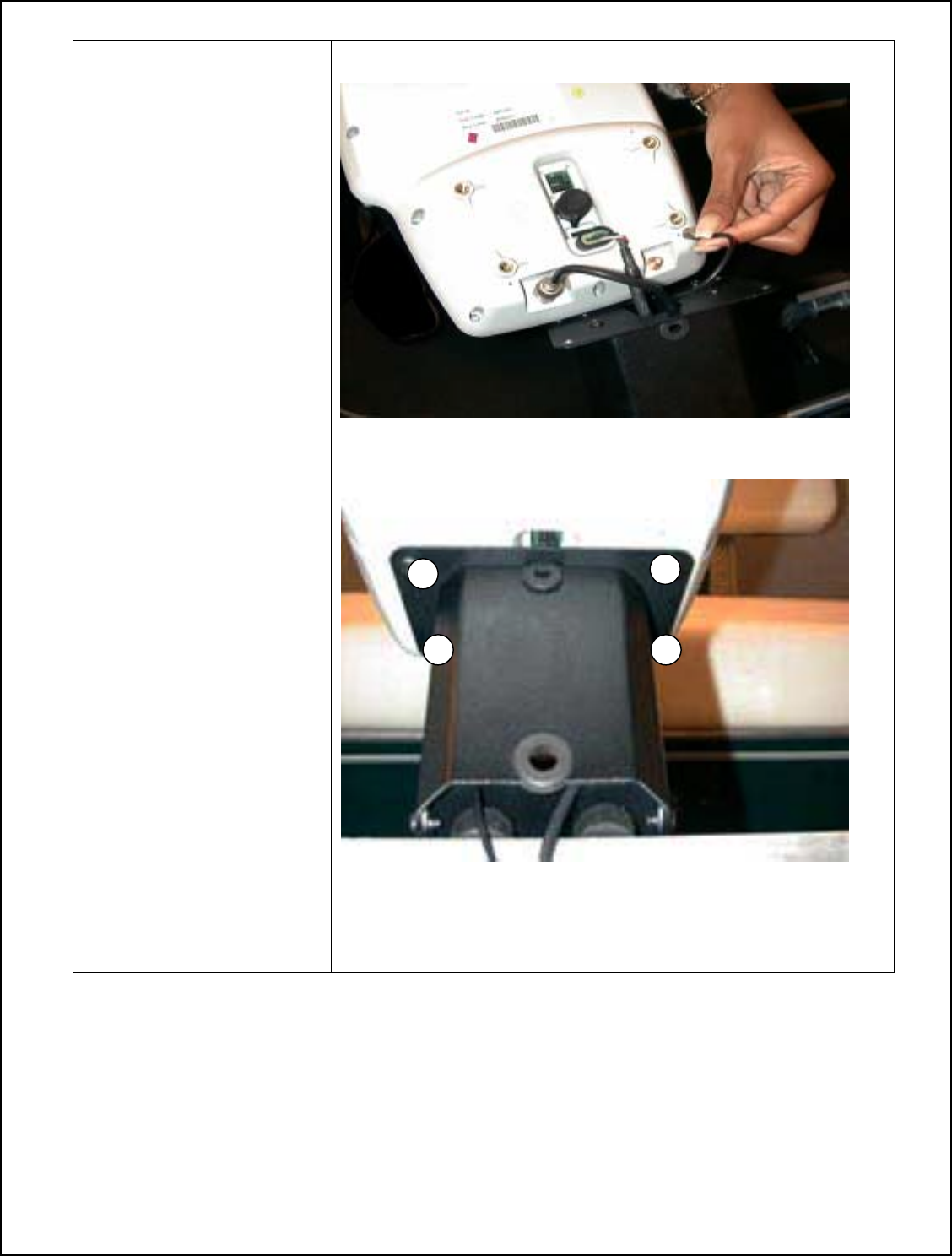
34
3. Attach GPS Connector
to Display Unit
4. Secure Display Unit to
Display Bracket using
hex head screws.
35
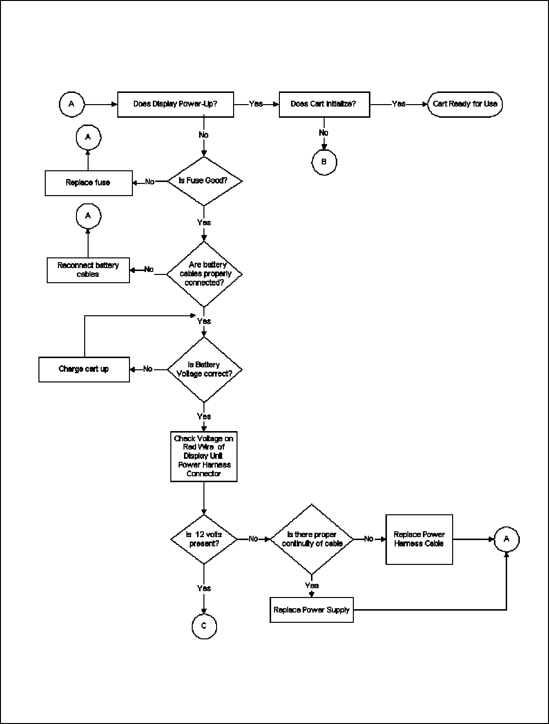
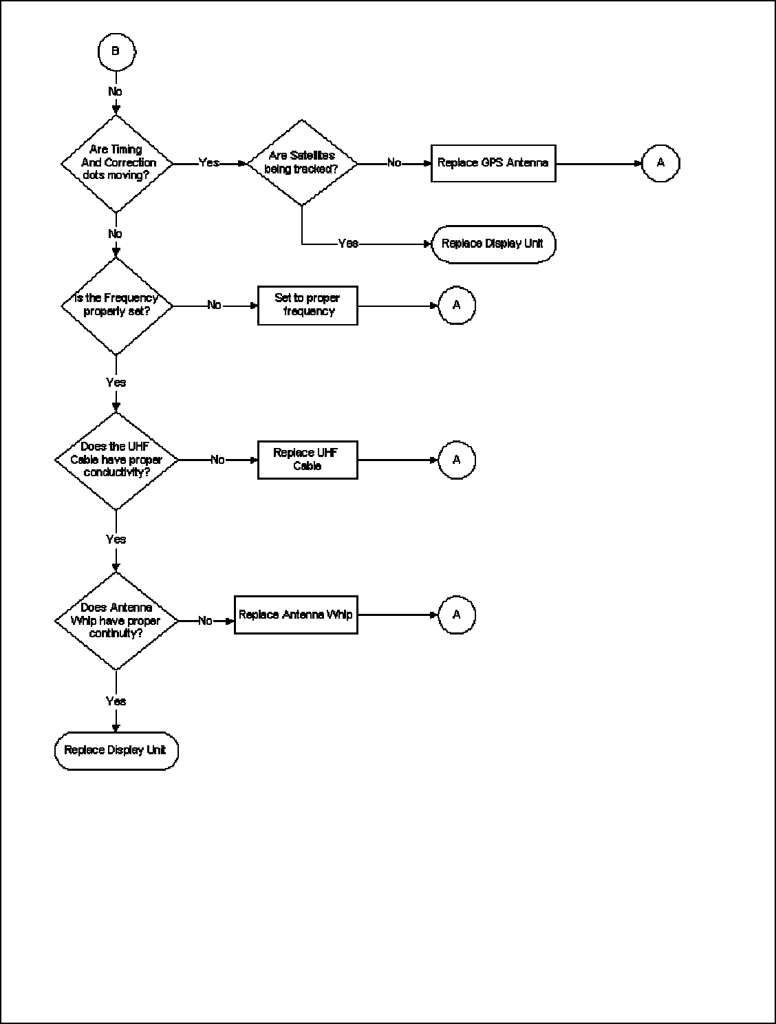
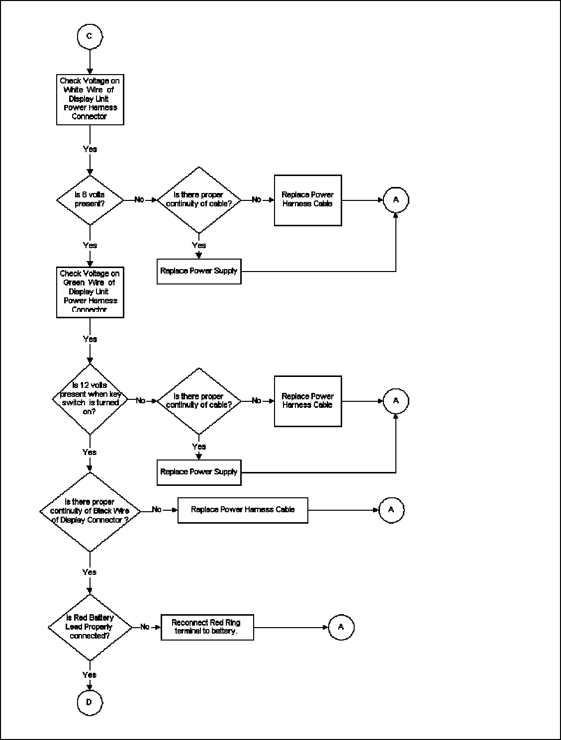
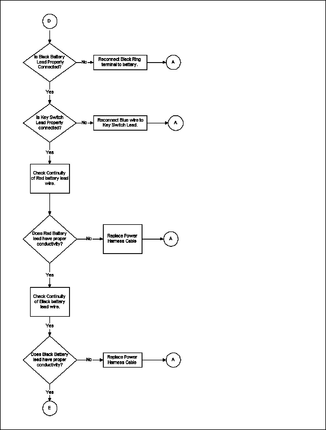
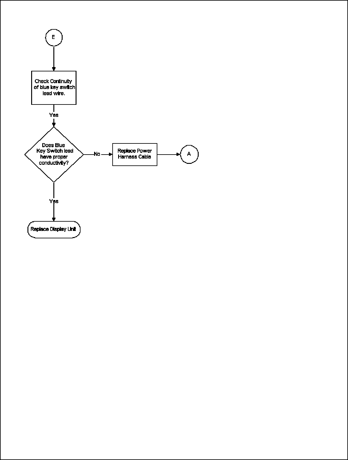
Trouble Shooting
36
37
38
39