Deere and ISG Electronic Systems JDGT-0001 Skylinks Head Unit and Skylinks Power Supply User Manual John Deere Golf Technologies
Phoenix International Corporation Skylinks Head Unit and Skylinks Power Supply John Deere Golf Technologies
Contents
- 1. Instruction Manual Part 1
- 2. Instruction Manual Part 2
- 3. Instruction Manual Part 3
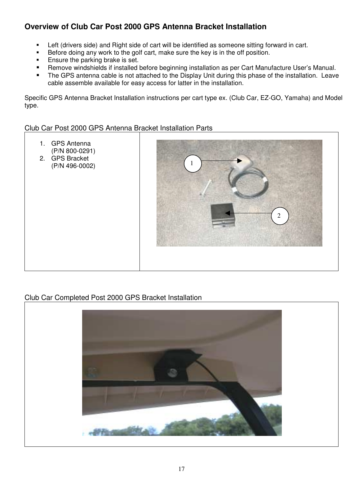
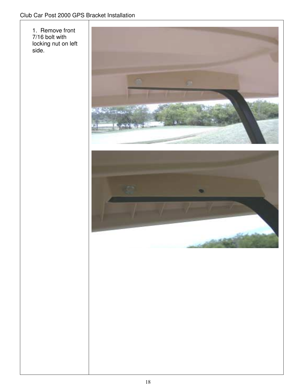
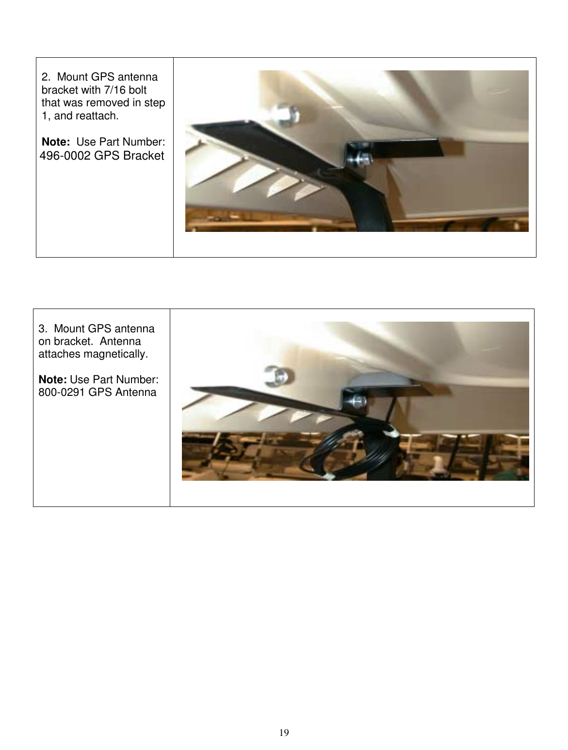
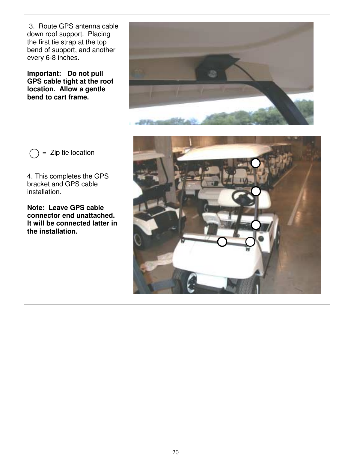
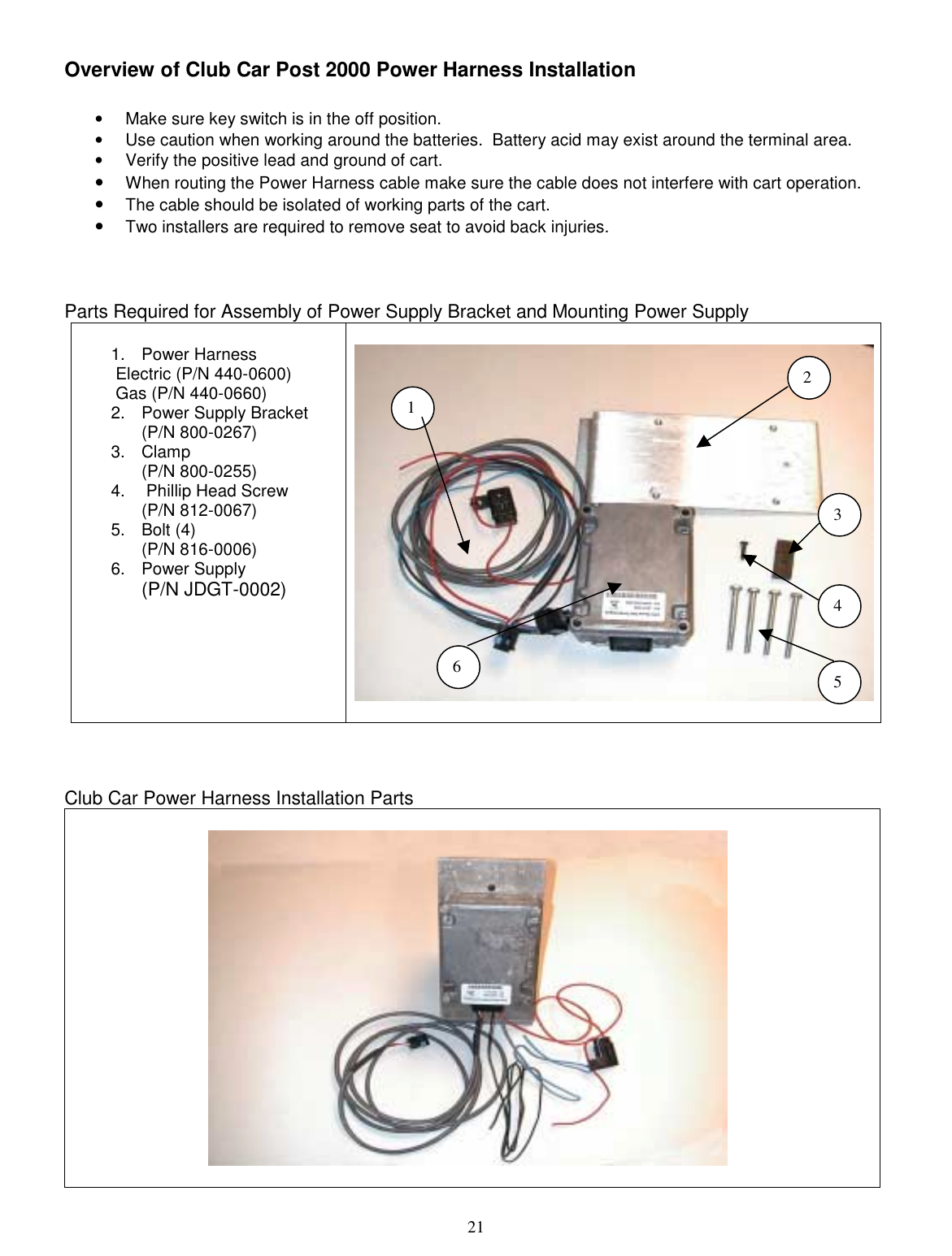
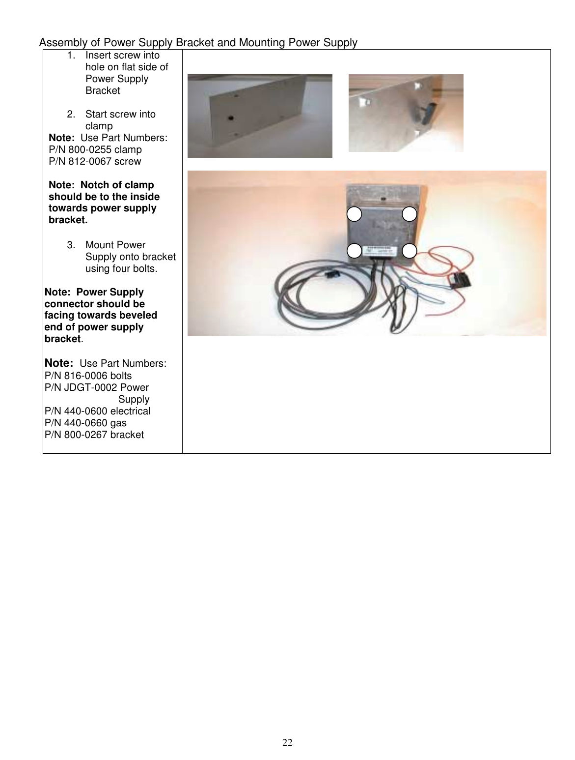
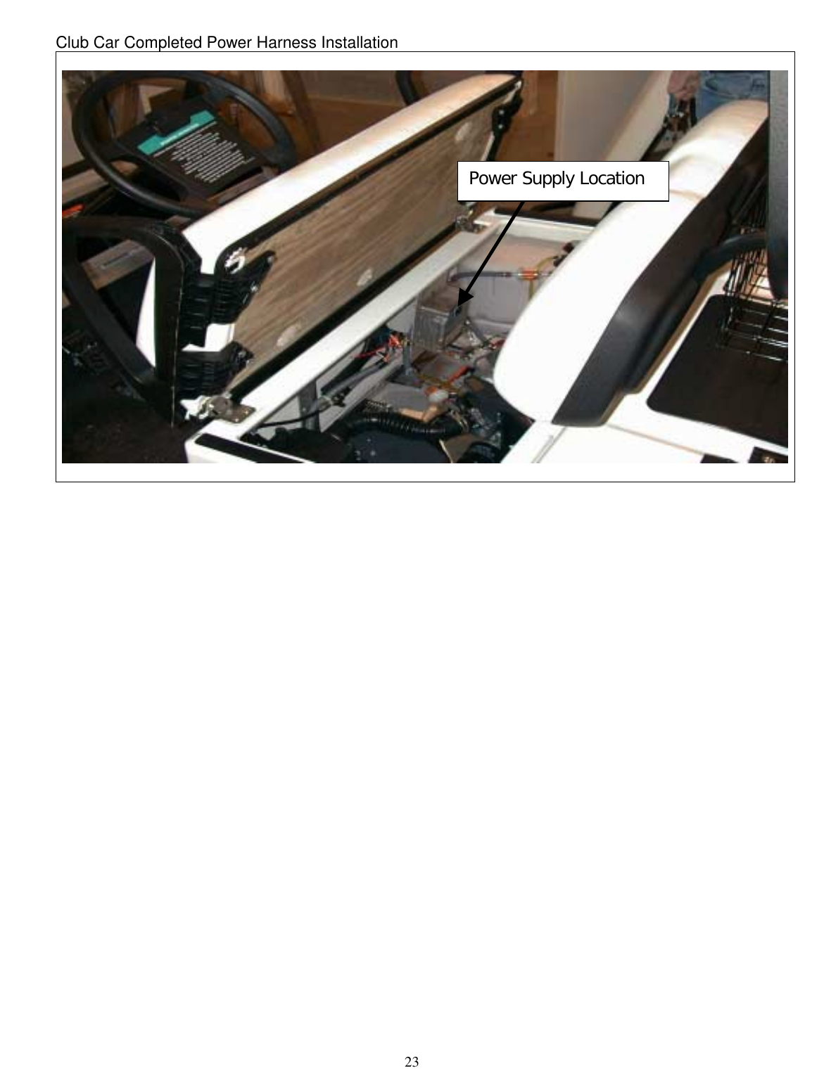
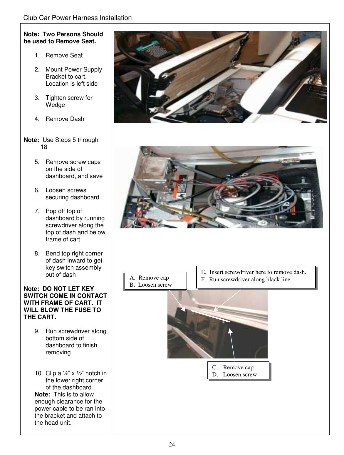
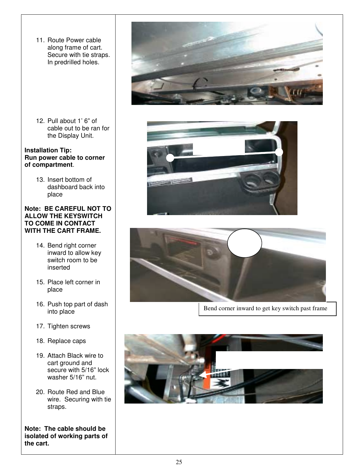
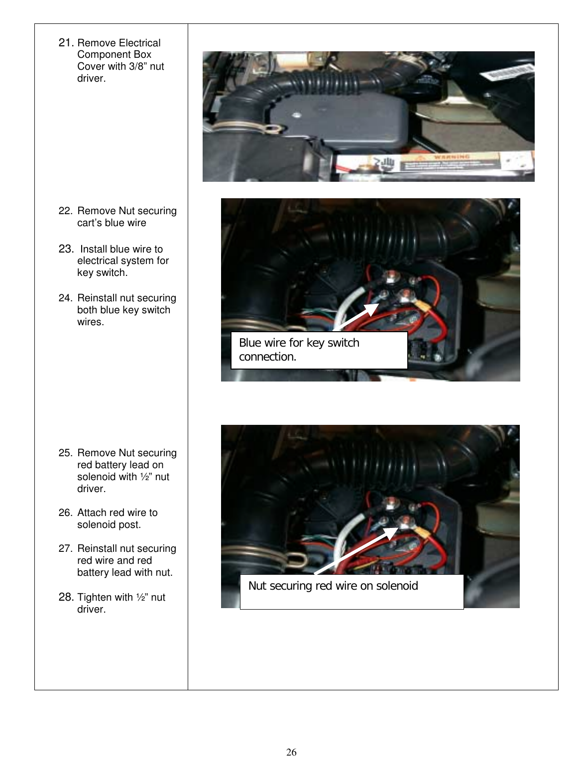
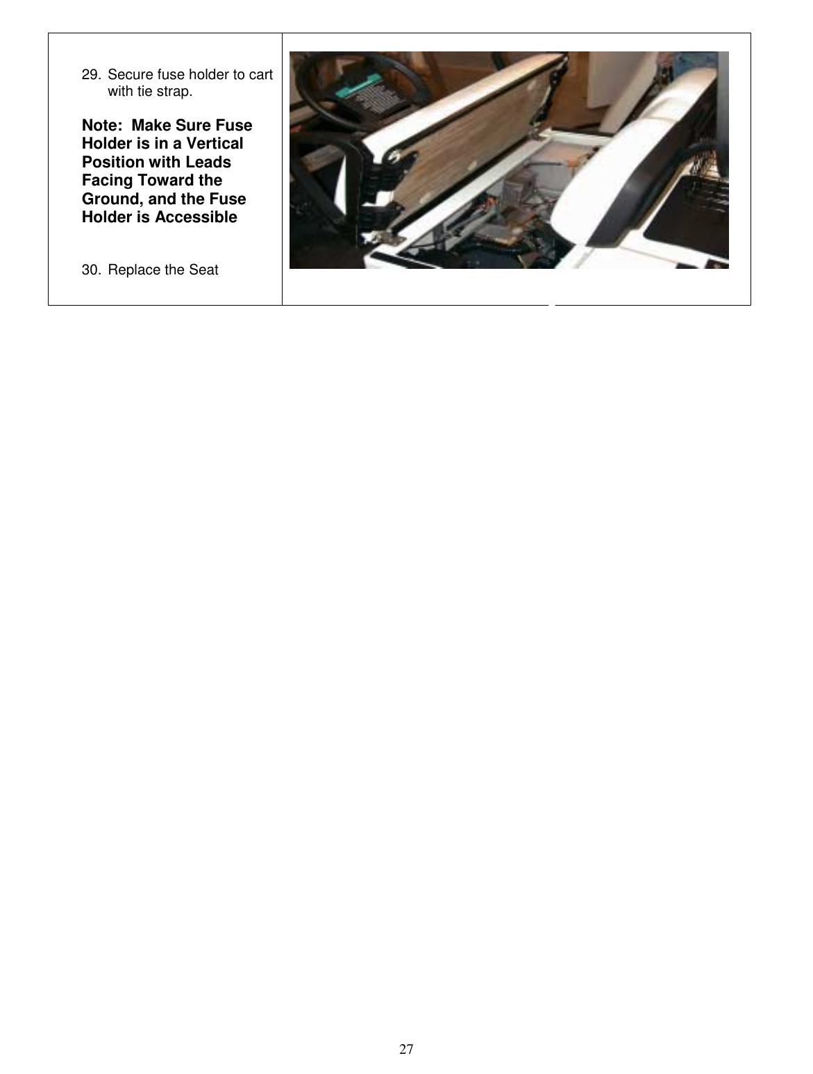
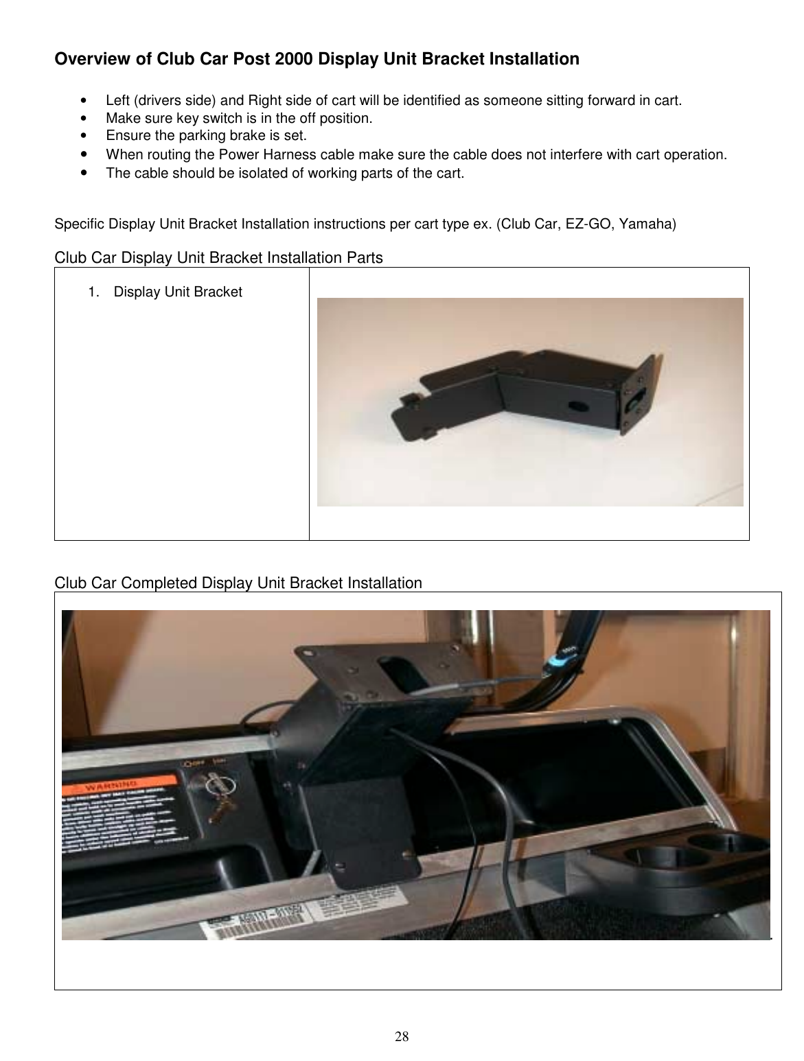
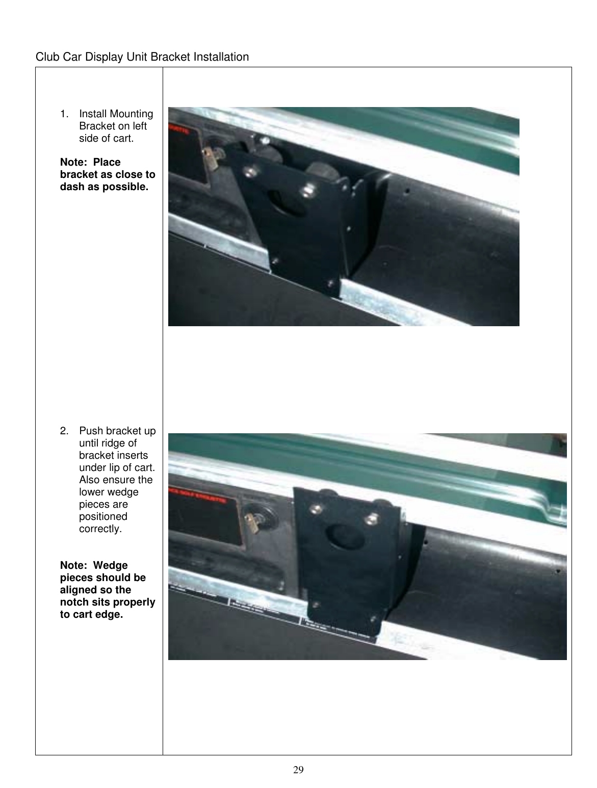
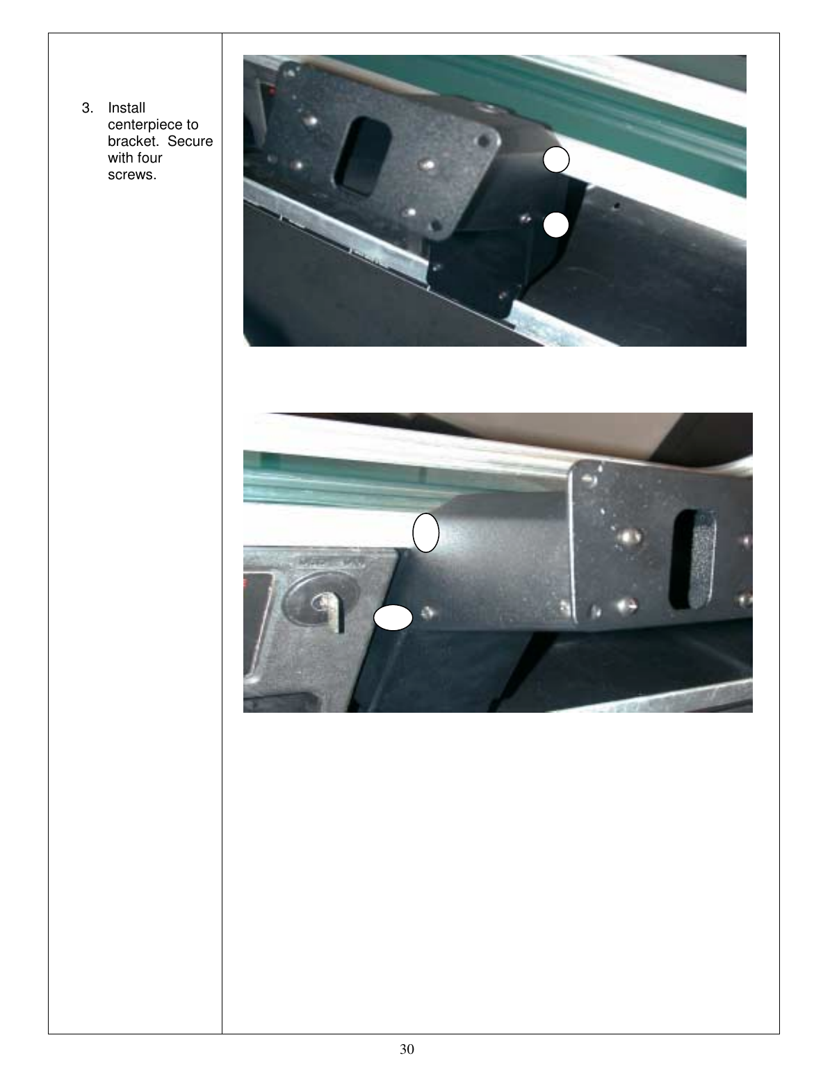
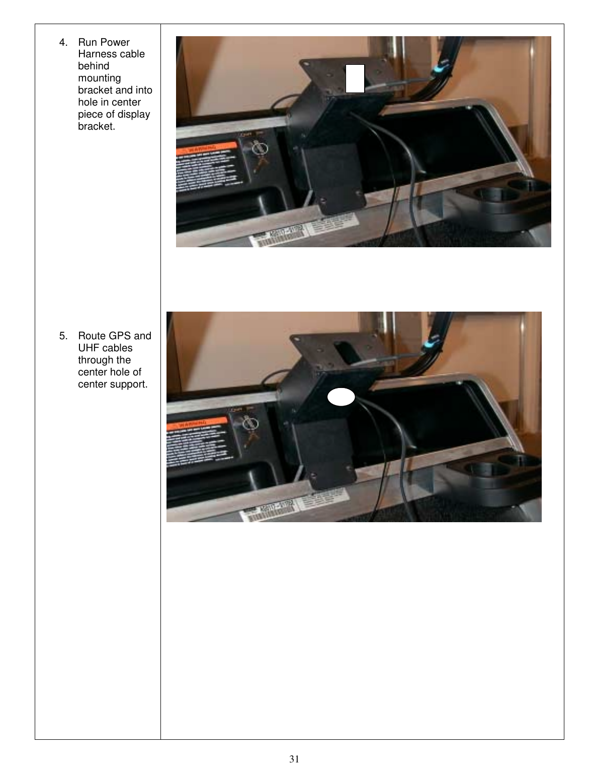
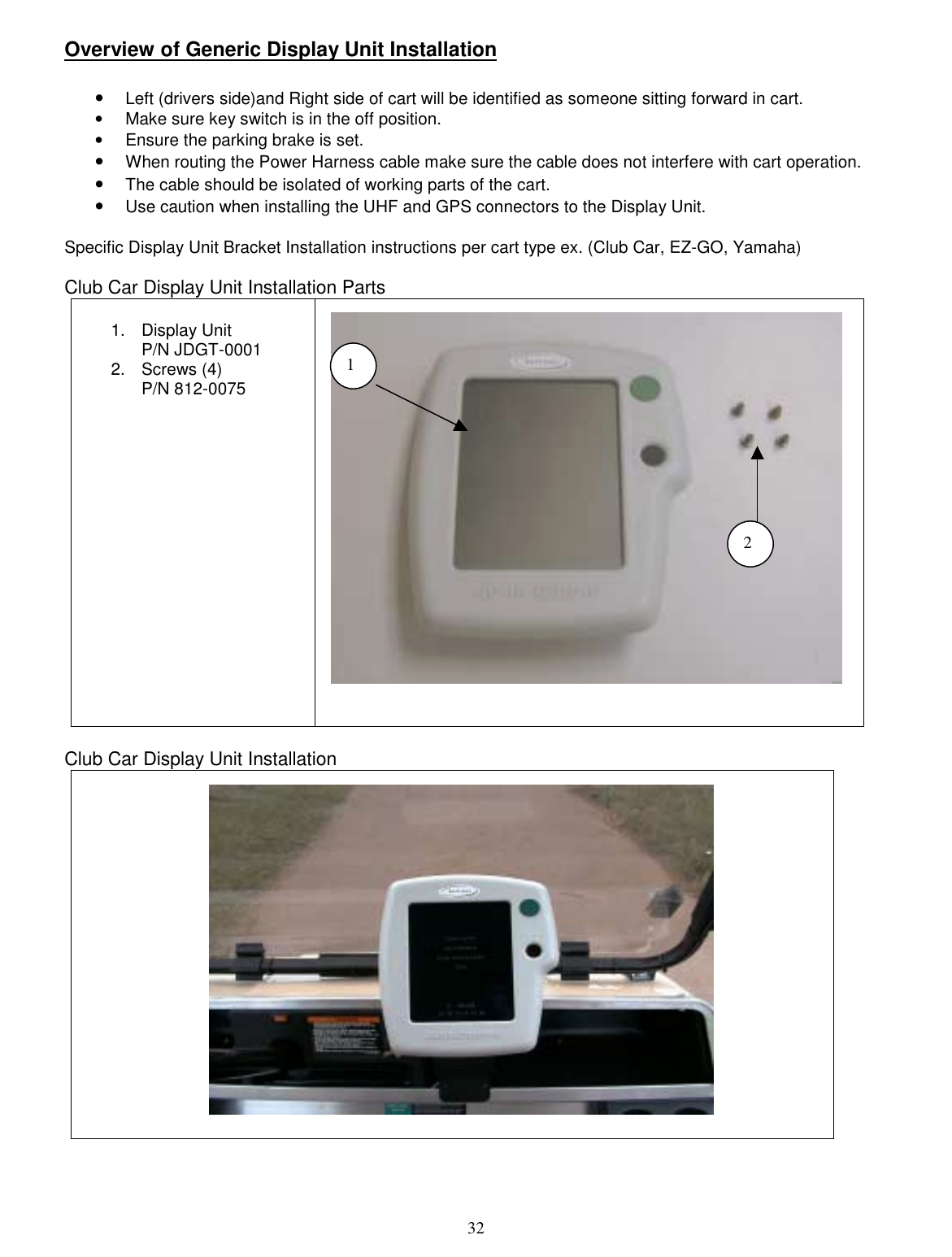
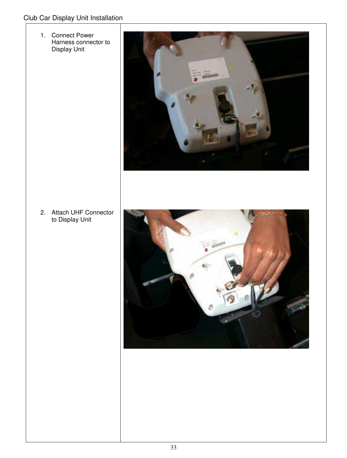
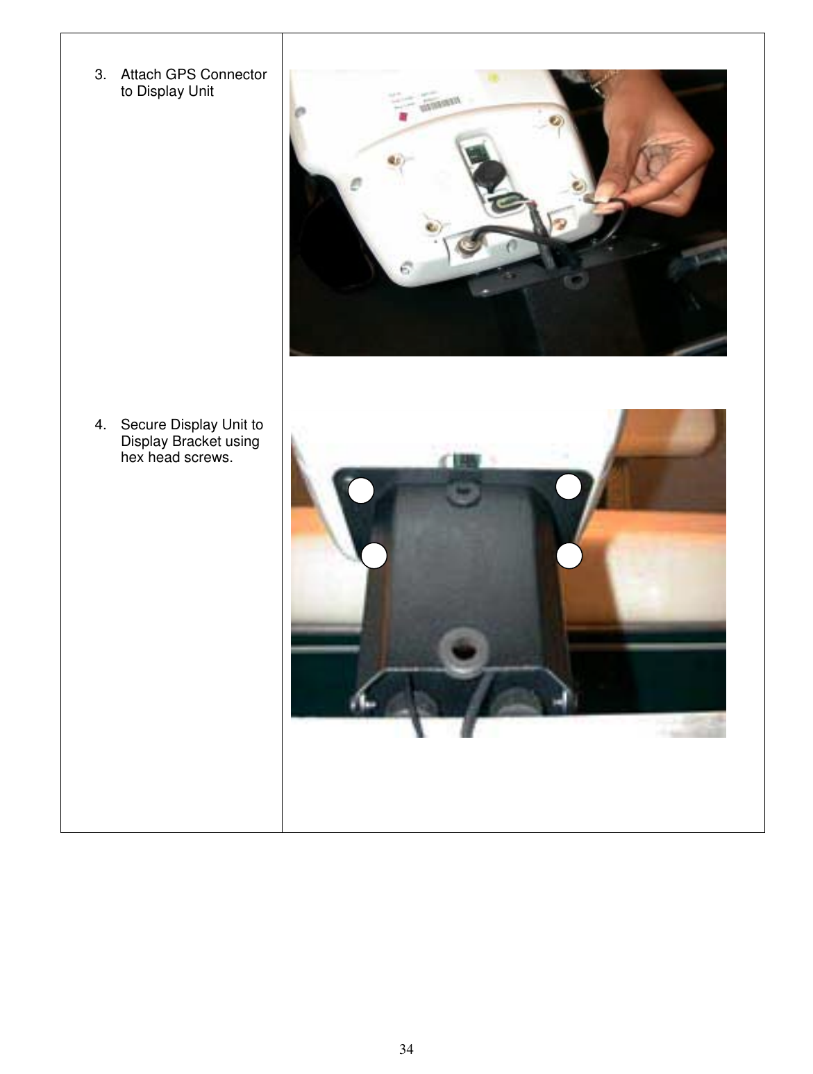
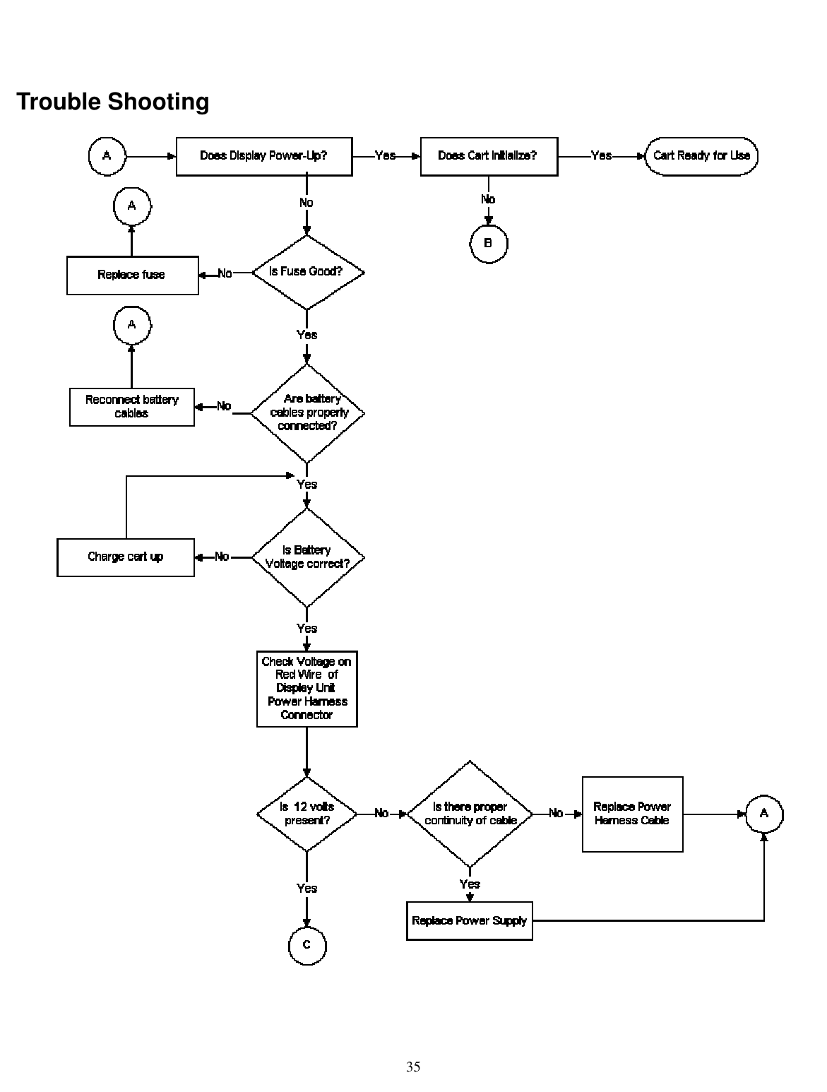
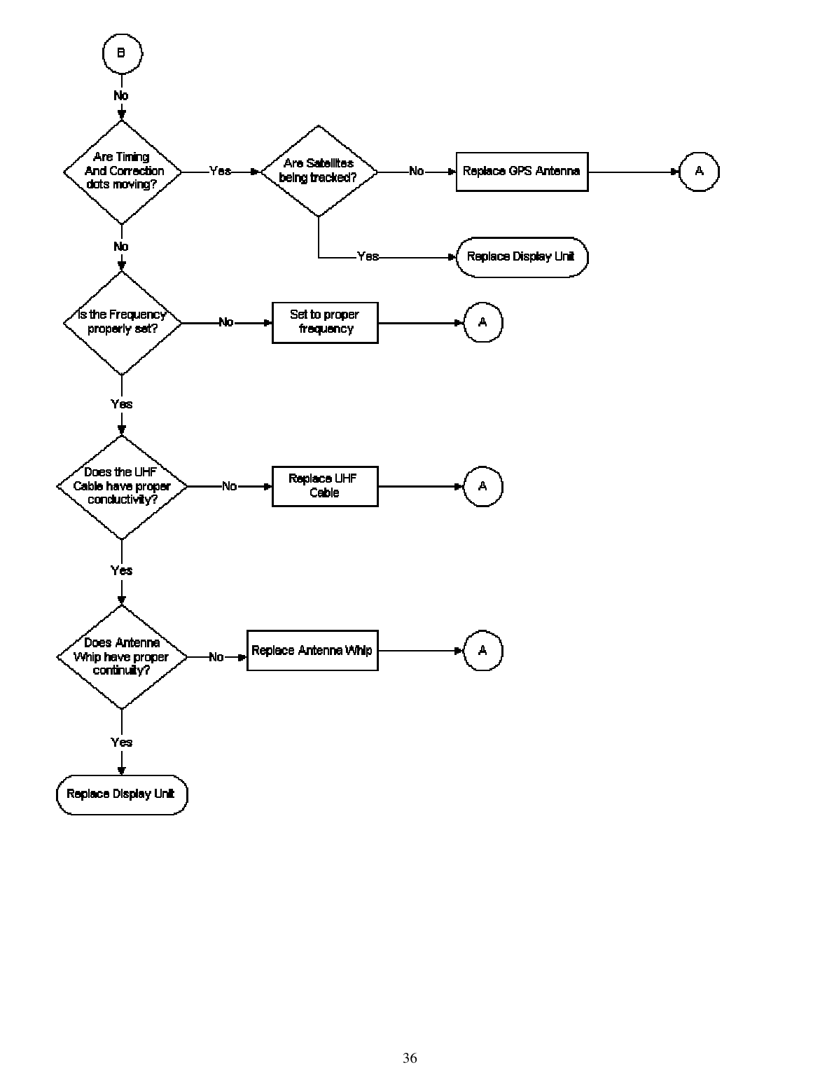
- 4. corrected installation manual
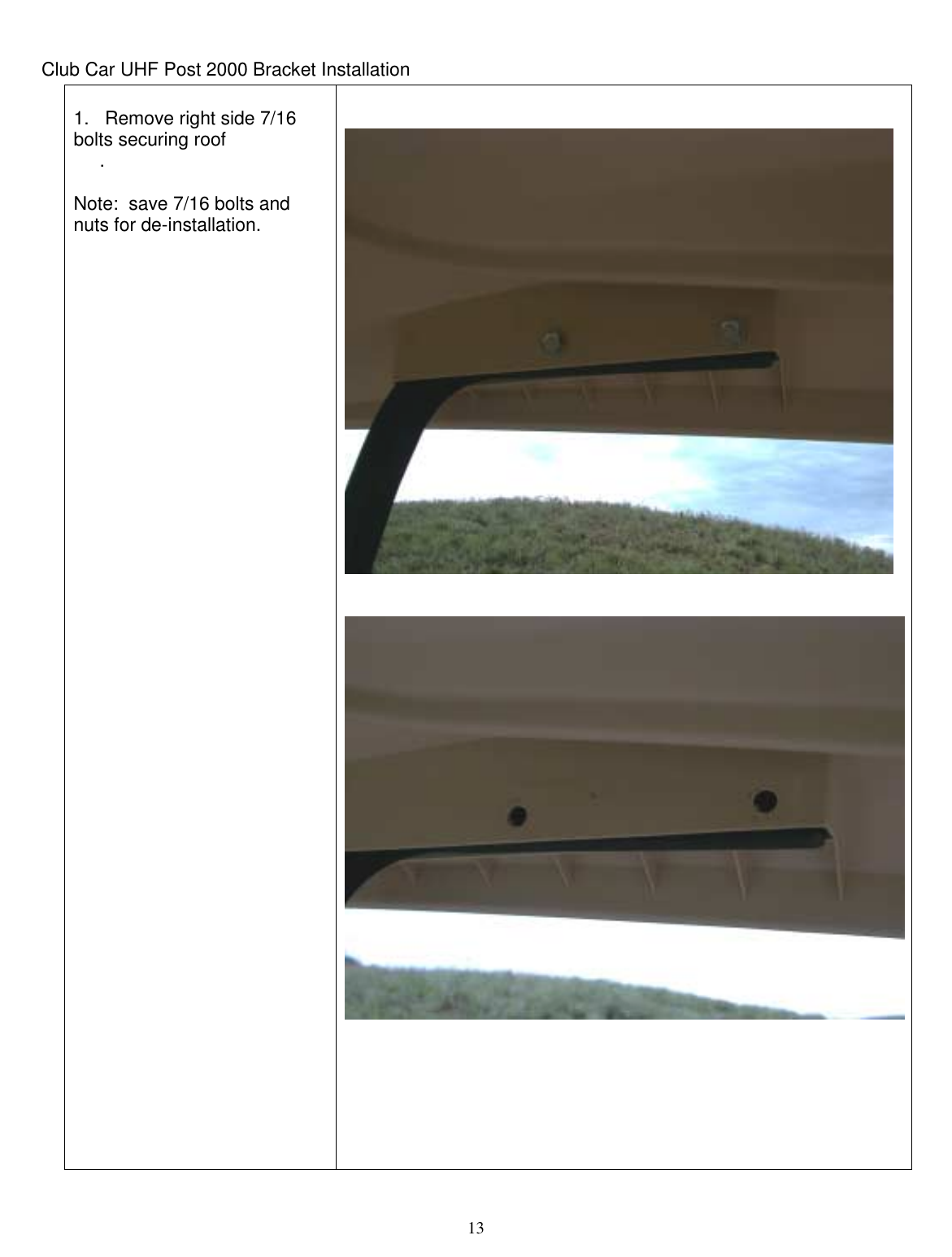
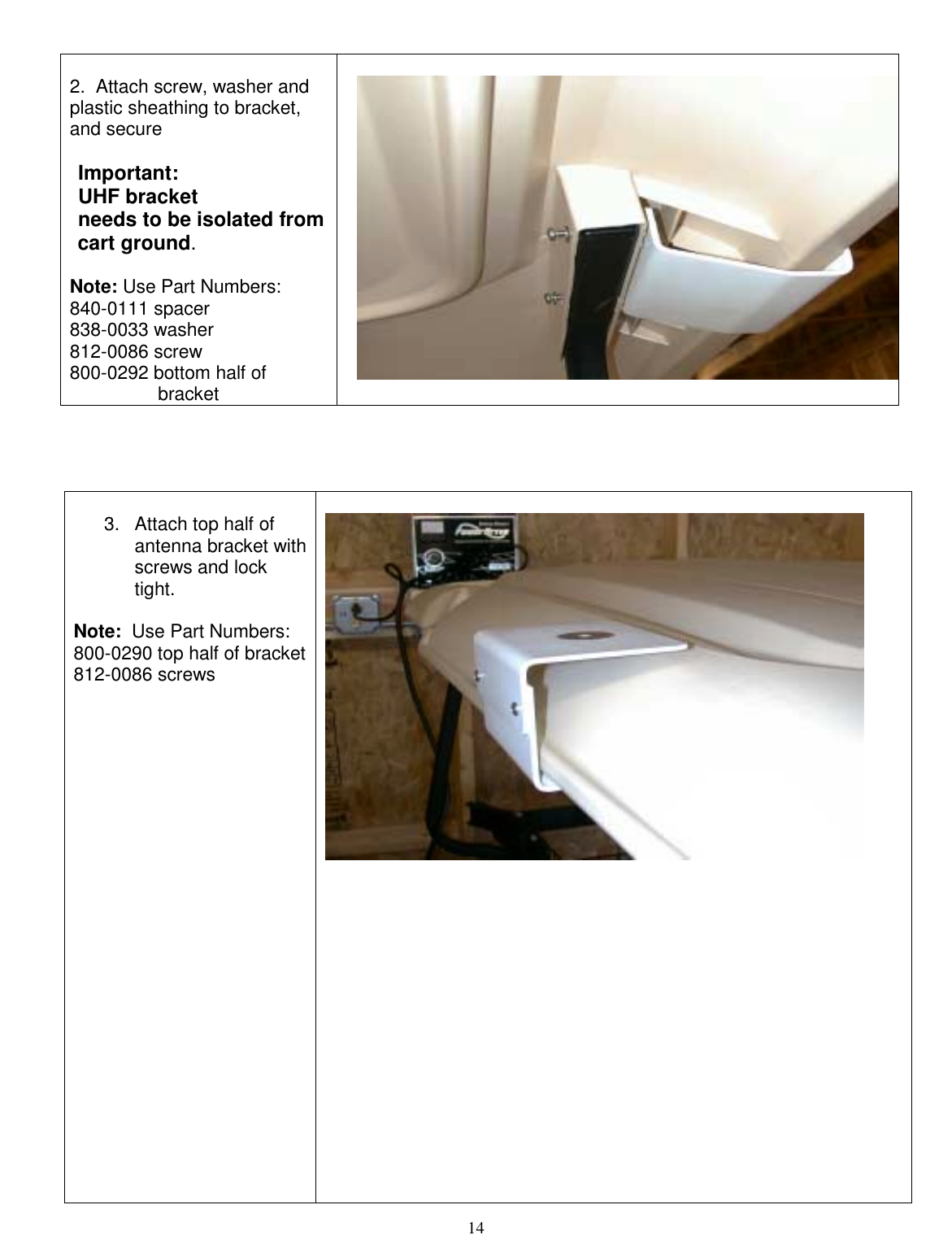
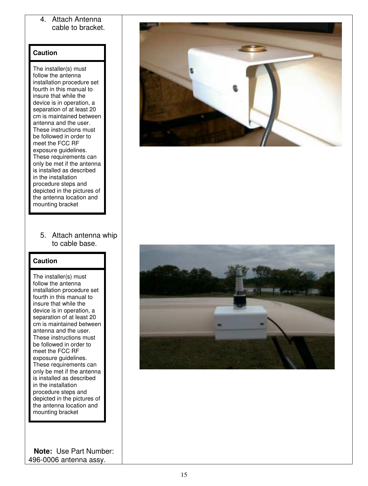
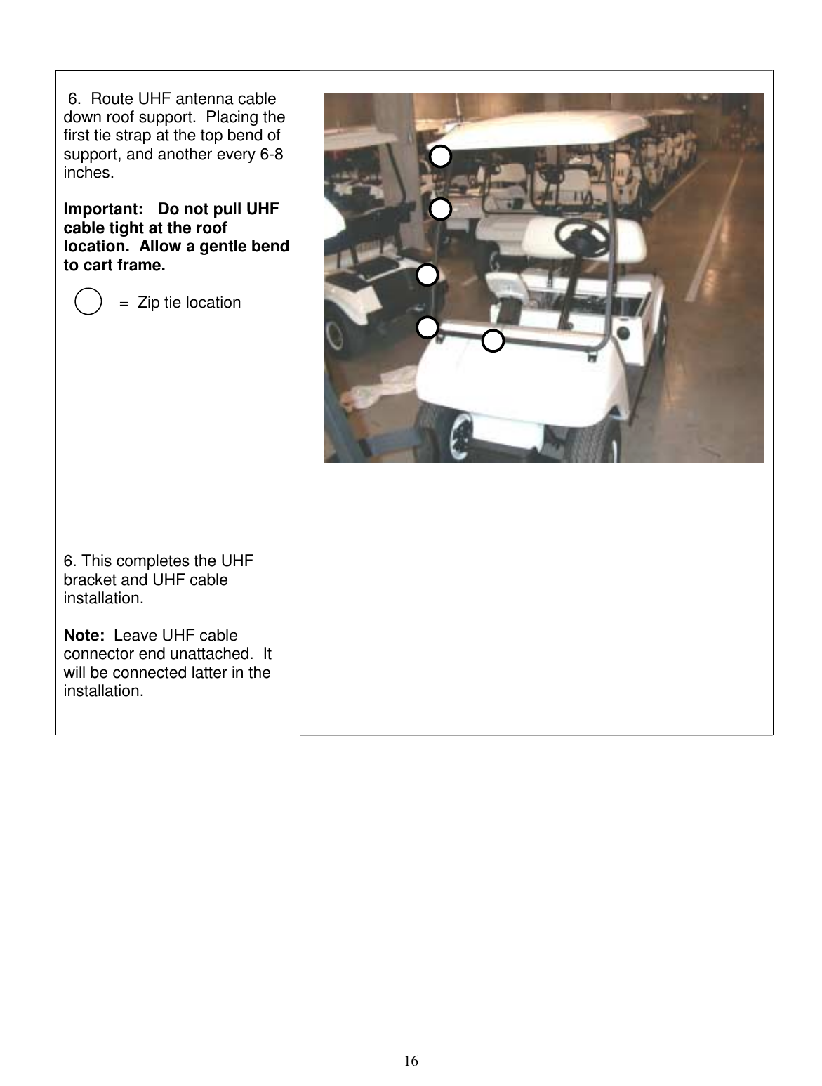
corrected installation manual