Deere and John Deere Intelligent Solutions Group PF80452 JDLINK Machine Messenger User Manual 102128UNIT
Deere & Company dba John Deere Intelligent Solutions Group JDLINK Machine Messenger 102128UNIT
manual

JDLINKMachine
Messenger
INSTALLATION INSTRUCTIONS
JDLINK Machine Messenger
PC20103 09JAN02 (ENGLISH)
8020, 9020
John Deere Ag Management Solutions
PC20103 (09JAN02)
COPYRIGHT 2001
DEERE & COMPANY
Moline, Illinois
All rights reserved
A John Deere ILLUSTRUCTION
Manual
PC20103-19-09JAN02
P R O O F P R O O F
Installation Instructions
DX,ALERT –19–29SEP98–1/1
Recognize Safety Information
T81389 –UN–07DEC88
This is a safety-alert symbol. When you see this symbol
on your machine or in this manual, be alert to the
potential for personal injury.
Follow recommended precautions and safe operating
practices.
OUO6091,0001435 –19–20AUG01–1/1
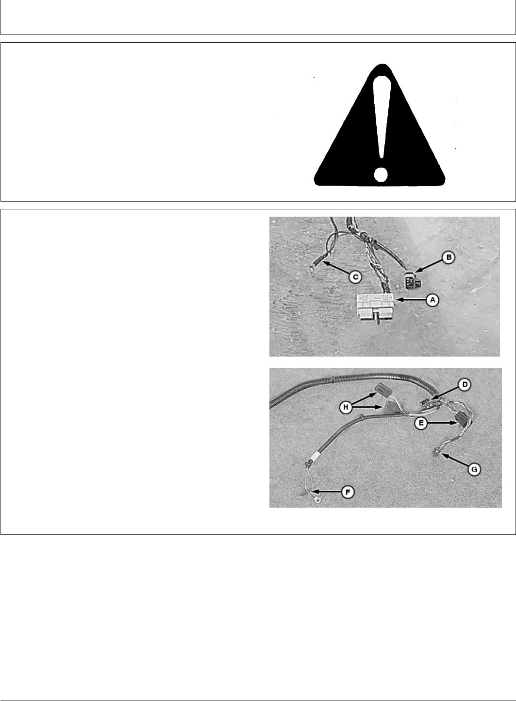
JDLINK Wiring Harness Reference
PC6783 –UN–19DEC01
PC6782 –UN–19DEC01
A—Socket Connector To Controller
B—CAN Bus Terminator Connector
C—Ground wire
D—CCD Bus Connector
E—CAN Bus Terminator Connector
F—Unswitched And Switch Power Wires
G—SCV Panel Connector
H—10 Amp Fuses
(09JAN02)
1
Installation Instructions
010902
PN=3
P R O O F P R O O F

Installation Instructions
OUO6091,0001433 –19–14AUG01–1/27
Install JDLINKMachine Messenger
IMPORTANT: Avoid damage to electrical system of
tractor when installing JDLINK wiring
harness. Disconnect battery ground.
NOTE: After installing JDLINK Machine Messenger and
before reassembling cab roof, login to JDLINK
website at www.jdlink.com, go to Dealer
Menu/Setup New Device wizard and follow online
procedures. These procedures will allow JDLINK
communication controller’s serial number to be
verified and tractor’s serial number to be entered
for proper system operation.
Reference of JDLINK Machine Messenger’s
Technical Manual is required for this instruction.
1. Shut off engine, set parking brake and remove key.
JDLINK is a trademark of Deere & Company
Continued on next page
(09JAN02)
2
Installation Instructions
010902
PN=4
P R O O F P R O O F
Installation Instructions
OUO6091,0001433 –19–14AUG01–2/27
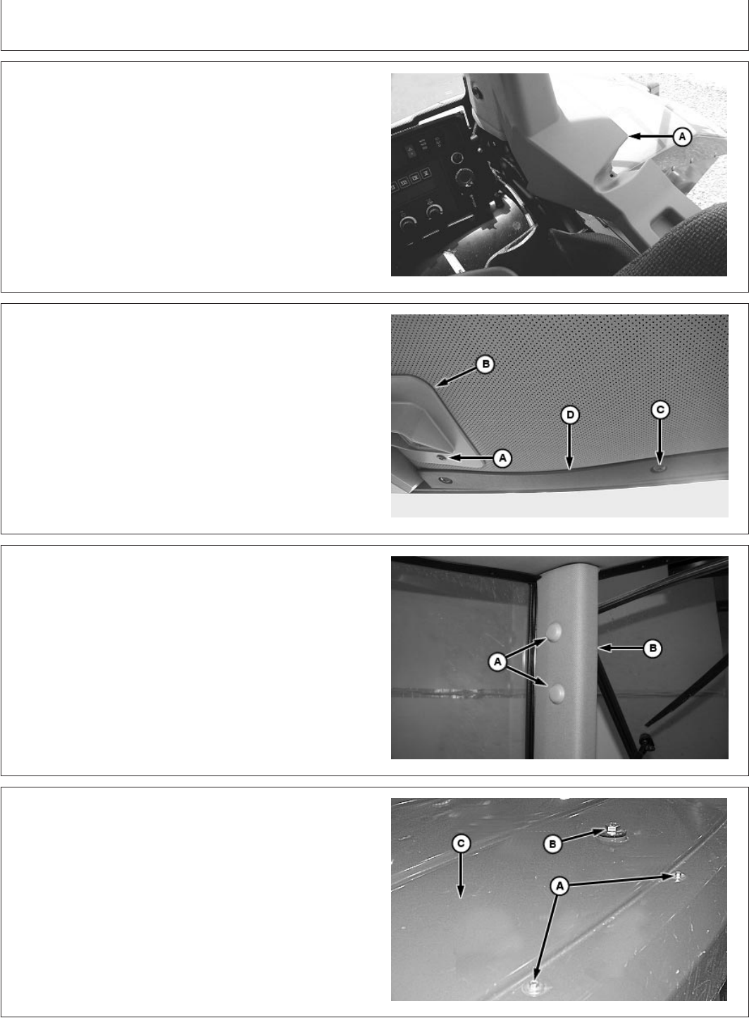
PC6928 –UN–28NOV01PC6929 –UN–28NOV01PC6931 –UN–29NOV01PC6930 –UN–28NOV01
A—TORX Screws
B—Plastic Rivets
C—Cap Screw
D—Screws
E—Console Cover
NOTE: If tractor is equipped with JDLINK wiring harness
go to step 11.
2. Remove TORX
screws (A).
3. Remove plastic rivets (B).
4. Remove cap screw (C).
NOTE: To access console screws (D), remove fuse panel
cover.
5. Remove screws (D) and console cover (E).
TORX is a trademark of Camcar/Textron
(09JAN02)
3
Installation Instructions
010902
PN=5
P R O O F P R O O F
Continued on next page
Installation Instructions
OUO6091,0001433 –19–14AUG01–3/27
PC6764 –UN–14AUG01
A—Shroud Screws
B—Post Shroud
6. Remove right rear shroud screws (A) and shroud (B).
OUO6091,0001433 –19–14AUG01–4/27
PC6934 –UN–28NOV01
A—Screw
B—Light
C—Trim Screws
D—Trim
NOTE: Remove headliner enough to route wiring harness
down right-rear corner post.
7. Remove screw (A), light (B), trim screws (C) and
headliner trim (D).
OUO6091,0001433 –19–14AUG01–5/27
PC6933 –UN–28NOV01
A—Rear Window Molding
8. Remove right rear window molding (A).
OUO6091,0001433 –19–14AUG01–6/27
PC6766 –UN–28NOV01
A—Screw
B—Panel Spacer
C—SCV Panel
9. Remove screw (A), panel spacer (B) and SCV setup
panel (C).
(09JAN02)
4
Installation Instructions
010902
PN=6
P R O O F P R O O F
Continued on next page
Installation Instructions
OUO6091,0001433 –19–14AUG01–7/27
PC6767 –UN–19DEC01
A—CAN Bus Terminator
NOTE: CAN bus terminator will be reinstalled on roof of
cab in a following step.
10. Disconnect and remove CAN bus terminator (A).
OUO6091,0001433 –19–14AUG01–8/27
PC6762 –UN–14AUG01
A—Cap Screws
B—Mirror
11. Remove flange cap screws (A) and mirror (B).
12. Disconnect and remove STARFIREreceiver, if
equipped.
NOTE: Refer to machine Technical Manual for removal of
rear cab lights and radio antenna.
13. Remove rear cab lights and disconnect radio antenna.
STARFIRE is a trademark of Deere & Company
OUO6091,0001433 –19–14AUG01–9/27
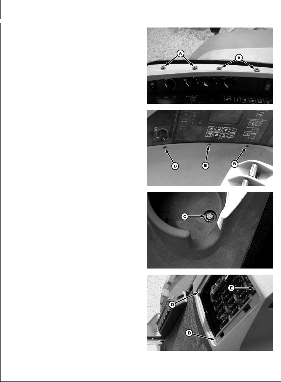
PC6763 –UN–14AUG01
A—Cap Screws (16 used)
B—Cap Screws (2 used)
C—Cab Roof
NOTE: Cab roof is awkward to handle, use suitable lifting
device or two technicians.
14. Remove cap screws (A and B), washers and cab
roof (C).
Continued on next page
(09JAN02)
5
Installation Instructions
010902
PN=7
P R O O F P R O O F
Installation Instructions
OUO6091,0001433 –19–14AUG01–10/27
PC6781 –UN–20AUG01PC6771 –UN–20AUG01
A—Coax
B—Coax
C—Antenna Assembly
D—Cap Screws
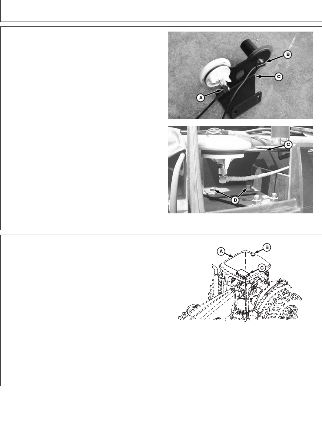
15. Connect coax cables (A and B) to antenna assembly
(C).
IMPORTANT: Improperly installed antenna and
receiver may interfere with the
operation of machine’s electronic
system and possibly subject operator to
higher than recommended radio
frequency emission levels.
16. Attach antenna assembly to right rear-window hinge
using existing cap screws (D).
OUO6091,0001433 –19–14AUG01–11/27
PC6938 –UN–29NOV01
Reference Of 8020
A—Coax Cable
B—Antenna Assembly
C—Controller
NOTE: For all machines, route coax cables on right side
of cab.
17. Route coax cables (A) on right side of tractor cab
from antenna assembly (B) to controller (C).
Continued on next page
(09JAN02)
6
Installation Instructions
010902
PN=8
P R O O F P R O O F
Installation Instructions
OUO6091,0001433 –19–14AUG01–12/27
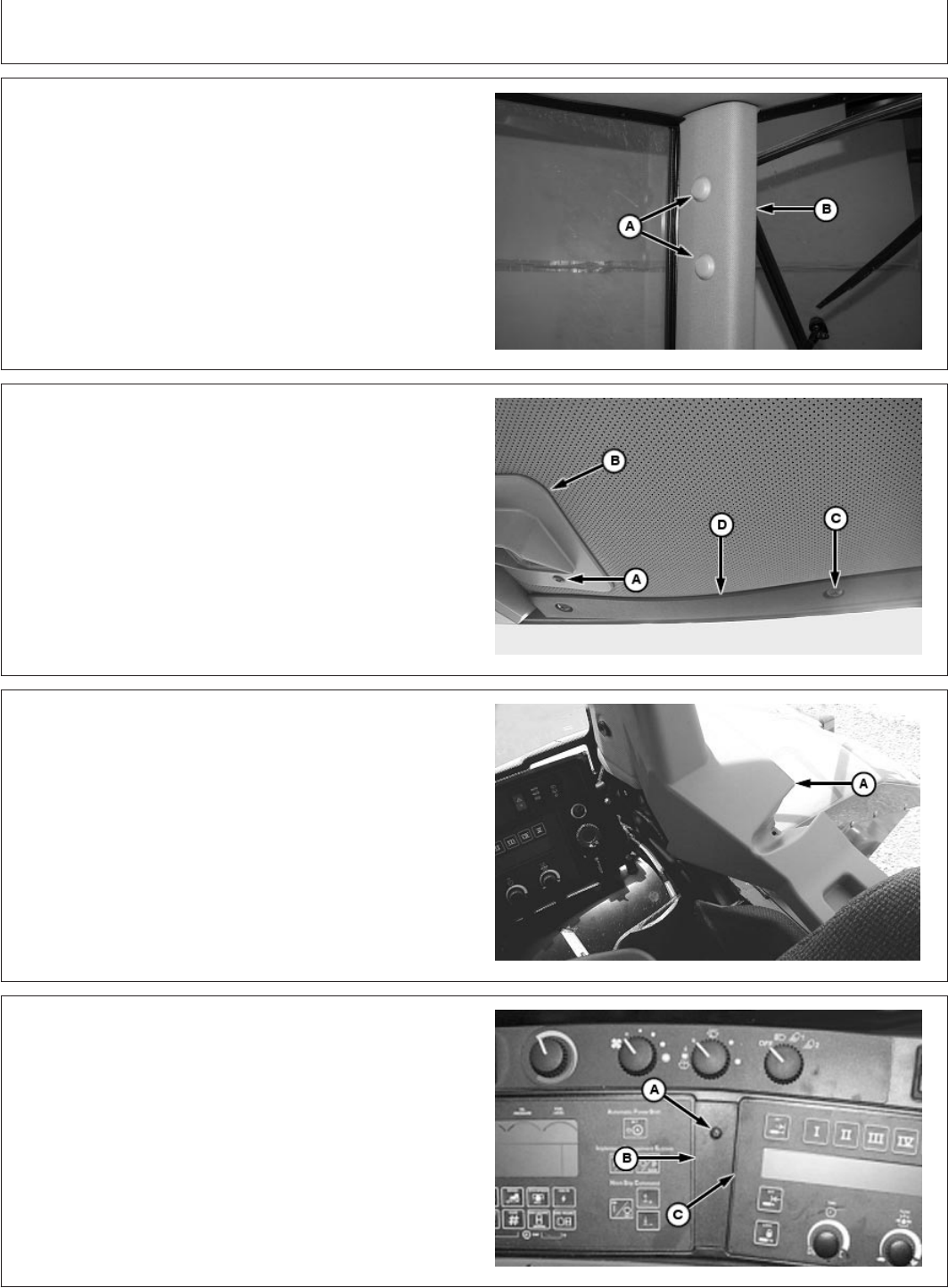
PC6768 –UN–14AUG01
PC6769 –UN–16AUG01
PC6760 –UN–10AUG01
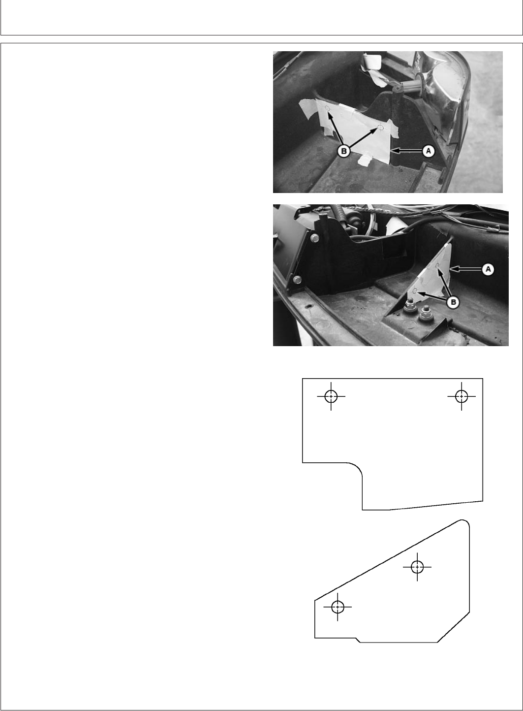
Template (Reference Only)
A—Template
B—Hole Guides
NOTE: Use pullout templates (included with this
instruction) to locate and drill holes at left front
section of cab. Templates below are for reference
only. If tractor is equipped with JDLINK wiring
harness, skip to step 21.
18. Install templates (A) and tape corners of templates to
brackets. Locate and mark four holes (B) for drilling.
19. Remove templates.
20. Drill four 8 mm (5/16 in) holes (B).
(09JAN02)
7
Installation Instructions
010902
PN=9
P R O O F P R O O F
Continued on next page
Installation Instructions
OUO6091,0001433 –19–14AUG01–13/27
PC6773 –UN–28NOV01
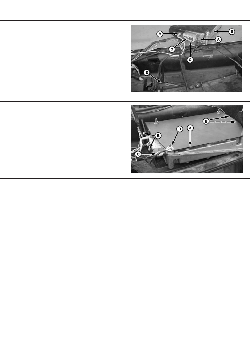
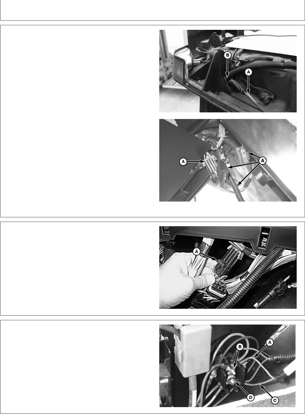
21. Attach coax cables (A) to controller (B).
22. Connect JDLINK wiring harness connector (C) to
controller and tighten cap screw (D).
NOTE: Record controller’s 13 digit serial number for a
following step.
23. Install terminator (E) and retain with tie straps.
OUO6091,0001433 –19–14AUG01–14/27
PC6780 –UN–28NOV01
A—Controller
B—Cap Screws (4 used)
C—Ground Wire
D—Nut
24. Attach controller (A), using four 6 mm cap screws (B).
25. Attach ground wire from JDLINK wiring harness (C) to
controller using existing nut (D).
Continued on next page
(09JAN02)
8
Installation Instructions
010902
PN=10
P R O O F P R O O F
Installation Instructions
OUO6091,0001433 –19–14AUG01–15/27
B
A
C
D
PC6761 –UN–15AUG01
Ground Wire Route For 8020 Wheel And 9020 Track
PC6966 –UN–18DEC01
Ground Wire Route for 9020 Wheel
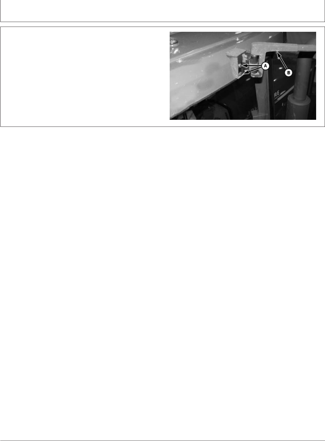
PC6774 –UN–14AUG01
Chassis Ground for 8020
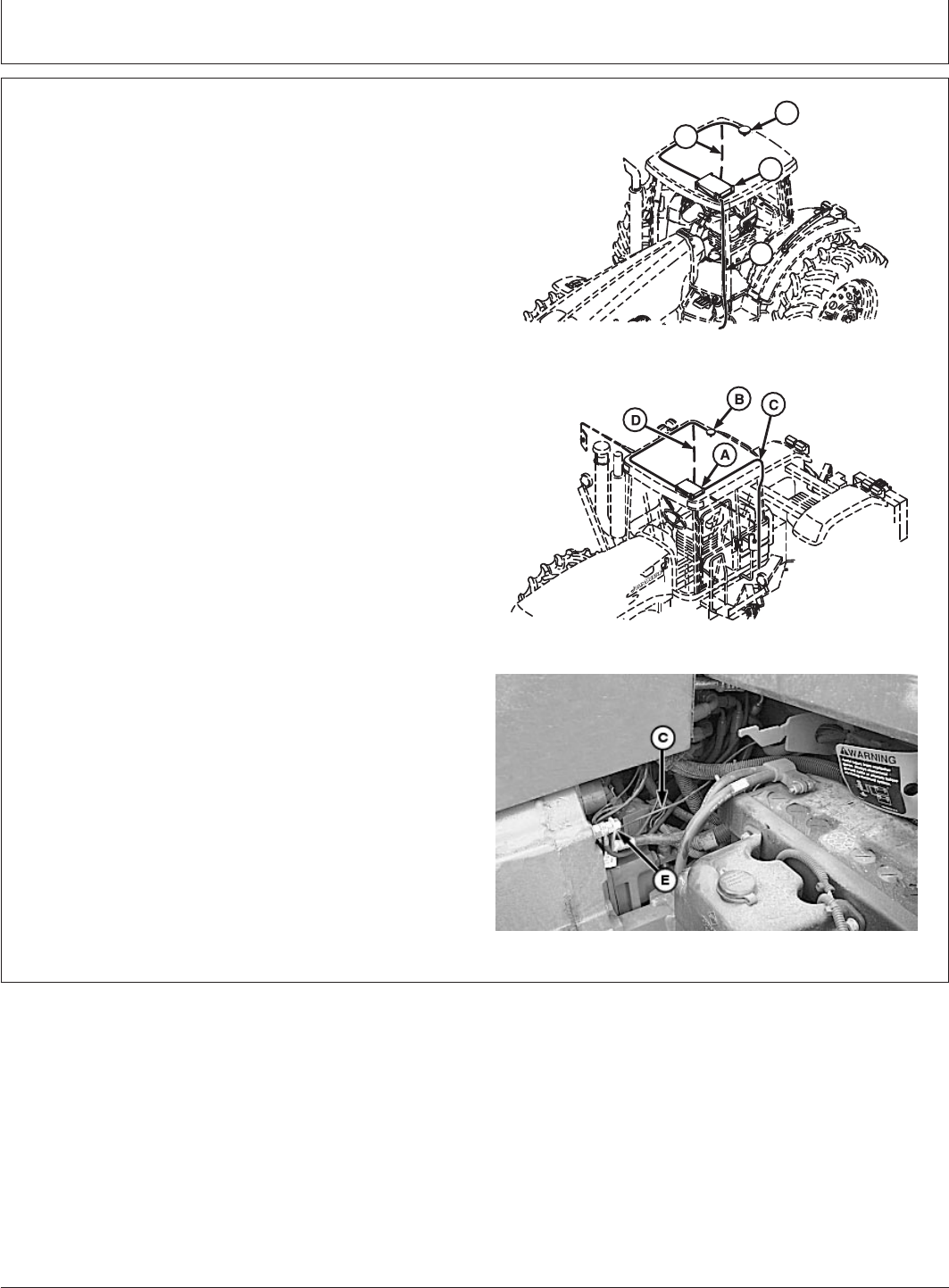
A—JDLINK Controller
B—JDLINK Antenna Assembly
C—Ground Wire
D—JDLINK Wiring Harness
E—Chassis Post
NOTE: Record machine’s 13 digit serial number for a
following step.
If equipped with JDLINK wiring harness skip to
step 32.
Place controller ground wire next to chassis
behind second nut.
26. Route ground wire (C) along side of windshield
washer hose and connect to chassis ground (E).
Continued on next page
(09JAN02)
9
Installation Instructions
010902
PN=11
P R O O F P R O O F
Installation Instructions
OUO6091,0001433 –19–14AUG01–16/27
PC6775 –UN–14AUG01PC6939 –UN–28NOV01
A—JDLINK Wiring Harness
B—Cab Slot
IMPORTANT: Avoid damage to antenna coax cables
and JDLINK wiring harness when
reinstalling cab roof. Tie strap wiring
harness and coax cables in areas on
top of cab to prevent damage of wires
and cables (tie strap cables and wiring
harness together from right rear cab
slot to controller).
27. Route JDLINK wiring harness (A) to SCV panel
through slot (B) at right rear cab post.
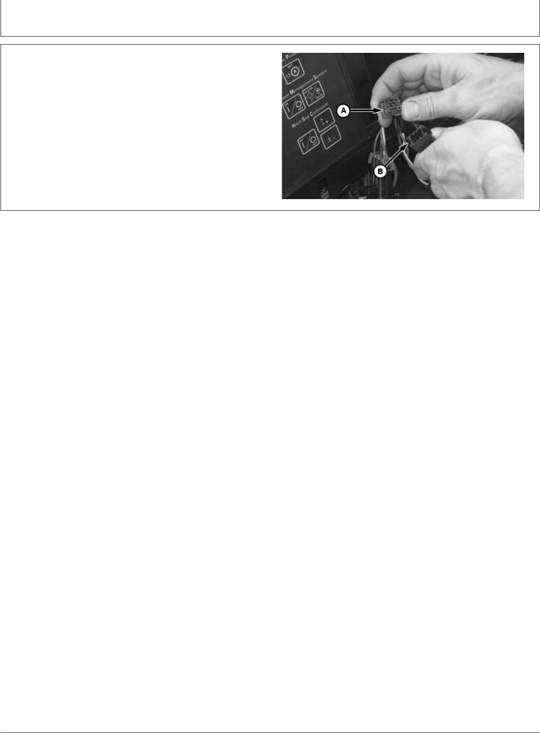
OUO6091,0001433 –19–14AUG01–17/27
PC6971 –UN–20DEC01
A—JDLINK Connector And CAN Bus Terminator
Connector
28. Connect JDLINK connector to CAN bus terminator
connector (A).
OUO6091,0001433 –19–14AUG01–18/27
PC6777 –UN–14AUG01
A—Unswitch Power Wire, 262
B—Post
C—Switch Power Wire, 192
D—Power Post
29. Connect JDLINK unswitch power wire (A) to post (B)
and power switch wire (C) to post (D) with hardware
provided.
(09JAN02)
10
Installation Instructions
010902
PN=12
P R O O F P R O O F
Continued on next page
Installation Instructions
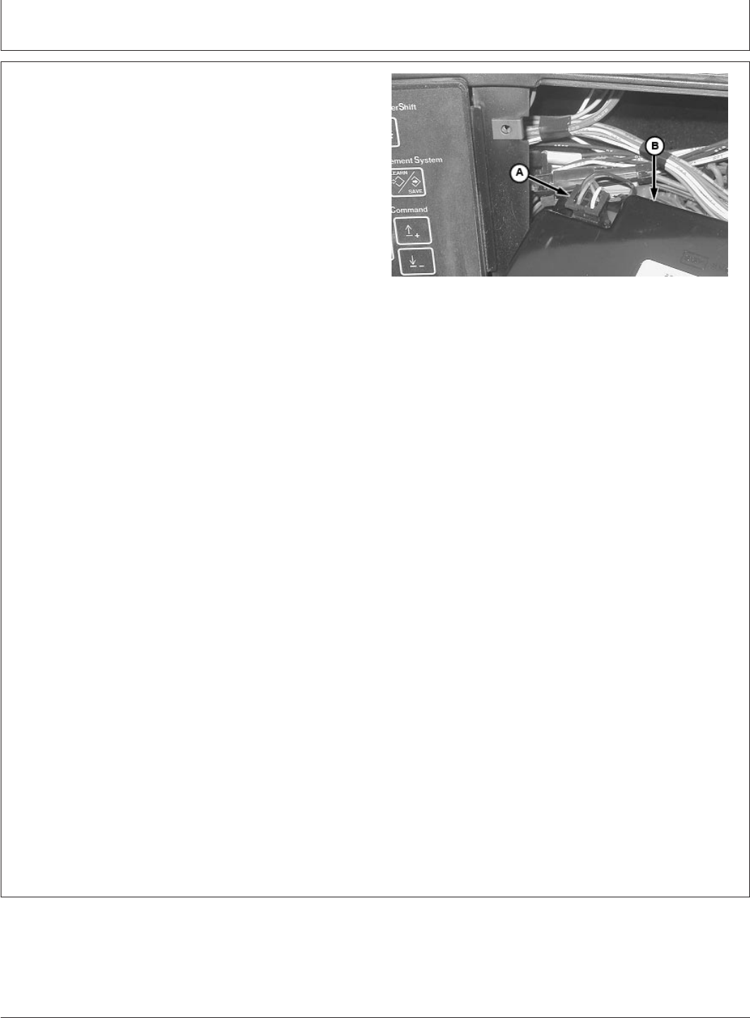
OUO6091,0001433 –19–14AUG01–19/27
PC6778 –UN–14AUG01
A—JDLINK SCV Connector
B—SCV Panel Wiring Harness Connector
NOTE: Reference JDLINK wiring harness at beginning of
instruction for CCD Bus connector.
30. Connect JDLINK SCV connector (B) to SCV panel
wiring harness connector (A).
Continued on next page
(09JAN02)
11
Installation Instructions
010902
PN=13
P R O O F P R O O F
Installation Instructions
OUO6091,0001433 –19–14AUG01–20/27
PC6969 –UN–19DEC01
A—CCD Bus Connector
B—SCV Panel
31. Connect JDLINK wiring harness CCD Bus connector
(A) to SCV panel (B).
32. Reconnect battery ground.
IMPORTANT: Avoid damage to machine, reinstall
machine enough to be moved but do
not fully reassemble until proper
operation of JDLINK is confirmed.
33. To properly confirm operation of JDLINK, move
machine to an open area so it has clear view of sky
horizon.
34. Shut off engine , set parking brake.
35. Reference JDLINK Machine Messenger’s Technical
Manual to force a contact from the machine to
confirm cell service.
NOTE: Machine must be turned to the RUN position for
five minutes before step 6 of 8 in the online Setup
Confirmation procedure of the machine and
controller.
36. Login to JDLINK website, go to Dealer Menu/Setup
New Device Wizard and follow online procedures,
which will include the input of machine and
controller’s serial number.
37. Confirm test data (i.e. time/date, map location,
machine’s engine hours and electronics system
information).
If data is correct reassemble machine, if data is
incorrect call 1-888-GRNSTAR.
38. Shut off engine, set parking brake and remove key.
Continued on next page
(09JAN02)
12
Installation Instructions
010902
PN=14
P R O O F P R O O F

Installation Instructions
OUO6091,0001433 –19–14AUG01–21/27
PC6766 –UN–28NOV01
A—Screw
B—SCV Panel Spacer
C—SCV Panel
NOTE: If equipped with JDLINK wiring harness skip to
step 47.
39. Reinstall SCV panel (C), panel spacer (B) and retain
with screw (A).
Continued on next page
(09JAN02)
13
Installation Instructions
010902
PN=15
P R O O F P R O O F
Installation Instructions
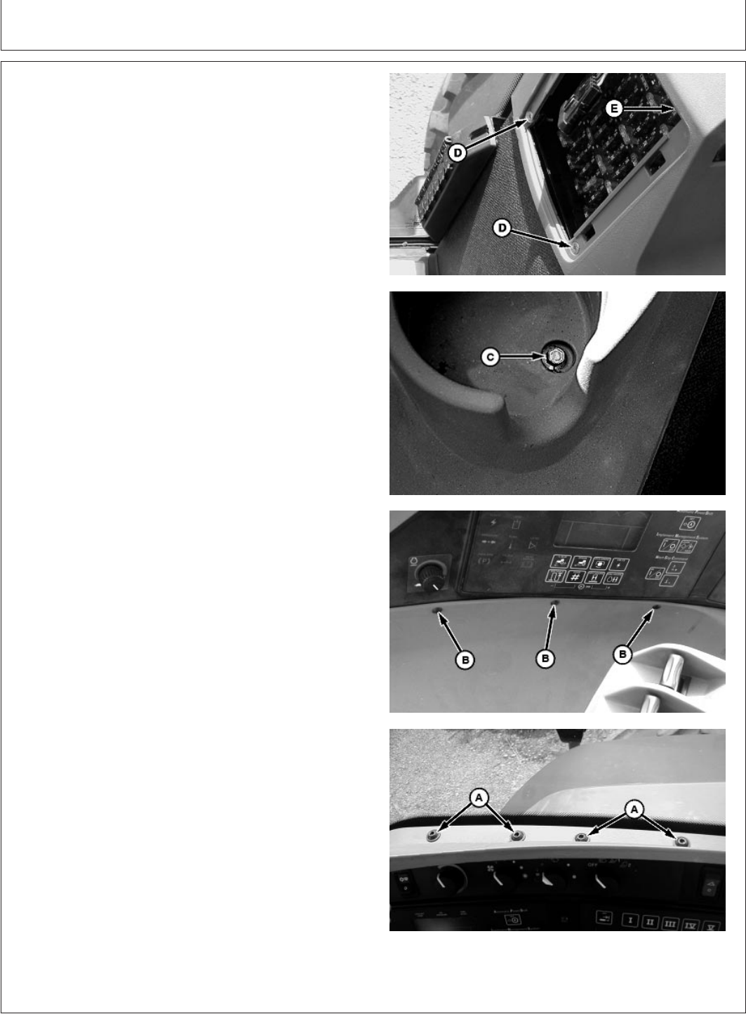
OUO6091,0001433 –19–14AUG01–22/27
PC6930 –UN–28NOV01PC6931 –UN–29NOV01PC6929 –UN–28NOV01PC6928 –UN–28NOV01
A—TORX Screws
B—Rivets
C—Cap Screw
D—Screws
E—Console
NOTE: After reinstallation of console, reinstall fuse panel
cover.
40. Reinstall console (E) and screws (D).
41. Reinstall cap screw (C) and new rivets (B).
42. Reinstall TORX screws (A).
(09JAN02)
14
Installation Instructions
010902
PN=16
P R O O F P R O O F
Continued on next page
Installation Instructions
OUO6091,0001433 –19–14AUG01–23/27
PC6933 –UN–28NOV01
A—Rear Window Molding
43. Reinstall rear window molding (A).
OUO6091,0001433 –19–14AUG01–24/27
PC6934 –UN–28NOV01
A—Screw
B—Light
C—Trim
D—Trim Screws
44. Reinstall headliner trim (D) retain with screws (C).
45. Reinstall light (B) and retain with screw (A).
OUO6091,0001433 –19–14AUG01–25/27
PC6764 –UN–14AUG01
A—Shroud Screws (2 used)
B—Corner Post Shroud
46. Reinstall right rear corner post shroud (B) retain with
shroud screws (A).
OUO6091,0001433 –19–14AUG01–26/27
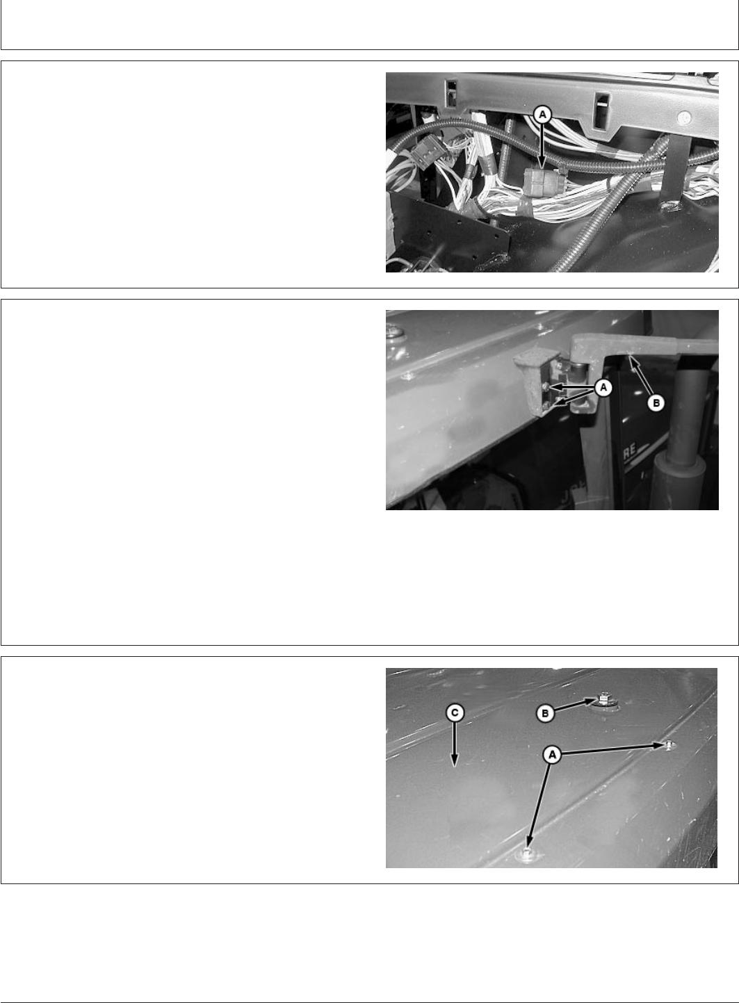
PC6763 –UN–14AUG01
A—Cap Screws and Washers (16 used)
B—Cap Screws and Washers (2 used)
NOTE: Reinstall radio antenna coax and rear lights
before installing cap screws.
47. Reinstall roof (C) and retain with washers and cap
screws (A and B).
(09JAN02)
15
Installation Instructions
010902
PN=17
P R O O F P R O O F
Continued on next page
Installation Instructions
OUO6091,0001433 –19–14AUG01–27/27
PC6762 –UN–14AUG01
A—Cap Screws
B—Mirror
48. Reinstall mirror (B) and retain with cap screws (A).
49. Reinstall STARFIRE receiver, if equipped.
(09JAN02)
16
Installation Instructions
010902
PN=18
P R O O F P R O O F