Deere and John Deere Intelligent Solutions Group VCA10001 User Manual Y40103UNIT
Deere & Company dba John Deere Intelligent Solutio Y40103UNIT
Contents
- 1. Instruction Manual
- 2. Revised Inst Manual
Instruction Manual

T184367
DeereTrax
VCA10023
INSTALLATION
INSTRUCTIONS
All
1600
C, F, U
John Deere Dubuque Works
DeereTrax (03FEB00)
ENGLISH
COPYRIGHT 2000
DEERE & COMPANY
Moline, Illinois
All rights reserved
A John Deere ILLUSTRUCTION
Manual
DeereTrax-19-03FEB00

Installation Instruction
DX,LIVE –19–25SEP92–1/1
LIVE WITH SAFETY
TS231 –19–07OCT88
Before returning machine to customer, make sure
machine is functioning properly, especially the safety
systems. Install all guards and shields.
DeereTrax (03FEB00)
1
Installation Instruction
020300
PN=3

Installation Instruction
CED,TX13067,2386 –19–02FEB99–1/2
PARTS LIST
Part numbers may change without notice.
Replacement parts are available through your John Deere
dealer.
•Installation Kit VCA10023
•VCA10000 Communications Controller Harness
•VCA10001 Communications Controller
•VCA10002 Power Harness
•VCA10003 LED Light Harness
•VCA10029 Cellular Antenna Whip and Ferrule
•VCU10028 Cellular Antenna Cable
•VCA10005 Antenna Mounting Bracket and Clamp
•VCU10008 GPS (Global Positioning System)
Antenna And Cable
•VCU10009 Alcohol Wipe
•VCU10010 Hook and Hook Fastener (Type 400)
•VCU10011 Hook and Hook Fastener (Type 250)
•VCU10012 Primer 97 (For Hook and Hook Fastener)
(3 used)
•VCU0013 Self Tapping Screw 6mm x 75mm (4 Used)
•VCU10014 Installation Instructions T184367
•VCU10017 U-bolt (2 used)
•VCU10019 Wire 16 ga. 12 ft.
•VCU10020 Convoluted Tubing 12 ft.
•VCU10022 6mm Lock Washer (4 used)
•VCU10031 Flat Washer Stainless Steel .250 in. (2
used)
•VCU10035 Cellular Antenna And Cable
•VCU10034 Cellular Antenna Cable
•AT180705 Ground Strap
•H159144 Grommets (3 used)
•R105388 Tie Band (25 used)
•T178552 Connectors (6 used)
•Heat Shrink Tubing T178552 (6 used)
•Template (Hole Location For Controller)
•14M7194 Nut Hex 6mm (2 used)
•14M7229 Nut Hex 5mm (3 used)
•14M7151 Nut Hex 8mm (2 used)
•19H1648 Cap Screw 3/8-16 x 3/4
•24M7138 Washer 5mm (3 used)
•24M3739 Washer 8mm (2 used)
•24M7105 Washer 6mm (2 used)
DeereTrax (03FEB00)
2
Installation Instruction
020300
PN=4
Continued on next page

Installation Instruction
CED,TX13067,2386 –19–02FEB99–2/2
•24H1136 Washer 5/16 x .734 x .065
•24H1622 Washer 3/8 x .870 x .083
•37H37 Self Tapping Screw 5/16 x 0.75
CED,TX13067,2662 –19–31JAN00–1/12
PARTS INCLUDED IN KIT
T128007B
T128007B –UN–
1—VCA10002 Power
Harness
POWER HARNESS
Continued on next page
DeereTrax (03FEB00)
3
Installation Instruction
020300
PN=5

Installation Instruction
CED,TX13067,2662 –19–31JAN00–2/12
T128008B
T128008B –UN–
1—VCA10000 2—VCA10003 LED Light
Communications Harness
Controller Harness
COMMUNICATIONS CONTROLLER AND LED
HARNESSES
Continued on next page
DeereTrax (03FEB00)
4
Installation Instruction
020300
PN=6
Installation Instruction
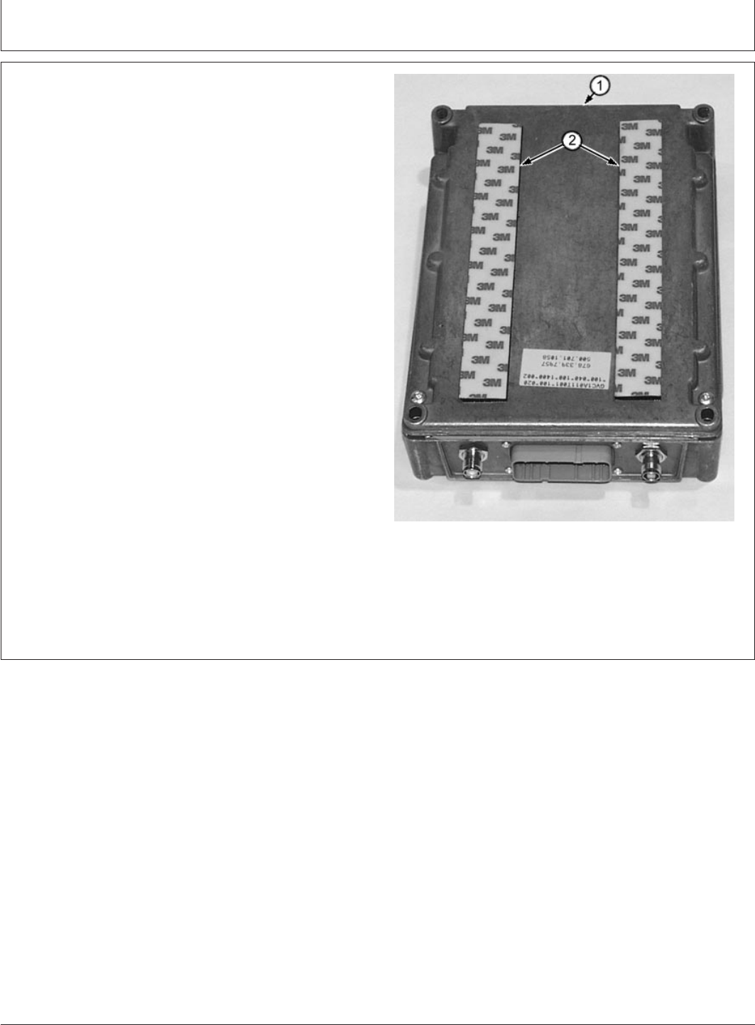
CED,TX13067,2662 –19–31JAN00–3/12
T127991B –UN–02FEB00
1—VCA10001 Communications Controller
2—VCU10010 and VCU10011 Hook and Loop
Fastener
COMMUNICATIONS CONTROLLER
Continued on next page
DeereTrax (03FEB00)
5
Installation Instruction
020300
PN=7
Installation Instruction
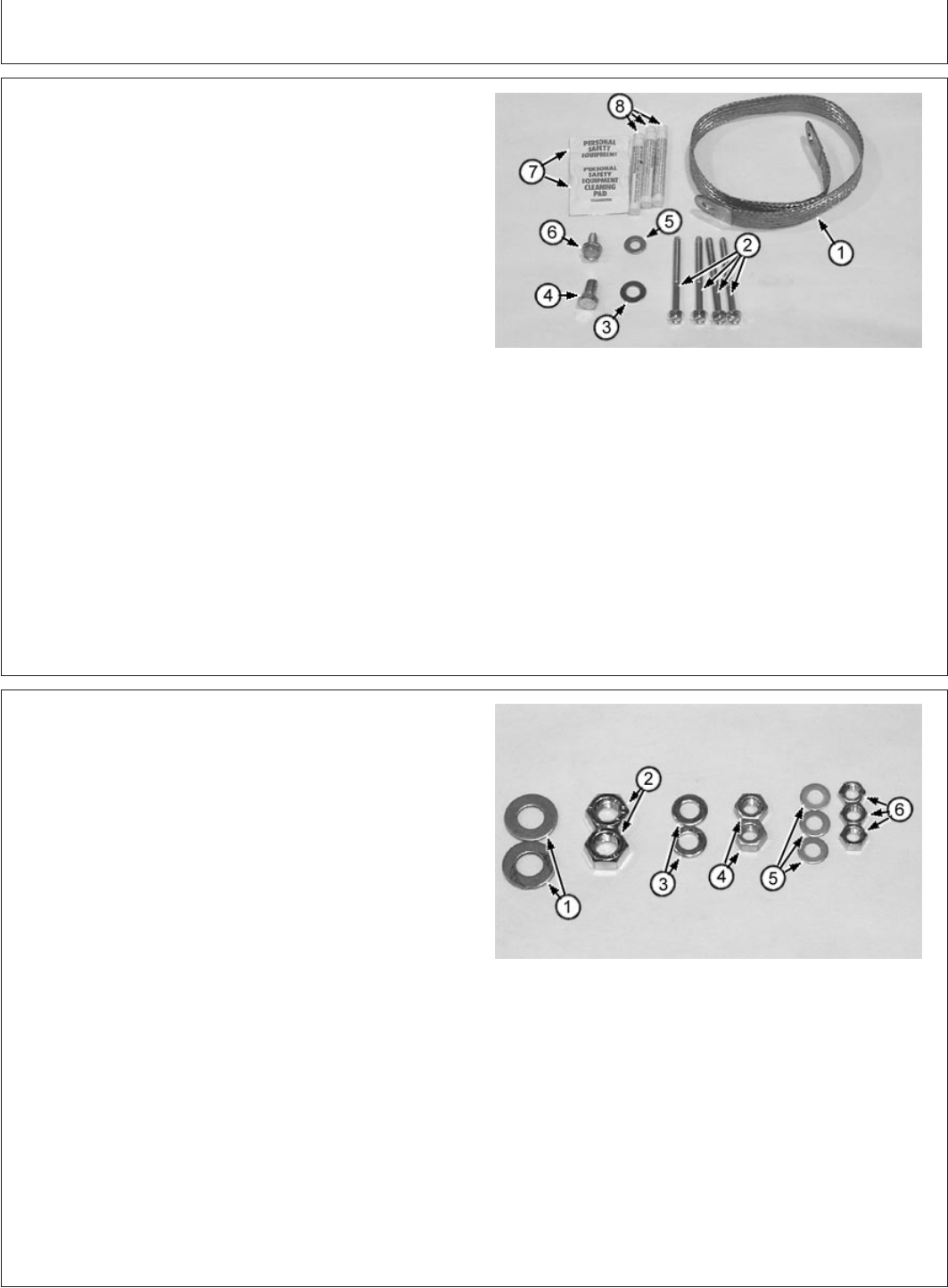
CED,TX13067,2662 –19–31JAN00–4/12
T127992B –UN–02FEB00
1—AT180705 Ground Strap
2—VCU10013 6mm x 75mm Self Tapping Screws
(4)
3—24H1622 Washer 3/8 x .870 .083
4—19H1648 Cap Screw 3/8-16 x 3/4
5—24H1136 Washer 5/16 x .734 x .065
6—37H37 5/16 x .75 Self Tapping Screw
7—VCU10009 Alcohol Wipe (2)
8—VCU10012 Primer 97 (3)
COMMUNICATIONS COMMUNICATOR MOUNTING
HARDWARE
CED,TX13067,2662 –19–31JAN00–5/12
T127993B –UN–02FEB00
1—24M3739 8mm Flat Washer (2)
2—14M7151 8mm Hex Nut (2)
3—24M7105 6mm Flat Washer (2)
4—14M7194 6mm Hex Nut (2)
5—24M7138 5mm Flat Washer (3)
6—14M7229 5mm Hex Nut (3)
ALTERNATOR HARDWARE
DeereTrax (03FEB00)
6
Installation Instruction
020300
PN=8
Continued on next page
Installation Instruction
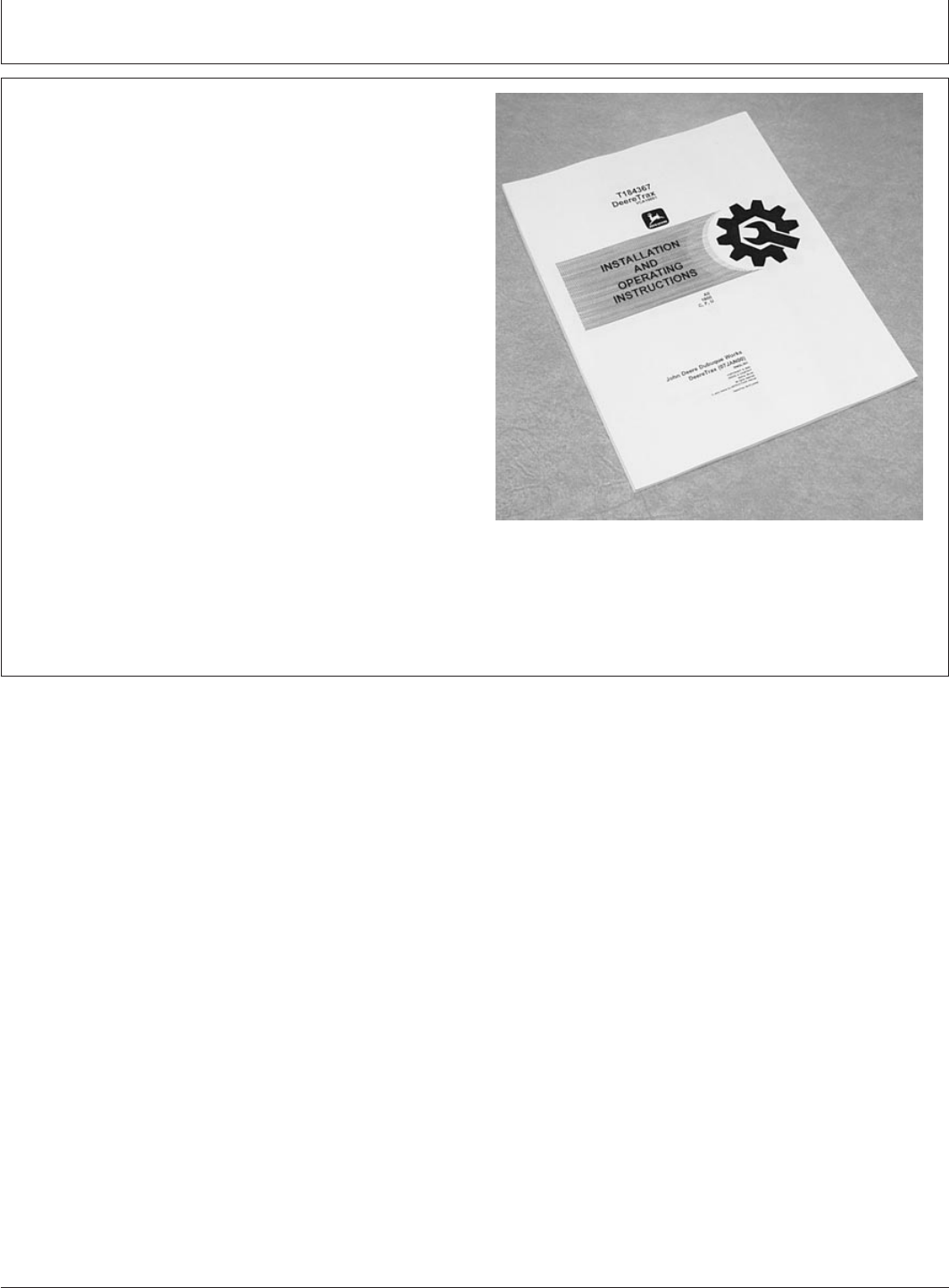
CED,TX13067,2662 –19–31JAN00–6/12
T128067B –UN–03FEB00
Installation and Operating Instructions
INSTALLATION AND OPERATING INSTRUCTIONS
Continued on next page
DeereTrax (03FEB00)
7
Installation Instruction
020300
PN=9
Installation Instruction
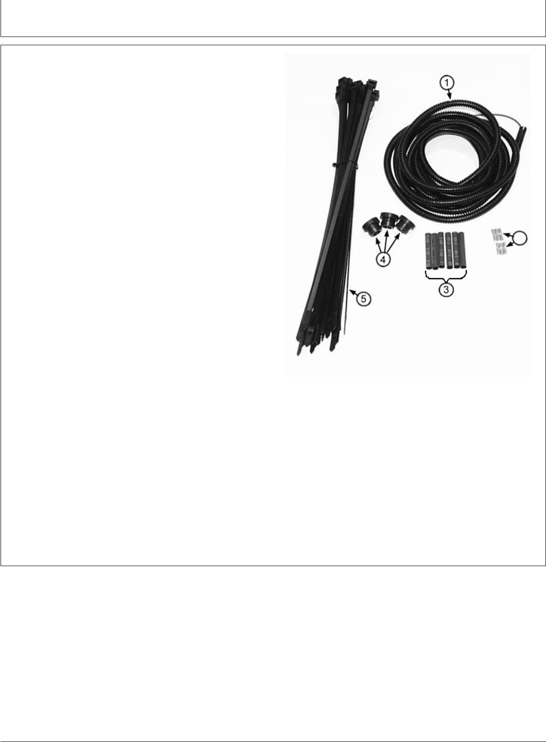
CED,TX13067,2662 –19–31JAN00–7/12
T127996B –UN–02FEB00
1—VCU10020 Convoluted Tubing and VCU10019
Wire
2—T178552 Connectors (6)
3—T178552 Heat Shrink Tubing (6)
4—AT159144 Grommet (3)
5—R105388 Tie Band (25)
HARNESS ROUTING HARDWARE
Continued on next page
DeereTrax (03FEB00)
8
Installation Instruction
020300
PN=10
Installation Instruction
CED,TX13067,2662 –19–31JAN00–8/12
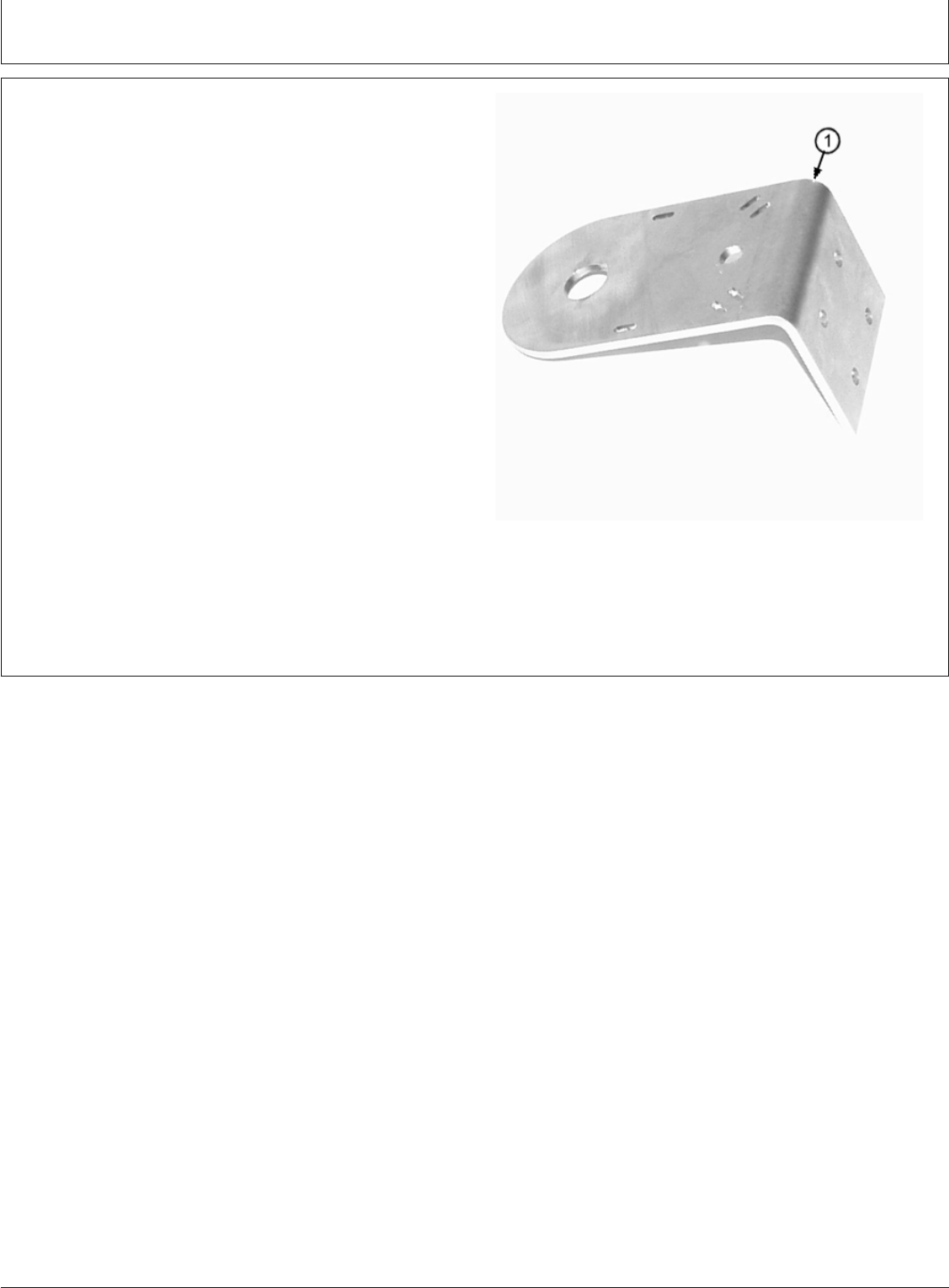
T128082B –UN–03FEB00
1—VCU10005 Antenna Mounting Bracket
ANTENNA MOUNT BRACKET
Continued on next page
DeereTrax (03FEB00)
9
Installation Instruction
020300
PN=11
Installation Instruction
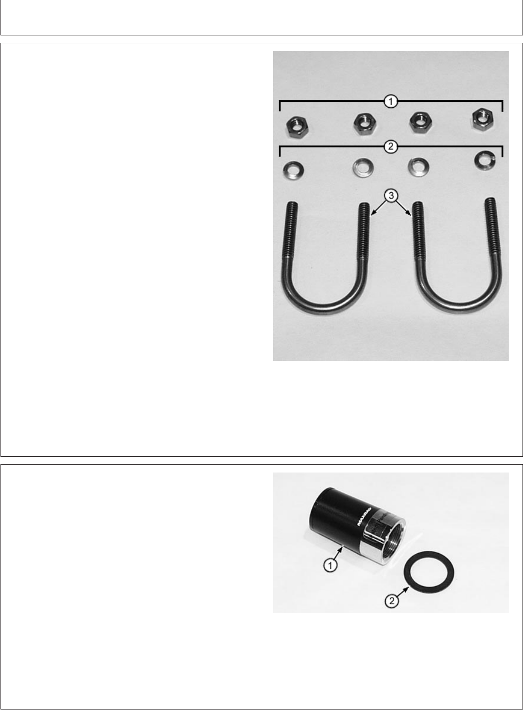
CED,TX13067,2662 –19–31JAN00–9/12
T128002B –UN–02FEB00
1—14H387 1/4-20 Hex Nut (4)
2—VCU10022 6mm Lock Washer (4)
3—VCU10017 U-Bolts (2)
ANTENNA MOUNTING U-BOLTS
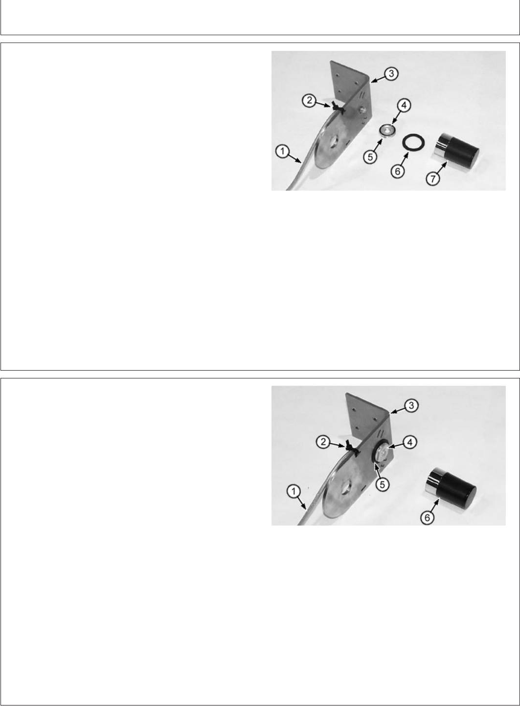
CED,TX13067,2662 –19–31JAN00–10/12
T127999B –UN–02FEB00
1—Antenna
2—Rubber Washer
CELLULAR ANTENNA
VCU10035 Cellular antenna includes all parts shown.
DeereTrax (03FEB00)
10
Installation Instruction
020300
PN=12
Continued on next page
Installation Instruction
CED,TX13067,2662 –19–31JAN00–11/12
T128068B –UN–03FEB00
1—Cable
2—Nut
3—O-Ring
CELLULAR ANTENNA CABLE
VCU10034 Cellular antenna cable includes all parts
shown.
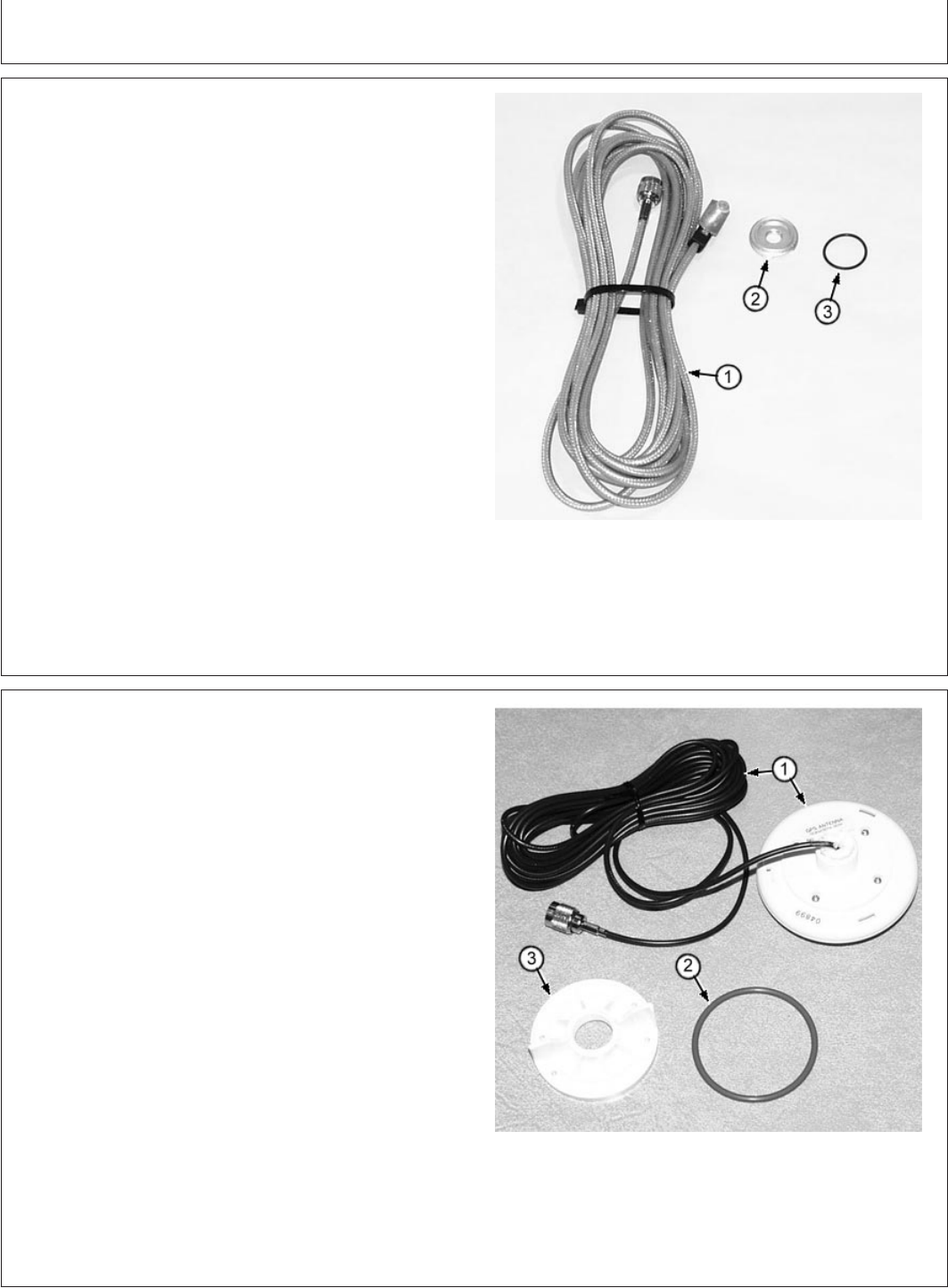
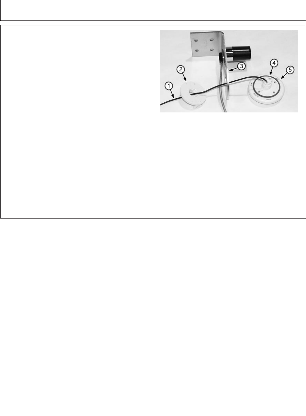
CED,TX13067,2662 –19–31JAN00–12/12
T128001B –UN–02FEB00
1—Antenna and cable
2—O-Ring
3—Nut
GPS ANTENNA AND CABLE
VCU10008 GPS antenna includes all parts shown.
DeereTrax (03FEB00)
11
Installation Instruction
020300
PN=13

Installation Instruction
CED,TX13067,2455 –19–03AUG99–1/1
TOOLS AND EQUIPMENT
Not Supplied With Kit
•Drill Bits
•#4 or 7/32 in.
•17/64 in.
•3/8 in.
•1/2 in.
•3/4 in.
•Uni-Bit
•Volt-Ohmmeter
•Electric Drill
•Duct Tape
•Electrical Tape
•Screw Drivers
•Metric and SAE Wrenches
•Fish Tape
•Utility Knife
•Wire Crimping Tool
•Weatherpack Tool JDG364
CED,TX13067,2452 –19–03AUG99–1/1
CUSTOMER SUPPORT CENTER
The Customer Support Center will assist dealers or
customers having problems installing or operating.
Customer Support Center phone number:
1-800-939-0805.
DeereTrax (03FEB00)
12
Installation Instruction
020300
PN=14

Installation Instruction
CED,TX13067,2453 –19–03AUG99–1/1
CUSTOMER PERSONAL SERVICE (CPS)
Note to customer:
CPS will be used to gain access to your vehicle’s
information via the Internet through the Deere Web Site at
http://cps.deere.com
CED,TX13067,2454 –19–03AUG99–1/1
CELLULAR PHONE SERVICE
DeereTrax communicates via a built-in cellular phone.
The unit is pre-programmed at the factory and will be
activated when it is shipped to the dealer. If problems
arise, contact the Customer Support Center at
1-800-939-0805.
DeereTrax (03FEB00)
13
Installation Instruction
020300
PN=15
Installation Instruction
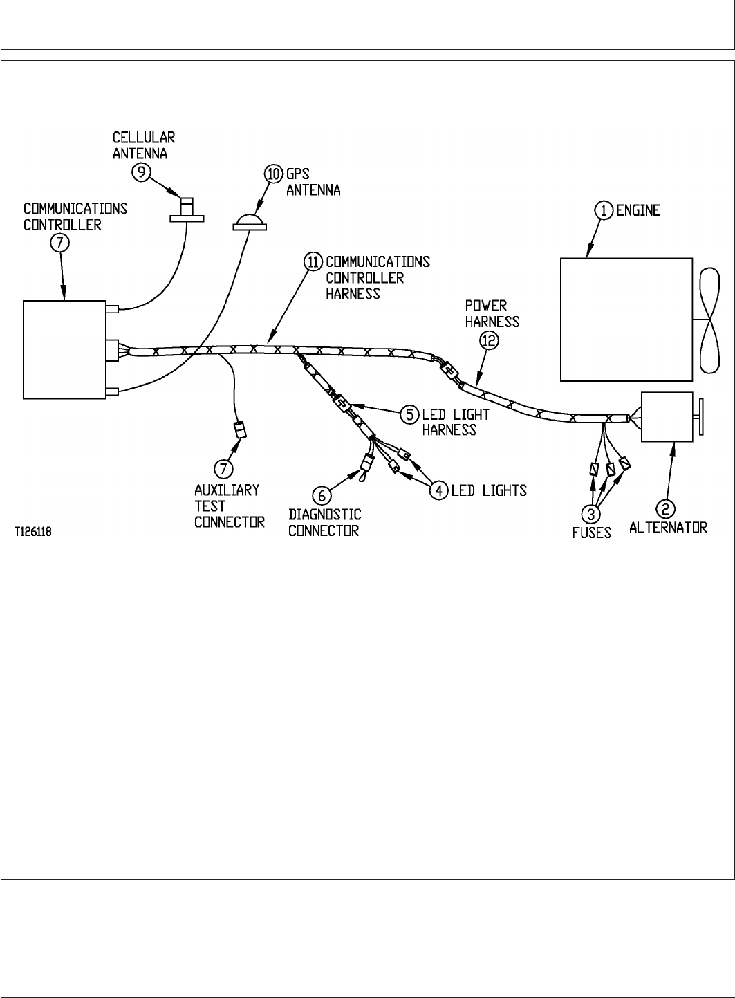
CED,TX13067,2596 –19–19NOV99–1/1
BASIC SYSTEM LAYOUT
T126118 –19–02FEB00
1—Engine 5—Diagnostic Connector 8—Cellular Antenna 11—Power Harness
2—Alternator 6—Auxiliary Connectors 9—GPS Antenna
3—Fuses 7—Communications 10—Communications
4—LED Lights Controller Harness
Basic components of the system are:
1. Antennas and antenna cables
2. Harnesses
3. Communications controller
Before installation is started, read this instruction.
Find the best location for each component.
Follow guidelines to prevent components from
becoming damaged during machine operation.
Make sure components are close enough to
communications controller so cables will reach.
DeereTrax (03FEB00)
14
Installation Instruction
020300
PN=16
Installation Instruction
CED,TX13067,2458 –19–03AUG99–1/1
SELECTING MOUNTING LOCATION FOR
COMMUNICATIONS CONTROLLER
T127567B –UN–22JAN00
IMPORTANT: Before doing any work on an electrical
component, turn battery disconnect
switch OFF or disconnect negative
battery cable. Damage to electrical
components may result if terminals are
shorted during maintenance.
Never install close to the engine,
transmission or hydraulic tank where
temperature may exceed 70°C (160°F).
Never install on a panel that vibrates
excessively. Controller damage may
result if exposed to excessive heat or
vibration.
•Install communications controller in a protected area
where it won’t be exposed to excessive heat or damage
from chains or tools carried in the cab. The load center
area of a 4-wheel drive loader is an ideal location.
•Avoid installation in areas where temperature can
exceed 70°C (160°F). Typical areas to avoid are inside
the engine compartment, next to a hydraulic tank or
transmission.
•Select a location so harness connectors and antenna
cables can be attached or removed easily.
•Do not install in a location that will prevent removal of
other components.
•Install controller horizontally or with connectors down to
prevent water or oil from collecting in harness
connections.
•Before final location is chosen, check power harness
length and antenna cable length.
DeereTrax (03FEB00)
15
Installation Instruction
020300
PN=17
Installation Instruction
CED,TX13067,2600 –19–22NOV99–1/4
INSTALLING COMMUNICATIONS
CONTROLLER
Communications controller can be installed using hook
and hook fastener or using cap screws. Choose the best
procedure for your application.
CED,TX13067,2600 –19–22NOV99–2/4
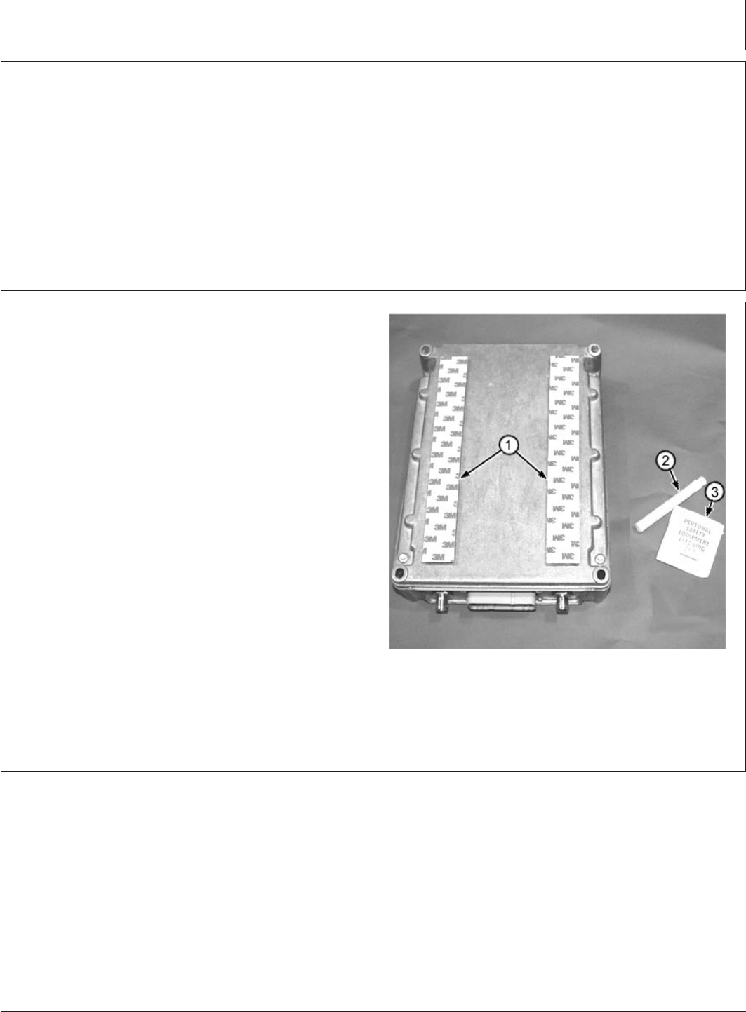
T126195B –UN–24NOV99
1—Hook and Hook Clear Strips
2—VCU10012 Primer 97
3—VCU10009 Alcohol Wipe
INSTALLING COMMUNICATIONS CONTROLLER
USING HOOK AND HOOK FASTENER
1. Communications controller already has hook and hook
fastener attached.
2. Clean installation area of machine using VCU10009
alcohol wipe (3) then apply VCU10012 Primer 97 (2),
to the cleaned area. Follow directions on primer tube.
3. Remove clear strips (1) from hook and hook fastener
and press communications controller firmly into place.
Continued on next page
DeereTrax (03FEB00)
16
Installation Instruction
020300
PN=18
Installation Instruction
CED,TX13067,2600 –19–22NOV99–3/4
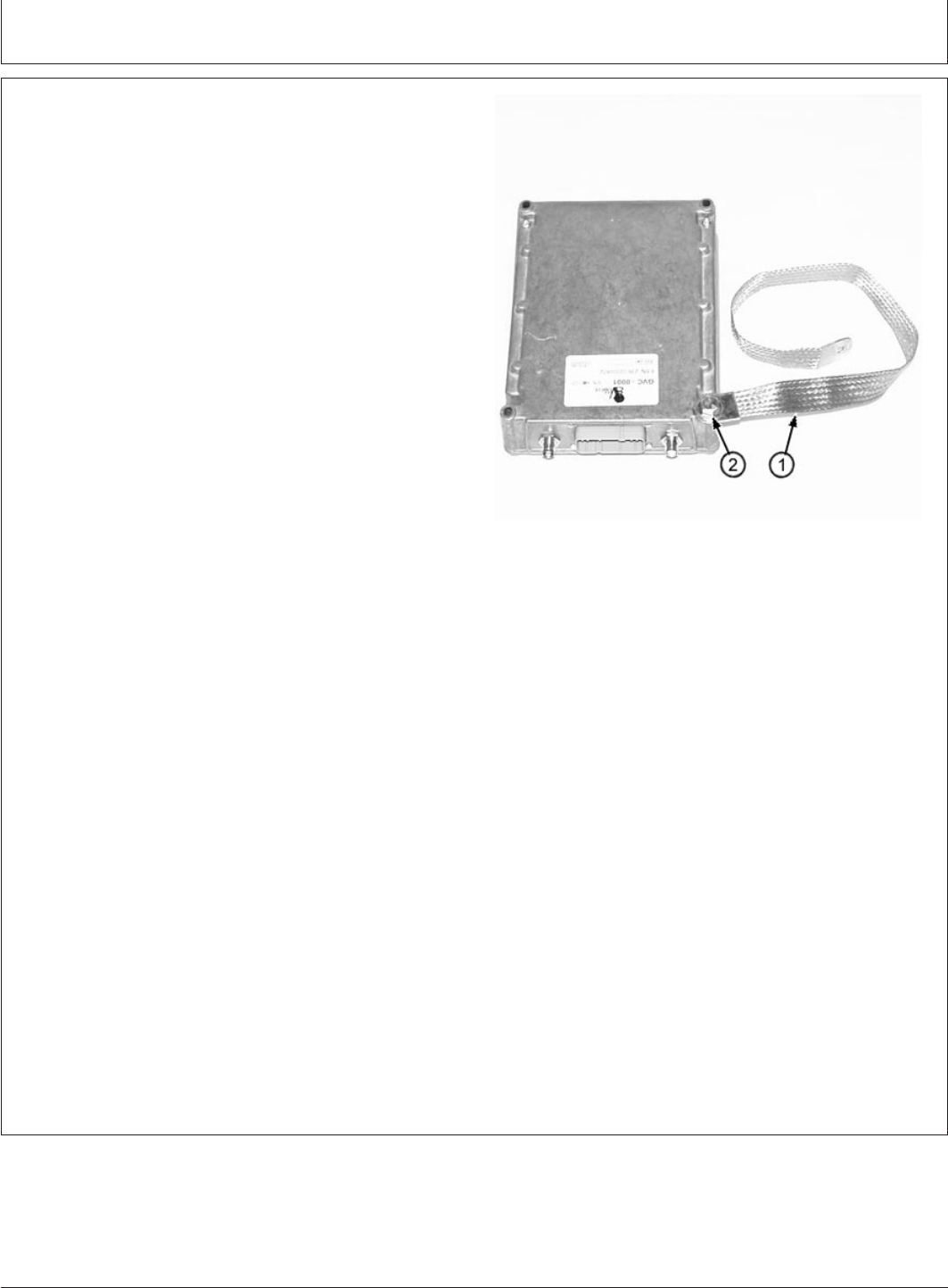
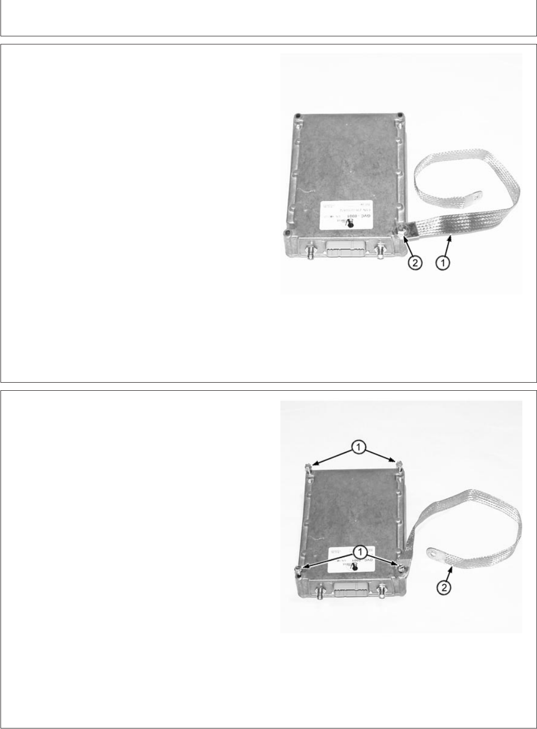
T127567B –UN–22JAN00
1—AT180705 Ground Strap
2—19H1648 Cap Screw
4. One hole in the communications controller has internal
threads. Install Capscrew (2) to attach Ground Strap
(1).
5. Attach other end of ground strap (1) to a good clean
ground connection on the machine.
CED,TX13067,2600 –19–22NOV99–4/4
T127570B –UN–01FEB00
1—VCU10013 6mm x 75 Self Tapping Cap Screw
(4 used)
2—AT180705 Ground Strap
INSTALLING COMMUNICATIONS CONTROLLER
USING CAP SCREWS
1. Choose a mounting area using guidelines in Selecting
Mounting Location For Communications Controller.
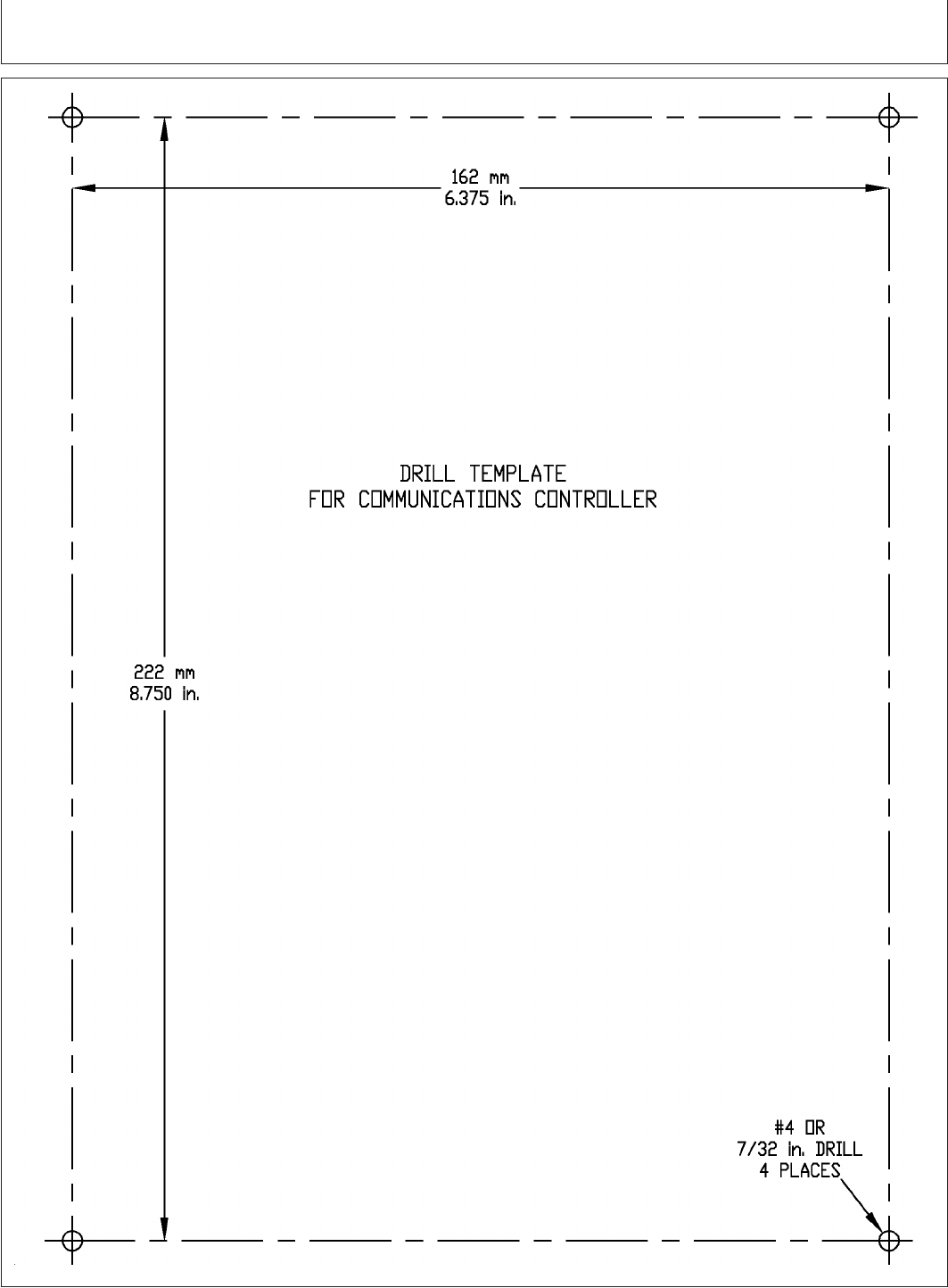
2. Use template to locate mount holes. (See Drill
Template For Communications Controller on next
page)
3. Drill mount holes using a No. 4 or 7/32 bit.
4. Install Self-tapping cap screws (1). Use one screw to
attach ground strap (2).
5. Attach other end of ground strap to a good clean
ground connection on the machine.
DeereTrax (03FEB00)
17
Installation Instruction
020300
PN=19
Installation Instruction
CED,TX13067,2601 –19–22NOV99–1/1
T126134 –19–24NOV99
DeereTrax (03FEB00)
18
Installation Instruction
020300
PN=20

Installation Instruction
CED,TX13067,2664 –19–02FEB00–1/1
REMOVING COMMUNICATIONS
CONTROLLER
1. To remove the communications controller after
installing with the hook and hook fastener:
a. Carefully pry controller from mounting surface
starting at a corner. To prevent hook and hook
fastener from pulling away from controller, push
your finger between the fastener pieces.
b. If hook and hook fastener pulls loose from the
controller, press it back in place.
2. To reinstall the controller, align hook and hook fastener
strips on controller and mounting surface, then press
controller against one end of the fastener strips and
“rock” into full contact.
Slowly apply pressure along full length of controller
until fasteners are secure.
DeereTrax (03FEB00)
19
Installation Instruction
020300
PN=21
Installation Instruction
CED,TX13067,2599 –19–22NOV99–1/2
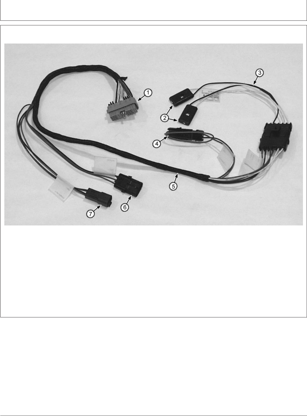
INSTALLING COMMUNICATIONS CONTROLLER HARNESS
T128057B –UN–03FEB00
1—Connector to 2—LED Lights 5—Communications 7—4-Pin Connector to
Communications 3—LED Light Harness Controller Harness Power Harness
Controller 4—Diagnostic Connector 6—Auxiliary Connectors
1. Route communications controller harness so the
LED lights (4) and diagnostic connector (5) are
protected from damage and yet accessible. LED
lights and diagnostic connector will be used for
troubleshooting the system.
Continued on next page
DeereTrax (03FEB00)
20
Installation Instruction
020300
PN=22
Installation Instruction
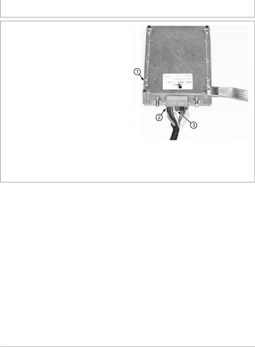
CED,TX13067,2599 –19–22NOV99–2/2
T127585B –UN–22JAN00
1—Communications Controller
2—Communications Controller Connector
3—Cap Screw
2. Push communications controller harness 30-pin
connector (2) onto communications controller (1) so
pins are started.
Use a 1/4 in. socket to tighten cap screw (3).
3. Using tie bands, attach extra connectors to the
communications controller harness so they won’t be
damaged during normal operation.
DeereTrax (03FEB00)
21
Installation Instruction
020300
PN=23
Installation Instruction
CED,TX13067,2550 –19–26OCT99–1/5
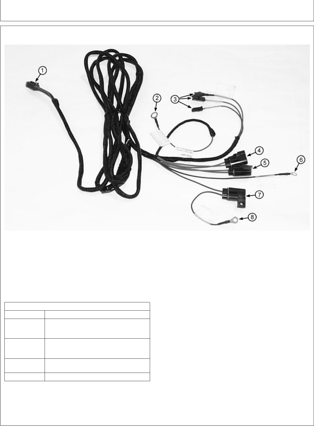
INSTALLING POWER HARNESS
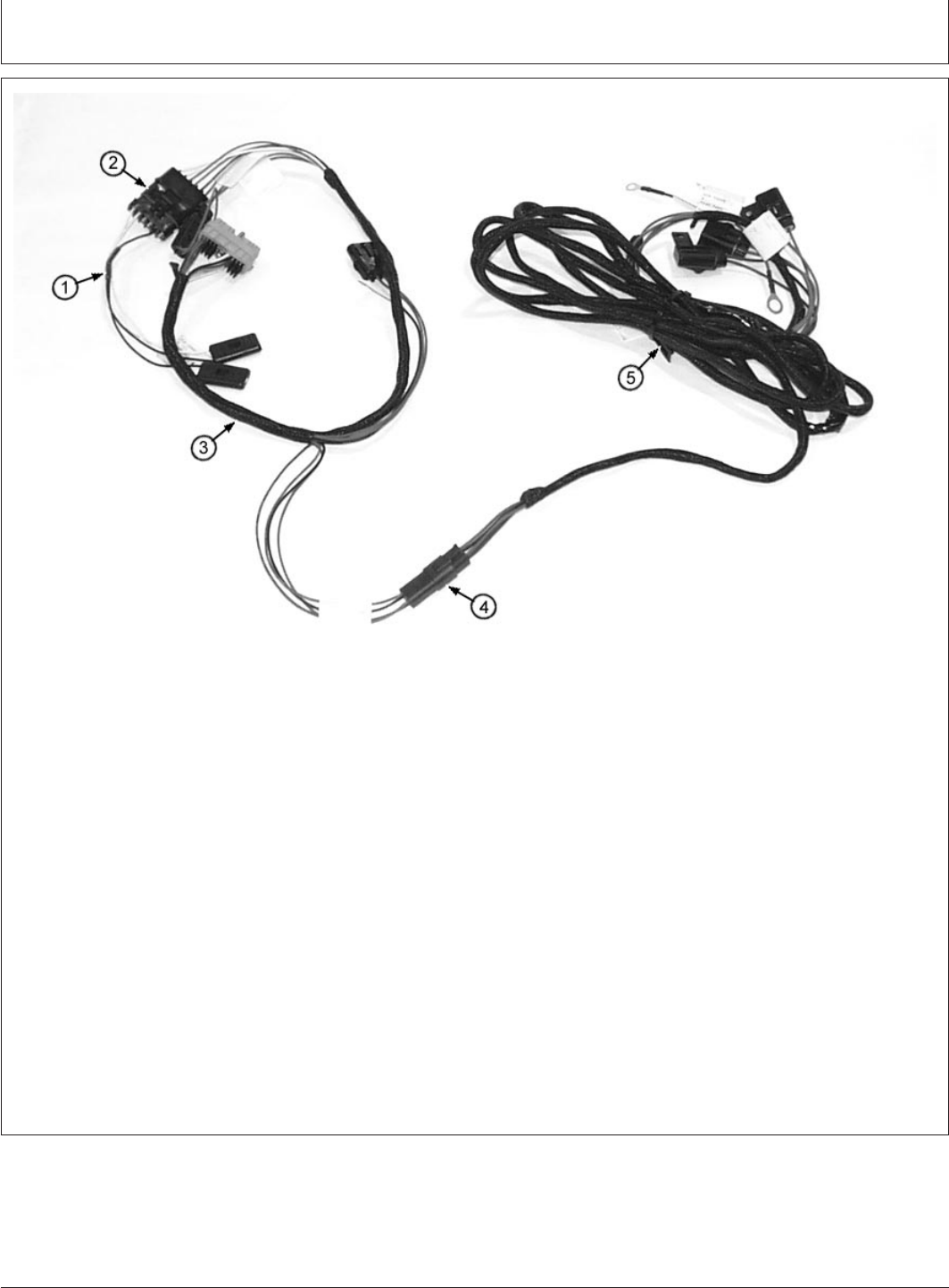
T128061B –UN–03FEB00
VCA10002 Power Harness
1—4-pin Connector to 4—B+ Unswitched Power 8—D+ Switched Power
Communications Fuse (Brown Wire)
Controller 5—W+/R+ Engine Running
2—B+ Unswitched Power Fuse
(Red Wire) 6—GND (Ground) (Black
3—W+/R+ Engine Running Wire)
(Purple Wire) 7—D+ Switched Power
Connectors (Use Fuse
whichever needed)
Power Harness Electrical Requirements
Wire Color Machine Connection
Red Constant positive (+) power source. 12—24
volts typical, 36 volts maximum. With key ON
or OFF
Brown Positive (+) power source. 12—24 volts typical,
36 volts maximum. Only with key ON (0 volts
with key OFF.).
Purple Positive (+) power source. 6—24 volts typical,
36 volts maximum. With engine running.
Black Ground (GND)
DeereTrax (03FEB00)
22
Installation Instruction
020300
PN=24
Continued on next page
Installation Instruction
CED,TX13067,2550 –19–26OCT99–2/5
CONNECTING B+ UNSWITCHED POWER (RED
WIRE)
CAUTION: Before doing any electrical
maintenance, turn battery disconnect switch
OFF or disconnect negative (-) battery cable.
Damage to electrical components or
personal injury could result if a power wire
is shorted to ground.
This connection supplies battery voltage to the
communications controller regardless of key switch
position.
Typical connection for unswitched power is B+ terminal
on the alternator.
If connecting B+ Red wire terminal to an existing
machine wire, use VCU10018 Connector and T178552
Heat Shrink Tubing.
CONNECTING D+ SWITCHED POWER (BROWN
WIRE)
This connection supplies switched power to the
communications controller.
Connect to a place where battery power is present
with the key switch ON and not present with the key
switch OFF.
Typical connection for switched power is D+ terminal
on the alternator.
1. Connect D+ Brown to switched power source. If
splicing into existing machine wire, use VCU10018
Connector and T178552 Heat Shrink Tubing.
2. If alternator does not have a D+ terminal, locate
another source for switched power.
Use a VCU10018 butt splice to connect to an
existing wire or terminal.
Cover splice with heat shrink tubing to prevent
shorting to ground.
CONNECTING GROUND (GND) (BLACK WIRE)
This connection provides a ground for the system.
Connect Black Ground wire to alternator case or
machine frame.
CONNECTING W+/R+ ENGINE RUNNING (PURPLE
WIRE)
This connection provides the communications
controller with a signal indicating the engine is running.
A minimum of 6 volts is required.
Typical source for this signal is the W+ or R+ terminal
on the alternator. This provides a signal when the
engine is running.
Three W+/R+ Purple wires are included in the harness,
each has a different connector. Choose the one that
fits your alternator. Tie the other Purple wires to the
harness so they won’t be damaged during normal
operation.
If Machine Has: Connect Purple Wire To:
W+ terminal on alternator W+ alternator terminal
R+ terminal on alternator R+ alternator terminal
If alternator does not have Switched power source
above terminals
Continued on next page
DeereTrax (03FEB00)
23
Installation Instruction
020300
PN=25
Installation Instruction
CED,TX13067,2550 –19–26OCT99–3/5
T128062B –UN–03FEB00
LED Light Harness, Communications Controller Harness and Power Harness
1—VCA10003 LED Light 3—VCA10001 4—4-pin Connector
Harness Communications 5—VCA10002 Power
2—6-pin Connector Controller Harness Harness
CONNECTING AND ROUTING HARNESSES TO
COMMUNICATIONS CONTROLLER
1. IMPORTANT: Route harnesses away from hot,
moving or vibrating components.
Do not attach harnesses to
hydraulic hoses. Avoid sharp
edges and use grommets and tie
bands where needed.
Route communications controller harness to
communications controller mounting location. Use tie
bands to secure harnesses to existing harnesses
where possible.
2. Connect LED light harness 6-pin connector (2) to
communications controller harness.
3. Connect power harness 4-pin connector (4) to
communications controller harness 4-pin connector.
Continued on next page
DeereTrax (03FEB00)
24
Installation Instruction
020300
PN=26
Installation Instruction
CED,TX13067,2550 –19–26OCT99–4/5
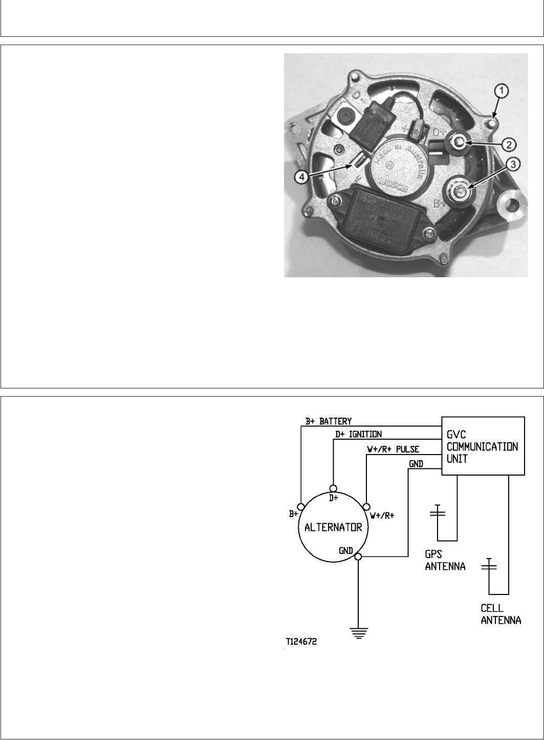
T125448B –UN–27OCT99
Typical Alternator Terminals
1—GND Terminal
2—D+ Terminal
3—B+ Terminal
4—W Terminal
TYPICAL CONNECTIONS TO AN ALTERNATOR
Shown are typical connections to a Bosch alternator.
Terminal location on your alternator may be different, but
they should be marked the same.
CED,TX13067,2550 –19–26OCT99–5/5
T124672 –19–09DEC99
Typical Connection To Alternator
1. Connect B+ Red wire to B+ terminal on alternator.
2. Connect D+ Brown wire to D+ alternator terminal.
3. Connect GND Black wire to alternator case or machine
frame.
4. Connect W+/R+ Purple wire to W+ or R+ alternator
terminal.
5. Use tie bands to secure harnesses to existing
harnesses where possible.
DeereTrax (03FEB00)
25
Installation Instruction
020300
PN=27
Installation Instruction
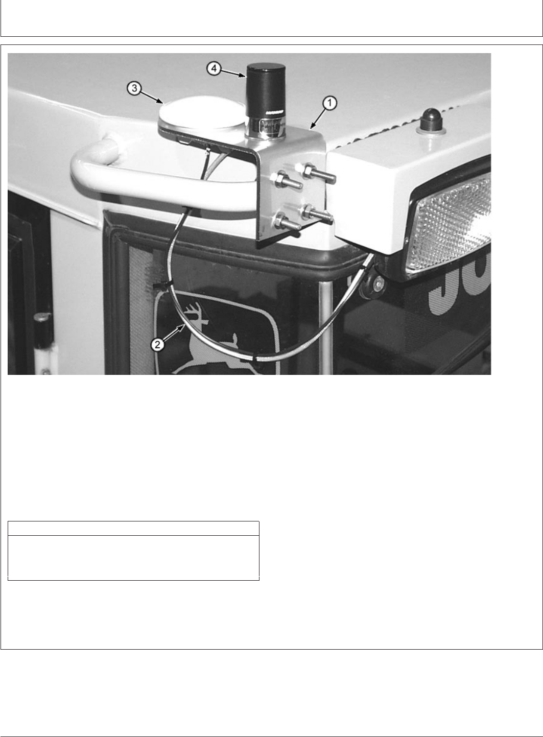
CED,TX13067,2597 –19–19NOV99–1/2
SELECTING MOUNTING LOCATION FOR ANTENNAS
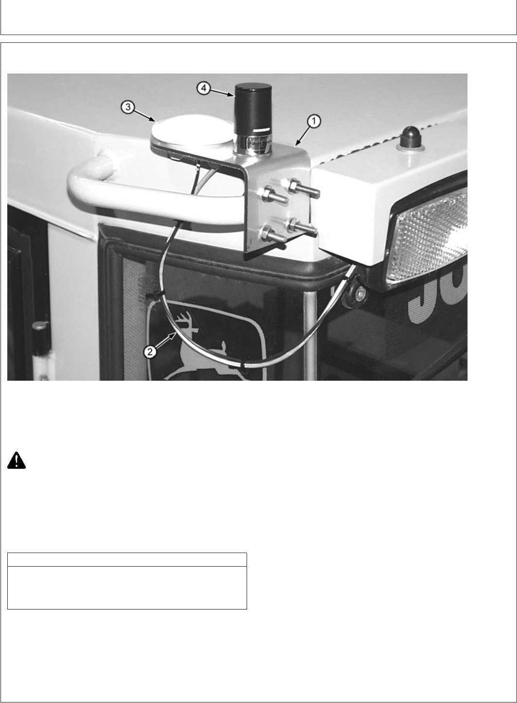
T128018B –UN–02FEB00
1—VCA10005 Antenna 3—VCU10008 GPS Antenna
Mounting Bracket 4—VCU10034 Cellular
2—Drip Loop in Antenna Antenna
Cables
CAUTION: Never modify by drilling or
welding a Roll Over Protection Structure
(ROPS). Structure may fail during a roll over
accident.
The Falling Objects Protection Structure
(FOPS) may be modified by drilling holes up
to 25mm (1.0 in.) diameter.
FCC Antenna Warning Label
While the device is in operation, a separation of at least 500 mm
(20 in.) must be maintained between antennae and the body of
the user or nearby persons in order to meet the FCC RF
exposure guidelines.
•Antennas must be mounted outside the cab at least
500 mm (20 in.) away from the machine operator.
•Cellular antenna should be mounted using
VCA10005 mounting bracket if possible.
•Entire length of cellular antenna must be mounted
above cab roof or any structure within 300 mm (12
in.).
•Mount cellular antenna (4) at least 300mm (12 in.)
from upright metallic structures, like mirrors. Center
of the cab roof or attached to a roof handhold is an
ideal location.
•Mount the GPS antenna (3) in an area that allows
an unobstructed view of the sky. Mounting near the
cellular antenna is OK. Use Antenna Mounting
Bracket (1) when possible.
DeereTrax (03FEB00)
26
Installation Instruction
020300
PN=28
Continued on next page

Installation Instruction
CED,TX13067,2597 –19–19NOV99–2/2
•Antennas may be mounted directly to a cab or
ROPS roof. Ensure all gaskets and O-Rings are
installed under antennas to prevent water entry.
Petroleum jelly may be used to prevent O-Rings
from slipping out of position.
Ensure adaquate ground plane is available (See
Installing Antennas Through Machine or Metal
Panel).
•Where antenna cables go through the roof or steel
panels, install convoluted tubing or grommets to
prevent chaffing or shorting. Make “drip loops” (2) in
cables to prevent water from running down the
cables and into the cab.
•Mount antennas where they are best protected from
damage.
•Antenna height must not exceed overall height
limitations for transporting the machine.
•Route antenna cables with existing cables or
harnesses.
DeereTrax (03FEB00)
27
Installation Instruction
020300
PN=29
Installation Instruction
CED,TX13067,2552 –19–27OCT99–1/6
ASSEMBLING ANTENNAS USING MOUNTING BRACKET
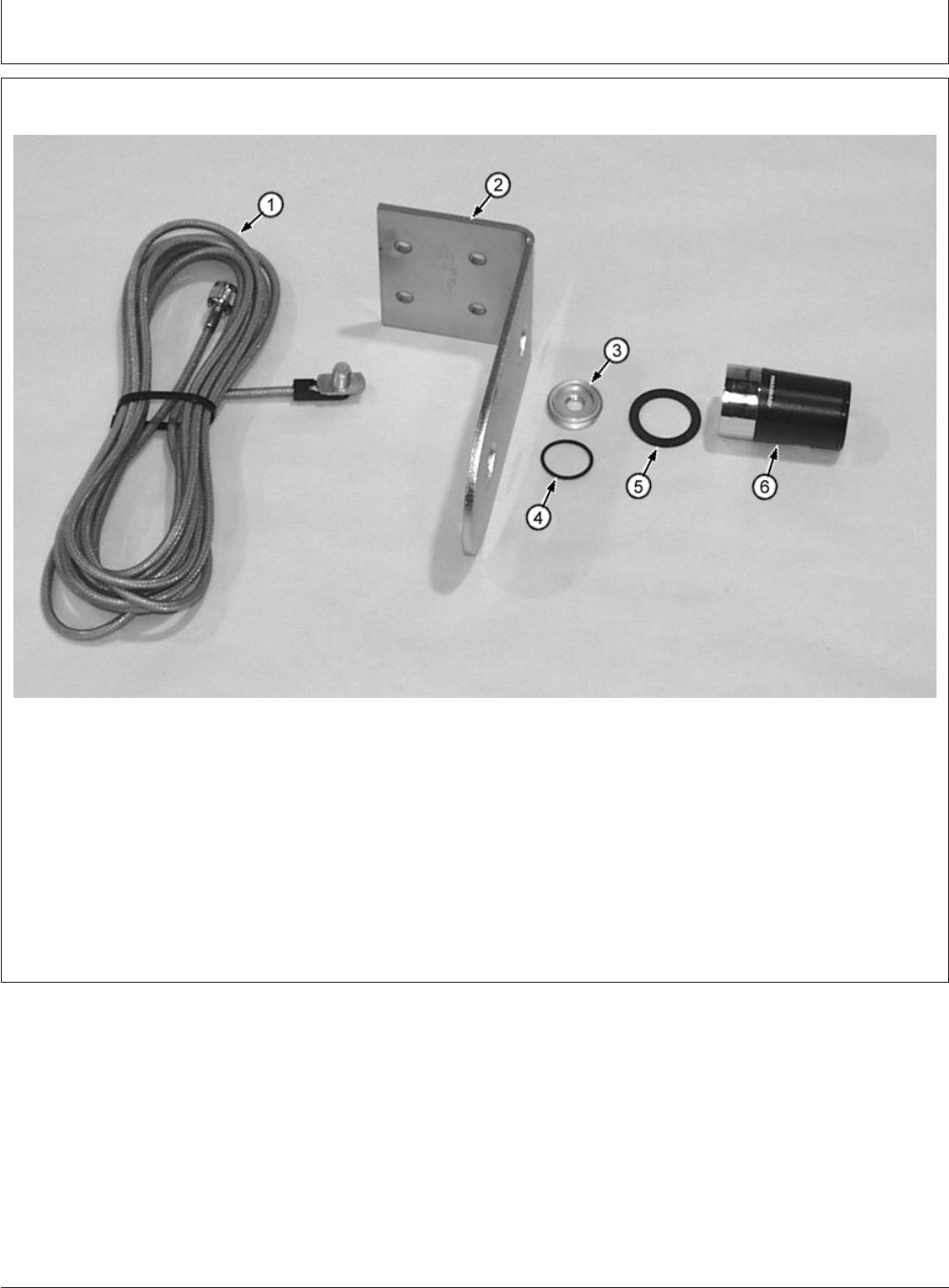
T128019B –UN–02FEB00
1—VCU10034Cellular 3—Nut 7—Spacer
Antenna Cable 4—O-ring
2—VCA10005 Antenna 5—Rubber Washer
Mounting Bracket 6—Cellular Antenna
Continued on next page
DeereTrax (03FEB00)
28
Installation Instruction
020300
PN=30
Installation Instruction
CED,TX13067,2552 –19–27OCT99–2/6
T128081B –UN–03FEB00
1—VCU10034 Cellular Antenna Cable
2—Tie Band
3—VCA10005 Antenna Mounting Bracket
4—O-ring
5—Nut
6—Rubber Washer
7—VCU10035 Cellular Antenna
ASSEMBLING CELLULAR ANTENNA
1. Insert cable end (1) through small hole in bracket (3).
2. Use tie bands (2) to attach cable to bracket.
CED,TX13067,2552 –19–27OCT99–3/6
T128075B –UN–03FEB00
1—VCU10034 Cellular Antenna Cable
2—Tie Band
3—VCA10005 Antenna Mounting Bracket
4—Nut
5—Rubber Washer
6—VCU10035 Cellular Antenna
3. Screw nut (4) over cable end. Apply petroleum jelly to
O-ring to ensure it stays in groove.
4. Apply petroleum jelly to rubber washer to prevent it
from rolling. Install rubber washer (5) over nut (4).
Screw antenna (6) onto nut. Hand tighten only.
DeereTrax (03FEB00)
29
Installation Instruction
020300
PN=31
Continued on next page
Installation Instruction
CED,TX13067,2552 –19–27OCT99–4/6
T128020B –UN–02FEB00
1—Cable
2—Nut
3—VCU10005 Antenna Mounting Bracket
4—O-Ring
5—VCU10008 GPS Antenna
ASSEMBLING GPS ANTENNA
1. Pass cable (1) through O-ring (4), Bracket (3) and Nut
(2). Screw nut onto antenna, ensure O-ring stays in
step on antenna.
2. Secure antenna cables as needed.
3. Install additional tie bands on cables as needed to
keep them neatly together.
Continued on next page
DeereTrax (03FEB00)
30
Installation Instruction
020300
PN=32
Installation Instruction
CED,TX13067,2552 –19–27OCT99–5/6
T128018B –UN–02FEB00
Typical Bracket Mount
1—VCU10005 Antenna 3—VCU10008 GPS Antenna
Mounting Bracket 4—VCU10035 Cellular
2—Drip Loop in Antenna Antenna
Cables
4. Attach bracket and antennas to hand hold or other
suitable location using U-bolts.
Mount cellular antenna (4) at least at least 300 mm
(12 in.) from upright structures like mirrors.
FCC Antenna Warning Label
While the device is in operation, a separation of at least 500 mm
(20 in.) must be maintained between antennae and the body of
the user or nearby persons in order to meet the FCC RF
exposure guidelines.
Mount antenna at least 500 mm (20 in.) from
operators body.
5. Make a drip loop (2) to prevent water from running
along the cables into the cab.
Continued on next page
DeereTrax (03FEB00)
31
Installation Instruction
020300
PN=33
Installation Instruction
CED,TX13067,2552 –19–27OCT99–6/6
T127600B –UN–22JAN00
1—Communications Controller
2—VCU10008 GPS Antenna Cable
3—VCU10004 Cellular Antenna Cable
6. Route both the cellular and GPS antenna cables to the
communication controller.
Connect cables to controller. Cable ends are different
to prevent connecting them incorrectly.
CED,TX13067,2598 –19–22NOV99–1/2
INSTALLING ANTENNAS THROUGH
MACHINE ROOF OR METAL PANEL
T126133B –UN–22NOV99
CAUTION: Never modify a Roll Over Protection
Structure (ROPS) by drilling or welding.
Structure may fail during a roll over accident.
The Falling Objects Protection Structure (FOPS)
may be modified by drilling holes up to 25mm
(1.0 in.) diameter.
1. Choose a place on the machine roof or other suitable
panel where the antennas are protected and the cables
will reach the communications controller.
For proper operation, the antenna must be mounted on
a metal surface (like a steel roof ).
DeereTrax (03FEB00)
32
Installation Instruction
020300
PN=34
Continued on next page
Installation Instruction
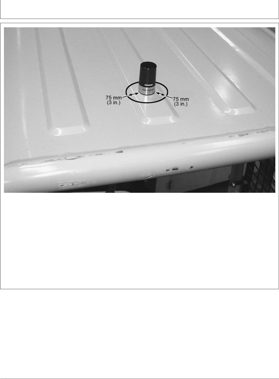
CED,TX13067,2598 –19–22NOV99–2/2
T128065B –UN–03FEB00
Cellular Antenna Ground Plane
At least 75 mm (3.0 in.) around the cellular antenna
in every direction must be free of other metal items
like hand holds, beacons or other antannas. The
area must be flat to ensure a good ground plane.
2. Mark the roof or panel so the holes will be at least
76 mm (3 in.) apart. (The GPS antenna mounting
hole location is OK).
3. Drill one hole 3/8 in. for the cellular antenna.
4. Drill the other hole 7/8 in. for the GPS antenna.
5. Assemble antennas through roof following
guidelines in Assembling Antennas Using Mounting
Bracket.
DeereTrax (03FEB00)
33
Installation Instruction
020300
PN=35
Installation Instruction
CED,TX13067,2460 –19–03AUG99–1/2
SYSTEM TESTING
To determine if unit is functioning properly, move machine
outdoors with no overhead obstructions or power lines.
1. Engine OFF.
2. Key ON.
3. Observe CELL and GPS LED lights as ignition key is
turned ON. Both LED lights must be ON for 1—5
seconds indicating power to the communications
controller. LED lights may go OFF indicating no cellular
service or GPS lock.
4. The system will now test CELL and GPS functionality.
Both LED lights will come ON indicating successful
completion of this test. This may take 10 minutes.
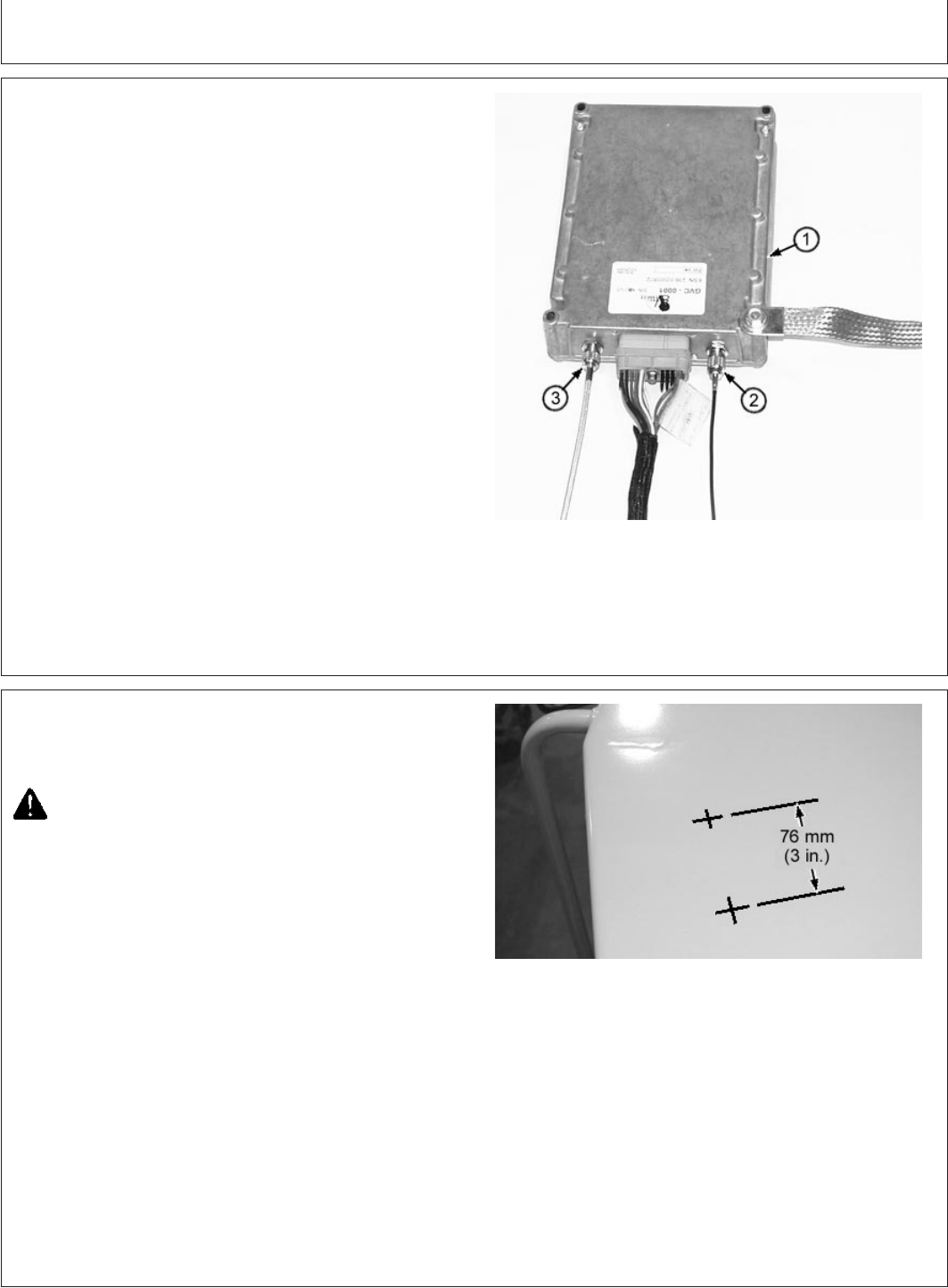
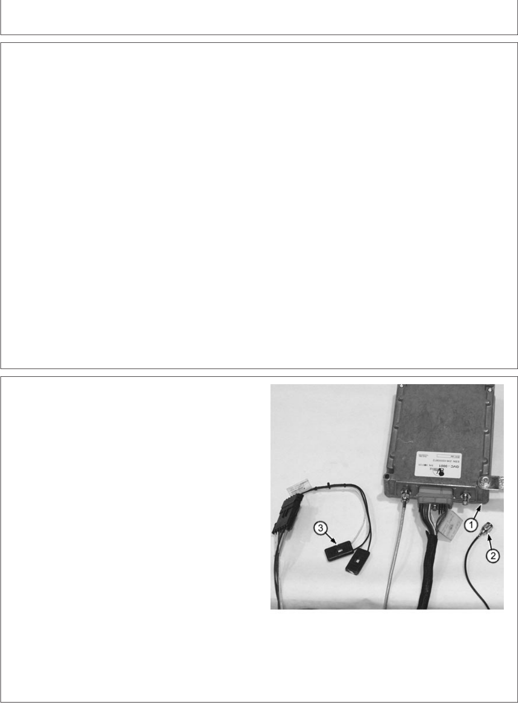
CED,TX13067,2460 –19–03AUG99–2/2
T127603B –UN–22JAN00
5. Carefully remove GPS antenna cable (2) from
communications controller (1). The GPS LED light (3)
should go OFF to indicate No GPS lock.
6. With GPS antenna cable disconnected, start engine.
LED light should come ON indicating the engine is
running.
7. Stop engine. Connect GPS antenna cable.
System is OK.
DeereTrax (03FEB00)
34
Installation Instruction
020300
PN=36
Installation Instruction
CED,TX13067,2595 –19–18NOV99–1/3
VEHICLE HOURS SYNCHRONIZATION
When installation is complete, vehicle hours must be
synchronized with communications controller.
Record vehicle hours, date and time of synchronization on
DeereTrax
Installation Record.
When DeereTraxInstallation Record is complete Fax it
to the number on the record.
To synchronize the communications controller:
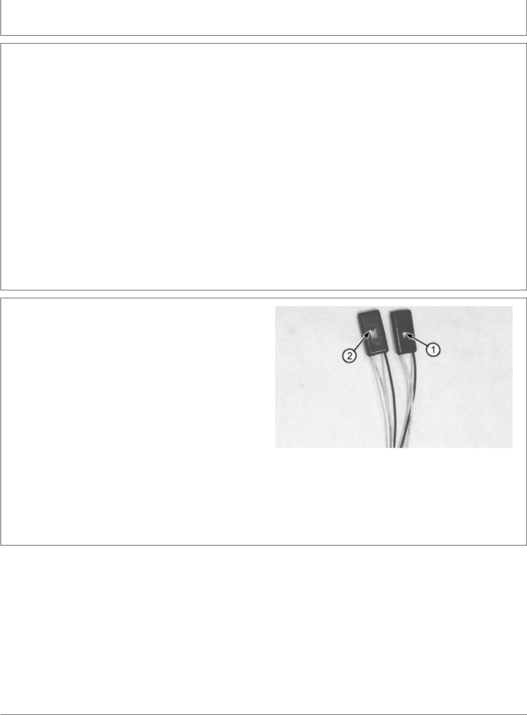
CED,TX13067,2595 –19–18NOV99–2/3
T125457B –UN–23NOV99
1—GPS Light
2—CELL Light
1. Key switch ON. Wait for both LED lights (1 and 2) to
come ON.
Continued on next page
DeereTrax (03FEB00)
35
Installation Instruction
020300
PN=37
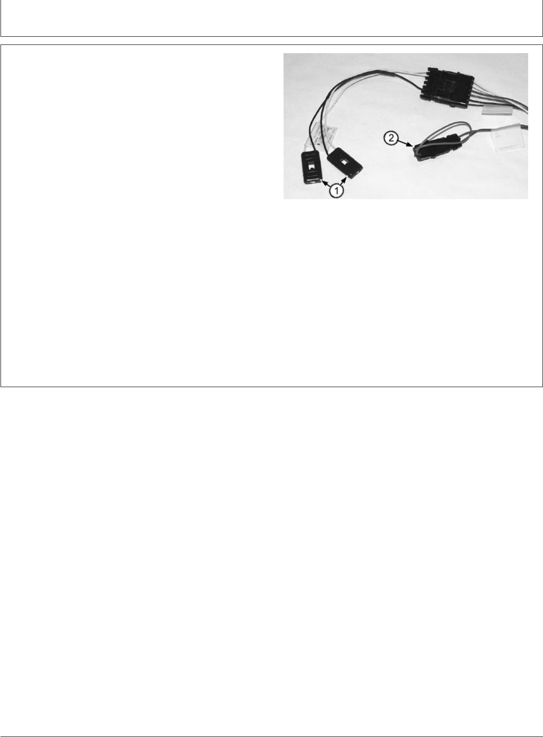
Installation Instruction
CED,TX13067,2595 –19–18NOV99–3/3
T128066B –UN–03FEB00
LED Lights and Diagnostic Connector
1—GPS and CELL Lights
2—Diagnostic Connector
2. Disconnect diagnostic connector (2), wait more than
six seconds.
3. Connect diagnostic connector.
4. Watch LED lights (GPS and CELL lights) (1).
5. GPS light goes OFF.
6. CELL light remains ON.
7. Cell light goes OFF.
8. When both lights come back ON, system is OK.
9. If both lights DO NOT come back ON, go to Problem
Diagnosis.
DeereTrax (03FEB00)
36
Installation Instruction
020300
PN=38

Installation Instruction
CED,TX13067,2532 –19–05OCT99–1/3
PROBLEM DIAGNOSIS
Symptom Problem Solution
LED Lights Do Not Come ON Blown fuses Check fuses in power harness
When Key Is Turned ON
Connection to alternator incorrect Check harness connections to
terminals on alternator.
B+ unswitched power (Red Wire)
must be connected to positive (+)
power source.
GND (Black wire) must be
connected to clean frame ground.
D+ switched power (Brown Wire)
must be connected to positive (+)
power source. Voltage with key ON.
Power harness failure Check Brown wire in four-pin power
harness connector. It must have
voltage only when the key is ON.
Check Red wire in four-pin power
harness connector. It must have
voltage all the time.
Check Black wire in four-pin power
harness connector. It must have a
good connection to frame ground.
Communications controller harness Check pin 1A (Red wire) in
failure connector to communications
controller. It must have battery
voltage at all times.
Check pin A3 (Brown wire) for
battery voltage only when key is ON.
Check pin 2A (Black wire) for
continuity to frame ground.
DeereTrax (03FEB00)
37
Installation Instruction
020300
PN=39
Continued on next page

Installation Instruction
CED,TX13067,2532 –19–05OCT99–2/3
Symptom Problem Solution
LED harness failure Check for battery voltage on both
Yellow wires in six-pin connector on
communications controller harness
as key is turned ON (Use the Black
wire in that connector as a ground
reference).
Voltage may fluctuate for five
seconds, but should remain constant
after that.
If voltage is present on yellow wires,
but LED lights aren’t ON, harness
has failed. replace harness.
Communications controller failure If voltages in previous checks are
correct, communications controller
has failed.
Cellular Connection LED Does Cellular antenna cable connection Check cellular cable connection at
Not Come ON antenna and communications
controller.
Cellular antenna failure Check general antenna condition.
Replace if damage is seen.
Lack of cellular service Assure cellular service is available,
call with a hand-held cellular phone
to be sure. Perform procedure to
activate cellular service. If service is
still not activated, call Customer
Support Center at 1-800-939-0805
Communications controller failure Replace antenna and cable. Verify
cellular phones will work in that
location. If LEDs do not come ON
and voltage checks are OK, replace
communications controller.
GPS LED Light Does Not Come Obstructed view of sky Move machine to an open location
ON (Engine OFF) away from buildings and overhead
power lines.
DeereTrax (03FEB00)
38
Installation Instruction
020300
PN=40
Continued on next page

Installation Instruction
CED,TX13067,2532 –19–05OCT99–3/3
Symptom Problem Solution
GPS antenna failure Check general antenna condition,
replace if damage is seen.
GPS antenna cable connection Check GPS antenna cable
connections at antenna and
communications controller.
Communications controller failure Replace antenna and cable. If LEDs
do not come ON and voltage checks
are OK, replace communications
controller.
GPS LED Light Does Not Come Blown fuse Check W+/R+ Engine Running Fuse
ON (Engine Running) in Power Harness
Incorrect voltage or poor connection With engine running a minimum of 6
at engine running signal source volts must be present at W+/R+
Engine Running connection to
engine (Purple wire).
Power harness failure With engine running, check for a
minimum of 6 volts on Purple wire in
4-pin connector of power harness.
Communications controller harness With engine running, check for a
failure minimum of 6 volts on pin B-1
(Purple wire) in connector of
communications controller harness.
Communications controller failure If voltages are correct,
communications controller has failed.
DeereTrax (03FEB00)
39
Installation Instruction
020300
PN=41

Installation Instruction
DeereTrax (03FEB00)
40
Installation Instruction
020300
PN=42