Deere and John Deere Intelligent Solutions Group VCA10001 User Manual 151919UNIT
Deere & Company dba John Deere Intelligent Solutio 151919UNIT
UserManual.wiki
>
Deere and John Deere Intelligent Solutions Group
>
VCA10001 User Manual
>
Revised Inst Manual
Contents
1.
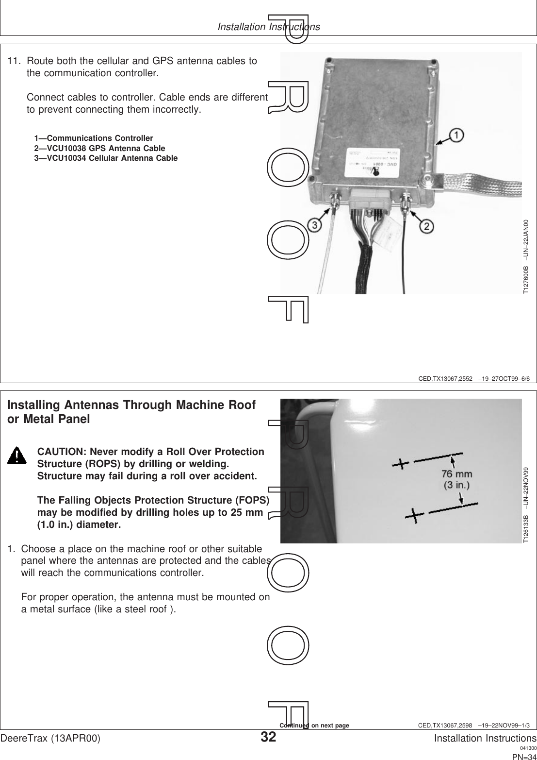
Instruction Manual
2.
Revised Inst Manual
Revised Inst Manual
Navigation menu
Upload a User Manual
Namespaces
Wiki Guide
HTML
PDF
Info
Views
User Manual
Discussion / Help
Navigation