Deister Electronic AMANTAGCOMPACT Compact Reader User Manual 2007 08 08 pa amantag compact em
Deister Electronic GmbH Compact Reader 2007 08 08 pa amantag compact em
user manual

compact
Wiring & Installation
Instructions
V04/09/07

© Copyright 2007 by deister electronic GmbH
All rights reserved. No part of this publication may be reproduced, stored in a retrieval
system, or transmitted, in any form or by any means, electronic, mechanical, photocopying,
recording, or otherwise, without prior written permission of deister electronic GmbH.
deister electronic GmbH reserves the right to make changes to any and all parts of this
documentation without obligation to notify any person or entity of such changes.
September 2007 FS/BF
deister electronic GmbH
Hermann-Bahlsen Str. 11
30890 Barsinghausen
Germany
Phone: +49 (0) 51 05 - 51 61 11
Fax: +49 (0) 51 05 - 51 62 17
E-Mail: info@deister-gmbh.de
Web: www.deister.com
2deister electronic GmbH 30890 Barsinghausen Germany V04/09/07
amanTag compact

Content
1. General Information...................................................4
2. Technical Data.............................................................5
3. Operation....................................................................5
4. Wiring & Configuration ..............................................6
4.1 Optical display ..................................................................................................6
4.2 Pin assignment....................................................................................................7
4.3 DIP-switches.......................................................................................................9
5. Installation................................................................12
5.1 General Information..........................................................................................12
5.2 Mounting.........................................................................................................12
6. Regulatory notices.....................................................14
V04/09/07 deister electronic GmbH 30890 Barsinghausen Germany 3
amanTag compact

1. General Information
●An amanTag compact-Reader generates an undirected field in an area up to 3 meters.
In a vertical line to the reader the reading range is up to 8 meters.
●An amanTag compact-Reader is able to recognize several transponders being in the
reader-field at the same time.
●The reading range can be varied gradually.
●For exchange of data a Wiegand or RS 485 Interface can be used.
4deister electronic GmbH 30890 Barsinghausen Germany V04/09/07
amanTag compact

2. Technical Data
Meets EN(I-ETS) 300220
Dimensions (mm): 296 x 296 x 28
Transmission frequency: 8,1 kHz
Receiving frequency: 433 MHz ISM-band
Modulation: PSK
Baud-rate in reading: 1500 Baud
Sensibility: -100dBm
Reading distance: up to 8 m, depending on the type of transponder
Field strength in 8m distance: 99 dBμV/m average , 102 dBμV/m peak
Interface: Wiegand, RS485
Voltage supply: 24V (18V...30V)
3. Operation
Two different frequency ranges are used to communicate with the transponder. The
activating of a transponder and data exchange to the transponder takes place within a low
frequent 8,1 kHz-field. Data exchange from the transponder to the reader takes place at
433 MHz.
As soon as a transponder is brought into the working range of the low frequent field, it will
be activated and recognized by the reader.
The transponder stays in direct contact with the reader as long as it is located in the
working range of the low frequent field.
V04/09/07 deister electronic GmbH 30890 Barsinghausen Germany 5
amanTag compact
4. Wiring & Configuration
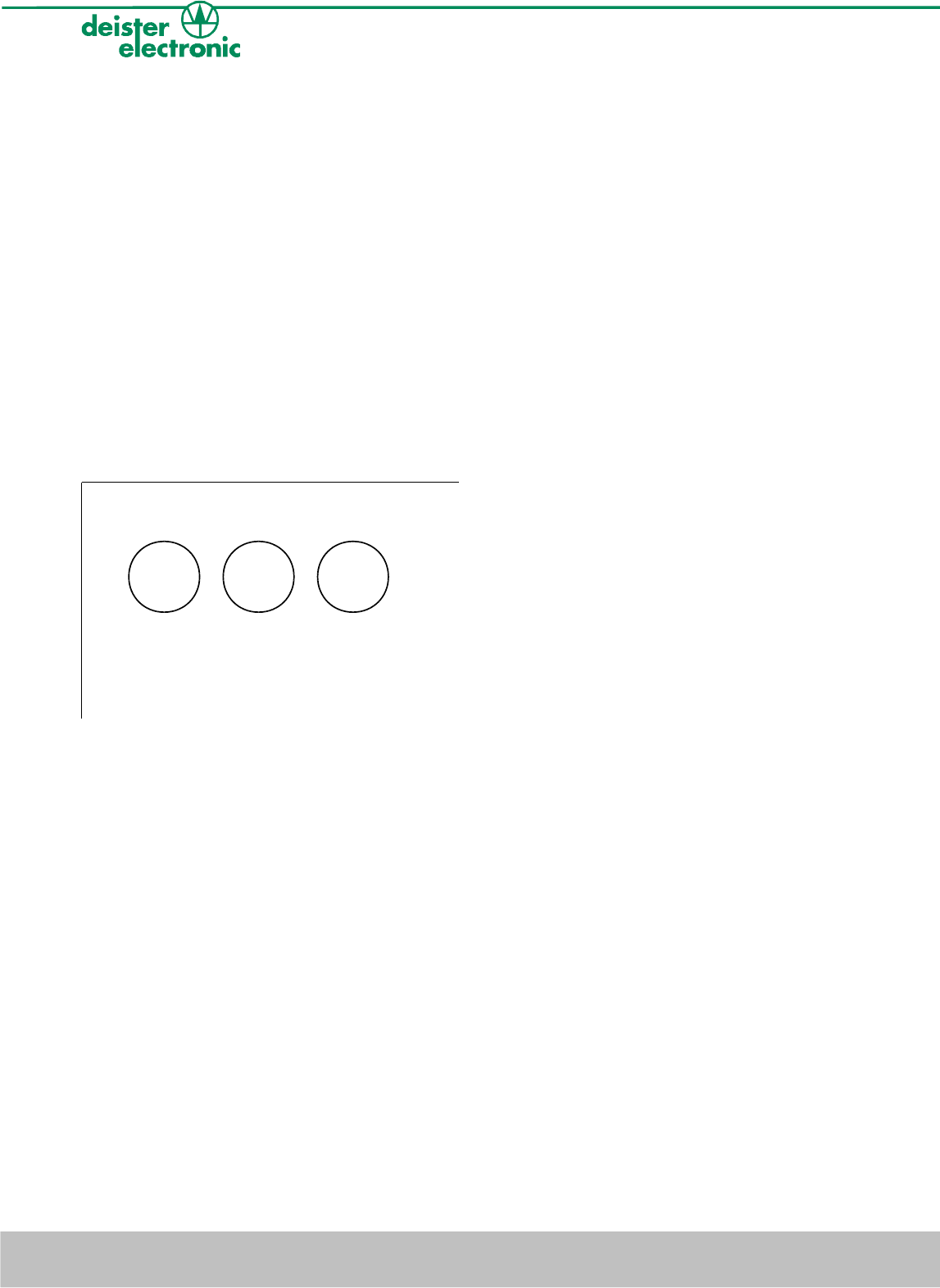
4.1 Optical display
An amanTag compact is equipped with three LEDs for optical display. The functions
assigned are as follows:
LED yellow: “Power ON”-display.
Turned on const antly when connected to the power supply.
LED green: Tag received.
Blinks in case a transponder telegram has been received.
LED red: Tag i n fie ld.
Is active as long as a transponder is located in the field.
6deister electronic GmbH 30890 Barsinghausen Germany V04/09/07
amanTag compact
yellow green red
Board of the reader
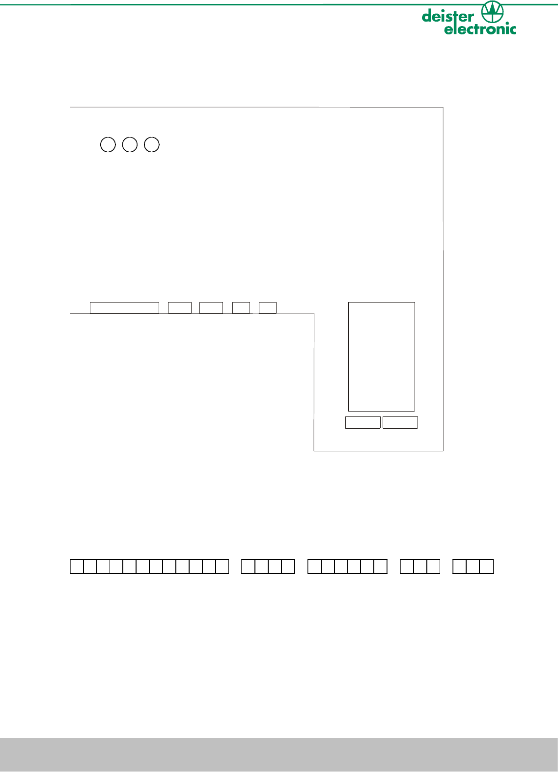
4.2 Pin assignment
A schematic description of the position of the pins and dip-switches is given in the diagram below:
ST2
ST1
ST3
ST4 ST5
DIP-Switches
Bank A Bank B
yellow
green
red
In the lower part of the card there are five connector rails for connecting to the power
supply and to other devices in the peripheral equipment. The connector rails are assigned
as follows.
V04/09/07 deister electronic GmbH 30890 Barsinghausen Germany 7
amanTag compact
ST1 ST2 ST3 ST4 ST5
123456789101112 1224 123456 123 123

ST1 (PRX)
P1 beeper–input
P2 ground
P3 positive currant voltage 24V (18V – 30V)
P4 Wiegand-output D1 ( loading arrangement RS 232 )
P5 Wiegand-output D0
P6 Wiegand-output CP
P7 LED green input
P8 LED red input
P9 RS485 - A
P10 RS485 - B
P11 Tamper-contact
P12 Tamper-contact
ST2 (SATELLITE)
P1 positive currant voltage, 24V (18V ... 30V)
P2 ground
P3 RS485 - A
P4 RS485 – B
ST3 (SYNC)
P1 positive currant voltage, 24V (18V ... 30V)
P2 ground
P3 SYNC - A
P4 SYNC – B
P5 SYNC-AIN
P6 SYNC-BIN
ST4 (RELAYS 1)
P1 connected to P2, in case yellow LED is turned off (Breakdown of
current voltage or alarm-condition)
P2 reference connection of the relays
P3 connected to P2, in case the yellow LED is turned on
ST5 (RELAYS 2)
P1 connected to P2, in case the red LED is turned off
P2 reference connection of the relays
P3 connected to P2, in case the red LED is turned on (alarm-condition)
8deister electronic GmbH 30890 Barsinghausen Germany V04/09/07
amanTag compact

4.3 DIP-switches
The amanTag compact can be configured with two eight pole dip-switches (rail A and B).
A1 activate the monitor tag function.
A2 always has to be „on“.
A3 reserved for testing-modes, has to be turned off!
A4 in case this switch is set, the RS485-address is defined by the door-number
A5-A8 Binary switch-group for definition of the door number
The numbers 0000 and 1000 must not be used!
B1-B4 binary switch-group to determine the wake-up-range
B5 reserved for testing-modes, has to be turned off!
B6 special function for ending the transport mode of the transponders. Should be
turned off during normal working mode.
B7 reserved for testing-modes, has to be turned off!
B8 has to be set, to activate the RS485-receiver.
V04/09/07 deister electronic GmbH 30890 Barsinghausen Germany 9
amanTag compact
ON ON
#
#
#####
#
#
##
#####
A1 A2 A3 A4 A5 A6 A7 A8 B1 B2 B3 B4 B5 B6 B7 B8
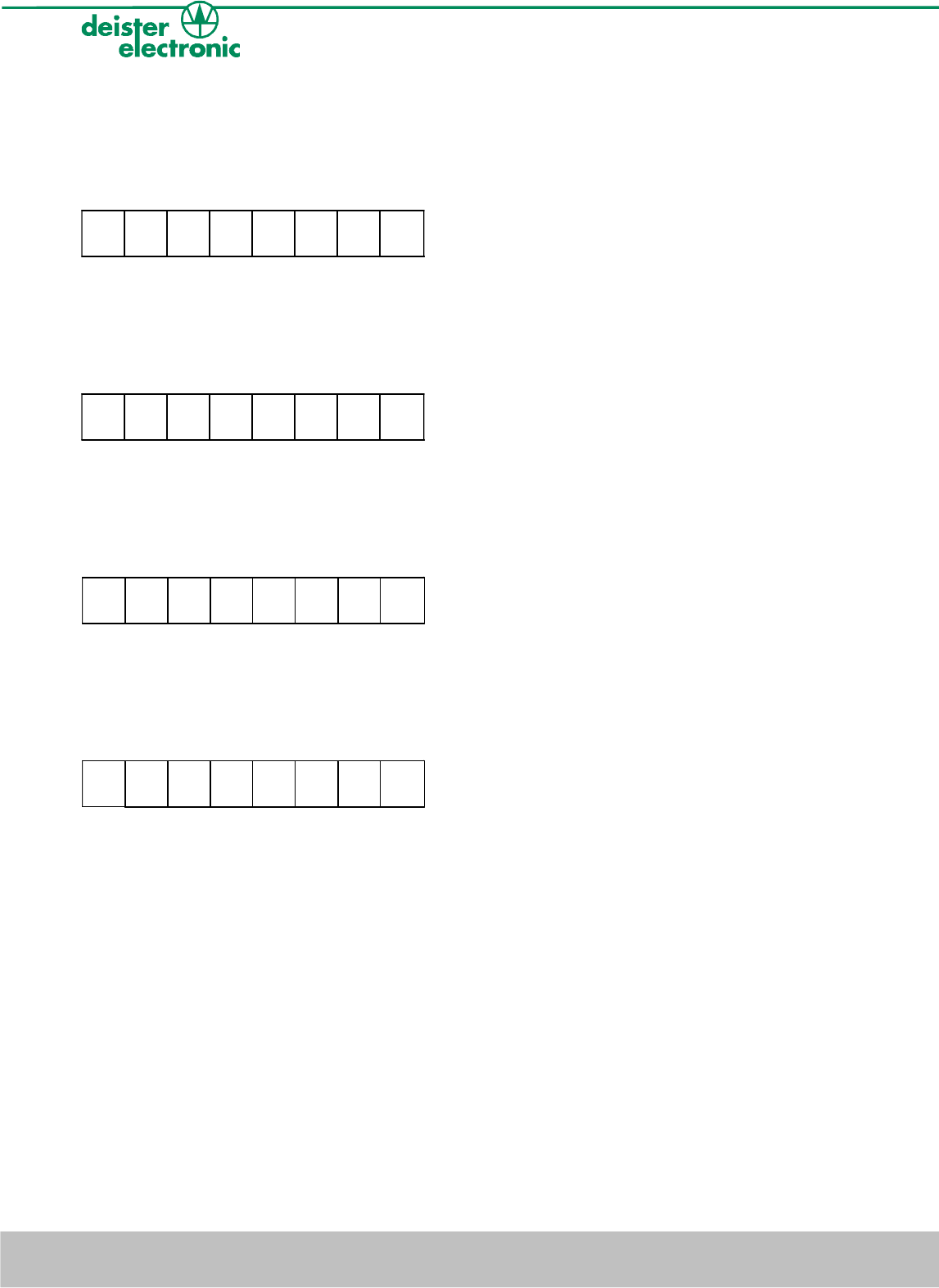
Examples for adjusting the door-number:
Door-number 1:
Door-number 2:
Door-number 3:
Door-number 8: (reserved, should not be used)
10 deister electronic GmbH 30890 Barsinghausen Germany V04/09/07
amanTag compact
ON
######
# #
A1 A2 A3 A4 A5 A6 A7 A8
ON
########
A1 A2 A3 A4 A5 A6 A7 A8
ON
######
# #
A1 A2 A3 A4 A5 A6 A7 A8
ON
######
# #
A1 A2 A3 A4 A5 A6 A7 A8
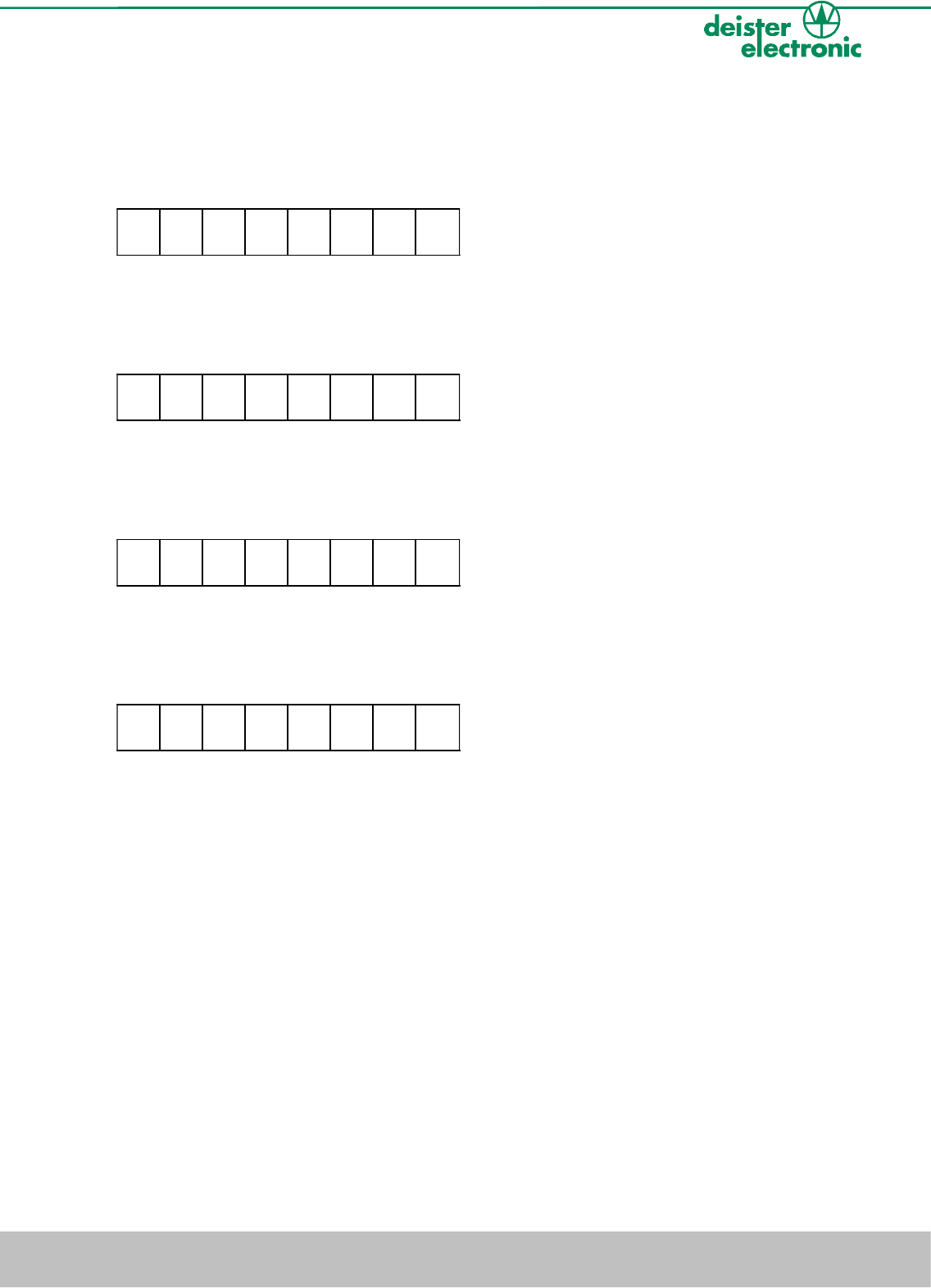
Examples for adjusting the wake-up-range:
Range 1:
Range 2:
Range 3:
Range 8:
V04/09/07 deister electronic GmbH 30890 Barsinghausen Germany 11
amanTag compact
ON
########
B1 B2 B3 B4 B5 B6 B7 B8
ON
########
B1 B2 B3 B4 B5 B6 B7 B8
ON
########
B1 B2 B3 B4 B5 B6 B7 B8
ON
########
B1 B2 B3 B4 B5 B6 B7 B8
5. Installation
5.1 General Information
●During the installation it is important to take care that the readers are not too close
together. The low frequent fields of the readers must not overlap.
●The wake-up-fields of the different readers must not overlap. The range of the field can
be varied by the dip-switches B1-B4.
●Mounting on a metallic surface or on brick-walls with lots of steel reinforcement can
reduce (or unexpectedly extend) the wake-up-range of the reader.
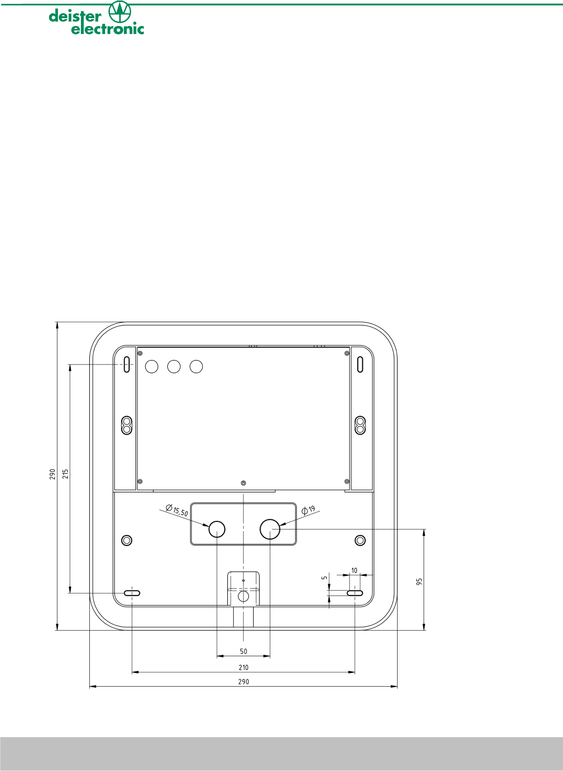
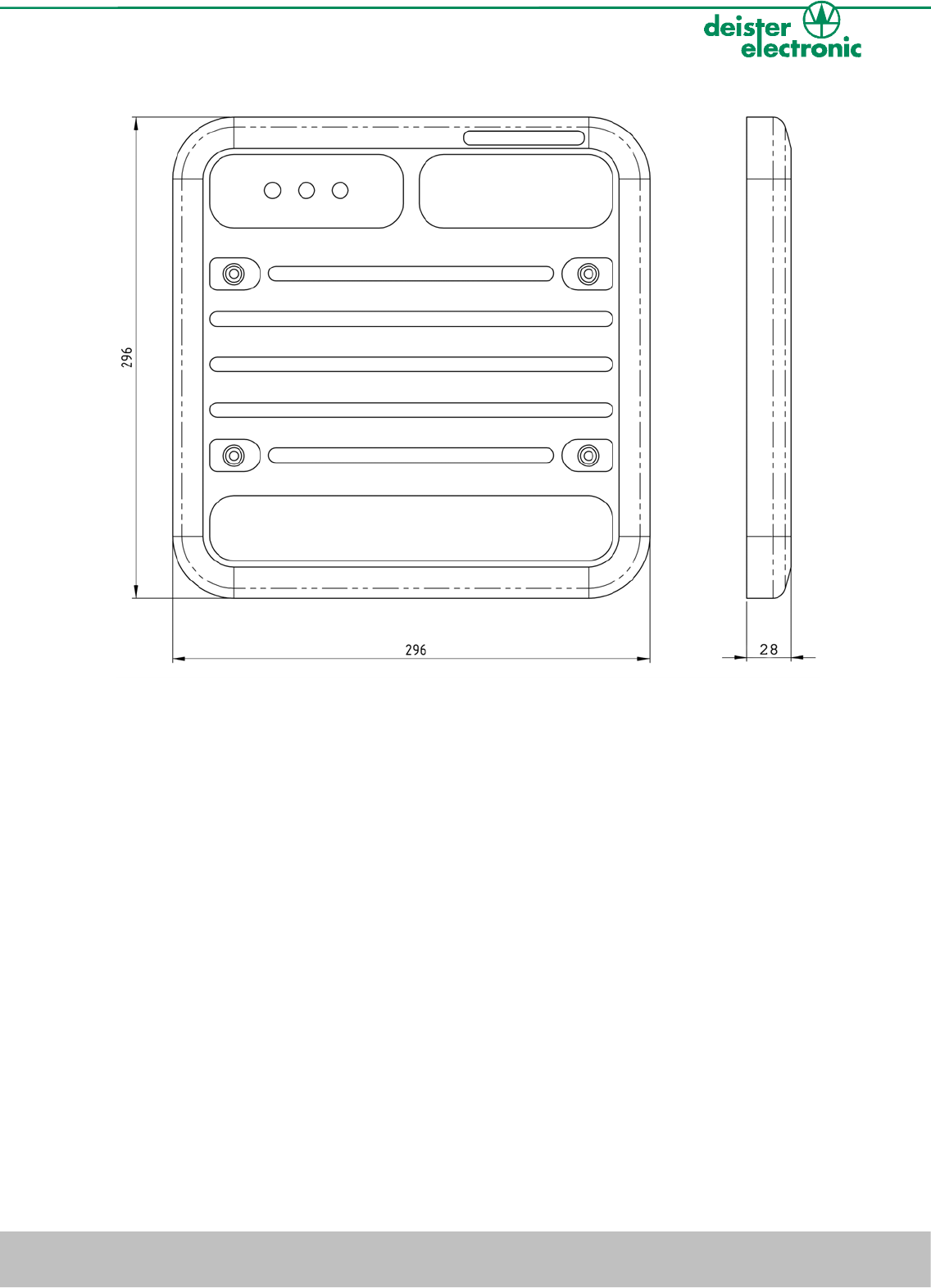
5.2 Mounting
The amanTag compact reader will be mounted to the wall with 4 screws. The back panel
of the device is provided with the according drill holes for the screws and the wire outlets.
The dimensions can be seen in the following diagrams.
12 deister electronic GmbH 30890 Barsinghausen Germany V04/09/07
amanTag compact
V04/09/07 deister electronic GmbH 30890 Barsinghausen Germany 13
amanTag compact

6. Regulatory notices
Hereby, deister electronic GmbH declares that this equipment - if used according to the
instructions - is in compliance with the essential requirements and other relevant provisions
of the RTTE Directive 1999/5/ EC.
A full declaration of conformity can be requested at:
info@deister-gmbh.de
Approved for use in all European countries.
FCC Digital Device Limitations
Radio and Television Interference
This equipment has been tested and found to comply with the limits for a Class A digital
device, pursuant to part 15 of the FCC Rules. These limits are designed to provide
reasonable protection against harmful interference when the equipment is operated in a
commercial environment. This equipment generates, uses, and can radiate radio
frequency energy and, if not installed and used in accordance with the instruction manual,
may cause harmful interference to radio communications. Operation of this equipment in
a residential area is likely to cause harmful interference in which case the user will be
required to correct the interference at his own expense.
CAUTION: Changes or modifications not expressly approved by the manufacturer could
void the user’s authority to operate this equipment.
Industry Canada
This Class A digital apparatus complies with Canadian ICES-003.
Cet appareil numérique de la classe A est conforme à la norme NMB-003 du Canada.
This device complies with Industry Canada licence-exempt RSS standard(s).
Operation is subject to the following two conditions:
(1) this device may not cause interference, and (2) this device must accept any interference,
including interference that may cause undesired operation of the device. Le présent appareil est
conforme aux CNR d'Industrie Canada applicables aux appareils radio exempts de licence.
L'exploitation est autorisée aux deux conditions suivantes : (1) l'appareil ne doit pas produire de
brouillage, et (2) l'utilisateur de l'appareil doit accepter tout brouillage radioélectrique subi,
même si le brouillage est susceptible d'en compromettre le fonctionnement.
14 deister electronic GmbH 30890 Barsinghausen Germany V04/09/07
amanTag compact

Notes:
V04/09/07 deister electronic GmbH 30890 Barsinghausen Germany 15
amanTag compact

Germany:
deister electronic GmbH
Hermann-Bahlsen Str. 11
30890 Barsinghausen
Tel.: +49 (0) 51 05 - 51 61 11
Fax: +49 (0) 51 05 - 51 62 17
info@deister-gmbh.de
www.deister.com
deister worldwide
France:
deister electronic france
101 rue Pierre Semard
92320 Chatillon
Tel.: +33 (0) 1 47 - 35 78 78
Fax: +33 (0) 1 47 - 35 92 59
info.fr@deister.com
Great Britain:
deister electronic (UK) Ltd.
Stapleton Way, Enterprise Park
Spalding, Lincolnshire
PE11 3YQ
Tel.: +44 (0) 1775 - 717100
Fax: +44 (0) 1775 - 717101
info.uk@deister.com
Japan:
deister electronic Japan, LTD.
Toshiba Hoshikawa Bldg. 4F
2-4 Kawabe-chô
Hodogaya-ku, Yokohama-shi
Kanagawa, 240-0001
Tel.: +81 (0) 45 340 1831
Fax: +81 (0) 45 340 1801
info.jp@deister.com
Americas and Caribbean:
Deister Electronics USA, Inc.
9303 Grant Avenue
Manassas, VA 20110
Tel.: +1 703 - 368 2739
Fax: +1 703 - 368 9791
info.us@deister.com