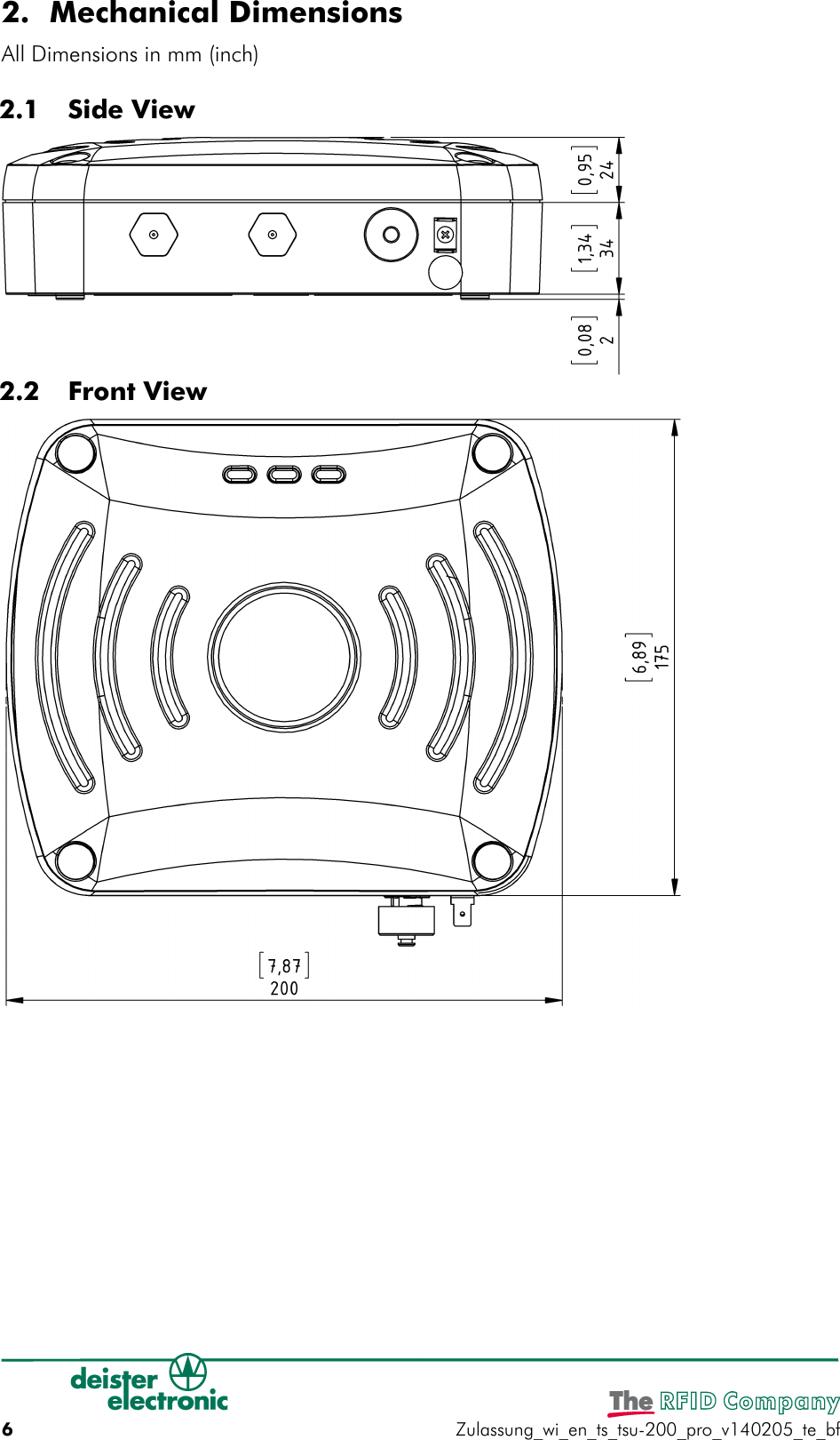
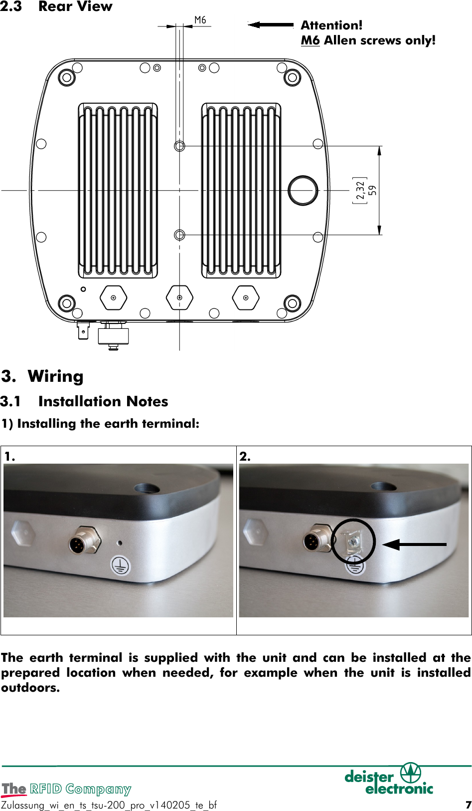
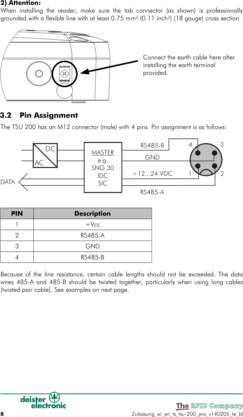
Deister Electronic TSU200 RFID Reader User Manual
Deister Electronic GmbH RFID Reader
UserManual.wiki
>
Deister Electronic
>
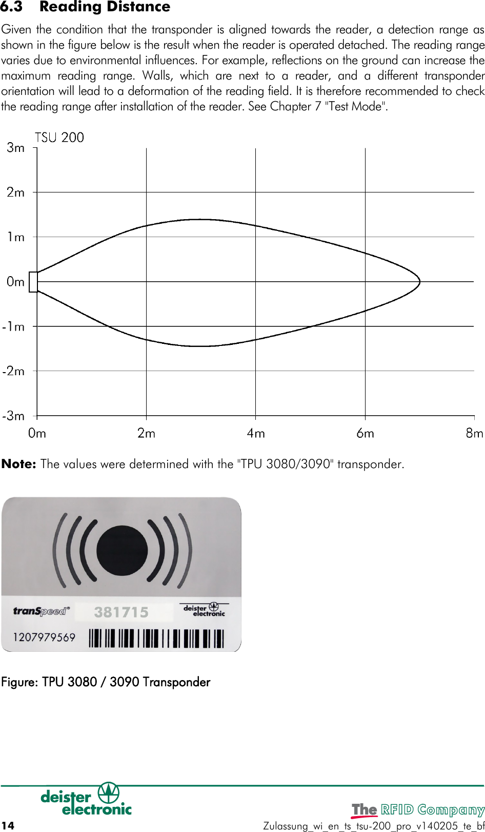
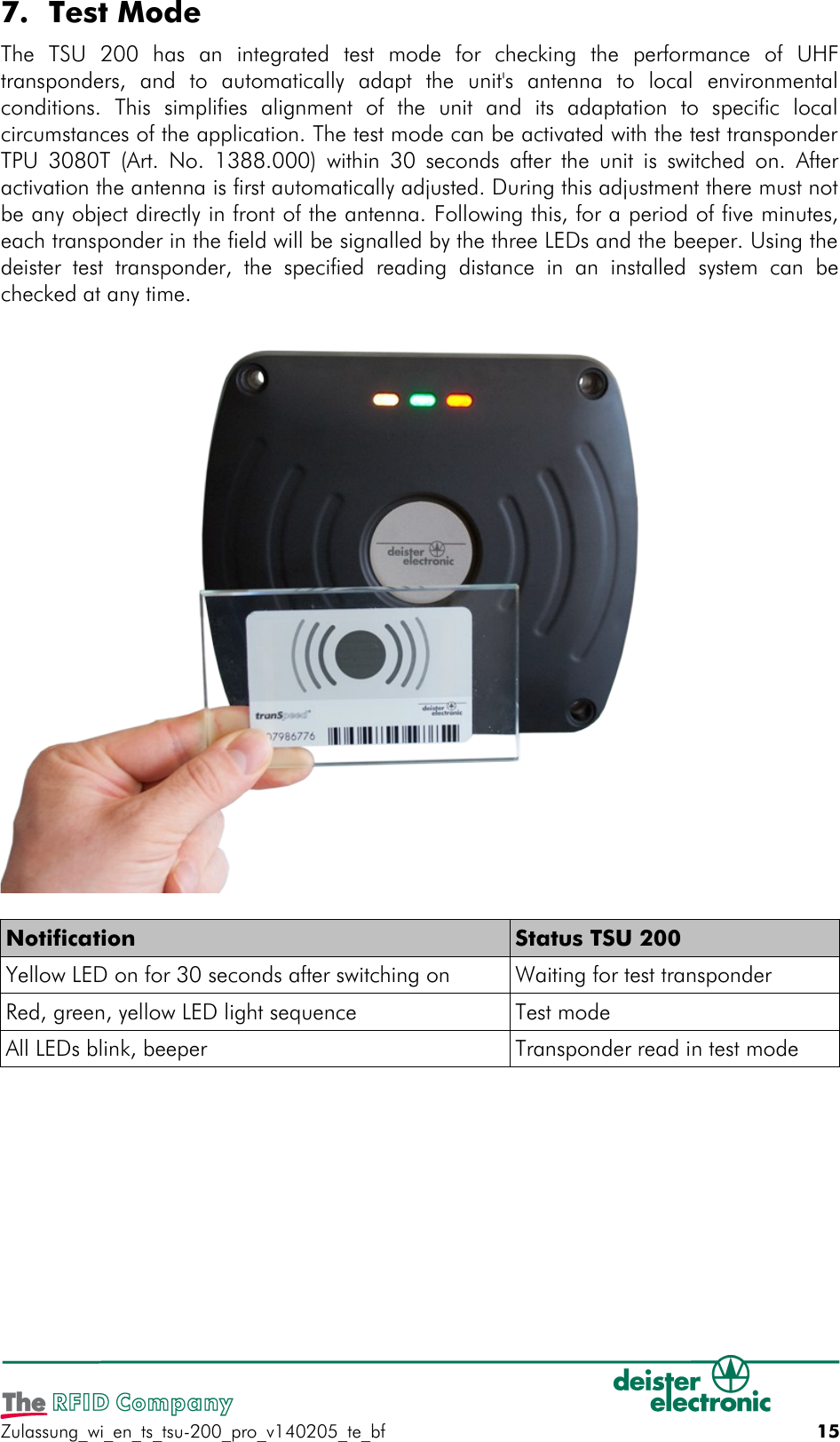
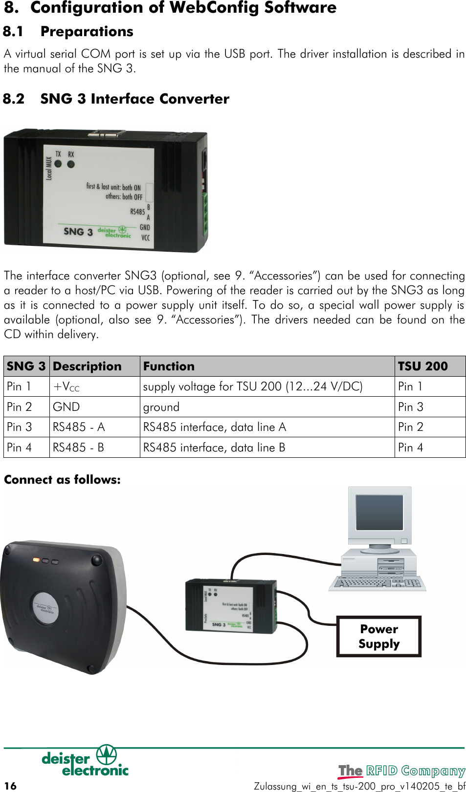
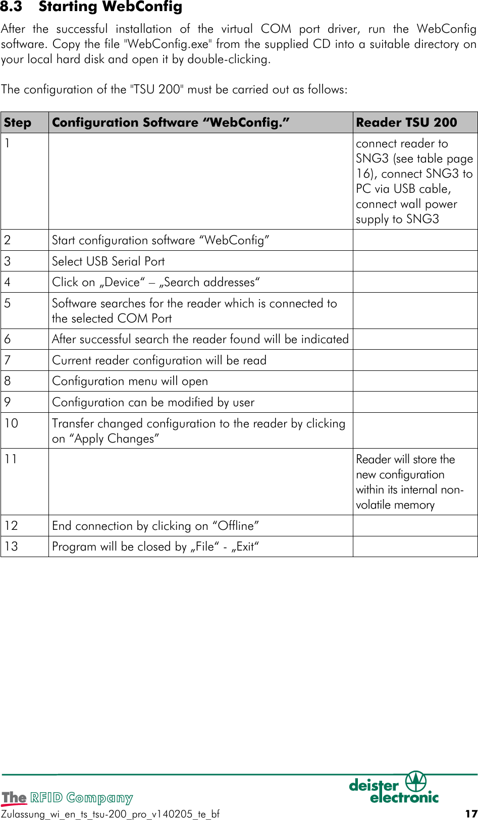
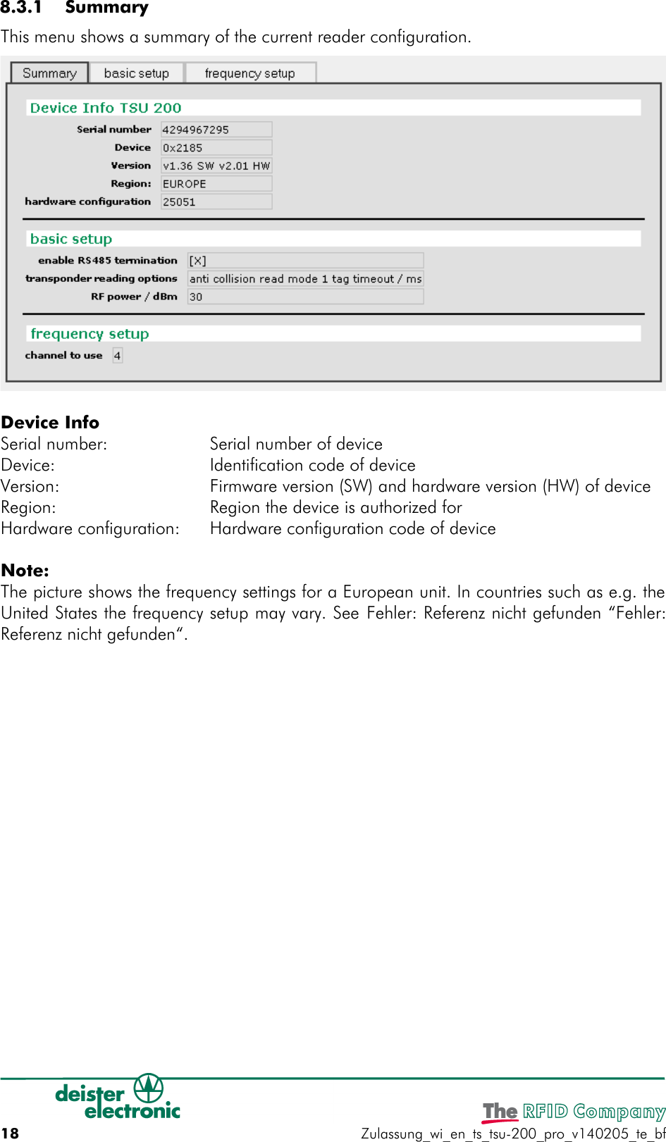
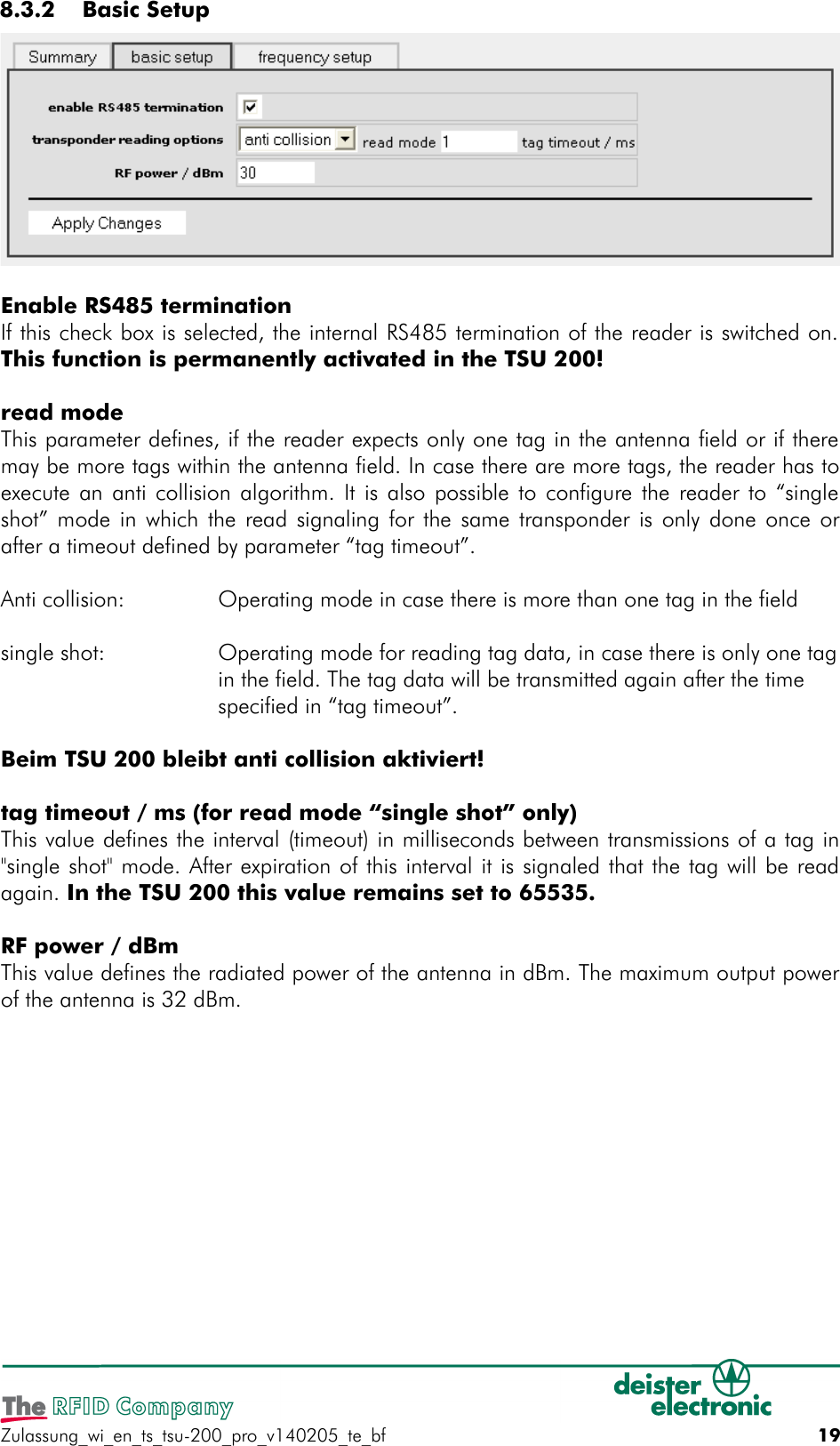
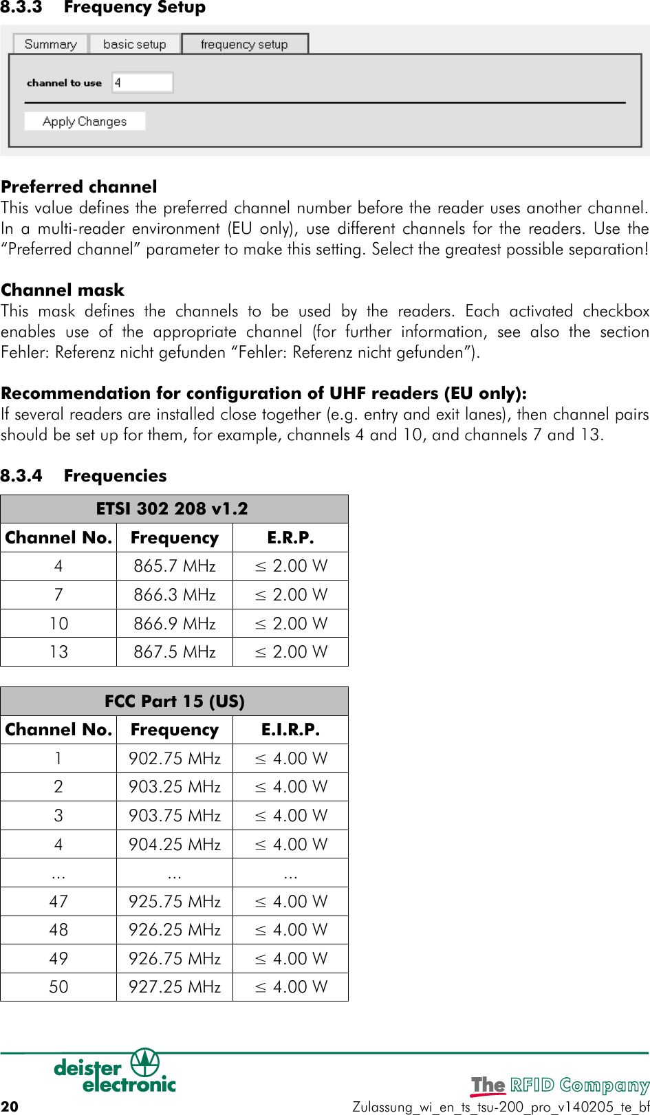
TSU200 User Manual
user manual
Navigation menu
Upload a User Manual
Namespaces
Wiki Guide
HTML
PDF
Info
Views
User Manual
Discussion / Help
Navigation