Deister Electronic TSU200 RFID Reader User Manual
Deister Electronic GmbH RFID Reader
user manual

Art. # 896215 Zulassung_wi_en_ts_tsu-200_pro_v140205_te_bf
TSU 200
Long Distance Reader
Wiring and Installation
Instructions

Regulatory Notices
Europe
Hereby, deister electronic GmbH declares that this equipment - if used according to the in-
structions - is in compliance with the essential requirements and other relevant provisions
of the RTTE Directive 1999/5/EC.
A full declaration of conformity can be requested at:
info@deister-gmbh.de
Approved for use in all European countries.
FCC Digital Device Limitations
Radio and Television Interference
This equipment has been tested and found to comply with the limits for a Class A digital
device, pursuant to Part 15 of the FCC rules. These limits are designed to provide reason-
able protection against harmful interference when the equipment is operated in a commer-
cial environment. This equipment generates, uses and can radiate radio frequency energy
and, if not installed and used in accordance with the instruction manual, may cause harm-
ful interference to radio communications. Operation of this equipment in a residential area
is likely to cause harmful interference, in which case the user will be required to correct the
interference at his own expense. This device complies with Part 15 of the FCC rules. Opera-
tion is subject to the following two conditions: (1) This device may not cause harmful interfer-
ence, and (2) this device must accept any interference received, including interference that may
cause undesired operation. In order to maintain compliance with FCC regulations, shielded
cables must be used with this equipment. Operation with non-approved equipment or un-
shielded cables is likely to result in interference to radio and television reception.
Caution! Changes or modifications not expressly approved by the manufacturer could void
the user´s authority to operate this equipment.
FCC Notice
To comply with FCC Part 15 rules in the United States, the system must be professionally
installed to ensure compliance with the Part 15 certification. It is the responsibility of the
operator and professional installer to ensure that only certified systems are deployed in the
United States. The use of the system in any other combination (such as co-located anten-
nas transmitting the same information) is expressly forbidden.
FCC Radiation Exposure Statement
This equipment complies with the FCC radiation exposure limits set forth for an uncon-
trolled environment. This equipment should be installed and operated with minimum dis-
tance of 20 cm between the radiator and the human body.
2Zulassung_wi_en_ts_tsu-200_pro_v140205_te_bf

Industry Canada
This device complies with Industry Canada licence-exempt RSS standard(s). Operation is
subject to the following two conditions:
(1) this device may not cause interference, and
(2) this device must accept any interference, including interference that may cause unde-
sired operation of the device.
Le présent appareil est conforme aux CNR d'Industrie Canada applicables aux appareils
radio exempts de licence. L'exploitation est autorisée aux deux conditions suivantes : (1)
l'appareil ne doit pas produire de brouillage, et (2) l'utilisateur de l'appareil doit accepter
tout brouillage radioélectrique subi, même si le brouillage est susceptible d'en compromet-
tre le fonctionnement.
© Copyright 2014 by deister electronic GmbH
Disclaimer
deister electronic GmbH is not able to supervise the observance of the instructions given in
this manual as well as the conditions and methods used during installation, operation and
maintenance of the electronic devices and components respectively. Therefore we disclaim
liability and reject responsibility for any losses, damages or costs that are caused by misap-
plication, installation, handling errors or faulty operation or related to the above in any
other way. All our products are subject to current advancement, therefore we reserve the
right for modifications without prior notice.
All rights reserved. No part of this publication may be reproduced, stored in a retrieval sys-
tem, or transmitted, in any form or by any means, electronic, mechanical, photocopying,
recording, or otherwise, without prior written permission of deister electronic GmbH.
deister electronic GmbH reserves the right to make changes to any and all parts of this
documentation without obligation to notify any person or entity of such changes.
deister electronic GmbH
Hermann-Bahlsen Str. 11
30890 Barsinghausen
Germany
Phone:+49 (0) 51 05 - 51 61 11
Fax: +49 (0) 51 05 - 51 62 17
E-Mail: info.de@deister.com
Web: www.deister.com
Zulassung_wi_en_ts_tsu-200_pro_v140205_te_bf 3

Content
1. Technical Data............................................................5
2. Mechanical Dimensions..............................................6
2.1 Side View...........................................................................................................6
2.2 Front View..........................................................................................................6
2.3 Rear View...........................................................................................................7
3. Wiring.........................................................................7
3.1 Installation Notes................................................................................................7
3.2 Pin Assignment...................................................................................................8
4. LEDs and Beeper.........................................................9
5. Mounting...................................................................10
5.1 Mounting on poles and pipes.............................................................................10
5.1.1 Mounting the base plate for mast mounting LRM3.......................................10
5.2 Montage on walls and ceilings...........................................................................11
5.2.1 Mounting with ball joint bracket LRM1........................................................11
5.2.2 Direct Mounting.......................................................................................11
5.3 Function Principle and Environmental Influences...................................................12
6. Installation Notes......................................................13
6.1 Installation on the side of the road:.....................................................................13
6.2 Installation above the road.................................................................................13
6.3 Reading Distance .............................................................................................14
7. Test Mode..................................................................15
8. Configuration of WebConfig Software .....................16
8.1 Preparations.....................................................................................................16
8.2 SNG 3 Interface Converter.................................................................................16
8.3 Starting WebConfig...........................................................................................17
8.3.1 Summary ................................................................................................18
8.3.2 Basic Setup..............................................................................................19
8.3.3 Frequency Setup......................................................................................20
8.3.4 Frequencies.............................................................................................20
9. Accessories................................................................23
4Zulassung_wi_en_ts_tsu-200_pro_v140205_te_bf

1. Technical Data
Dimensions:
mm (inch) W x H x D 200 x 175 x 60 (7.87 x 6.89 x 2.36)
Weight
kg (lbs) 1.2 (2.6)
Housing Material: ABS/PC, Al (powder-coated)
Protection Class: IP67
Operating Temperature:
°C (°F) -20 ... 50 (-4 ... 122)
Relative Humidity:
% 5...95, non-condensing
Power Requierement: 12...28 +20 % VDC / max. 1 A
Frequencies:
MHz 865 – 868 (EU)
902 – 928 (US)
Transmit Power:
E.R.P. max. 1 W (configurable)
Antennas with
Beam width/Polarization: 90° circular
Transponder Protocols: ISO18000-6 C (EPC Class1 Gen2)
Reading Distance:
m (ft.) up to 7 (23)
Writing Distance:
m (ft.) up to 50% of reading distance, depending on transponder,
antenna configuration and environmental conditions
Interface: RS485 (deBus Protokoll)
Electrical Connection: M12-Connector with 4 Pins
Conformity: EN 50346
EN 301489
Air Interface (EU) EN 302208 (DRM)
Zulassung_wi_en_ts_tsu-200_pro_v140205_te_bf 5
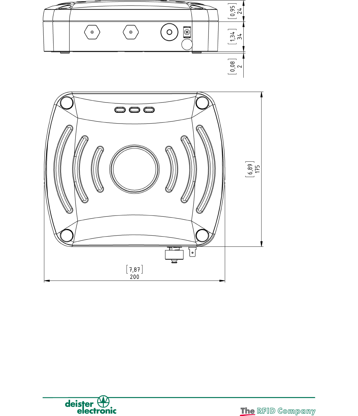
2. Mechanical Dimensions
All Dimensions in mm (inch)
2.1 Side View
2.2 Front View
6Zulassung_wi_en_ts_tsu-200_pro_v140205_te_bf
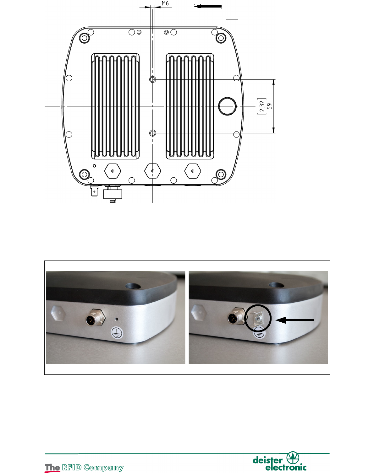
2.3 Rear View
3. Wiring
3.1 Installation Notes
1) Installing the earth terminal:
1. 2.
The earth terminal is supplied with the unit and can be installed at the
prepared location when needed, for example when the unit is installed
outdoors.
Zulassung_wi_en_ts_tsu-200_pro_v140205_te_bf 7
Attention!
M6 Allen screws only!
2) Attention:
When installing the reader, make sure the tab connector (as shown) is professionally
grounded with a flexible line with at least 0.75 mm² (0.11 inch²) (18 gauge) cross section.
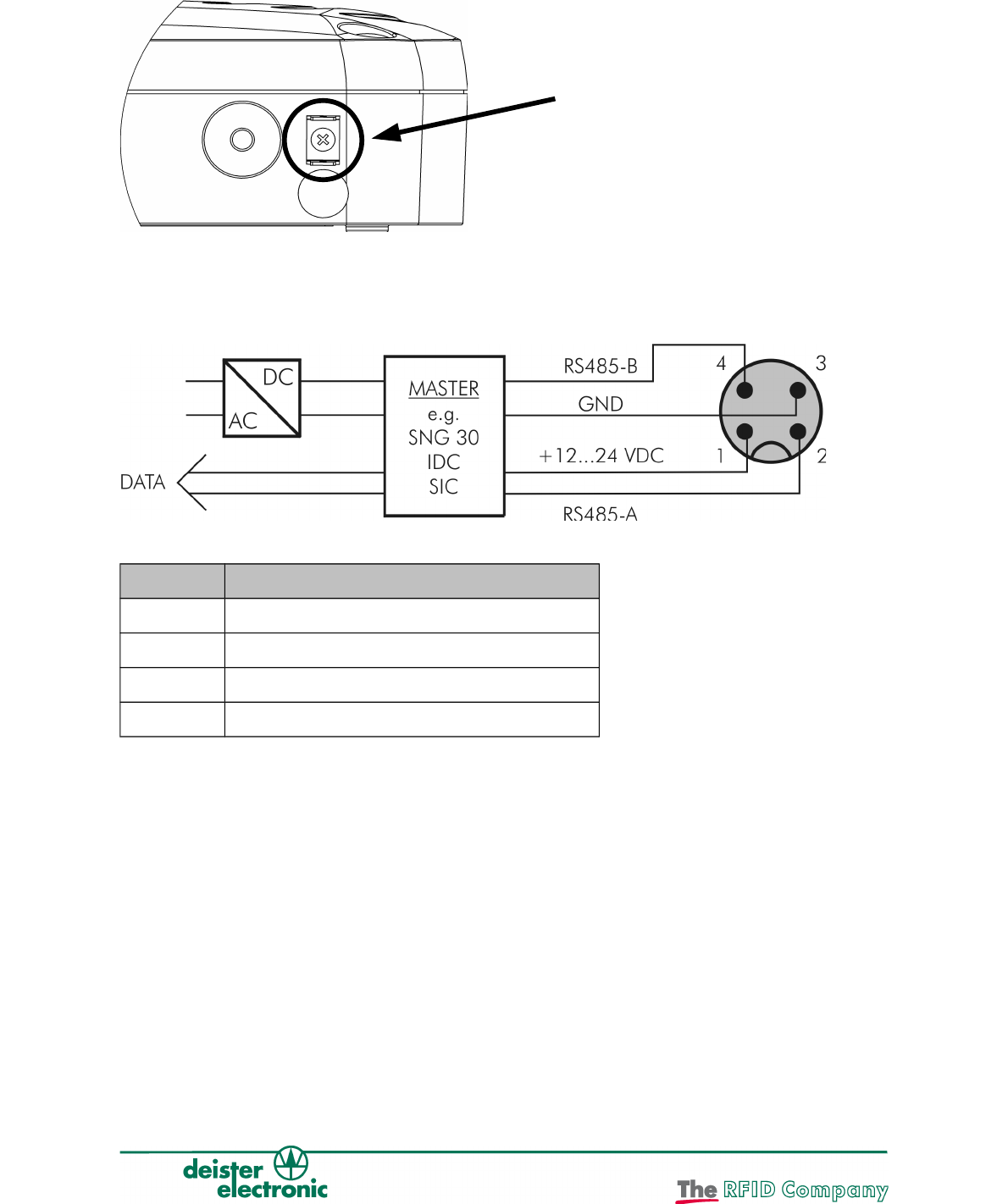
3.2 Pin Assignment
The TSU 200 has an M12 connector (male) with 4 pins. Pin assignment is as follows:
PIN Description
1 +Vcc
2 RS485-A
3 GND
4 RS485-B
Because of the line resistance, certain cable lengths should not be exceeded. The data
wires 485-A and 485-B should be twisted together, particularly when using long cables
(twisted pair cable). See examples on next page.
8Zulassung_wi_en_ts_tsu-200_pro_v140205_te_bf
Connect the earth cable here after
installing the earth terminal
provided.
Examples:
Power Supply Voltage Wire Diameter Maximum Cable Length
12V AWG24 (0,22mm²) 5 m (16.4 ft.)
24V AWG24 (0,22mm²) 50 m (164 ft.)
12V AWG20 (0,5mm²) 10 m (32.8 ft)
24V AWG20 (0,5mm²) 100 m (328 ft.)
4. LEDs and Beeper
The standard settings for the LEDs and the beeper are as follows:
LED/beeper Action Visualisation Status of TSU 200
Yellow LED Short blinks
(3 s off, 100 ms on)
Field switched off
Blinks (300 ms off, 500 ms on) Reader not interrogated
Constant on Field switched on
Off for short periods(200 ms off) Tag read
Green LED User-defined User-defined
Red LED User-defined Malfunction / user-defined
Beeper User-defined User-defined
= LED off / = LED on
Zulassung_wi_en_ts_tsu-200_pro_v140205_te_bf 9
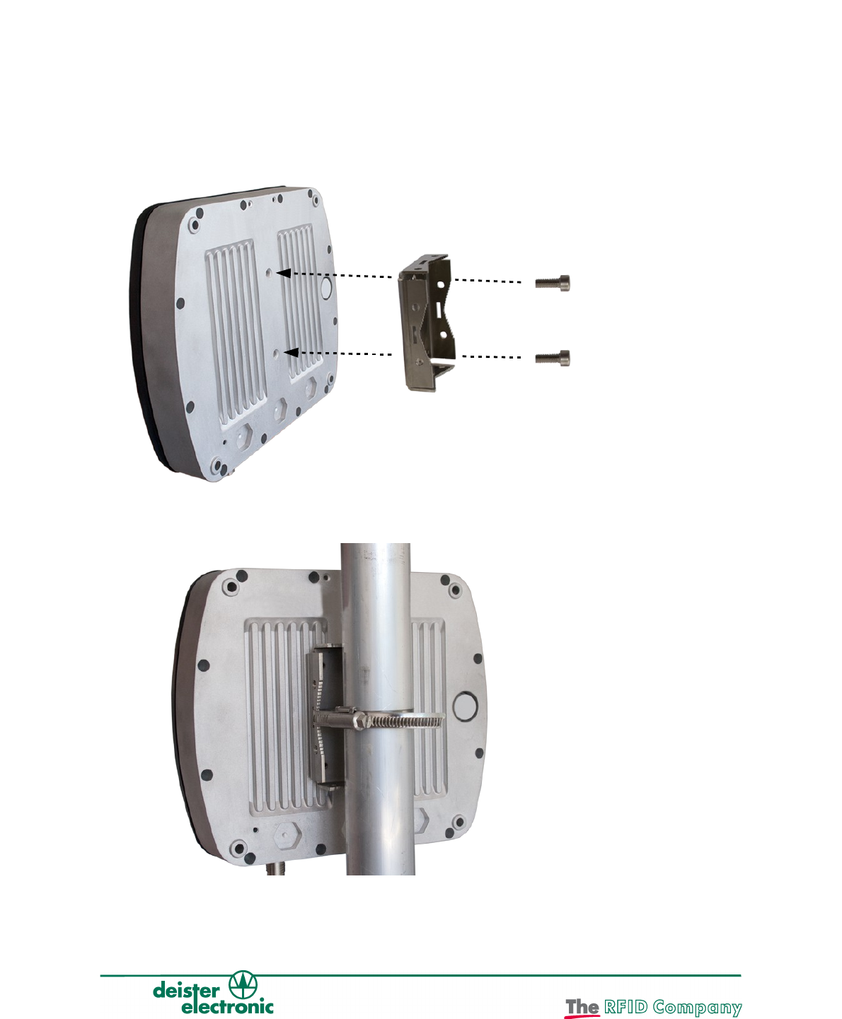
5. Mounting
5.1 Mounting on poles and pipes
For installation on a mast or tube, the baseplate LRM3 (included in scope of supply, see
Section 5.1.1) must be mounted on the rear of the TSU 200, so that it can be adjusted
vertically or horizontally. The serrated rear face of the LRM3 ensures that the reader can be
securely mounted and adjusted through 360°. For greater flexibility of installation and
adjustment of the TSU 200 on masts or tubes, we recommend use of the ball-joint
mounting LRM1 (optional, see Section 5.2.1).
5.1.1 Mounting the base plate for mast mounting LRM3
10 Zulassung_wi_en_ts_tsu-200_pro_v140205_te_bf
Use Allen screws M6x8 !
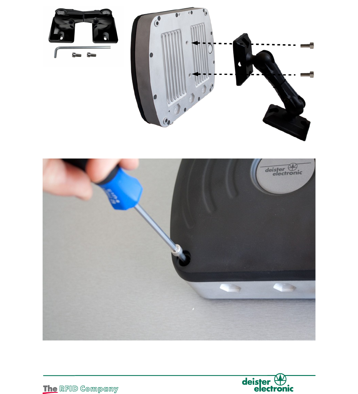
5.2 Montage on walls and ceilings
For mounting on walls or ceilings the ball joint bracket LRM1 (optional, see chapter 5.2.1) can
be mounted directly onto the back of the reader. This mounting aid allows to adjust the reader
in any desired position. Both ends of the ball joint bracket are ball-beared and connected via a
rotatable axis. The desired position can be fixed with the included 3/8” Allen wrench.
5.2.1 Mounting with ball joint bracket LRM1
5.2.2 Direct Mounting
To mount the unit directly use the holes provided in the front face of the unit.
Zulassung_wi_en_ts_tsu-200_pro_v140205_te_bf 11
Use Allen screws
M6x12 !

5.3 Function Principle and Environmental Influences
The reader sends a high-frequency carrier signal. The transponder that is located within
the area of this transmitted carrier transmits the signal back with its own transponder data
in a modulated way. This very weak signal is being analyzed by the reader.
Because of the particular small-bandwidth and the high carrier frequency this system is
almost fail-safe. Nevertheless the range of the reader can be negatively influenced. The
following list shows what to pay attention to:
1. The reader must have visual contact to the transponder. There must not be any
walls or other devices between reader and transponder. Reading through
plastic film, card board, papers or glass windows may be possible, but will reduce the
reading range depending on the condition of the material.
2. Water, ice and snow will absorb the carrier signal. Therefore the installer
has to make sure that the front of the reader and the transponder is not covered
with water, ice or snow.
3. Reflections within the surroundings of the reader can influence the reading result in
a negative way. Therefore the reader should be mounted as free-standing as
possible. We strictly discourage from sunk-in installations.
4. In Multi-Reader Environment (EU only), you must assign different channels to the readers.
To accomplish this, the parameter "preferred channel" should be adjusted accordingly
and you have to choose the highest possible channel spacing! When using UHF readers
that are installed close together (e.g. entrance and exit lane) it is recommended to pair
channels such as Channel 4, 10 and channel 7, 13 etc.
12 Zulassung_wi_en_ts_tsu-200_pro_v140205_te_bf
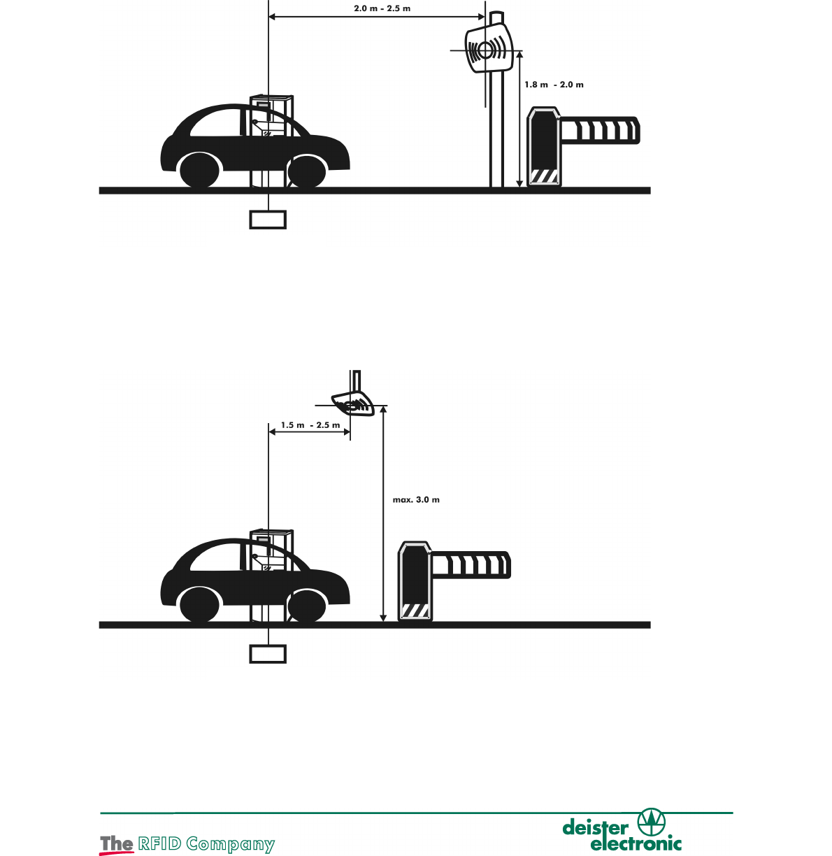
6. Installation Notes
For a standard installation in a passenger-car car park, a TSU 200 can be installed either
beside the roadway, or above it.
6.1 Installation on the side of the road:
The reader is mounted on a pole on the driver's side next to the road at a height of 1.8 m
– 2.0 m (5.9 – 6.5 ft.). Then the reader is aligned towards the transponder/car windshield.
When a ground loop is present, it should be used to trigger the reader. The distance from
the reader to the ground loop should be in the range of 2.0 m - 2.5 m (6.5 – 8.2 ft.).
6.2 Installation above the road
The reader should not be installed higher than 3.0 m (9.8 ft.) above the road. The distance from
the reader to the groundloop should be in the range of 1.5 m - 2.5 m (4.9 – 8.2 ft.). The reader is
slightly tilted towards the vehicle windshield, so that the reader is almost vertically aligned with the
windshield.
Note: The antenna beam of the reader shall in no case be restricted by objects above or below
the reader. Flush mounting is not recommended! If other types of vehicles (trucks, small cars etc)
need to be identified, the reader must be installed and aligned individually.
Zulassung_wi_en_ts_tsu-200_pro_v140205_te_bf 13
6.5 ft. – 8.2 ft.
5.9 ft. – 6.5 ft.
Ground Loop
4.9 ft. – 8.2 ft.
max. 9.8 ft.
Ground Loop
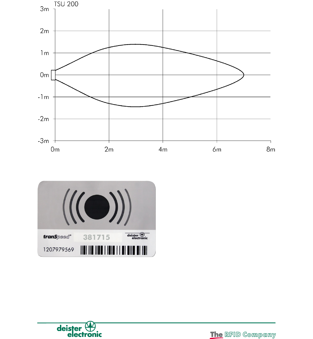
6.3 Reading Distance
Given the condition that the transponder is aligned towards the reader, a detection range as
shown in the figure below is the result when the reader is operated detached. The reading range
varies due to environmental influences. For example, reflections on the ground can increase the
maximum reading range. Walls, which are next to a reader, and a different transponder
orientation will lead to a deformation of the reading field. It is therefore recommended to check
the reading range after installation of the reader. See Chapter 7 "Test Mode".
Note: The values were determined with the "TPU 3080/3090" transponder.
Figure: TPU 3080 / 3090 Transponder
14 Zulassung_wi_en_ts_tsu-200_pro_v140205_te_bf
7. Test Mode
The TSU 200 has an integrated test mode for checking the performance of UHF
transponders, and to automatically adapt the unit's antenna to local environmental
conditions. This simplifies alignment of the unit and its adaptation to specific local
circumstances of the application. The test mode can be activated with the test transponder
TPU 3080T (Art. No. 1388.000) within 30 seconds after the unit is switched on. After
activation the antenna is first automatically adjusted. During this adjustment there must not
be any object directly in front of the antenna. Following this, for a period of five minutes,
each transponder in the field will be signalled by the three LEDs and the beeper. Using the
deister test transponder, the specified reading distance in an installed system can be
checked at any time.
Notification Status TSU 200
Yellow LED on for 30 seconds after switching on Waiting for test transponder
Red, green, yellow LED light sequence Test mode
All LEDs blink, beeper Transponder read in test mode
Zulassung_wi_en_ts_tsu-200_pro_v140205_te_bf 15
8. Configuration of WebConfig Software
8.1 Preparations
A virtual serial COM port is set up via the USB port. The driver installation is described in
the manual of the SNG 3.
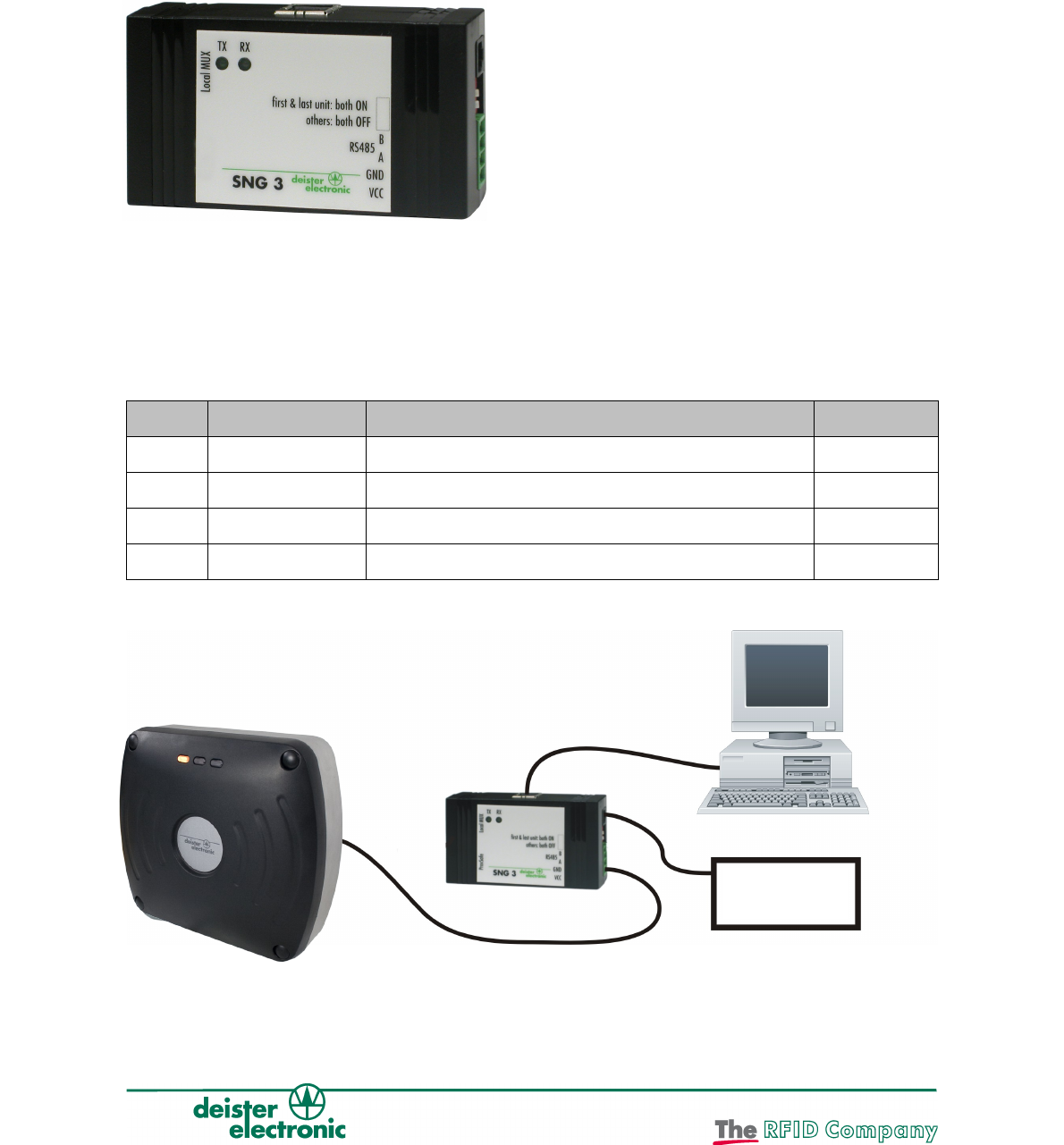
8.2 SNG 3 Interface Converter
The interface converter SNG3 (optional, see 9. “Accessories”) can be used for connecting
a reader to a host/PC via USB. Powering of the reader is carried out by the SNG3 as long
as it is connected to a power supply unit itself. To do so, a special wall power supply is
available (optional, also see 9. “Accessories”). The drivers needed can be found on the
CD within delivery.
SNG 3 Description Function TSU 200
Pin 1 +VCC supply voltage for TSU 200 (12...24 V/DC) Pin 1
Pin 2 GND ground Pin 3
Pin 3 RS485 - A RS485 interface, data line A Pin 2
Pin 4 RS485 - B RS485 interface, data line B Pin 4
Connect as follows:
16 Zulassung_wi_en_ts_tsu-200_pro_v140205_te_bf
Power
Supply

8.3 Starting WebConfig
After the successful installation of the virtual COM port driver, run the WebConfig
software. Copy the file "WebConfig.exe" from the supplied CD into a suitable directory on
your local hard disk and open it by double-clicking.
The configuration of the "TSU 200" must be carried out as follows:
Step Configuration Software “WebConfig.” Reader TSU 200
1 connect reader to
SNG3 (see table page
16), connect SNG3 to
PC via USB cable,
connect wall power
supply to SNG3
2 Start configuration software “WebConfig”
3 Select USB Serial Port
4 Click on „Device“ – „Search addresses“
5 Software searches for the reader which is connected to
the selected COM Port
6 After successful search the reader found will be indicated
7 Current reader configuration will be read
8 Configuration menu will open
9 Configuration can be modified by user
10 Transfer changed configuration to the reader by clicking
on “Apply Changes”
11 Reader will store the
new configuration
within its internal non-
volatile memory
12 End connection by clicking on “Offline”
13 Program will be closed by „File“ - „Exit“
Zulassung_wi_en_ts_tsu-200_pro_v140205_te_bf 17
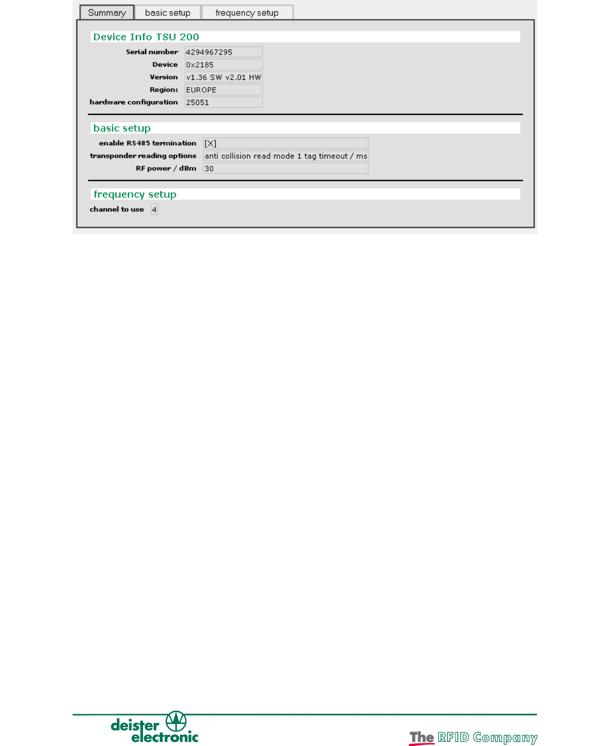
8.3.1 Summary
This menu shows a summary of the current reader configuration.
Device Info
Serial number: Serial number of device
Device: Identification code of device
Version: Firmware version (SW) and hardware version (HW) of device
Region: Region the device is authorized for
Hardware configuration: Hardware configuration code of device
Note:
The picture shows the frequency settings for a European unit. In countries such as e.g. the
United States the frequency setup may vary. See Fehler: Referenz nicht gefunden “Fehler:
Referenz nicht gefunden“.
18 Zulassung_wi_en_ts_tsu-200_pro_v140205_te_bf
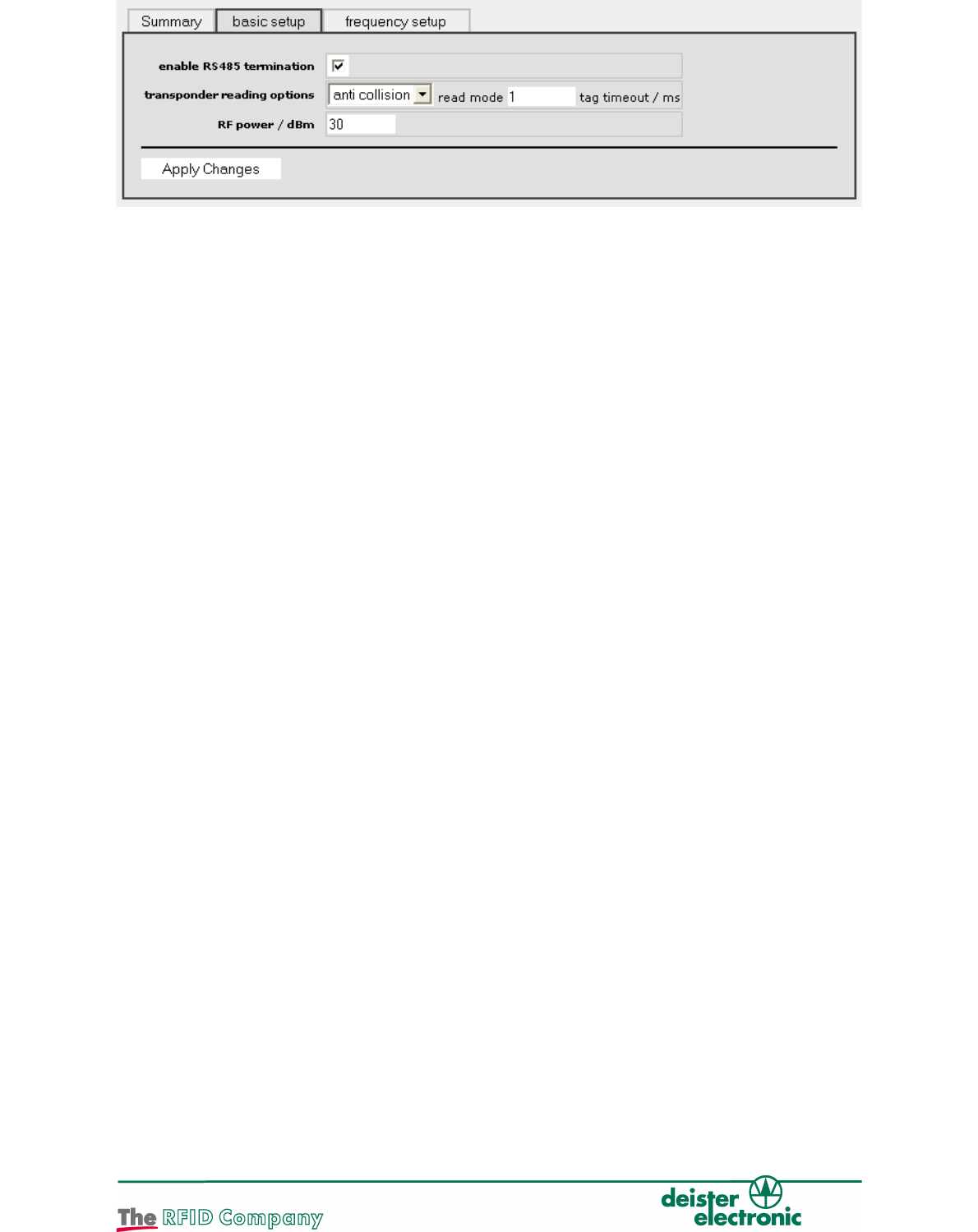
8.3.2 Basic Setup
Enable RS485 termination
If this check box is selected, the internal RS485 termination of the reader is switched on.
This function is permanently activated in the TSU 200!
read mode
This parameter defines, if the reader expects only one tag in the antenna field or if there
may be more tags within the antenna field. In case there are more tags, the reader has to
execute an anti collision algorithm. It is also possible to configure the reader to “single
shot” mode in which the read signaling for the same transponder is only done once or
after a timeout defined by parameter “tag timeout”.
Anti collision: Operating mode in case there is more than one tag in the field
single shot: Operating mode for reading tag data, in case there is only one tag
in the field. The tag data will be transmitted again after the time
specified in “tag timeout”.
Beim TSU 200 bleibt anti collision aktiviert!
tag timeout / ms (for read mode “single shot” only)
This value defines the interval (timeout) in milliseconds between transmissions of a tag in
"single shot" mode. After expiration of this interval it is signaled that the tag will be read
again. In the TSU 200 this value remains set to 65535.
RF power / dBm
This value defines the radiated power of the antenna in dBm. The maximum output power
of the antenna is 32 dBm.
Zulassung_wi_en_ts_tsu-200_pro_v140205_te_bf 19
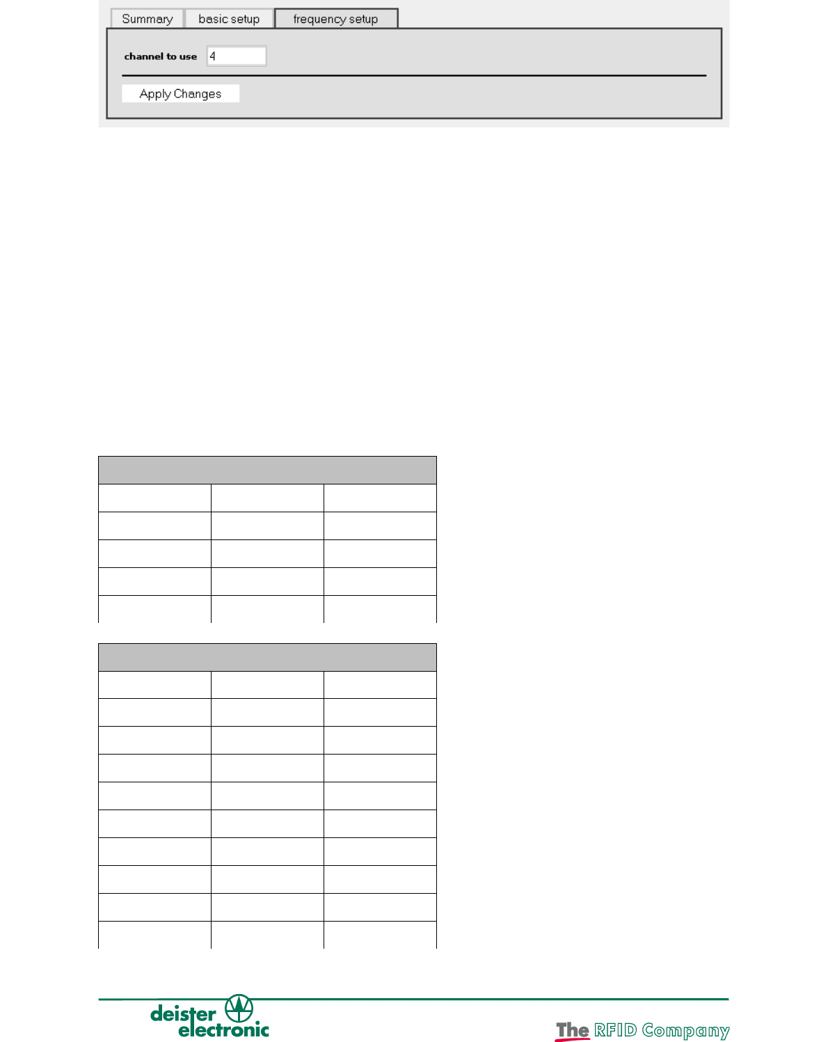
8.3.3 Frequency Setup
Preferred channel
This value defines the preferred channel number before the reader uses another channel.
In a multi-reader environment (EU only), use different channels for the readers. Use the
“Preferred channel” parameter to make this setting. Select the greatest possible separation!
Channel mask
This mask defines the channels to be used by the readers. Each activated checkbox
enables use of the appropriate channel (for further information, see also the section
Fehler: Referenz nicht gefunden “Fehler: Referenz nicht gefunden”).
Recommendation for configuration of UHF readers (EU only):
If several readers are installed close together (e.g. entry and exit lanes), then channel pairs
should be set up for them, for example, channels 4 and 10, and channels 7 and 13.
8.3.4 Frequencies
ETSI 302 208 v1.2
Channel No. Frequency E.R.P.
4 865.7 MHz ≤ 2.00 W
7 866.3 MHz ≤ 2.00 W
10 866.9 MHz ≤ 2.00 W
13 867.5 MHz ≤ 2.00 W
FCC Part 15 (US)
Channel No. Frequency E.I.R.P.
1 902.75 MHz ≤ 4.00 W
2 903.25 MHz ≤ 4.00 W
3 903.75 MHz ≤ 4.00 W
4 904.25 MHz ≤ 4.00 W
... ... ...
47 925.75 MHz ≤ 4.00 W
48 926.25 MHz ≤ 4.00 W
49 926.75 MHz ≤ 4.00 W
50 927.25 MHz ≤ 4.00 W
20 Zulassung_wi_en_ts_tsu-200_pro_v140205_te_bf

Korea
Channel No. Frequency E.I.R.P.
2 917.1 MHz ≤ 4.00 W
5 917.7 MHz ≤ 4.00 W
8 918.3 MHz ≤ 4.00 W
11 918.9 MHz ≤ 4.00 W
14 919.5 MHz ≤ 4.00 W
17 920.1 MHz ≤ 4.00 W
Japan
Channel No. Frequency E.I.R.P.
1 952.4 MHz ≤ 4.00 W
2 952.6 MHz ≤ 4.00 W
3 952.8 MHz ≤ 4.00 W
4 953.0 MHz ≤ 4.00 W
5 953.2 MHz ≤ 4.00 W
6 953.4 MHz ≤ 4.00 W
7 953.6 MHz ≤ 4.00 W
Singapore
Channel No. Frequency E.R.P.
1 920.25 MHz ≤ 2.00 W
2 920.75 MHz ≤ 2.00 W
3 921.25 MHz ≤ 2.00 W
4 921.75 MHz ≤ 2.00 W
5 922.25 MHz ≤ 2.00 W
6 922.75 MHz ≤ 2.00 W
7 923.25 MHz ≤ 2.00 W
8 923.75 MHz ≤ 2.00 W
9 924.25 MHz ≤ 2.00 W
10 924.75 MHz ≤ 2.00 W
Zulassung_wi_en_ts_tsu-200_pro_v140205_te_bf 21

Brazil
Channel No. Frequency E.R.P.
1 915.25 MHz ≤ 2.00 W
2 915.50 MHz ≤ 2.00 W
3 915.75 MHz ≤ 2.00 W
4 916.00 MHz ≤ 2.00 W
... ≤ 2.00 W
47 926.75 MHz ≤ 2.00 W
48 927.00 MHz ≤ 2.00 W
49 927.25 MHz ≤ 2.00 W
50 927.50 MHz ≤ 2.00 W
China
Channel No. Frequency E.R.P.
1 920,625 ≤ 2.00 W
2 920,875 ≤ 2.00 W
3 921,125 ≤ 2.00 W
4 921,375 ≤ 2.00 W
5 921,625 ≤ 2.00 W
6 921,875 ≤ 2.00 W
7 922,125 ≤ 2.00 W
8 922,375 ≤ 2.00 W
9 922,625 ≤ 2.00 W
10 922,875 ≤ 2.00 W
11 923,125 ≤ 2.00 W
12 923,375 ≤ 2.00 W
13 923,625 ≤ 2.00 W
14 923,875 ≤ 2.00 W
15 924,125 ≤ 2.00 W
16 924,375 ≤ 2.00 W
22 Zulassung_wi_en_ts_tsu-200_pro_v140205_te_bf

9. Accessories
Article Description Article No.
TPU3080T Windshield test transponder. Fixcoded, protected,
with deister logo
01388.000
CC2 Connection cable, grey, 3 m, M12 female
connector, straight, 4-pin
09287.101
CC4 Connection cable, grey, 3 m, M12 female
connector, straight, 4-pin to 4-pin Phoenix
connector
09287.301
CC4 Connection cable, grey, 10 m, M12 female
connector, straight, 4-pin to 4-pin Phoenix
connector
06236.000
LRM1 Ball joint bracket 06103.000
LRM3 Base plate for mast mounting 06106.000
AC/DC power supply
Euro
Power supply for expansion module, input voltage
230 VAC, output voltage 12 VDC (1 A), Friwo® plug
08812.000
AC/DC
power supply
International
Power supply, input voltage 100-230 VAC, incl.
adapter for USA/Japan and United Kingdom, output
voltage 12 VDC (1.25 A), Friwo® plug
06757.000
AC/DC Power Supply Power supply for c-rail mounting, input voltage 90-
260 VAC, 50-60 Hz output voltage 24 VDC (2.5 A)
06756.000
SNG3
Smart Network
Gateway
Interface converter USB-to-RS485, incl. USB
interface cable, Friwo® plug
(Power supply required)
08782.000
DBC deBus Converter, Interface converter for deBus
components, power supply 10-30 VDC
06232.000
IDC Controller for the connection to deBus-readers
power supply 10-30 VDC
06230.000
SIC1 Serial Interface Converter from RS485/deBus
protocol to Open Collector/Wiegand, Dataclock,
Magstripe protocol, power supply 10-30 VDC
06233.000
SIC2 Serial Interface Converter from RS485/deBus
protocol to RS485/customized protocol, power
supply 10-30 VDC
06234.000
SIC3 Serial Interface Converter from RS485/deBus
protocol to RS232, power supply 10-30 VDC
06235.000
Zulassung_wi_en_ts_tsu-200_pro_v140205_te_bf 23
Headquarters
Germany:
deister electronic GmbH
Hermann-Bahlsen Str. 11
30890 Barsinghausen
Tel.: +49 (0) 51 05 - 51 61 11
Fax: +49 (0) 51 05 - 51 62 17
info.de@deister.com
www.deister.com
Japan:
deister electronic Japan, LTD.
Toshiba Hoshikawa Bldg. 4F
2-4 Kawabe-chô
Hodogaya-ku, Yokohama-shi
Kanagawa, 240-0001
Tel.: +81 (0) 45 340 1831
Fax: +81 (0) 45 340 1801
info.jp@deister.com
Americas and Caribbean:
Deister Electronics USA, Inc.
9303 Grant Avenue
Manassas, VA 20110
Tel.: +1 703 - 368 2739
Fax: +1 703 - 368 9791
info.us@deister.com
Singapore:
Coselec Pte Ltd.
339158 #06-12/14 Singapore
Blk 28 Kallang Place
info.sg@deister.com
+65 6741 5200
+65 6741 6200
Benelux:
deister electronic office
Business Park E 19
Battelsesteenweg 455/A
2800 Mechelen
Tel.: +32 (0) 15 - 28 09 68
Fax: +32 (0) 15 - 28 09 71
info.be@deister.com
France:
deister electronic france
101 rue Pierre Semard
92320 Chatillon
Tel.: +33 (0) 1 47 - 35 78 78
Fax: +33 (0) 1 47 - 35 92 59
info.fr@deister.com
Great Britain:
deister electronic (UK) Ltd.
Stapleton Way, Enterprise Park
Spalding, Lincolnshire
PE11 3YQ
Tel.: +44 (0) 1775 - 717100
Fax: +44 (0) 1775 - 717101
info.uk@deister.com