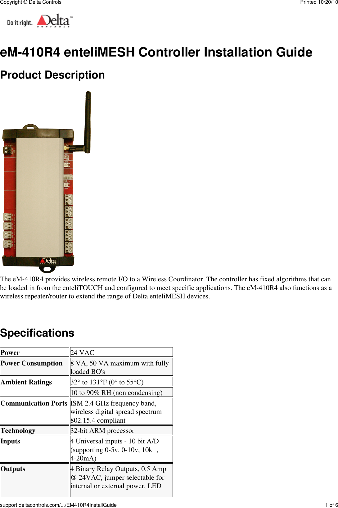
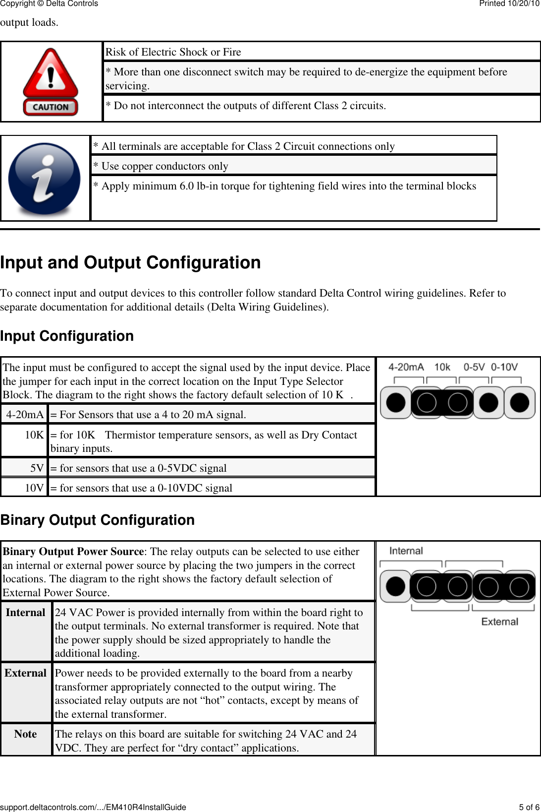
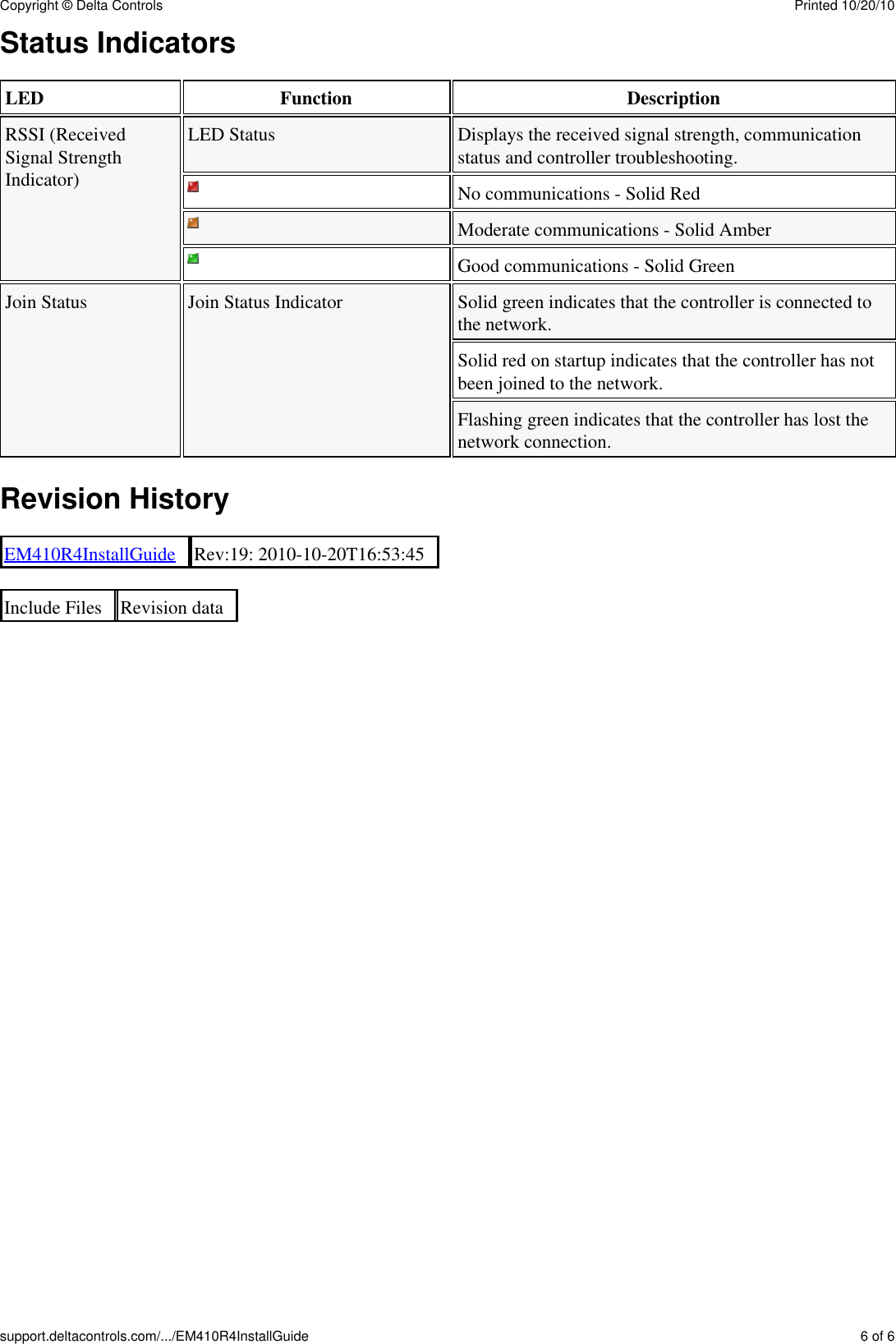
Delta Controls EM410R4 WIRELESS FIELD MODULE WITH 4 UIs, 1 AO AND 4 BOs User Manual

Delta Controls Inc. WIRELESS FIELD MODULE WITH 4 UIs, 1 AO AND 4 BOs Users Manual

Users Manual

eM-410R4 enteliMESH Controller Installation GuideProduct DescriptionThe eM-410R4 provides wireless remote I/O to a Wireless Coordinator. The controller has fixed algorithms that canbe loaded in from the enteliTOUCH and configured to meet specific applications. The eM-410R4 also functions as awireless repeater/router to extend the range of Delta enteliMESH devices.SpecificationsPower 24 VACPower Consumption 8 VA, 50 VA maximum with fullyloaded BO'sAmbient Ratings 32° to 131°F (0° to 55°C)10 to 90% RH (non condensing)Communication Ports ISM 2.4 GHz frequency band,wireless digital spread spectrum802.15.4 compliantTechnology 32-bit ARM processorInputs 4 Universal inputs - 10 bit A/D(supporting 0-5v, 0-10v, 10kΩ,4-20mA)Outputs 4 Binary Relay Outputs, 0.5 Amp@ 24VAC, jumper selectable forinternal or external power, LEDCopyright © Delta Controls Printed 10/20/10support.deltacontrols.com/.../EM410R4InstallGuide 1 of 6
status indication1 Analog Output (0-10 VDC)Compliance CE (ETSI)ICFCC, Class B, Part 15Listings UL916Listings and Compliance Declaration available for download at https://support.deltacontrols.comPackage ContentsProduct: eM-410R4 enteliMESH Controller• eM-410R4 Installation Guide• Related DocumentsenteliMESH Application Guide• ORCAview Technical Reference Guide• enteliTOUCH User Guide• Cautions and WarningsThis controller is an Electro-statically sensitive device. Proper ESD protection (ground strap) shouldbe used when installing this product so that damage to the product does not occur.Equipment damage or loss of data may occur if these procedures are not followed as specified.Installations requiring CE conformance: All wiring for CE rated products must use an extra lowvoltage (SELV) or protective extra low voltage (PELV) transformer. Use safety-isolatingtransformers, (Class II transformer) per EN61558. The transformer must be rated for 100% dutycycle.This device complies with Part 15 of the FCC Rules. Operation is subject to the following twoconditions.(1) This device may not cause harmful interference and(2) This device must accept any interference received including interference that may causeundesired operation.FCC ID: YRR-eM410R4IC ID: 9100A-eM410R4Mounting and DimensionsThe includes a plastic enclosure that can be quickly mounted with two screws (not provided). This controller shouldbe mounted in an appropriate location within packaged equipment or another enclosure that meets code requirements.Dimension mm±0.5 inchesPCB width 100 4PCB length 184 7 1/4Copyright © Delta Controls Printed 10/20/10support.deltacontrols.com/.../EM410R4InstallGuide 2 of 6
A 101 4B 46.5 1 7/8C 191 7 1/2D 204 8E 217 8 1/2F 24 1G 12 1/2Mounting wireless product inside a metal enclosure may reduce signal strength. An optionalremote antenna can be used to extend the antenna and mount it externally on the enclosure.Board LayouteM-410R4 Layout DrawingFeature eM-410R4Automatic ChannelSelectionAutomatic PAN IDSelectionAutomatic DeviceAddress SelectionBattery PoweredHybrid PoweredCopyright © Delta Controls Printed 10/20/10support.deltacontrols.com/.../EM410R4InstallGuide 3 of 6
AC PoweredOptional AntennaMountingRouting CapableInputsOutputssubPAN CapableFixed AlgorithmPower WiringMost Delta Controls devices use a 24Vac Class 2, half wave rectified power supply (excluding DSM-050,ADM-2W704, which are FULL wave rectified). A single transformer may be used to power multiple controllersand/or auxiliary field devices (actuators, etc) provided the following conditions are met:All devices MUST be half wave rectified. Mixing power between half wave and full wave rectified deviceswill damage both the transformer and connected equipment.• The transformer is properly sized, including line losses for the total VA requirements.• Polarity is observed between controllers (with respect to 24~ and Gnd).• The transformer secondary is fused for its maximum rated load (4A max for Class 2 circuits).• General WiringAll wiring must conform to NEC and local codes and regulations. Use earth ground isolating step-down Class 2transformers. Do not use autotransformers. Determine supply transformer rating by summing total VA of product andCopyright © Delta Controls Printed 10/20/10support.deltacontrols.com/.../EM410R4InstallGuide 4 of 6
output loads.Risk of Electric Shock or Fire* More than one disconnect switch may be required to de-energize the equipment beforeservicing.* Do not interconnect the outputs of different Class 2 circuits.* All terminals are acceptable for Class 2 Circuit connections only* Use copper conductors only* Apply minimum 6.0 lb-in torque for tightening field wires into the terminal blocksInput and Output ConfigurationTo connect input and output devices to this controller follow standard Delta Control wiring guidelines. Refer toseparate documentation for additional details (Delta Wiring Guidelines).Input ConfigurationThe input must be configured to accept the signal used by the input device. Placethe jumper for each input in the correct location on the Input Type SelectorBlock. The diagram to the right shows the factory default selection of 10 KΩ.4-20mA = For Sensors that use a 4 to 20 mA signal.10K = for 10KΩ Thermistor temperature sensors, as well as Dry Contactbinary inputs.5V = for sensors that use a 0-5VDC signal10V = for sensors that use a 0-10VDC signalBinary Output ConfigurationBinary Output Power Source: The relay outputs can be selected to use eitheran internal or external power source by placing the two jumpers in the correctlocations. The diagram to the right shows the factory default selection ofExternal Power Source.Internal 24 VAC Power is provided internally from within the board right tothe output terminals. No external transformer is required. Note thatthe power supply should be sized appropriately to handle theadditional loading.External Power needs to be provided externally to the board from a nearbytransformer appropriately connected to the output wiring. Theassociated relay outputs are not “hot” contacts, except by means ofthe external transformer.Note The relays on this board are suitable for switching 24 VAC and 24VDC. They are perfect for “dry contact” applications.Copyright © Delta Controls Printed 10/20/10support.deltacontrols.com/.../EM410R4InstallGuide 5 of 6
Status IndicatorsLED Function DescriptionRSSI (ReceivedSignal StrengthIndicator)LED Status Displays the received signal strength, communicationstatus and controller troubleshooting.No communications - Solid RedModerate communications - Solid AmberGood communications - Solid GreenJoin Status Join Status Indicator Solid green indicates that the controller is connected tothe network.Solid red on startup indicates that the controller has notbeen joined to the network.Flashing green indicates that the controller has lost thenetwork connection.Revision HistoryEM410R4InstallGuide Rev:19: 2010-10-20T16:53:45Include Files Revision dataCopyright © Delta Controls Printed 10/20/10support.deltacontrols.com/.../EM410R4InstallGuide 6 of 6

Navigation menu