Delta Controls EM410R4 WIRELESS FIELD MODULE WITH 4 UIs, 1 AO AND 4 BOs User Manual
Delta Controls Inc. WIRELESS FIELD MODULE WITH 4 UIs, 1 AO AND 4 BOs Users Manual
Users Manual
eM-410R4 enteliMESH Controller Installation Guide
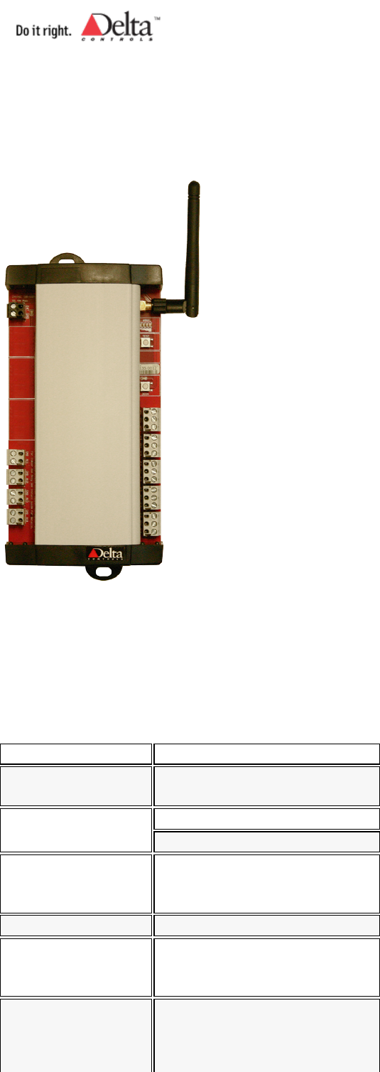
Product Description
The eM-410R4 provides wireless remote I/O to a Wireless Coordinator. The controller has fixed algorithms that can
be loaded in from the enteliTOUCH and configured to meet specific applications. The eM-410R4 also functions as a
wireless repeater/router to extend the range of Delta enteliMESH devices.
Specifications
Power 24 VAC
Power Consumption 8 VA, 50 VA maximum with fully
loaded BO's
Ambient Ratings 32° to 131°F (0° to 55°C)
10 to 90% RH (non condensing)
Communication Ports ISM 2.4 GHz frequency band,
wireless digital spread spectrum
802.15.4 compliant
Technology 32-bit ARM processor
Inputs 4 Universal inputs - 10 bit A/D
(supporting 0-5v, 0-10v, 10kΩ,
4-20mA)
Outputs 4 Binary Relay Outputs, 0.5 Amp
@ 24VAC, jumper selectable for
internal or external power, LED
Copyright © Delta Controls Printed 10/20/10
support.deltacontrols.com/.../EM410R4InstallGuide 1 of 6
status indication
1 Analog Output (0-10 VDC)
Compliance CE (ETSI)
IC
FCC, Class B, Part 15
Listings UL916
Listings and Compliance Declaration available for download at https://support.deltacontrols.com
Package Contents
Product: eM-410R4 enteliMESH Controller• eM-410R4 Installation Guide•
Related Documents
enteliMESH Application Guide• ORCAview Technical Reference Guide• enteliTOUCH User Guide•
Cautions and Warnings
This controller is an Electro-statically sensitive device. Proper ESD protection (ground strap) should
be used when installing this product so that damage to the product does not occur.
Equipment damage or loss of data may occur if these procedures are not followed as specified.
Installations requiring CE conformance: All wiring for CE rated products must use an extra low
voltage (SELV) or protective extra low voltage (PELV) transformer. Use safety-isolating
transformers, (Class II transformer) per EN61558. The transformer must be rated for 100% duty
cycle.
This device complies with Part 15 of the FCC Rules. Operation is subject to the following two
conditions.
(1) This device may not cause harmful interference and
(2) This device must accept any interference received including interference that may cause
undesired operation.
FCC ID: YRR-eM410R4
IC ID: 9100A-eM410R4
Mounting and Dimensions
The includes a plastic enclosure that can be quickly mounted with two screws (not provided). This controller should
be mounted in an appropriate location within packaged equipment or another enclosure that meets code requirements.
Dimension mm
±0.5 inches
PCB width 100 4
PCB length 184 7 1/4
Copyright © Delta Controls Printed 10/20/10
support.deltacontrols.com/.../EM410R4InstallGuide 2 of 6
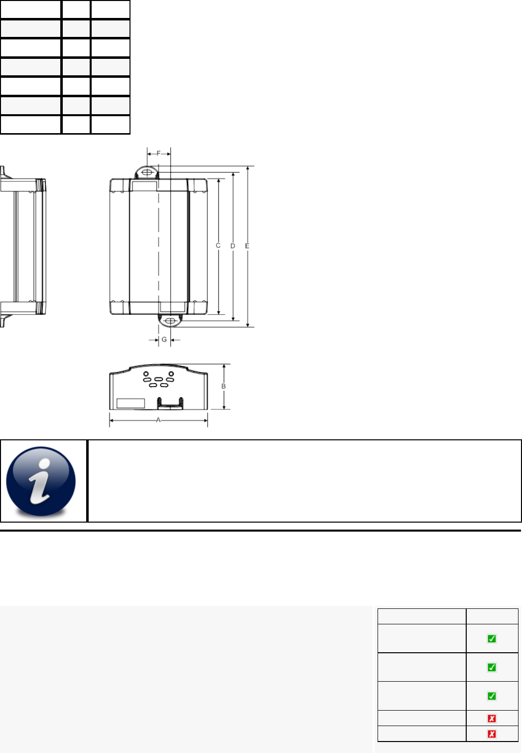
A 101 4
B 46.5 1 7/8
C 191 7 1/2
D 204 8
E 217 8 1/2
F 24 1
G 12 1/2
Mounting wireless product inside a metal enclosure may reduce signal strength. An optional
remote antenna can be used to extend the antenna and mount it externally on the enclosure.
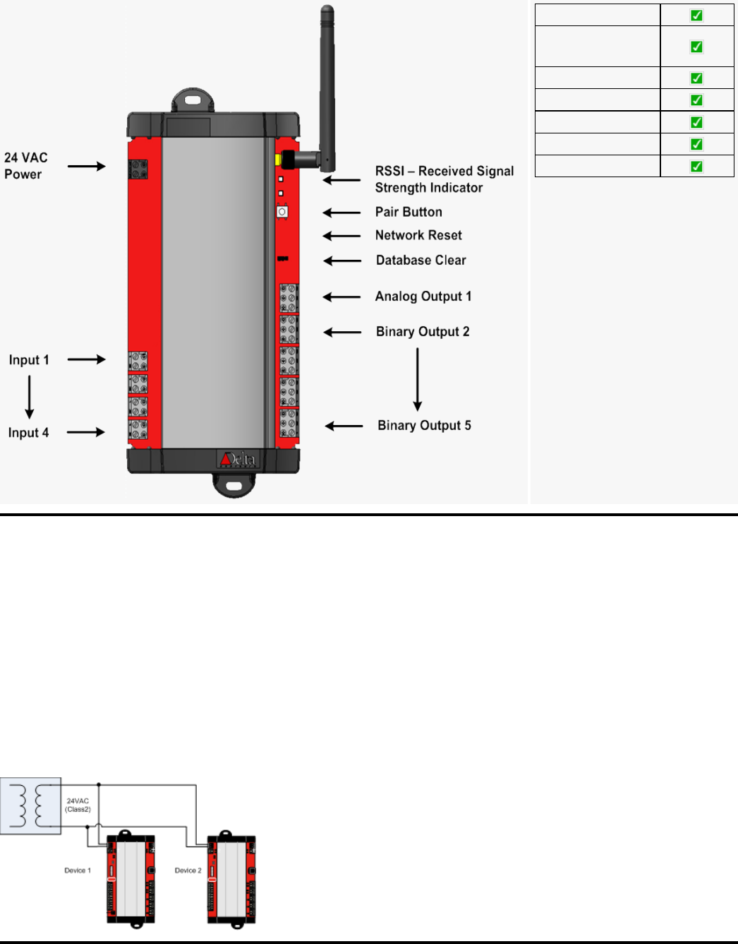
Board Layout
eM-410R4 Layout Drawing
Feature eM-410R4
Automatic Channel
Selection
Automatic PAN ID
Selection
Automatic Device
Address Selection
Battery Powered
Hybrid Powered
Copyright © Delta Controls Printed 10/20/10
support.deltacontrols.com/.../EM410R4InstallGuide 3 of 6
AC Powered
Optional Antenna
Mounting
Routing Capable
Inputs
Outputs
subPAN Capable
Fixed Algorithm
Power Wiring
Most Delta Controls devices use a 24Vac Class 2, half wave rectified power supply (excluding DSM-050,
ADM-2W704, which are FULL wave rectified). A single transformer may be used to power multiple controllers
and/or auxiliary field devices (actuators, etc) provided the following conditions are met:
All devices MUST be half wave rectified. Mixing power between half wave and full wave rectified devices
will damage both the transformer and connected equipment.
•
The transformer is properly sized, including line losses for the total VA requirements.• Polarity is observed between controllers (with respect to 24~ and Gnd).• The transformer secondary is fused for its maximum rated load (4A max for Class 2 circuits).•
General Wiring
All wiring must conform to NEC and local codes and regulations. Use earth ground isolating step-down Class 2
transformers. Do not use autotransformers. Determine supply transformer rating by summing total VA of product and
Copyright © Delta Controls Printed 10/20/10
support.deltacontrols.com/.../EM410R4InstallGuide 4 of 6
output loads.
Risk of Electric Shock or Fire
* More than one disconnect switch may be required to de-energize the equipment before
servicing.
* Do not interconnect the outputs of different Class 2 circuits.
* All terminals are acceptable for Class 2 Circuit connections only
* Use copper conductors only
* Apply minimum 6.0 lb-in torque for tightening field wires into the terminal blocks
Input and Output Configuration
To connect input and output devices to this controller follow standard Delta Control wiring guidelines. Refer to
separate documentation for additional details (Delta Wiring Guidelines).
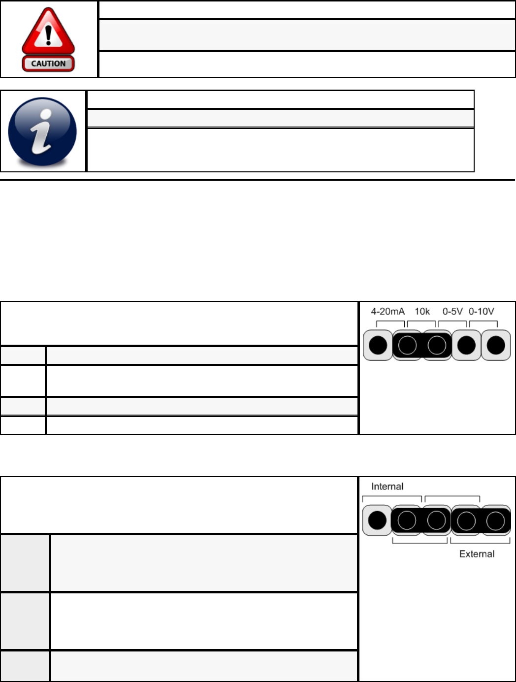
Input Configuration
The input must be configured to accept the signal used by the input device. Place
the jumper for each input in the correct location on the Input Type Selector
Block. The diagram to the right shows the factory default selection of 10 KΩ.
4-20mA = For Sensors that use a 4 to 20 mA signal.
10K = for 10KΩ Thermistor temperature sensors, as well as Dry Contact
binary inputs.
5V = for sensors that use a 0-5VDC signal
10V = for sensors that use a 0-10VDC signal
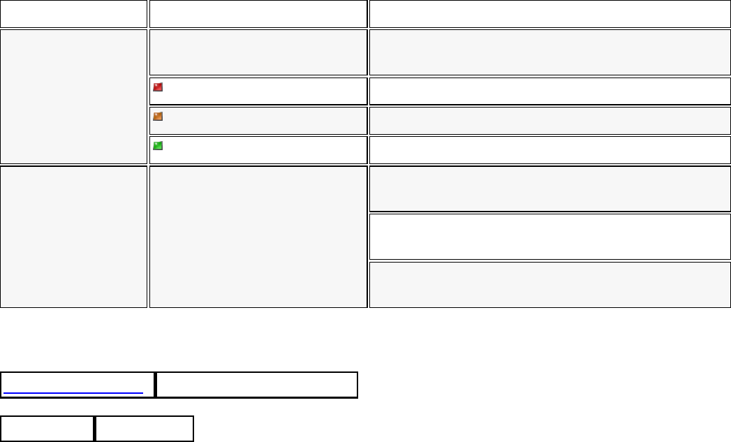
Binary Output Configuration
Binary Output Power Source: The relay outputs can be selected to use either
an internal or external power source by placing the two jumpers in the correct
locations. The diagram to the right shows the factory default selection of
External Power Source.
Internal 24 VAC Power is provided internally from within the board right to
the output terminals. No external transformer is required. Note that
the power supply should be sized appropriately to handle the
additional loading.
External Power needs to be provided externally to the board from a nearby
transformer appropriately connected to the output wiring. The
associated relay outputs are not “hot” contacts, except by means of
the external transformer.
Note The relays on this board are suitable for switching 24 VAC and 24
VDC. They are perfect for “dry contact” applications.
Copyright © Delta Controls Printed 10/20/10
support.deltacontrols.com/.../EM410R4InstallGuide 5 of 6
Status Indicators
LED Function Description
RSSI (Received
Signal Strength
Indicator)
LED Status Displays the received signal strength, communication
status and controller troubleshooting.
No communications - Solid Red
Moderate communications - Solid Amber
Good communications - Solid Green
Join Status Join Status Indicator Solid green indicates that the controller is connected to
the network.
Solid red on startup indicates that the controller has not
been joined to the network.
Flashing green indicates that the controller has lost the
network connection.
Revision History
EM410R4InstallGuide Rev:19: 2010-10-20T16:53:45
Include Files Revision data
Copyright © Delta Controls Printed 10/20/10
support.deltacontrols.com/.../EM410R4InstallGuide 6 of 6