Deltanode Solutions DDR003 700MHz Full Band Cellular Remote (33dBm) User Manual Fiber Distributed Antenna System DAS
Deltanode Solutions AB 700MHz Full Band Cellular Remote (33dBm) Fiber Distributed Antenna System DAS
Manual

Fiber Distributed Antenna System
(Fiber DAS)
Operation Manual
©
Copyright 2016
by Bird Technologies, Inc.
Instruction Book Part Number 920-Fiber-DAS Rev. P1
Delta Node® is a registered trademark of Delta Node Solutions Ltd. and Bird Technologies, Inc.

i
Safety Precautions
Thefollowingaregeneralsafetyprecautionsthatarenotnecessarilyrelatedtoanyspecificpartorprocedure,and
donotnecessarilyappearelsewhereinthispublication.Theseprecautionsmustbethoroughlyunderstoodand
applytoallphasesofoperationandmaintenance.
WARNING
KeepAwayFromLiveCircuits
OperatingPersonnelmustatalltimesobservegeneralsafetyprecautions.Donotreplacecomponentsormake
adjustmentstotheinsideofthetestequipmentwiththehighvoltagesupplyturnedon.Toavoidcasualties,
alwaysremovepower.
WARNING
ShockHazard
DonotattempttoremovetheRFtransmissionlinewhileRFpowerispresent.
WARNING
DoNotServiceOrAdjustAlone
Undernocircumstancesshouldanypersonreachintoanenclosureforthepurposeofserviceoradjustmentof
equipmentexceptinthepresenceofsomeonewhoiscapableofrenderingaid.
WARNING
SafetyEarthGround
Anuninterruptibleearthsafetygroundmustbesuppliedfromthemainpowersourcetotestinstruments.
Groundingoneconductorofatwoconductorpowercableisnotsufficientprotection.Seriousinjuryordeathcan
occurifthisgroundingisnotproperlysupplied.
WARNING
Resuscitation
Personnelworkingwithornearhighvoltagesshouldbefamiliarwithmodernmethodsofresuscitation.
WARNING
RemovePower
Observegeneralsafetyprecautions.Donotopentheinstrumentwiththepowerapplied.
SafetyPrecautions
ii
Safety Symbols
Note:
ThelaserusedinthissystemisaClass3blaserthatproducesinvisibleinfra‐redcoherent
light.Avoidlookingintoconnectedfibersandreceptacles.Notsafetoviewwithoptical
instruments.Alwaysputtheprotectioncapsonunusedfibersandreceptacles.
Callsattentiontosupplementalinformation.
WARNING
Warningnotescallattentiontoaprocedure,whichifnotcorrectlyperformed,couldresultinpersonalinjury.
CAUTION
Cautionnotescallattentiontoaprocedure,whichifnotcorrectlyperformed,couldresultindamagetothe
instrument.

FiberDistributedAntennaSystem(FiberDAS)
iii
Warning Statements
Thefollowingsafetywarningsappearinthetextwherethereisdangertooperatingandmaintenancepersonneland
arerepeatedhereforemphasis.
See
page38
ForCMRS817‐824MHzApplications:
See
page38
See
page11
Caution Statements
Thefollowingequipmentcautionsappearinthetextandarerepeatedhereforemphasis.
See
page46
WARNING
ThisisNOTaconsumerdevice.
ItisdesignforinstallationbyFCCLICENSEESandQUALIFIEDINSTALLERS.YouMUSThaveanFCCLICENSEor
expressconsentofanFCClicenseetooperatethisdevice.YouMUSTregisterClassBsignalboosters(asdefinedin
47CFR90.219)onlineatwww.fcc.gov/signal‐boosters/registration.Unauthorizedusemayresultin
significantforfeiturepenalties,includingpenaltiesinexcessof$100,000foreachcontinuingviolation.
WARNING
ThisisNOTaconsumerdevice.
ItisdesignforinstallationbyFCCLICENSEESandQUALIFIEDINSTALLERS.YouMUSThaveanFCCLICENSEor
expressconsentofanFCClicenseetooperatethisdevice.Unauthorizedusemayresultinsignificantforfeiture
penalties,includingpenaltiesinexcessof$100,000foreachcontinuingviolation.
WARNING
Avoidlookingintoconnectedfibersandreceptacles.
ThelaserusedinthissystemisaClass3blaserthatproducesinvisibleinfra‐redcoherentlight.Notsafetoview
withopticalinstruments.Alwaysputtheprotectioncapsonunusedfibersandreceptacles.
CAUTION
TurnOffTestTone
Donotforgettoturnoffthetesttonewhenyouaredonewithyouruplink.Bettercheckoneextratime.Theywill
otherwiseinterferewiththenormaloperationofthesystembycausingnoisetothebasestation.

SafetyPrecautions
iv
Safety Statements
USAGE
ANY USE OF THIS INSTRUMENT IN A MANNER NOT SPECIFIED BY THE MANUFACTURER MAY
IMPAIR THE INSTRUMENT’S SAFETY PROTECTION.
USO
EL USO DE ESTE INSTRUMENTO DE MANERA NO ESPECIFICADA POR EL FABRICANTE, PUEDE
ANULAR LA PROTECCIÓN DE SEGURIDAD DEL INSTRUMENTO.
BENUTZUNG
WIRD DAS GERÄT AUF ANDERE WEISE VERWENDET ALS VOM HERSTELLER BESCHRIEBEN,
KANN DIE GERÄTESICHERHEIT BEEINTRÄCHTIGT WERDEN.
UTILISATION
TOUTE UTILISATION DE CET INSTRUMENT QUI N’EST PAS EXPLICITEMENT PRÉVUE PAR LE
FABRICANT PEUT ENDOMMAGER LE DISPOSITIF DE PROTECTION DE L’INSTRUMENT.
IMPIEGO
QUALORA QUESTO STRUMENTO VENISSE UTILIZZATO IN MODO DIVERSO DA COME
SPECIFICATO DAL PRODUTTORE LA PROZIONE DI SICUREZZA POTREBBE VENIRNE
COMPROMESSA.

FiberDistributedAntennaSystem(FiberDAS)
v
SERVICE
SERVICING INSTRUCTIONS ARE FOR USE BY SERVICE - TRAINED PERSONNEL ONLY. TO AVOID
DANGEROUS ELECTRIC SHOCK, DO NOT PERFORM ANY SERVICING UNLESS QUALIFIED TO DO
SO.
SERVICIO
LAS INSTRUCCIONES DE SERVICIO SON PARA USO EXCLUSIVO DEL PERSONAL DE SERVICIO
CAPACITADO. PARA EVITAR EL PELIGRO DE DESCARGAS ELÉCTRICAS, NO REALICE NINGÚN
SERVICIO A MENOS QUE ESTÉ CAPACITADO PARA HACERIO.
WARTUNG
ANWEISUNGEN FÜR DIE WARTUNG DES GERÄTES GELTEN NUR FÜR GESCHULTES
FACHPERSONAL.
ZUR VERMEIDUNG GEFÄHRLICHE, ELEKTRISCHE SCHOCKS, SIND WARTUNGSARBEITEN
AUSSCHLIEßLICH VON QUALIFIZIERTEM SERVICEPERSONAL DURCHZUFÜHREN.
ENTRENTIEN
L’EMPLOI DES INSTRUCTIONS D’ENTRETIEN DOIT ÊTRE RÉSERVÉ AU PERSONNEL FORMÉ AUX
OPÉRATIONS D’ENTRETIEN. POUR PRÉVENIR UN CHOC ÉLECTRIQUE DANGEREUX, NE PAS
EFFECTUER D’ENTRETIEN SI L’ON N’A PAS ÉTÉ QUALIFIÉ POUR CE FAIRE.
ASSISTENZA TECNICA
LE ISTRUZIONI RELATIVE ALL’ASSISTENZA SONO PREVISTE ESCLUSIVAMENTE PER IL
PERSONALE OPPORTUNAMENTE ADDESTRATO. PER EVITARE PERICOLOSE SCOSSE
ELETTRICHE NON EFFETTUARRE ALCUNA RIPARAZIONE A MENO CHE QUALIFICATI A FARLA.

AboutThisManual
vi
About This Manual
Thismanualcoverstheoperating&maintenanceinstructionsforthefollowingmodels:
Changes to this Manual
Wehavemadeeveryefforttoensurethismanualisaccurate.Ifyoudiscoveranyerrors,orifyouhavesuggestions
forimprovingthismanual,pleasesendyourcommentstoourSolon,Ohiofactory.Thismanualmaybeperiodically
updated.Wheninquiringaboutupdatestothismanualrefertothepartnumber:920‐Fiber‐DAS;andrevision:P1.
Chapter Layout
Introduction — DescribesthefundamentalsoftheDeltaNodeFiber‐DASandprovidesalistofcommonlyused
abbreviationsandacronyms.
System Description — DescribestheMajorcomponentsthatmakeupaDeltaNodeFiber‐DASsystem.
System Design — IntroducesLinkBudgetcalculations,andtheelementsofdesigningaFiber‐DASsystem.
Installation Guidelines — ProvidesFCCrequirementsandsafetyconsiderationswheninstallingaDeltaNode
Fiber‐DAS.
Commissioning — Liststhepreparationsandequipmentrequiredtosuccessfullyinstallandcommissionthe
DeltaNodeFiber‐DAS.
RF Commissioning — Chaptercontainsusefuladviceonhowtodesignawellworkingsystemaswellas
examplesforfinetuninglinkabudgetandcontrollingnoiseinaDeltaNodeFiber‐DAS.
Model Identification — ProvidesabreakdownoftheDeltaNodepartnumbersfortheFiber‐DASsystems.Atable
ofpartnumbersusedforRemoteUnitsisalsoprovided.
DeltaNodeFiber‐DAS
1
Table of Contents
SafetySymbols................................................................................ii
WarningStatements...........................................................................iii
CautionStatements...........................................................................iii
SafetyStatements..............................................................................iv
ChangestothisManual.........................................................................vi
ChapterLayout................................................................................vi
Chapter 1 Introduction . . . . . . . . . . . . . . . . . . . . . . . . . . . . . . . . . . . . . . . . . . . . . . . . . . . . . . . . . . . . . . . 1
RFonfiber....................................................................................1
Definitions....................................................................................2
Chapter 2 System Description. . . . . . . . . . . . . . . . . . . . . . . . . . . . . . . . . . . . . . . . . . . . . . . . . . . . . . . . . 4
MasterUnit...................................................................................4
MasterFrameUnit(MFU)....................................................................4
BaseStationInterfaceUnit(BIU)...............................................................6
PointofInterconnect(POI) ..................................................................10
FiberOpticInterface(FOI)unit...............................................................11
PSU–therackpowersupply.................................................................15
BaseStationMasterunitGateway(BGW)......................................................16
RGW–thecompactremotegateway..........................................................17
RemoteUnit(RU).............................................................................18
DDR.....................................................................................19
DDS.....................................................................................22
DDH.....................................................................................23
DMU–Remoteheadend...................................................................25
Chapter 3 System design. . . . . . . . . . . . . . . . . . . . . . . . . . . . . . . . . . . . . . . . . . . . . . . . . . . . . . . . . . . . 27
TheBasics...................................................................................27
LinkBudgets.................................................................................27
Downlink.................................................................................28
Uplink....................................................................................28
Multiplebands...............................................................................33
Multipleoperators............................................................................34
Basestationinterface.......................................................................34
RemoteUnit..............................................................................34
FOI......................................................................................34
POI......................................................................................34
Fullsystemexample...........................................................................35
Chapter 4 Installation guidelines . . . . . . . . . . . . . . . . . . . . . . . . . . . . . . . . . . . . . . . . . . . . . . . . . . . . . 38
HealthandSafety.............................................................................38
InstallingtheMasterUnitandRemotes...........................................................38
SafetyandCareforfibers......................................................................39
Chapter 5 Commissioning . . . . . . . . . . . . . . . . . . . . . . . . . . . . . . . . . . . . . . . . . . . . . . . . . . . . . . . . . . 40
Preparations.................................................................................40
Necessarytools............................................................................40
Software.................................................................................40
Chapter 6 RF Commissioning . . . . . . . . . . . . . . . . . . . . . . . . . . . . . . . . . . . . . . . . . . . . . . . . . . . . . . . . 41
Settinguptheuplink..........................................................................41
NoiseloadonRadioBaseStation.............................................................42
Practicalapproach.........................................................................44

2
Chapter 7 Model Identification . . . . . . . . . . . . . . . . . . . . . . . . . . . . . . . . . . . . . . . . . . . . . . . . . . . . . . . 47
SystemModelNumbers........................................................................47
RemoteEndUnitPartNumbers.................................................................48
PublicSafetyDDRModuleNumbers..........................................................48
CellularDDRModuleNumbers...............................................................48

1
Chapter 1 Introduction
ThismanualcontainsbothguidelinesonhowtodesignasystemusingtheDeltaNodefiberdistributedantenna
system(Fiber‐DAS)conceptandhowtoinstall,commissionandmaintainsuchasystemforthelifespanoftheentire
installation.Itwillalsocontainmanybitsofinformationregardinggeneralpracticesintheindustryaswellasother
information.
Whenothermanufacturershaveconvertedoff‐airrepeatersintofiber‐fedrepeaters,DeltaNodehasdevelopedthe
conceptfromscratchwithfiberdistributioninmindfromthestart.Thisallowsforextremelygoodradio
performanceandweareproudofthebestinclassnoisefigureoflessthan3dBforthewholesystem,remoteunit
antennaporttobasestationinterfaceport.
TheFiber‐DASfromDeltaNodeisalsoextremelyflexibleinitssolutionmeaningthatthesystemcanbetailoredfor
almostanyneeds.Becauseoftheflexibilitytherearealsomanyparametersthatcanbechangedbytheuser.This
manualattemptstoexplainnotonlywhattheydo,butalsohowtosetthemproperly.
Fiber-DAS calculator — TogetherwiththismanualyoushouldhavetheaidoftheFiber‐DAScalculator,thisisan
Excelspreadsheetwiththefollowingfeaturesgivingameasureonhowwellthesystemwillperform:
SystemNoiseFigurecalculator
Intermodulationperformancecalculator
Uplink/DownlinkBalance
Dynamicheadroom
RF on fiber
Afiberdistributedantennasystem(Fiber‐DAS)isaveryefficientwayoftransmittingradiosignalsoverlarge
distances.Uptoabout25kmoffiberbetweenthehead‐endandtheremoteunitisallowed,providingthattheradio
accesstechnology(RAN)donotsuffertimingissuesandthatthefiberlossiswithinthespecification.
Themainprincipleistouseaninfra‐redlightsourcewhichismodulatedwiththecombinedradiosignalsthatneeds
tobepropagated.Thefiberchannelsystemisultrawide‐band,rangingfrom88MHzupto2600MHzandthus
coveringmosttypesofradiocommunicationsystemssuchasFMbroadcast,VHFcommunicationradios,TETRA,
GSM,CDMA,WCDMAandotherradioaccesstechnologiesthatareavailable.
Thedynamicofthefiberisgoodenoughtotoleratemulti‐carrier,multi‐bandandmulti‐operatorsolutionsthisway,
butofcoursetheyallsharetheavailabledynamicsandifthereareaverylargenumberofcarriersthefiber
attenuationneedstobelookedatofcourse.
BecausemostlandmobileradiosystemsandcellularsystemsareusingFrequencyDivisionDuplex(FDD)thismeans
thatthereneedstobeeithertwoseparatefibers,onefortheuplink(signalsfromtheterminaltowardsthebase
station)andforthedownlink(signalsfromtheradiobasestationtowardstheterminal)ortheymaybemultiplexed
onthesamefiberusingdifferentwavelengths.
DeltaNodeFiber‐DASusewave‐lengthdivisionmultiplexing(WDM)asthenormalconfigurationfeaturingthe
following:.
Singlemodefiber
Angledconnectors
Opticalloss<15dB
Note: SeparateUL/DLfiberscanbeusedifitisnecessaryordesired.
Becausethemodulationisanaloguethesystemrequiresthefiberstobeofsinglemodetype.Allconnectorsusedin
DeltaNodeequipmentforFiber‐DASareofSC‐APCtypewitha7°angle.Itisveryimportantthatallconnectorsin
patchesetceterabetweentheMasterUnit(MU)andtheRemoteUnit(RU)areangled,otherwisereflectionsare
causedwhichwillcauseproblemswiththequalityofthesignalsthroughthesystem.

Introduction
2
Definitions
Thefollowingabbreviations,industrystandardlingoandacronymsareusedinthisdocument.
BGW BasestationGateway
BIU
Basestationinterface.AlsoknownastheDIU.ItistheelectricalinterfacebetweentheMaster
Unit(MU)andtheoperatorradiobasestationoranothersourcefortheradiosignals,suchasa
off‐airrepeater.
BTS SeeRBS.
DAS Adistributedantennasystem.Severalantennasconnectedtogetherinacoaxialnetworksothat
severalantennascanbefedasignalfromacentrallocation.
DL See“Downlink”
Downlink Thesignalsthataretransmittedfromabasestationtowardsaterminal(phone).
Fiber
Inthisdocumentitreferstothetelecommunicationfibersusedtotransmitmodulatedlightas
pulsesoranaloguevariationsonaglassfiber.TheDeltaNodeFiber‐DASsystemshouldusesingle‐
modefiberalways.
Fiber‐DAS
Ageneralnamefordistributionsystemsusingradiofrequencyonfiber(RFonFiber)technology.
DASmeans“DistributedAntennaSystem”whichreferstothepracticeofbuilding“spreading
nets”withcoaxialcables,splittersandantennastocoverlargerstructures.
FOI Fiber‐opticinterface.AlsoknownasDOI(DeltaNodeOpticalInterface)
FOR Fiber‐opticremoteinterface,partoftheRemoteUnitconnectingtothefiber.
GSM GlobalSystemforMobileCommunications
iDEN IntegratedDigitalEnhancedNetwork
LTE LongTer mEvolution
MU
MasterUnit.Thisisarackthatcontainsallthemodulesthatbuildsuptotheheadendinthe
system.ThisiswheretheradiobasestationsinterfacetotheFiber‐DASsystem.Thisisalsowhere
thedownlinksignalsfromthebasestationsareconvertedintolaserlightandsentoverthefiber‐
opticstotheRemoteUnit(RU)andtheuplinksignalsfromtheRUareconvertedtoradio
frequencysignalsandtransmittedtotheradiobasestation(RBS,BTS).
POI PointofInterconnect,RFsplitter/combinerunit
QMA TypeofRFConnector.QuickdisconnectversionofSMARFConnectors.SeeSMA
RBS RadioBaseStation.Theinfrastructureunitnormallyconnectedtotheantennasintheradio
accessnetwork(RAN)andsometimescalledjustBaseStationorBaseTransceiverStation(BTS).
RGW RemoteGatewayUnit
RU
RemoteUnit.Thisistheunitclosesttotheantennathatconvertsthedownlinksignalfromthe
fibertoradiofrequenciesanddistributesitovertheantennasystem.Inthereverse,theuplink
radiofrequenciesareconvertedtomodulatedlaserlightandtransmittedbacktotheMasterUnit
(MU).
SC‐APC
ThetypeofconnectorusedforallDeltaNodeopticalequipment.Itisrecommendedthatall
connectorsbetweentheMUandtheRUareofthistype.SC‐APcanalsobeacceptedinpatch
panels.AllconnectorsMUSTBEANGLEDtoavoidsignalreflectionsthataredetrimentaltothe
signalquality.Fibersneedtobeofsingle‐modetype.
Singlemode
fiber
Afiberwherethelightataspecifiedrangeofwavelengthsonlyhaveasinglepaththrough.Thisis
requiredforanaloguemodulatedsystemssuchastheDeltaNodeFiber‐DASsystem
SMA Sub‐miniatureversionA.ATypeofRFConnector.

FiberDistributedAntennaSystem(FiberDAS)
3
Switch Anetworkswitchisacomputernetworkingdevicethatconnectsdevicestogetheronacomputer
network.
TETRA TerrestrialTrunkedRadio.TETRAusesTimeDivisionMultipleAccess(TDMA)withfouruser
channelsononeradiocarrierand25kHzspacingbetweencarriers.
UL See“Uplink”
UMTS
UniversalMobileTelecommunicationsSystemisasystemwherebroadbandsignalingand
packeteddataareused.Thestandardsarehandledinthe3GPPgroupandthemostcommon
typeofmodulationisWCDMA.
UplinkThesignalsthataretransmittedfromtheterminal(phone)towardsthebasestation.
SC‐PC Atypeoffiber‐opticconnectorwhichisnotangledandshouldnotbeusedwithDeltaNodeFiber‐
DAS
SC‐UPC Ultra‐polishedfiber‐opticconnector.NotrecommendedwithDeltaNodeFiber‐DAS
RF
RadioFrequencies,denominatestherangeoftransversalelectromagneticwaveswitha
frequencyfrom3kHzto300GHz.Theupperendofthespectrumisoftenreferredtoas
microwavefrequencies.
WCDMA
W‐CDMA
WidebandCodeDivisionMultipleAccessisatechnologyemployedbybasestation
manufacturerswhomakeUMTSbasestations.Thistechnologyiscommonlyusedin3Gnetworks
andthemainmodulationemployedinEurope.
4
Chapter 2 System Description
TheFiber‐DASsystemconsistsoftwomajorparts.ThisistheMasterUnit(MU)andoneormoreRemoteUnits(RU)
connectedtotheMasterUnitviaopticalfibers.EachRemoteUnitneedstobeconnectedtoafiber,butuptofour
RU’scanshareasinglefiberlinkusingopticalsplitters.
Master Unit
TheMasterUnitconsistsofa19‐inchrackwithmodulesthatareselecteddependingonthesystemdesign.
GenerallyallMasterUnitscontain:
Powersupply
,AtleastoneBaseStationInterfaceUnit(BIU)
AtleastoneFiber‐OpticInterfacecard(FOI)
PointofInterconnect(POI)
Networkswitch‐connectscommunicationspathsbetweenthemodules
RemoteGatewayUnit(RGW)ortheBaseStationGatewayUnit(BGW)‐RGWisasmallercompact
embeddedsolutionwhiletheBGWisafullfeaturedLinuxserverthatcanbesetupinmanydifferent
ways
ThemasterunitwillassignIPaddressestoallthesubunitsintherackandalsofortheRemoteUnitswhentheyare
connectedtothesystemviathebuildinDHCPserverpresentintheRGWandBGWmodules.Thisiswillconfigure
itselfautomaticallyandcreateaprotectedsub‐netforthesystemitselfthatshouldnotbeconnecteddirectlytoa
LAN.
Forremotesupervisionagateway(RGWorBGW)isinstalled.Thegatewayactsasafirewallandwillmakesurethat
theinternaltrafficinthesystemstaysinternalandthatthewebinterfaceformonitoringandsupervisionaswellas
SNMPtrapforwardishandledasexpected.
Eachofthemoduleswillbedescribedinthefollowingsections.
Master Frame Unit (MFU)
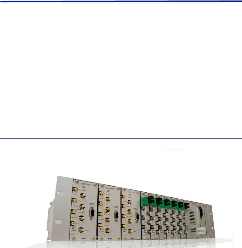
TheMasterFrameUnit(MFU)housesthePowerSupplies,FOIcardsandBIUs.
Figure1
showsanMFUequipped
with3BIUs,6FOIsandonePowerSupply.
Figure 1 Master Frame Unit

FiberDistributedAntennaSystem(FiberDAS)
5
Functional description
OneMFUsupportsseveralmoduleswhichcanbeplacedanywhereintheframeorasacombinationofseveral
differenttypesofunitsinaframe.Thereare16UpositionsintheMFUthatcanbeutilized,eachmoduletypehasa
differentwidth(seeeachmodule’sspecifications)sothenumberofmodulethatwillfitinanMFUvaries.OneMFU
canhouseupto4powersuppliesor8basestationinterfacecardsor16fiber‐opticinterfacecards.See
Table1
.
EachMFUneedsatleastonepowersupply,buttheydonotnecessarilyhavetobeplacedintheMFUthatthey
power.QuiteoftenasystemhasmorethanonepowersupplyandtheyareusuallyplacedtogetherinoneMFUfor
easyaccess.EachMFUhastwomolexconnectorsthatcanbeconnectedtoapowersupply.Thisallowsforaprimary
andaredundantpowersupplytobeconnectedtoittoensureoperationevenifonepowersupplyshouldfail.
TheMFUalsocontainsfansusedtoventilatetheunitshousedintheframe.Thesearehighqualityfansthathavea
highMTBF.
Table 1 MFU Specifications
Parameter Value
Inputvoltage 28VDC
Powerconnector Molex,10Pin
Ethernetconnector RJ45
Weight(withoutmodules) 2.5kg
Temperaturerange,Operational 0‐45°C
Width 19Inch
Height 3U
Depth 300mm
Maximumnumberofmodulessupported
PSU 4
BIU 8
FOI 16
SystemDescription
6
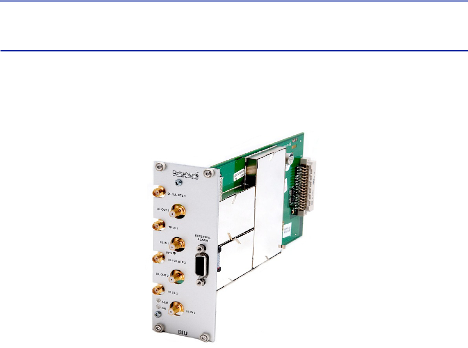
Base Station Interface Unit (BIU)
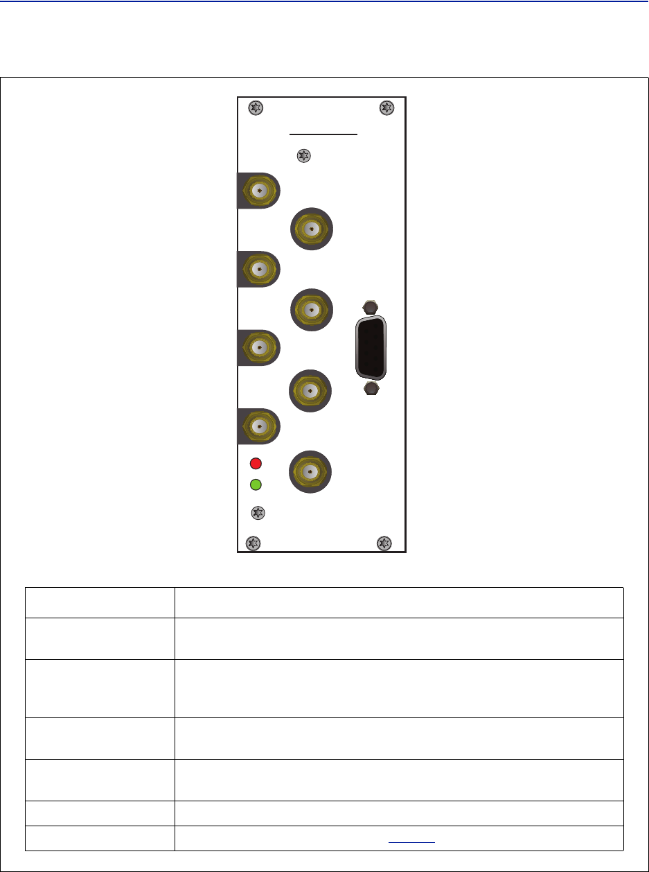
TheBaseStationInterfaceUnit(BIU)istheinterfacebetweentheoperator’sbasestationandtheFiber‐DASsystem.
ThismodulehasseveralRFconnectorsonthefrontpanelanditcontainsduplexfilters(optional)orseparateuplink/
downlinkpathswhichcanbechosendependingontheneedsfortheconnectiontothebasestation.Inmostcases
theduplexedversionwithacombinedDL/ULportisused.
Figure 2 Base Station Interface Unit (BIU)
Functional description
TheBIUhasfourSMAports(femaletype)toconnecttheRBS/BTS.IntheduplexedversioncombinedDL/UL
connectorsareusedtoconnecttotheRBS,andthereareULtest(TP)connectorspresentthatcanbeusedto
monitorthesignaloutfromtheBIU.IntheversionwithoutduplexfiltersthetestconnectorsreplacedbyUL
connectorsandthenormallycombinedUL/DLconnectorsarereplacedbyDLonlyconnectors.
TheBIUhasfourQMAports(femaletype)thatarenormallyusedtoconnectittoaPOI.Therearetwouplink(input)
portsandtwodownlink(output,TX)ports.Thesearetwoseparatepaths,theisolationbetweenDL1andDL2is>
50dBandtheisolationbetweentheUL1andUL2portsisalso>50dB.
TherearetwoseparateRFpathsintheBIUandtheBIUisconfiguredatthefactoryforthespecificfrequencybandit
willserve.ThetwopathsintheBIUcannothavedifferentfrequencies;aGSM900BIUwillhavetwoGSM900paths
andcannotbecombinedwithan1800path.SeparatefrequenciesrequireanadditionalBIUcardtobeinserted.
RFpatchcablesareusedtopatchtheDLandULpathstothePOI.
ThereisanalarmportontheBIUwhich(futureupgrade)canbeusedtoconnectexternalalarms.ThisisaDB9
femaleconnector.
TheBIUistechnologyneutralandthedownlinkpathcontainssettableattenuatorsthatcanbeusedtoadjustthe
signalstrengthtoproperlevelsbeforefeedingthemintothePOI.Intheuplinkthereisanamplifierfollowedbya
settableattenuatorusedtoadjustthesignalandthenoiselevelintothebasestationuplink.
AllRFconnectionsaremadeonthefrontoftheBIU.ThemaximumrecommendedinputpowertotheBIUis30dBm
andtherearehighpoweralarmsthatactivateat>30dBmandlowpoweralarmsat<10dBminputpower.Ahigher
inputpowerthantherecommendedcancausetheunittofailpermanentlythusneedingreplacement.Itistherefore
recommendedthatforhighpowerbasestationanattenuatorisusedtoensurethattheinputpowertotheBIUcan
neverexceedspecifications.
Thereisa0dBminputversionoftheBIUavailableonrequest.
FiberDistributedAntennaSystem(FiberDAS)
7
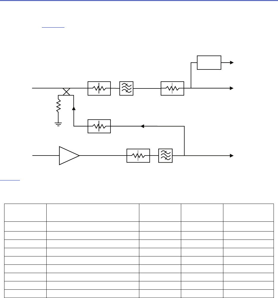
Theschematicin
Figure3
showstheblocksintheBIUforoneofthechannelsandhowthesignaldetectorforthe
downlinklevelalarmsareconnected.
Figure 3 Schematic of One BIU RF path
Table2
listsstandardcellularBIU’s.Otherconfigurationsareavailableuponrequestaswellasunitswithout
internalduplexfiltering.
Table 2 Standard variants of the BIU
Part No Configuration UL
MHz
DL
MHz
BTS
I/F
DBI303 2xTETRA390MHz†
†. Severaloptionsexistsfor5MHzstandardbandsforTETRA
380‐385 390‐395 Duplex
DBI307 2x700MHZABC‐band 698‐716 728‐746 Duplex
DBI308S 2xSMR800 806‐825 851‐870 Duplex
DBI308 2x850MHz 824‐849 869‐894 Duplex
DBI309 2x900MHz 880‐915 925‐960 Duplex
DBI318 2x1800MHz 1710‐1785 1805‐1880 Duplex
DBI319 2x1900MHz 1850‐1910 1930‐1990 Duplex
DBI320 2xUMTS2100MHz 1920‐1980 2110‐2170 Duplex
DBI321 2xAWS2100MHz 1710‐1755 2110‐2155 Duplex

SystemDescription
8
Table 3 RF and electrical performance of the BIU
Parameter Value Unit
Downlinkattenuation Settable 10‐30±3dB
UplinkGainformodules<1000MHz Settable 10to20±3dB
UplinkGainformodules>1000MHz Settable ‐10to10±3dB
IM3performance >55 dB
Maxinputnon‐destructive >36 dBm
Highinputalarmthresholdlevel 33 dBm
Lowinputalarmthresholdlevel 10 dBm
Inputreturnloss >20 dB
ImpedanceforallRFports 50 Ω
Isolationbetweenports >60 dB
Powerconsumption <15 W
Temperaturerange 0‐45 °C
Table 4 BIU mechanical specifications
Parameter Value
BasestationRFports SMA,Female
Testportsuplink(ifpresent) SMA,Female
InterconnectingRFportstoPOI QMA,Female
Alarmconnector DB9,Female
Dimensions,RackUnit
Width 2U
Height 3U
BIU Indicator Operation
TheBIUhastwoLEDslocatedonthefrontpanel.OneisthepoweronLED(green)andtheotheristhealarmLED
(red).BothLEDsindicateanumberofstatesbydifferentflashingbehaviors.
InanerrorstatethewebinterfaceshouldbeusedtochecktheactualconditionoftheBIUbuttheLEDsonthefront
cangiveyouaquickindicationonthestateoftheunit.Itisalsousefulforlocatingthephysicalunitifyouhave
severalBIUsinstalledinthesamerack.
Table 5
State ON LED ALARM LED Note
Booting 2Hz Off Normalboot
Bootingstandalonemode 2Hz 2Hz Notattachedtorack
BootingreadofMACaddressfailed 2Hz On Error
Starting 0,1Hz90%0,1Hz90% Kernelstartup
Operation 0,5Hz10%Off Normaloperation
Operation 0,5Hz10%1Hz10% Minoralarmstate
Operation 0,5Hz10%2Hz25% Majoralarmstate
Operation 0,5Hz10%On Criticalalarmstate
Indicator behavior
FiberDistributedAntennaSystem(FiberDAS)
9
Figure 4 BIU Interfaces
! "
"
#
#
#
#
Item Description
ThisisRFpathwheretheradiobasestation(RBS)isconnected(SMA)tothe
BIU.Donotexceedthepowerratinginthedownlinkfortheport.
Thisisatestport(SMA)fortheuplink.ItshowstheuplinksignalintheDL/UL
BTSport‐6dB.ThisportisreplacedbytheULportonanon‐duplexedversion
oftheBIU.
Thesearetheoutputports(QMA)forthedownlinksignalsaftertheyhave
beentreatedintheBIUwithattenuatorsandfilters.
UplinksignalsareconnectedtotheBIUusingtheseports(QMA).TheBIUwill
amplifyand/orattenuatethesignalsasappropriate.
Usedforexternalalarmmonitoring(futureupgrade).
TheLEDsindicatevariousstates,see
Table5
.
DL/ULBTS1/2
TPUL1/
2
DLOUT1/2
ULIN1/
2
EXTERNALALARMS
ON/ALMLED
SystemDescription
10
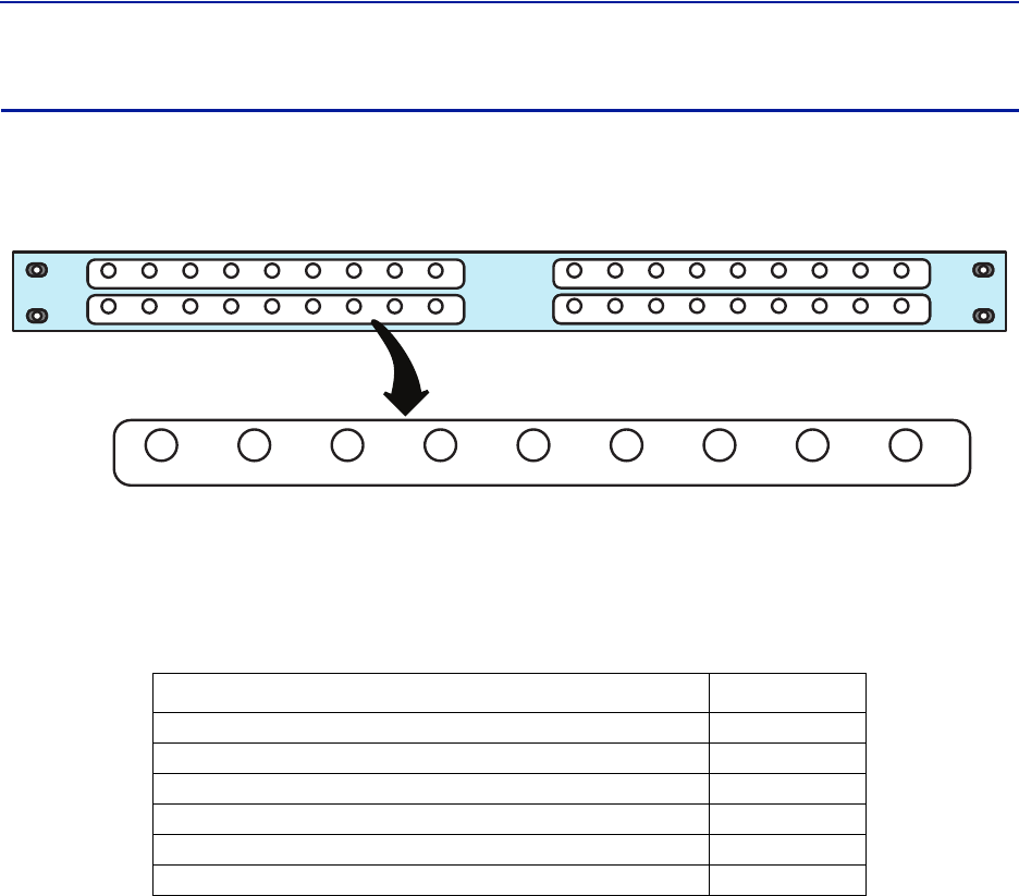
Point of Interconnect (POI)
ThePointofInterconnect(POI)contains41:8splittersandsomeattenuators.Thisisacouplingfieldusedtotie
togetherthesignalsbetweentheBIUsandtheFOIsinamultiplebandormultipleoperatorsystem.
Figure 5 Point of Interconnect (POI)
Eachofthe4fieldshasaCOMMONportandports1‐8.Ifusedasacombinerthenthesignalstocombineare
connectedtoports1‐8andthesumofthesignals(minusinsertionloss)isoutputontheCOMMONport.
Whenusedasasplitter,thecombinedsignalisinputontheCOMMONportandequalsignalsofthesamestrength
(minusinsertionloss)areoutputonports1‐8.
Table 6 POI Specifications
Parameter Value
InsertionlossCOMMONtoanyport1:8 35dB,Nominal
IM3performance >50dB
Returnlossperformance >20dB
Maximumsignalinputlevel 20dBm
Isolationbetweenportsinsamestrip >15dB
Isolationbetweenportsindifferentstrips >60dB
FiberDistributedAntennaSystem(FiberDAS)
11
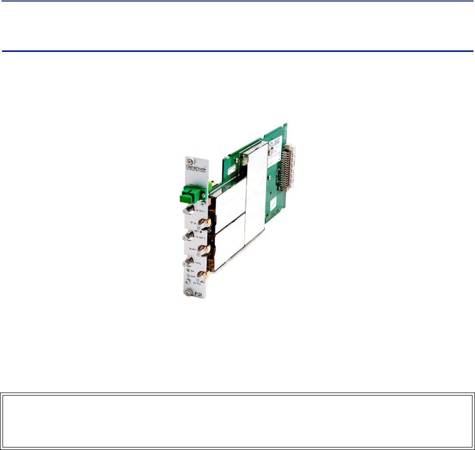
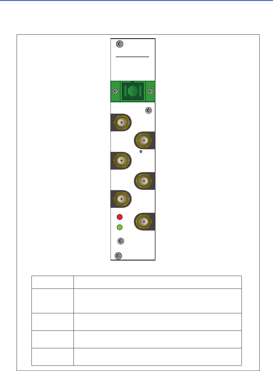
Fiber Optic Interface (FOI) unit
TheFOIconvertstheRFsignalsinthedownlinktofiber‐opticallaseroutputthatistransmittedonthefibertothe
remoteunit.ItalsoreceivesthelaserlighttransmittedbytheRemoteUnitandconvertsitbacktoRFsignalsthatare
thenroutedtothePOIandthentotheBIU.
Figure 6 Fiber Optic Interface (FOI) Unit
TheFOIisavailableineitherasingleheadfiberinterface(withWDM)configurationorwithadualheadfiber
interfacewithseparateRXandTXconnectors.
EachFOIcanserveupto4RemoteUnitsonasinglefiber.ThedrawbackisthattheRemoteUnitsmusthavedifferent
opticalwavelengthsintheuplinktoavoidinterference.Theycanhoweversharethesameopticalwavelengthinthe
downlink.
Functional description
TheFOIhasanominalgainof35dBandthelasertransmittershouldseeamaximumcompositeinputpowerofca
0dBm.Thismeansthatfor0dBattenuationintheDLamaximuminputof‐35dBmcompositepoweris
recommended(whenattenuatorsaresetto0dBm).IftheDLattenuatorissettoahighervaluethemaximum
recommendedinputisadjustedaccordingly.
Theoutputpowerofthelaseriscalibratedto3000µW.Thiscanbeusedtocheckthelossoverfiberintheremote
becausetheremotereportsthereceivedopticallevels.ThelossmaybedifferentintheULcomparedtotheDL
becauseofdifferentwavelengthsonthelaser.
TheFOIispoweredfromtheMFUbackplaneandcommunicateswithEthernetwiththeothermodulesintheMaster
Unit.
TheunitcontainsseveraladjustableattenuatorswhichareusedtocompensateforlossbeforetheFOI(e.g.inthe
POI)andforlossonthefiberintheuplink.TherearetwosetsofRFportsontheFOIthatcanbeusedtoconnect
signalsfromtwodifferentstripsinthePOI.
TheEthernetcommunicationbetweentheMasterUnitandtheRemoteUnittakesplaceontwosub‐carriersinthe
FOIwheretheEthernetsignalsaresuperimposedontheRFsignals.
WARNING
Avoidlookingintoconnectedfibersandreceptacles.
ThelaserusedinthissystemisaClass3blaserthatproducesinvisibleinfra‐redcoherentlight.Notsafetoview
withopticalinstruments.Alwaysputtheprotectioncapsonunusedfibersandreceptacles.
SystemDescription
12
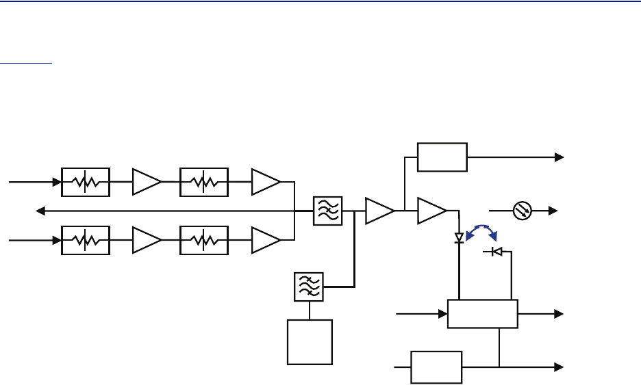
Figure7
isablockdiagramshowingthedownlinkpathintheFOIandhowthetestportisconnected.Asyoucan
seetherearetwoattenuatorsthatcanbesetintheDLpath,thisallowsforbalancingtheinputsignalsfromtwo
differentsignalsourcessothattheycansharethedynamicsofthelaserproperly.
Figure 7
FOI Block Diagram
TheRFdrivelevelsaremeasuredandaccessibleinthewebinterfacesothattheycanbechecked.Inthefuture
alarmlevelsmaybeaddedtothesetestpoints.
ThisinterfaceisdesignedtoworkwithSC‐APCconnectors(7°angledphysicalconnector)andsinglemodefibers
only.Allconnectorsbetweenthemasterunitandtheremoteunitshouldbeofangledtype,otherwiseproblems
withreflectionswillarisewhichmaycausesevereproblemsinthesystem.
Singlemodefiber
Angledconnectors
Opticalloss<15dB
FiberDistributedAntennaSystem(FiberDAS)
13
Figure 8 FOI
!
"
"
Interfaces
Item Description
Thisisthereceptaclefortheopticalfiber.Theillustrationshowsthe
modulewithbuiltinWDM(combinedRX/TX).Theversionwithout
WDMhastwoconnectorsoneforTXandoneforRX.
ThesearetheRFportsthatnormallyarepatchedtothePOIfor
interconnectingandthenontotheBIU.
ThesearetheRFconnectorswherethesignalintheDLfromthePOI
ispatchedintotheFOIforconversiontolaserlight.
Thesearetestportsthatcanbeusedtocheckthesignallevelsor
noiseinthesystem.
OPTOIN/OUT
ULOUT1/2
DLIN1/
2
TPUL/DL

SystemDescription
14
TherearealsotwoLEDsontheunitwhichcanbeusedtocheckthestatusaccordingtothefollowingtable:
Table 7
State ON LED ALARM LED Note
Booting 2Hz Off Normalboot
Bootingstandalonemode 2Hz 2Hz Notattachedtorack
BootingreadofMACaddressfailed 2Hz On Error
Starting 0,1Hz90%0,1Hz90% Kernelstartup
Operation 0,5Hz10%Off Normaloperation
Operation 0,5Hz10%1Hz10% Minoralarmstate
Operation 0,5Hz10%2Hz25% Majoralarmstate
Operation 0,5Hz10%On Criticalalarmstate
FOI LED indicators
Table 8 FOI Specifications
Parameter Value
MaximumfiberlossfromMUtoRU,Optical, 15dBo
Opticaloutputpower,Calibrated 3000µW
MaximumnumberofRUsupportedonsinglefiber 4
InputRFpowerrecommended,Composite ‐50to‐35dBm†
†. Dependsonattenuatorsettings.For0dBattenuationcompositelevelshouldbe< ‐35dBm.
Powerconsumption <15W
OperationalTemperaturerange 0to45°C
Dimensions
Width 1U
Height 3U
Opticalconnectortype SC‐APC
RFconnectortype QMAFemale
Table 9 FOI variants
Parameter Wavelength
DOI301 1310nm RxandTxseparate
DOI302(WDM) 1310nm RxandTxonsamefiber
DOI308x SeparateRxandTxvariouswavelengthsavailable†
†. TheDOI308versioncanbeorderedwithvariouswavelengths.Theactualwavelengthsthatare
possibleareavailableuponrequesttoinfo@deltanode.com.
FiberDistributedAntennaSystem(FiberDAS)
15
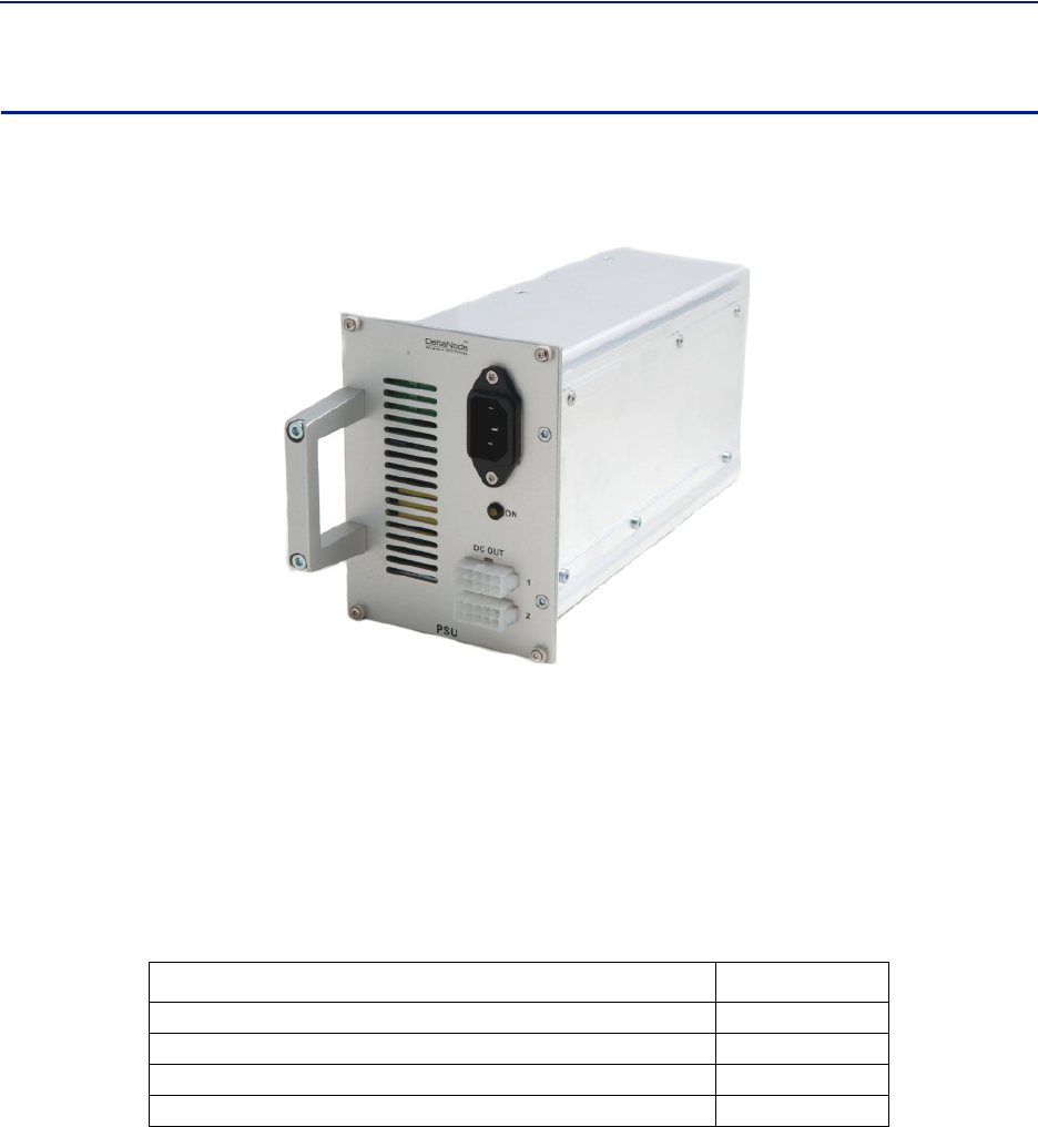
PSU – the rack power supply
Thepowersupplyunitcanhandleuptoonefullshelfofactiveunits,suchasBIUorFOI.Ifyoursystemconsistsof
morethanoneshelf,aPSUisaddedforeachshelf.
Figure 9 PSU
Functional description
ThePowerSupplyUnitisnormallydeliveredasa240VACversionforEuropeand115VACversionforUSorother
countriesusingthisvoltage.A‐48VDCtelecomversionisavailable.
Allconnectorsareonthefrontsideofthepowersupply.ThepictureshowsthePSUequippedwithEuropeanpower
inlet.Outputaretwo10pinMolexconnectorsthatwillbeconnectedtotheshelfthePSUissupplyingpowerto.One
connectorshouldalwaysbeconnectedtotheshelfthatthePSUislocatedin(fordrivingthefans).
Oneshelfcanhandleupto4powersupplies.EachshelfcanhavetwoPSU’sconnectedtoitforredundancy.
Table 10
Parameter Value
Inputpowervoltage,Mains 86‐264VAC
Inputpowerfrequency,Mains 50/60Hz
Operatingtemperature 0‐45°C
Powerrating 240W
PSU Specifications
SystemDescription
16
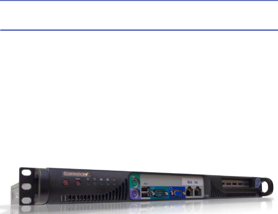
Base Station Master unit Gateway (BGW)
BaseStationMasterunitGateway(BGW)isaself‐poweredLinuxbasedserver.ItassignsIPaddressestoallthe
modulesinthesystem,includingtheRemoteUnitsaswellastheircomponents.ModulesinaMasterUnitwill
inherittheirIPaddressesviaDHCPleasesandbywayofinheringtheMACaddressesfromthebackplanewecan
ensurethatanewmoduleinsertedintherackreceivesthesameaddressastheoneitisreplacing,withoutanyneed
ofmanualconfiguration.
FeaturesoftheBGW:
Webinterfaceconfiguration
Automaticdetectionofmodules
AutomaticdetectionofRemoteUnits
Canhandlelargesystems
Functionsforstatistics
NorthboundcommunicationtoCGW
Includesfirewalltoprotectlocalnet
IstheportaltoyourMasterUnit
User‐providedcertificatebasedsecurityviaHTTPS
Figure 10 Base station master unit gateway
IftheBGWisreplacedtheRemoteUnitsmaynotshowupimmediately.Thisisduetotheleasetimeontheaddress
theyhave.Eventuallytheywillrequestanewaddressandwhenthisisdonetheywillshowup.
TheBGWistheunitresponsibleforalarmhandlingandremoteforwardofalarmseitherbySMTPmailforwardingor
bySNMPtraps.AMIBfileforyourSNMPsystemisavailablefromDeltaNodeuponrequestaswellasdocumentation
regardingSNMP.
TheBGWcanalsolaunchVPNtunnelstoaremotesupervisioncentercalledtheCentralGateway(CGW).Thismakes
itpossibletomanagemultiplesystemsfromasingleplace.TheCGWwillbedescribedlaterinthismanual.
TheBGWhastwoEthernetports.OneisconnectedtotheinternalnetworkintheMasterUnittoprovidethelocal
networkforallthemodules,theRemoteUnitsandeverythingelse.Italsoprovides,viathebuilt‐inswitchinthe
MasterUnit,awayoflocallyconfiguringthenetwork.Itprovidesthewebinterfaceforallthesettingsofthesystem
aswellasmanyotherfunctions.Secondlythereisa“northbound”EthernetportthatallowstheBGWtoconnectto
theInternet,oraWAN/MANtypeoflargernetwork.Thismeansthatthesystemcanbemonitoredandmanaged
remotely.
AVirtualPrivateNetwork(VPN)tunnelcanbesetupfromtheBGWtoacentrallocationusingaCGW.TheCGWcan
handlealargenumberofsuchtunnels,providingacentralpointforsupervisingalltheinstallationsandcollecting
alarmsandstatisticsfromallthesystemsaswellascentralizedalarmmanagement.TheBGWcanactuallysetupa
secondtunnel,whichissometimesdonetotheDeltaNodemanagementcenterwherewecanhelpwith
managementandsupervision.Thisisaservicethatweprovideifneeded.

FiberDistributedAntennaSystem(FiberDAS)
17
Table 11
Parameter Value
Inputpowervoltage,Mains 100‐240VAC
Inputpowerfrequency,Mains 50/60Hz
Operatingtemperature 10‐30°C
Powerrating,Typical <100W
Height 1U
Width 19In.
Depth 360mm
Weight <5kg
BGW specifications
ABGWcanalsobesetupinfactoryforaspecialneed,itwillthenbedeliveredtogetherwitharestoreimagethat
allowsthecustomertorestoreitquicklyincaseofahardwarefailure.
RGW – the compact remote gateway
TheRGWisasmallunitsimilartotheBGWbutintendedforsmallsystemswherethereisalownumberofremotes
orwherethereisnohead‐endandthereforetheRGWhasaformfactorthatallowsittobemountedinsidea
repeatercasing.
Thiscanbeusedtorunupto4RemoteUnitsfromasingleRepeateronasingleFiber.TheRGWhasthecapabilityto
connectNorthboundtoaCentralGateway(CGW)justliketheBGWdoesanditcanalsoforwardalarmsthrougha
VPNtunneltoaCGW.
ThememorycapacityandfeaturesarereducedcomparedtotheBGWbutforasmallsystemwithasinglefiberthis
maybeanoptiontouse.
TheRGWcanbeequippedwithamodemtoallowaccesstoasysteminaremotelocationwherethereisno
Ethernet.Themodemisusuallya3GmodemwhichenablestheRGWtosetupatunneltoaCentralGatewayunit
(CGW)enablingsupervision,monitoringandcontrolofthesystem
SystemDescription
18
Remote Unit (RU)
Therearemanydifferentkindsofremoteunitswithawiderangeofgainandoutputpowertocatertomany
differentneeds.Alowandmediumpowerunitcanhouseupto4differentfrequencybandsinoneunit,thehigh
powerversionscanhandleupto2differentbandsinonesingleunit.
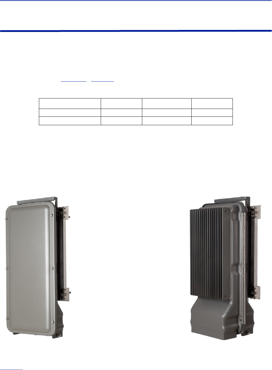
Chassis types
Remoteunits(RUs)areavailableinmainlytwodifferentchassis,asinglecompactchassisfor1‐2bandsandadual
chassisforupto4bands(
Figure11
).
Table12
showshowtheycanbeconfigured:
Table 12
Chassis type Low Medium High
Singlechassis 1‐2 1‐2 1
Dualchassis 3‐4 3‐4 2
Chassis types
Itisalsopossibletohavecombinationsoftheabove.Forexampleitispossibletobuildadualchassiswith2medium
powerbandsand1highpowerbandinthesameremote.Eachsideofadualchassisisvirtuallyidenticaltoasingle
chassisremoteunit.Thisensuresunparalleledflexibilitywhenbuildingmultipleoperator/multiplebandsolutions.
Adualchassismayhave1‐2opticalremoteunits(FOR).Thiswaytheycanbefedfromdifferentdirectionsfor
redundancy.
Figure 11
Single Chassis
Remote Unit
Dual Chassis
Remote Unit
Remote Unit Chassis Types
BecauseofthelargerpoweramplifiersusedforhighpowerRU’stheneedformorecoolingandroomallowsonly2
bandsinthesamedoublechassis.Remotescanalsobedaisy‐chainedbywayofRFcables,meaninguptotwo
chassiscansharethesamefiber‐opticalinterfaceprovidingupto8bandsinasinglelocation.
Table13
containsalistofthemostcommonremoteunitsthatareusedwiththeDeltaNodeFiber‐DASsystem.
Variantsareavailableuponrequest.

FiberDistributedAntennaSystem(FiberDAS)
19
CommonforallRemoteUnitsistheirexcellentnoisefigure,contributingtoanoverallnoisefigureforthewhole
systemfromremotetohead‐endintothebasestationof<3dBfortheRFlink.
BothchassiscomplywithIP65protectionforuseinanyenvironment.Thecoatingisadurablecoatingwhichaidsthe
convectioncooling.NofansareusedfortheRemoteUnits.Bothchassisareavailablewitheitherwallorpole
mountingkits,asrequested.
Note: RemoteUnit’sarecompletelyassembledatourfactory,nointegrationoftheRemoteUnit’s
componentsisrequired.
Table 13
Product code Pout (ETSI)†
†. Actualpowerdeterminedbyfrequencybandandspectrumdemands.
Pout (FCC) Bands
DDRmediumpower) 26‐30 361‐4
DDS(Highpowerquadband) 30‐41 41 1‐4
DDH(highpower) 32‐43 43 1‐2
DDH2(Dualamplifiers) N/A 46 1
Remote comparison table
DDR
DeltaNode’sDistributedRadioheadisahighperformingwidebandradioheadequippedwithalinearpower
amplifiersupportingallmodulations.Thelightweight,convectioncooledIP65chassissecurestheperformancein
almostanyenvironment.
ETSI standard
Table 14 General Specifications
NoiseFigure Typical 3dB
Delayexcludingopticalfiber <0,5 µs
PowerSupply Mains 85–264 VACorVDC
OperatingTemperature ‐25‐+55
Casing IP65
Table 15 Optical Specifications
RFFrequencyrange 88–2200MHz
Flatness +‐3dB
Opticaloutputpower Nominal 3mW
DFBLaseroutputWavelength1270‐1610 nm
Opticalreturnloss <‐40dB
Opticalisolator min 30dB
Side‐modesuppressionratio min 30dB
Maximumopticalinputpower nondestructive 10mW

SystemDescription
20
Table 16 Specifications DDR100 (Single Band) & DDR200 (Dual band)
PowerConsumption,max DDR100(200) 90(180) W
Dimensions WxDxH300x130x700mm
Weight <12 Kg
Table 17 Specifications DDR300(Triple Band) & DDR400(Quad Band)
PowerConsumption,max DDR300(400) 270(360) W
Dimensions WxDxH300x220x700mm
Weight <24 Kg
Table 18 Available Products, European Cellular
System ULFrequency
MHz
DLFrequency
MHz
Pout(DL)
dBm/c,
1Carrier
Pout(DL)
dBm/c,
2Carriers
Standard
TETRA,PublicSafety 380‐385 390‐395 26 23 ETSI
TETRA,Commercial 410‐415 420‐425 26 23 ETSI
TETRA,Commercial 415‐420 425‐430 26 23 ETSI
CDMA450 453‐457,5 463‐467,5 33 28 FCC
GSM‐R876‐880921‐925 26 23 ETSI
EGSM900 880‐915925‐960 26 23 ETSI
GSM1800 1710‐17851805‐1880 28 25 ETSI
UMTS 1920‐1980 2110‐2170 30 25 3GPP
FCC standard
DeltaNode'sDistributedRadioheadisahighperformingwidebandradioheadequippedwithalinearpower
amplifiersupportingallmodulations.Thelightweight,convectioncooledIP65chassissecurestheperformancein
almostanyenvironment.
Table 19 General Specifications
NoiseFigure Typical 3dB
Delayexcludingopticalfiber <0,5 µs
PowerSupply Mains 85–264 VACorVDC
OperatingTemperature ‐25‐+55
Casing IP65
Table 20 Optical Specifications
RFFrequencyrange 88–2200MHz
Flatness +‐3dB
Opticaloutputpower Nominal 3mW
DFBLaseroutputWavelength1270‐1610 nm
Opticalreturnloss <‐40dB
Opticalisolator min 30dB
Side‐modesuppressionratio min 30dB
Maximumopticalinputpower nondestructive 10mW

FiberDistributedAntennaSystem(FiberDAS)
21
Table 21 Specifications DDR100 (Single Band) & DDR200 (Dual band)
PowerConsumption,max DDR100(200) 90(180) W
Dimensions WxDxH300x130x700mm
Weight <12 Kg
Table 22 Specifications DDR300 (Triple Band) & DDR400 (Quad Band)
PowerConsumption,max DDR300(400) 270(360) W
Dimensions WxDxH300x220x700mm
Weight <24 Kg
Table 23 Available Products, American Cellular
System ULFrequencyMHz DLFrequencyMHz
Pout,DL,
dBm
(Composite)
Standard
LTELB 698‐716728‐746 33 FCC
LTEUB 746‐776* 776–806†
†. Sub‐bandsavailable
33 FCC
iDEN 806‐824 851‐869 33 FCC
Cellular 824‐849 869‐894 33 FCC
PCS1900 1850‐1915 1930‐1995 33 FCC
AWS 1710‐1755 2110‐2155 33 FCC
Table 24 Available Products, American Public Safety
System
UL
Frequency
MHz
DL
Frequency
MHz
Pout,DL,
dBm
(Composite)
Nominal
Bandwidth
MHz
Nominal
Passband
Gain
dB
Input/Output
Impedance
Ohms
Standard
VHF 150‐174150‐174 33 24(FCC);36(IC)†
†. 2MHzwithrequiredexternalduplexers
70 50 FCC
UHF 450‐512450‐512 33 62††
††.3MHztor1.5MHzwithrequiredexternalduplexers
70 50 FCC
700 793‐805763‐775 33 12 70 50 FCC
800 806‐824 851‐869 33 18 70 50 FCC
Class B Industrial Booster — ThisequipmentisaClassBIndustrialBoosterandisrestrictedtoinstallationas
anIn‐buildingDistributedAntennaSystem(DAS).
RF Exposure — Theequipmentoperatinginthe800MHzpublicsafetybandandtheUHFpublicsafetyband
complieswiththeFCCRFradiationexposurelimitssetforthforanuncontrolledenvironment.Thisequipment
shouldbeinstalledandoperatedwithaminimumdistanceof20centimetersbetweentheradiatorandyourbody.
Theequipmentoperatinginthe700MHzpublicsafetybandrequireaseparationdistanceofatleast36.2cm.This
distancemustbemaintainedbetweentheuserandantennawhentheproductisusedwitha5.5dBiantenna.
TheequipmentoperatingintheVHFpublicsafetybandrequireaseparationdistanceofatleast69.1cm.This
distancemustbemaintainedbetweentheuserandantennawhentheproductisusedwitha10.5dBiantenna.
Ifsystemwilloperateonmultiplebands,theseparationdistancerequiredshallbeequalto,orgreaterthan,the
bandwiththelargestseparationdistance.

SystemDescription
22
DDS
DeltaNode'sDDSseriesdistributedhighpowerradioheadisahighperformingwidebandradioheadequippedwith
aPreDistortionpoweramplifierthatsupportsallmodulations.Thelightweight,convectioncooledIP65chassis
securestheperformanceinalmostanyenvironment.
FCC Standard
Table 25 GENERAL SPECIFICATIONS
NoiseFigure Typical 3dB
Delayexcludingopticalfiber <0,5 µs
InstantaneousBandWidth Max 15 MHz
PowerSupply Mains 85–264 VACorVDC
OperatingTemperature ‐25‐+55
Casing IP65
Table 26 OPTICAL SPECIFICATIONS
RFFrequencyrange 88–2200MHz
Flatness +‐3dB
Opticaloutputpower Nominal 3mW
DFBLaseroutputWavelength1270‐1610 nm
Opticalreturnloss <‐40dB
Opticalisolator min 30dB
Side‐modesuppressionratio min 30dB
Maximumopticalinputpower nondestructive 10mW
Table 27 SPECIFICATIONS DDS100 (Single Band) & DDS200 (Dual band)
PowerConsumption,max DDS100/200 90(180) W
Dimensions WxDxH300x130x700 mm
Weight <12 Kg
Table 28 SPECIFICATIONS DDS300 (Triple Band) & DDS400(Quad Band)
PowerConsumption,max DDS300/400 270(360) W
Dimensions WxDxH300x220x700mm
Weight <24 Kg
Table 29 AVAILABLE PRODUCTS, AMERICAN CELLULAR
System ULFrequencyMHz DLFrequencyMHz DownlinkPowerRMS Standard
LTELB 698‐716728‐746 41 FCC
LTEUB 746‐776†
†. Sub‐bandsavailable
776–806†41 FCC
iDEN 806‐824 851‐869 41 FCC
Cellular 824‐849 869‐894 41 FCC
PCS1900 1850‐1915 1930‐1995 41 FCC
AWS 1710‐1755 2110‐2155 41 FCC

FiberDistributedAntennaSystem(FiberDAS)
23
DDH
DeltaNode'sDistributedHighpowerradioheadisahighperformingwidebandradioheadequippedwithafeed
forwardmulticarrierpoweramplifierthatsupportsallmodulations.Thelightweight,convectioncooledIP65
chassissecurestheperformanceinalmostanyenvironment.
ETSI standard
Table 30 GENERAL SPECIFICATIONS
NoiseFigure Typical 3dB
Delayexcludingopticalfiber <0,5 µs
PowerSupply Mains 85–264 VACorVDC
OperatingTemperature ‐25‐+55
Casing IP65
Table 31 OPTICAL SPECIFICATIONS
RFFrequencyrange 88–2700MHz
Flatness +‐3dB
Opticaloutputpower Nominal 3mW
DFBLaseroutputWavelength1270‐1610 nm
Opticalreturnloss <‐40dB
Opticalisolator min 30dB
Side‐modesuppressionratio min 30dB
Maximumopticalinputpower nondestructive 10mW
Table 32 SPECIFICATIONS DDH100(Single Band)
PowerConsumption Typical 210 W
Dimensions WxDxH300x130x700mm
Weight <14 Kg
Table 33 SPECIFICATIONS DDH200(Dual Band)
PowerConsumption Typical 420 W
Dimensions WxDxH300x220x700mm
Weight <28 Kg
Table 34 AVAILABLE PRODUCTS, EUROPEAN CELLULAR
System
Numberofcarriers
24816
Composite
Power
Powerper
carrier
Composite
Power
Powerper
carrier
Composite
Power
Powerper
carrier
Composite
Power
Powerper
carrier
TETRA 32 29 33 27 33 24
EGSM900 40 34 40 34 40 31 40 28
GSM1800 40 37 40 34 40 31 40 28
UMTS 43 40 43 37 43 34 43 31
2600 43 40 43 37

SystemDescription
24
FCC standards
Table 35 GENERAL SPECIFICATIONS
NoiseFigure Typical 3dB
Delayexcludingopticalfiber <0,5 µs
PowerSupply Mains 85–264 VACorVDC
OperatingTemperature ‐25‐+55
Casing IP65
Table 36 OPTICAL SPECIFICATIONS
RFFrequencyrange 88–2200MHz
Flatness +‐3dB
Opticaloutputpower Nominal 3mW
DFBLaseroutputWavelength1270‐1610 nm
Opticalreturnloss <‐40dB
Opticalisolator Min 30dB
Side‐modesuppressionratio Min 30dB
Maximumopticalinputpower nondestructive 10mW
Table 37 SPECIFICATIONS DDH100(Single Band)
PowerConsumption Typical 210 W
Dimensions WxDxH300x130x700mm
Weight <14 Kg
Table 38 SPECIFICATIONS DDH200(Dual Band)
PowerConsumption Typical 420 W
Dimensions WxDxH300x220x700mm
Weight <28 Kg
Table 39 AVAILABLE PRODUCTS, AMERICAN CELLULAR
System ULFrequencyMHz DLFrequencyMHz Pout,DL,
dBm(RMS) Standard
LTELB 698‐716728‐746 43 FCC
LTEUB 746‐776†
†. Sub‐bandsavailable
776–806* 43 FCC
iDEN 806‐824 851‐869 40 FCC
Cellular 824‐849 869‐894 43 FCC
PCS1900 1850‐1915 1930‐1995 43 FCC
AWS 1710‐1755 2110‐2155 43 FCC
Note: Allspecificationssubjecttochangewithoutnotice.
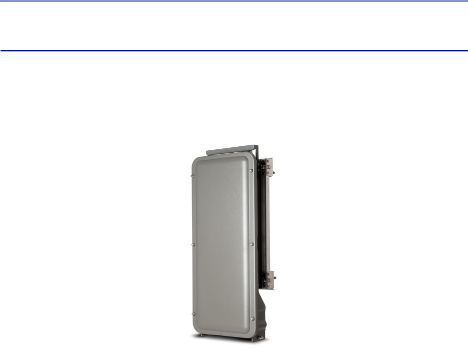
FiberDistributedAntennaSystem(FiberDAS)
25
DMU – Remote head end
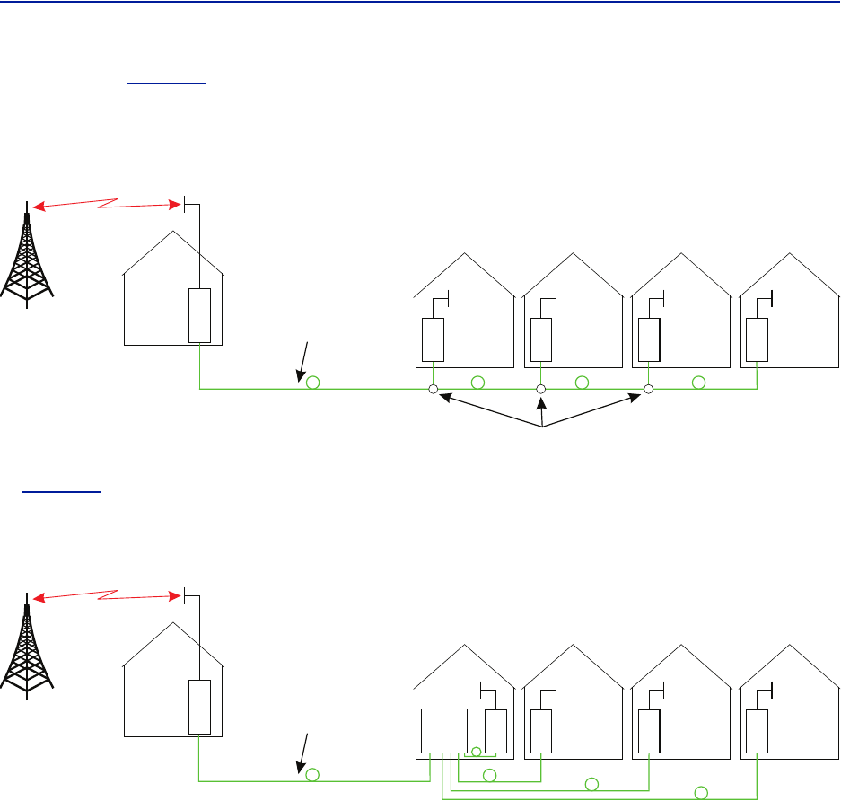
DeltaNodeDMU100seriesisapickuprepeaterthatcanprovidethesignalsoverfibertoaMasterUnitordirectlyto
upto4RemoteUnits.WhentheDMUisusedtotransmitthesignalstoaMasterUnit,theordinaryBGWisusedto
controlthesystem,butincasetheMasterUnitisnotneededanditconnectsdirectlytoupto4RemoteUnitsthe
DMUcanbeequippedwiththecompactgateway,RGW,toprovideforthesettingsandalarmhandlingfortheentire
system.
Figure 12 DMU – Remote head end
RemotecommunicationcanbedoneeitheroverEthernetifthatexistsinthelocation,ortheunitcanbeequipped
withamodemthatallowsittosetupatunneltoaCentralGatewayCGWwhereitcanbecontrolledremotely.The
modemisnormallyastandard3Gmodembutotheroptionsmaybepossibleifneeded.
ItispossibletobuildtheDMUwithmorethanoneband.However,dependingonthetypesofbandsandthe
necessaryduplexersitmayneedtobeverifiedwithDeltaNodethatyourcombinationofbandsarepossibleifthe
RGWistobeincluded.
ThechassisisthesameasfortheDeltaNodeRemoteUnits(singlechassis)andcanhandleasingleband.
SystemDescription
26
Intheexamplein
Figure13
,theDMUisusedtopickupthesignalataremotelocationandthenitistransmittedon
thefibertofourdifferentlocationsthatneedcoverage.TheRUcanbeconnectedtocoaxialspreadingnetworksif
needed.
Figure 13
DMU Feeding Remote Units
In
Figure14
,theDMUisfeedingaMasterUnit(BMU)whichinturnfeedstheRemoteUnits(RU).Thisisafarmore
flexiblesolutionandshouldbepreferredwhenitispossible.
Figure 14
DMU Feeding BMU
TheDMUisusuallynotequippedwithapowerfulPowerAmplifier(PA)intheuplinkbecausetheideaofusingitisto
placetherepeaterwherethereisagoodsignal.Thepowerlevelmatchesthatofamobilephone.

27
Chapter 3 System design
Fiber‐DASisawayofdistributingradiosignalsfromabasestationtoaremotelylocatedantennawherethecoaxial
cablelosseswouldbetoohighoritisimpracticaltoinstallcoaxialcables.Fiber‐DAScanbeusedindoorstocover
largebuildingswhereoutsidepenetrationofradiosignalsisnotsufficient,itcanbeusedtocoverstructuressuchas
tunnelsforrail,orroads,airports,metrolinesandmanyotherplaces.
Thischapterprovidesthebasicsofsystemdesignandavoidingcommonpitfalls.Allfiber‐DASsharesomecommon
propertiesastheyareanextensionofanexistingsignalintoanareawherethereislittleornocoverage.
The Basics
Thereissomebasicknowledgeyoushouldbefamiliarwithwhendesigningasystem.Inthissectionwewilldiscuss
themostimportantelementsofdesigntohelpyoudesignyoursystem.
Alinkbudgetisawayofcalculatingtherequiredsignallevelsforthebasestationandthemobilestationand
matchingthisagainstyoursystemdesign,thelossesinthecables,theantennafactorsandothersuchparametersgo
intoalinkbudget.
WhenyouhavedonearoughlinkbudgetyoushouldusetheDAScalculatorandcalculatethesettingsofeachuplink
anddownlinkinthesystem.
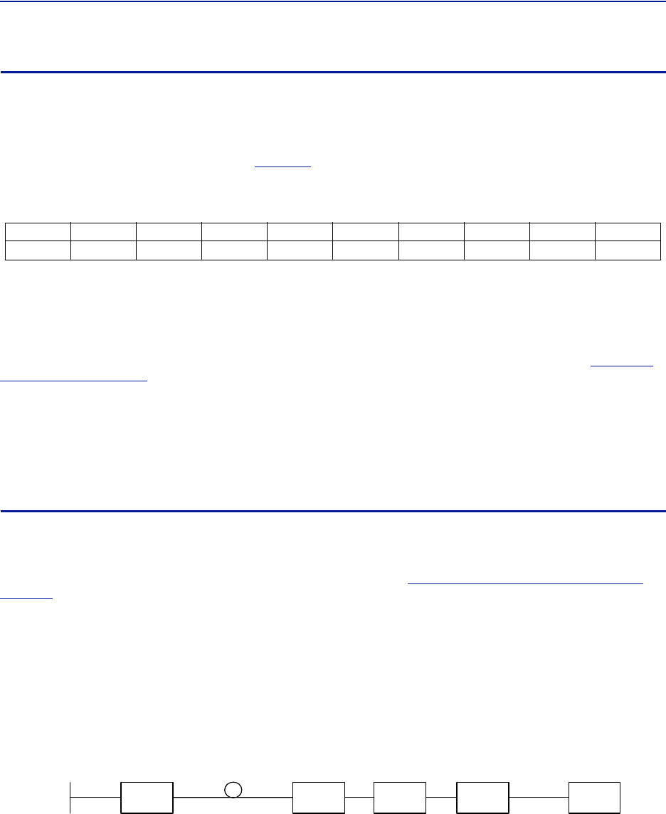
Example:Youhaveasystemwith3remoteunitsandtheyarealldualband850/1900forCDMAandGSM.Your
systemhas6uplinksand6downlinkswherethesignalmayproceedfromantennatobasestationorviceversa,in
unitonethereisone850RFstripandone1900RFstripformingtwoRFchainswithuplinksanddownlinks.
TheDAScalculatormayyieldadifferentnoisefigurefromtheoneyouinitiallyassumedwhenyoudidyourlink
budget.Thisisfine,youmayinsertthenewnoisefigureinyourlinkbudgetandobservetheresult.
Whenyouhavedoneyourcalculationsyoualreadyknowthesettingsofthesysteminprincipleandyoucannow
commissionit.UsingthesettingsfromtheDAScalculatorasabasisyoucanconnecttothesystemandsetitupone
unitatatime,moreaboutthatin
Chapter5"Commissioning"onpage40
.
Link Budgets
Thestartingpointistocreateaviablelinkbudgetforyoursystem.Aslinkbudgetsarecalculateddifferentfor
differentsystemsyoumaywanttotakesometimeandstudytypicallinkbudgetcalculationsforthetypeofservices
youareusing.
Youdonotneedtocreatelinkbudgetsforallofyourremotesandallfrequencybands.Doitfortheworstcaseonly
foreachservice,thatshouldbeenough.Thisisthenormalprocedureanditisusuallynotdifficulttofindtheworst
casescenario.Lookforthehighestlossbetweenthebasestationandtheantenna,includingthefiberlossbetween
MasterUnitandRemoteUnitandanysplitlossaftertheRemoteUnituntilyougettothelastantenna.
Ifyouareusingradiatingcables,thencalculatewiththelossoverthemaximumlengthofradiatingcableyouneed
tosupportandfindtheRemoteUnitthathasthehighesttotallossfromtheUserEquipment(mobilestation)tothe
BaseStationend.
Systemdesign
28
Downlink
Forthedownlinkyoucanusuallyjustusetheoutputpoweroftheremoteunitandthencalculateyourlinkbudget.
Rememberthatifyouhaveseveralcarriers,youneedtocalculateyourlinkbudgetwiththisinaccount.Foreach
newcarrieryouadd,thepowerpercarriergoesdownasthepowerontheRemoteUnitisdividedontoallthe
(active)downlinkcarriers.
Tocalculatethe“percarrier”outputpower,
Table40
containsalistofmodifiersthatareappliedtotheoutput
poweroftheremoteunit.
Table 40 Per carrier loss
Asyoucanseethereisacorrelationthatwheneverthenumberofcarriersdoublethepercarrierpowerislowered
withanother3dB.Thustheformulaforanynumberofcarrierswillbe:
PCarrier PComposite 10 10logNCarriers
–=
Theoutputpowerforeachtypeofremoteunitandfrequencybandcanbefoundinthedatasheetsin
"Remote
Unit(RU)"onpage18
wheretherelevantparametersforeachremotesystemarediscussed.
Remembertousethepercarrierpowerinyourlinkbudgetandnotthecompositebecauseifasyoukeepadding
carrierstothesystemthepowerpercarrierwillbelower.Ifyouareplanningonaddingadditionalcarriersinthe
futureyoushouldplanyoursystemforthemaximumforeseeablenumberofcarriers.
Followingisanexampleofalinkbudget.ThislinkbudgetisalsoincludedintheDASCalculatorpackage.Ifyoudo
nothavethispackagecontactDeltaNodeSolutionstoreceiveacopy.
Uplink
Uplinkcalculationsgenerallyrelyonhavingthenoisefigureathandbeforesothatthedesensitizationofthebase
stationcanbecalculated.Howeversincethenoisefigureisdependentonthelinkbudget,weshouldbeableto
calculateacrudelinkbudgetatfirst,getourgainstraightandthenwhenwearedoneweshouldbeabletocalculate
thepropernoiseloadusingtheDASCalculatorTool(willbehandledin
Chapter6"RFCommissioning"on
page41
).Thereforewewillassumeastandardnoisefigurefornow,properlyadjustedtheDeltaNodeFiber‐DAS
solutionhasaNFoflessthan3dBperuplink.
AreasonableassumptionfortheNFisaround3dB,ifweshouldgetabetterorworseNFlaterwhentheDAS
Calculatorisemployedwewilljustgobackandcorrectthelinkbudgetsforthis.
SystemUplinkNetGain
ThenetgainisthetotalgainintheuplinkfromtheRemoteUnitporttotheinputportonthebasestation.Thischain
lookssomethinglikethis:
Figure 15
Antenna
RU
RemoteUnit Fiber
FOI
FOICard
POI
POIunit
BIU
BIU
BTS
BaseStation
50dB ‐40dB 20dB ‐35dB 7dB
‐80dBm ‐30dBm ‐70dBm ‐50dBm ‐85dBm ‐78dBm
‐2dB
‐80dBm
Uplink Net Gain
12345678910
0 -3.0 -4.8 -6.0 -7.0 -7.8 -8.5 -9.0 -9.5 -10.0

FiberDistributedAntennaSystem(FiberDAS)
29
Intheillustrationin
Figure15onpage28
thereisaninputsignaltotheremoteof‐80dBm.Theneachstepofthe
chainhasgainorattenuationasshown,thefiberlossisintotal40dB,theFOIissetto20dBgain,thelossthrough
thePOIis35dB,theBIUissetto7dBgainandthelossonthejumperbetweentheMasterUnitandtheRadioBase
Stationis2dB.
ThismeansthatthesignallevelenteredintotheRemoteUnitisseenbythebasestation.Thisisconsideredan
optimalpointsettingfortheuplinkwhenitcomestosignallevel.Ifthenetgainintheuplinkispositive,wealsoput
noiseontothebasestationandwilldesensitizeitsreceiver.Thismaynotbeaproblem,iftheBaseStationis
dedicatedtoonlytheFiber‐DASsystemthenapositivenetgainisnotaproblembecauseanydesensitizationcaused
byincreasedgainiscompensatedbyanequalincreaseintheusefulsignalslevel.ThusmaintainingthesameC/I.
HoweveriftheBaseStationisalsocoveringanoutdoorareaorhasotherantennasconnectedtothesamesector
thenapositivenetgainwillcauseadesensitizationofthereceiverfortheotherantennaandthisisgenerally
speakingabadthing.
Thesystemalsohasathermalnoiseloadthatitwillputonthebasestation,justlikeanantenna.Thenoisefigureof
thesystemcanbedeterminedbyusingtheFiber‐DAScalculatorexcelsheet.Thetotalnoiseisalsoanaccumulation
ofthenoiseposedbyeachchainandthenetgainofthesystem.
Ifwehaveasystemwith4equallysetupchains,andeachchainhasanoiseloadof3dBandthenetgainis0dB
thenthenoiseloadonthesystemwillbearound9dB.
IfwedecreasethenetgainintheuplinkwecanlowerthisnoiseasthesystemNFcanbeconstruedastheNF+Net
gainuplinktimesthenumberofequalchains.Sincethechainsarenotinfactequal,theywillhavedifferentNFand
differentgainslightlyitmaybeagoodideatocalculatethetotalnoiseload:
Table 41
Chain NF Gain N. Load Comment
Total Noise Load, Unadjusted
Byloweringthenetgainto‐5dBonallchainswegetthefollowing:
Table 42
Chain NF Gain N. Load Comment
Total Noise Load, Adjusted
ThisissimilartotheBTSownnoisefigurewhichgenerallyis2‐4dBdependingonthesystem.Thiskindof
desensitizationthenbecomesatradeoffbetweencoverageareaintheuplinkandthenoiseloadonthebase
station.
13.2-1.2 2.0
1 2.3 +2.3 4.6
2 2.8 +4.0 6.8 This is very high
34.0-2.8 1.2
Total 10.2
1 3.2 -5 -1.8
12.3 -5 -2.7
2 2.8 -5 -2.2
34.0 -5 -1
Total 4.1 Similar to a BTS own NF

Systemdesign
30
Addingnoisefromeachparallelchainisthendonethroughtheformula:
NLTotal 10 10log10
NF1G1+
10
-------------------------
10
NF2G2+
10
------------------------- 10
NFnGn
+
10
-----------------------
+++
=
Note:ThisisdifferentfromFriis
formulawherethenoisesourcesare
cascaded,hereeachnoisecontribution
arejustaddedinlinearandthen
convertedbacktodecibels.
Where:
NFisthenoisefigureforeachchain
NListhetotalnoiseload
Gisthegainofthechainintotal
Whenthesensitivityhasbeencalculateditistimetomakeaproperlinkbudgetandfindoutifthesystemwillcover
theexpectedareas.
Herearesomeexamplesonlinkbudgetcalculationswhereyoucaninsertthenoisefigureofthesystem.These
calculationsarealsoincludedontheDAScalculatortoolandlinkbudgetsforothersystemsshouldalsobeincluded.
CDMAcanbecalculatedsimilarlytoWCDMAifthegrossdataratesetcarecorrected.

FiberDistributedAntennaSystem(FiberDAS)
31
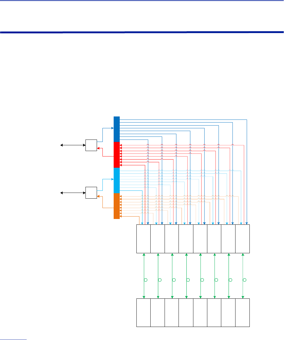
Table 43 Example of GSM link budget
Linkbudget GSM with Fiber DAS
DOWNLINK
OutputpowerDASremoteunit 30.0 dBm
Numberofcarriers 2.0 pcs Thisgivesthepercarrierpower
Powerpercarrier 27.0 dBm
SplitlossfromRUporttolastantenna 6.0 dB
Cablelosses 4.0 dB
DASantennagain 3.0 dB
EIRP 20.0 dBm
MSNoisefloor ‐121.0 dB
MSNF 3.0 dB
MSC/I 12.0 dB
MSFadingmargin 6.0 dB 10dBforvehiclemovements
Penetrationloss 0.0 dB Usedforinvehicle(10dBforcar)
AntennagainMS 1.0 dB
BodylossMS 5.0 dB
Requiredsignallevel ‐96.0 dBm Designtarget
AllowedpathlossfromantennatoMS 116.0 dB
RadiatingcablecouplinglossC95 70.0 dB Onlywhenusingradiatingcable
Lossper100m4.0dBOnlywhenusingradiatingcable
Maximumlengthofradiatingcable 1149.5 m
UPLINK
SpectralnoisefloorofBTS ‐121.0 dBm
NoisefigureBTS 3.0 dB
C/IforBTS 9.0 dB
BTSoriginalnoisefloor ‐118.0 dBm
BTSoriginalsensitivity ‐109.0 dBm
Fadingmargin 6.0 dB
FiberDASthermalnoisefloor ‐121.0 dBm
NoisefigureDASlink 3.0 dB
Numberofequallinks 3.0 pcs
Systemnetgain 0.0 dB Ifyournoiseloadishighyoushouldlowerthis
DASNoiseresult ‐118.0 dBm
NoiseloadonBTSwithDAS ‐115.0 dBm
DesensitizationonBTS 3.0 dB
NewBTSSensitivity ‐106.0 dBm
LossfromBTStoremoteantenna 7.0 dB
Sensitivityatremoteantenna ‐99.0 dB
Fadingmargin 6.0 db
Penetrationloss 0.0 dB
AntennagainMS 1.0
BodylossMS 5.0
Requiredsignallevel ‐89.0
MSOutputpower 30.0 dBm For900use33dBmfor18/1900bandsuse30
AllowedpathlossfromMStoantenna 119.0 dB
Balancedownlink‐uplink ‐3.0 dB Thisshouldpreferablybe+/‐5dB
RadiatingcablecouplinglossC95 70.0 dB Onlywhenusingradiatingcable
Lossper100m4.0dBOnlywhenusingradiatingcable
Maximumlengthofradiatingcable 1224.5 m

Systemdesign
32
Table 44 Example WCDMA link budget
WCDMA LINK BUDGET
RECEIVER SENSITIVITY AND NOISE
Noisefloor ‐108.2 dBm
ReceiverNF 6.0 dB
RXnoisepower ‐102.2 dBm
Interferencemargin 3.0 dB
RXinterferencepower ‐102.2 dBm
Noiseplusinterferencepower ‐99.2 dBm
Requestedbitrate 64.0 kbit Videocall=64.voice=12.2
Grossbitrate 3840.0 kbit
Processgain 17.8 dB
RequiredEb/No 5.0 dB
Fastfadingmargin 4.0 dB
Receiversensitivity ‐107.9 dBm
DOWNLINK CALCULATION
OutputpowerDASremoteunit 30.0 dBm
Numberofcarriers 1.0 pcs Thisgivesthepercarrier
power
Powerpercarrier 30.0 dBm
SplitlossfromRUporttolast
antenna 6.0 dB
Cablelosses 4.0 dB
DASantennagain 3.0 dB
EIRP 23.0 dBm
MSAntennagain 5.0
MSBodyloss 3.0
MSMinimumlevel ‐109.9 dBm
Allowedpathloss 137.9 dB
UPLINK CALCULATION
OutputpowerofMS 21 dBm Maximumpower
AntennagainMS 5.0 dB
BodylossMS 3.0 dB
EIRPMS 23.0 dBm
Uplinknetgain ‐10 dB
SensitivityatRUport ‐117.9 dBm
SplitlossfromantennatoRU 6.0 dB
Cablelossesfromantennato
RU 4.0 dB
DASantennagain 3.0 dB
Antennasensitivity ‐110.9 dBm
Allowedpathlossuplink 133.9 dB
Balancedownlink‐uplink 4.0
FiberDistributedAntennaSystem(FiberDAS)
33
Multiple bands
Theflexibilityofthesystemallowsforupto4bandsinoneremoteforthelowandmediumpowerremoteunits.The
high‐powerversionallows2bandsinthesamechassis,mainlybecausethepoweramplifiersaremorebulky.
Thismeansthatitisveryeasytodeployasystemfordifferentbands.Thefiberlinkisultrawidebandandcanbe
usedbetween88MHzupto2700MHzthuscoveringfromtheVHFendofthespectrumuptothelatestLTEbands.
EachbandneedstohavetheirseparateBIUintheMasterUnit.Theuplinkanddownlinksignalscanthenbe
combinedinthePOIormaybeseparateallthewayintotheFOI.TheFOIhastwoinputsandoutputsandcanthus
beconnectedtotwobandsdirectly.
Figure 16 Dual Band System Connection Diagram
900MHz
1800MHz BIU
BIU
FOI
FOI
FOI
FOI
FOI
FOI
FOI
FOI RU
RU
RU
RU
RU
RU
RU
RU
POI
Figure16
showstwoBIUcardsinterfacingwithtwoRadioBaseStations.Inthiscasetheycouldbea900GSM
stationandone1800GSMstationasanexample.Itcouldinfactbeanycombinationofserviceandfrequencyband
suchasLTE‐900orWCDMA850.

Systemdesign
34
EachBIUhasacombinedUL/DLporttowardsthebasestationandontheothersidethereareseparateUL/DLports.
TheBIUhasanuplinkamplifierandadownlinkattenuatorthatcanbeset.Thesignalsarethenconnectedtothe
POI’s4couplingfieldstoit’scommonports.Thesignalisthensplitonto8portsinthedownlinkandcombinedfrom
8portsintheuplink.FromthePOItherearethenpatchestoeachFOIcardintheframe(8inthisillustrationper
uplinkanddownlink)andthe900and1800signalarekeptseparateuntiltheFOI.
Itisnotnecessarytokeepthemseparated;theycouldbecombinedforacommonuplinkanddownlink.However,
doingsomeansthatyouhavefeweroptionsinadjustingthesignallevelswiththegainblockandattenuators,in
eachRFchain.
Multiple operators
ThesamewayasmultiplebandsandservicescanbeconnectedtotheMasterUnititisalsopossibletoconnect
severaloperators.InfactthisisoneofthekeystrengthsofaFiber‐DASsystembecauseitisaccesstechnology
agnostic.Thismeansthatitispossiblewithinthesamebandtomixdifferentaccesstechnologies–ifcareistakento
avoidproblemswhenmixingGSMandCDMAinthesamesystembecauseoftheveryslowandunsophisticated
powerregulationintheGSMuplink.
Whendesigningsuchasystem,careshouldbetakentoplacetheantennastoavoidanyusersgettingtoocloseand
causingtheRemoteUnittogointolimitmode.
Base station interface
ItisrecommendedthateachoperatoroperatestheirownBIUbecauseotherwisethesettingsoftheBIUmayaffect
morethanonesystemorservice.ThiswaydependingonthesettingsoftheindividualBaseStationtheBIUcanbe
adaptedproperlytogetthemostoutofthesystem.
Remote Unit
Multipleoperatorscanshareoneremoteunit.Doingsomeansthatconsiderationshouldbegiventothenumberof
carriersfromeachoperator,sothattheycanfulfilltheirrespectivelinkbudgets.Iftheoperatorshavealarge
numberofcarriers,suchasforsomeGSMoperatorswhoeasilyhave6,8even12carriersitwouldbebettertosplit
themuponseparateamplifiersintheRemoteUnitorevenseparateunitsaltogether.
FOI
TheFOIcanbesharedamongtheoperators.Itisrecommendedtoseetothatthedownlinksignallevelsaresimilar
sothattheysharetheavailablebandwidthofthelaserproperly.Similarlyintheuplink
POI
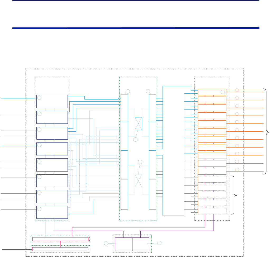
Whencombiningmultipleoperatorsitisoftenusefultocombinealltheoperators’uplinksandsplitallthe
downlinksonaper‐bandbasis.ThismeansthatifyouhavemorethanoneFOIinthesystemyoushouldlikelyneed
touseanotheroneplusahybridcombiner/splitter.
Hereisaschematiconhowthiscanbeachieved:
FiberDistributedAntennaSystem(FiberDAS)
35
Full system example
HereisanexampleofafullsystemshowingtheMasterUnitandthefibersthatgoesofftotheRemoteUnits(not
showninthisexample)withmultipleoperatorsandalargenumberoffrequencybands.
Figure 17
! !
!
!
! !
!
! !
" "
" "
" "
"
#
$
" "
%&
'(
%
%
'(
%&
'(
%
%
'(
'(
%
%
'(
%&
#$$)
'(
%
%
'(
%&
#$$)
'(
%
%
'(
%&
$$)
'(
%
%
'(
%&
$$)
!
'(
%
%
'(
%&
$$)
"
'(
%
%
'(
%&
$$)
*(+%,-+
./0
*(+%,-+
/0.0
' '
/01
' '
* *
* *
* *
* *
'%
( 0
0
'%
( 0
'%
'%
'%
'%
'%
'%
'%
'%
'%
'%
'%
'%
'%
'%
(
(
(
(
(
(
(
(
(
(
(
(
(
(
0
0
0
0
0
0
0
0
0
0
0
0
0
0
2%3
4+5+1%3%
6 7
8%9&8
6
/ /
Full System Connection Diagram
Block1:HerearealltheBaseStationInterfaceUnits(BIU)cardsforallthefrequencybandsandtheoperators.Inthis
exampletwooperatorsmayshareoneBIU.Thefirstunit1:1isforFMradiowhichisonlyDownlinkasitisbroadcast.
Thesecondunit1:2isforasafetybluelightserviceusingtheTETRAsystemon400MHz.ThentherearetwoBIU’s
1:3and1:4forGSM900,similarforGSM1800andforUMTS2100andLTE2600.
Block2:ThisisthePointofInterconnect(POI)whereallthesignalsfromtheoperatorsarecombinedonthefour
couplingfieldsofthefirstPOI(2:1).TherearetwoULfieldsandtwoDLfields.Thecommonportsarethenfedintoa
hybridcombiner(2:3,2:4)andontothesecondPOI(2:2)wherethesignalsaresplituptoconnecttoalltheFiber‐
opticInterfaces.
Block3:Thesearethefiber‐opticinterfaces(FOI)andinthisexampleupto16FOIcardsmaybeconnectedforatotal
of16RemoteUnitsifthereareoneRemoteUnitperfiber.ItispossibletouseuptofourRemoteUnitsonasingle
fiber.
Block4‐6:Thesearesupportingunitssuchaspowersupplies,theBGWwhichisthealarmandcontrolcomputerin
thesystemandtheEthernetSwitchthatconnectsthecommunicationbetweenallunitsintheMasterUnitandalso
handlesthecommunicationswiththeRemoteUnits.
Systemdesign
36
Figure 18
!"
"
#
"
"
"
"
"
!"
"
#
"
"
"
"
"
!"
"
#
"
"
"
"
"
!"
"
#
"
"
"
"
"
!"
"
#
"
"
"
"
"
!"
"
#
"
"
"
"
"
!"
"
#
"
"
"
"
"
!"
"
#
"
"
"
"
"
!"
"
#
"
"
"
"
"
!"
"
#
"
"
"
"
"
!"
"
#
"
"
"
"
"
!"
"
#
"
"
"
"
"
!"
"
#
"
"
"
"
"
!"
"
#
"
"
"
"
"
!"
"
#
"
"
"
"
"
!"
"
#
"
"
"
"
"
$
!"
"#"$
"
%!"
!"!
"
"
"
"
"
"#"$
$
!"
"#"$
"
%!"
!"!
"
"
"
"
"
"#"$
$
!"
"#"$
"
%!"
!"!
"
"
"
"
"
"#"$
$
!"
"#"$
"
%!"
!"!
"
"
"
"
"
"#"$
$
!"
"#"$
"
%!"
!"!
"
"
"
"
"
"#"$
$
!"
"#"$
"
%!"
!"!
"
"
"
"
"
"#"$
$
!"
"#"$
"
%!"
!"!
"
"
"
"
"
"#"$
$
!"
"#"$
"
%!"
!"!
"
"
"
"
"
"#"$
&'()*+
&'()*+
&'()*+
&'()*+
&'()*+
&'()*+
&'()*+
&'()*+
$",
$",
$",&
$",'
$",(
$",)
Full System Rack View

FiberDistributedAntennaSystem(FiberDAS)
37
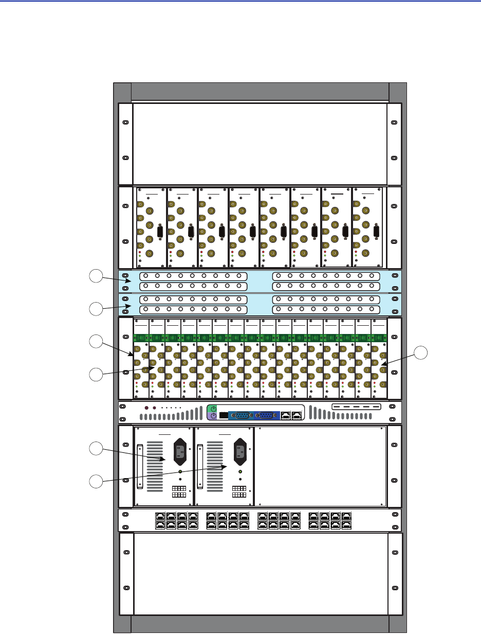
TheBlocknumbersandthenumbersinthecirclesrefertothenumbersonthepreviousconnectiondrawing.The
firstframe(BLOCK1)holdsalltheBIUinterfaces.Forclaritytheinterconnectingcablesarenotshownhere.The
secondshelf(BLOCK2)isthe2POIunitsandthehybridcombiner(2:3and2:4)ishiddeninsidethecabinet.
Thethirdframe(BLOCK3)holdstheFOIcards,upto16cardscanbeheldinonesuchframe.ThenthereistheBGW
computer(BLOCK4)tyingallthecommunicationtogetherandprovidingthewebinterfaceforsettingupand
controllingthesystem.TheBGWalsohasanoptional“northbound”fire‐walledconnectionthatcanbeconnectedto
yourownnetworkforremotesupervision,alarmandcontrol.ItcanevenbetunneledovertheInternetproviding
thereisaCGWunitwherethetunnelterminates.
BeneaththeBGWisaframecontainingaretwoPSU’s(BLOCK5).Theycanbeupgradedtofourunitstoprovide
redundancyforthisexample,twodifferentPSU’scanfeedthesameframe.
TheEthernetSwitch(BLOCK6)islocatedatthebottom,thisiswhereyouconnectalaptoptosetupandcommission
thesystem.

38
Chapter 4 Installation guidelines
ForCMRS817‐824MHzApplications:
Thisdevicecomplieswithpart15oftheFCCrules.Operationissubjecttothefollowingtwoconditions:(1)This
devicemaynotcauseharmfulinterferenceand(2)thisdevicemustacceptanyinterferencereceived,including
interferencethatmaycauseundesiredoperation.
Health and Safety
DeltaNodeDASsystemisanadvancedsystemandshouldbehandledbyskilledstaff.DeltaNodearehappytooffer
trainingofinstallationserviceprovidersinthecasethisisnecessary.
Readallavailabledocumentationandwarningsbeforehandlingtheequipment.Equipmentfailuresduetoimproper
handlingarenormallynotcoveredbytheproductwarranty.
Respectallwarningsignsontheequipmentandinthedocumentation.Makesuretoonlyoperatetheequipmenton
frequenciesallowedtouse.Donotmodifytheequipment.
TheequipmentcontainsaClass3BlaserandtheequipmentisClass1.DoneverlookintotheLaserbeamdirectlyor
indirectly,itisstronginvisiblelightandmaycauseseriousdamagetohumaneyes.
Alwaysuseprotectivecapsonfiberandconnectorendswhenfiberisremovedfromsocket.Alwayscleansocketand
connectorafterafiberhasbeenremovedbeforeitisreconnected.
Makesuretokeeppasswordsandotheroperationalinformationawayfromunauthorizedpersonnel.
Installing the Master Unit and Remotes
Allequipmentmustbeproperlygrounded.Thismeansthatthegroundpeginthemainsconnectorforbothhead‐
endgear(MasterUnit)andremotegear(RemoteUnits)mustbeconnectedtoPhase,NeutralandGroundina
properwaybeforetheplugisinsertedintheunit.
Thechassisoftheremoteandtherackofthemasterunitshouldbegroundedtoapotentialbarorsafetygrounding
barwhenoperated.Allelectricalinstallationsshouldbedonebyacertifiedelectricianonly.
WARNING
ThisisNOTaconsumerdevice.
ItisdesignforinstallationbyFCCLICENSEESandQUALIFIEDINSTALLERS.YouMUSThaveanFCCLICENSEor
expressconsentofanFCClicenseetooperatethisdevice.YouMUSTregisterClassBsignalboosters(asdefinedin
47CFR90.219)onlineatwww.fcc.gov/signal‐boosters/registration.Unauthorizedusemayresultin
significantforfeiturepenalties,includingpenaltiesinexcessof$100,000foreachcontinuingviolation.
WARNING
ThisisNOTaconsumerdevice.
ItisdesignforinstallationbyFCCLICENSEESandQUALIFIEDINSTALLERS.YouMUSThaveanFCCLICENSEor
expressconsentofanFCClicenseetooperatethisdevice.Unauthorizedusemayresultinsignificantforfeiture
penalties,includingpenaltiesinexcessof$100,000foreachcontinuingviolation.
WARNING
Avoidlookingintoconnectedfibersandreceptacles.
ThelaserusedinthissystemisaClass3blaserthatproducesinvisibleinfra‐redcoherentlight.Notsafetoview
withopticalinstruments.Alwaysputtheprotectioncapsonunusedfibersandreceptacles.

FiberDistributedAntennaSystem(FiberDAS)
39
Safety and Care for fibers
Everytimeafiberisdisconnectedandre‐connectedcareshouldbetakentoavoidgettingdustontheconnectoror
inthereceptacle.Cleanwithadryfibercleaningtoolbeforereconnectingthefiberatalltimes.Asinglespeckof
dustcanseverelyimpactthetransmission.Donottouchthefiberendswithyourfingers.Thatwillleavegreaseon
theconnectorsandmaycausesevereproblems.
WARNING
Avoidlookingintoconnectedfibersandreceptacles.
ThelaserusedinthissystemisaClass3blaserthatproducesinvisibleinfra‐redcoherentlight.Notsafetoview
withopticalinstruments.Alwaysputtheprotectioncapsonunusedfibersandreceptacles.

40
Chapter 5 Commissioning
Preparations
Theminimumofpreparationsnecessaryaretohavethesystemdocumentationwhichshouldincludethefollowing
itemsatleast:
Thesystemlayoutandblockschematic
Aconnectiondiagramforthehead‐endMasterUnit
Thetypeofconnectorsandtappersusedtointerfacetothebasestationports
ThenumberofcarriersforeachoftheBIUthatthebasestationsconnectsvia
Maximumoutputpowerforeachservicefromthebasestations
Fiberlossesshouldbedocumentedbeforehandsothatyoucancomparewhatthesystemactually
measures
Sectorizationinformation,whichsectorsshouldgotowhichremotes
DAScalculatorsheetsshowingtheexpectedsettingsforeachoftheRFchainsinuplinkanddownlink.
InformationaboutEthernetconnectionifthesystemshouldbemonitoredbyremote.Howtoconnectitto
theInternetforremoteviewingunlessyouareusingamodem.
Necessary tools
Thetoolsnecessarytocommissionthesystemincludes:
Onelaptopforchangingthesystemsettings,checkinganyalarmsandstatus.Onlysoftwareneededisa
webbrowser.OperatingsystemcanbeWindows,LinuxorMacasyouprefer.
Spectrumanalyzertomeasuretheuplink.Thesystemreliesontesttonemeasurementsintheuplinkand
thereforeitisimportanttohaveequipmenttomeasurethem
SMAtooltobeabletoconnectordisconnectBTScablesfromtheBIU.
QMAadaptersoyoucanmeasuresignalsdirectlyonthehead‐endunitssuchastheFOI,BIU,POIandso
on.
Software
Noparticularsoftwareisnecessaryexceptamoderngraphicalbasedwebbrowser.
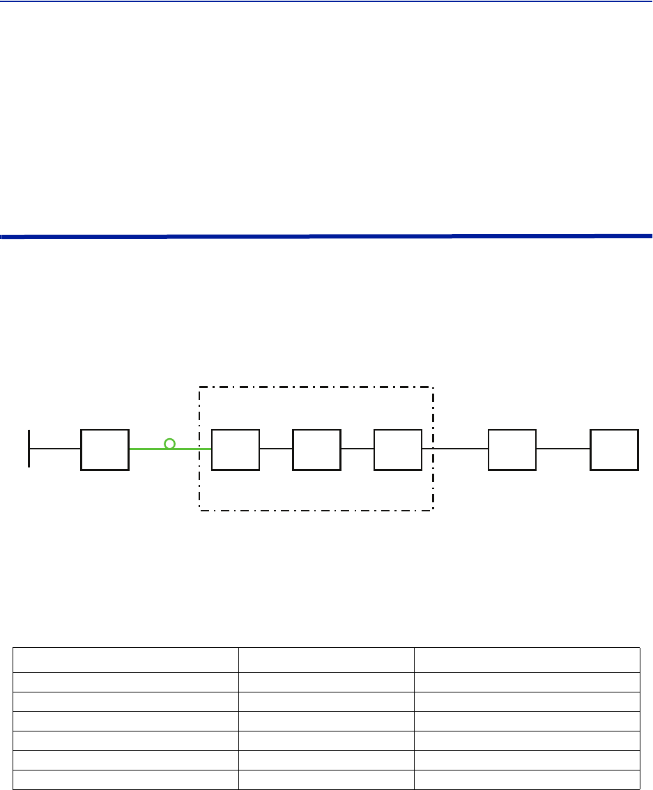
FiberDistributedAntennaSystem(FiberDAS)
41
Chapter 6 RF Commissioning
Inordertomaketheprocessmoreclearforthispartofthemanualwewillconsidersettingupafictitioussystem,
butbasedonastandardapproachatdoingFiber‐DAS.Thesystemthatweareconsideringwillhavetwofrequency
bands,let’sassumeGSM900MHzandUMTS2100MHz.Theexamplewillhave2sectorswithtworemotesineach
sector.Ofcourseyoursystemmaylookdifferent,bemoreorlesscomplexbutinordertomakeitclearhowthe
systemissetupthisshouldprovideyouwithastartingpoint.
Setting up the uplink
SettinguptheuplinkmeanstoadjustthesystemforanoptimalworkingpointfromtheantennaportoftheRemote
UnittotheactualinputontheRadioBaseStation.Thiscanbedoneindifferentwaysdependingonhowthesystem
isdesigned.Wewillherediscussastandardset‐upstartingwithasmallblockschematicshowinghowthesystemis
connected.
Figure 19
System Interconnect Diagram
Themainparameterthatwewillbediscussingisthe”netgain”ofthesystem.Thismeansthetotalchangeinsignal
fromtheRemoteUnitantennaporttothereceiverportonthebasestation.Therearedifferentwaysofsettingthis
systemupbutwewilllookata0dBnetgainsystemwhichisagoodstartingpointformostsystems.
ThesystemgaincanbecalculatedasthegainintheRemoteUnit–Lossonfiber+FOIgain–POIloss+BIUgain–
couplerloss.Basicallythistakesformofalinkbudgetandhereisanexample:
Table 45
Unit/Component Gain/Loss (dB) Accumulated Gain/Loss (dB)
RemoteUnit(RU)
Fiber‐OpticCable
FOI
POI
BIU
Coupler
Example Link Budget
BasicallythismeansthatwhateverisinputattheantennawillalsobeseenatthesamelevelfortheRadioBase
Stationreceiver.Thisisnotabadstartingpointbutdoesnottakeintoaccountthenoiseloadonthebasestation
whichwillincreasesomewhatwiththissetup
40 40
-10 30
20 50
-35 15
015
-15 0
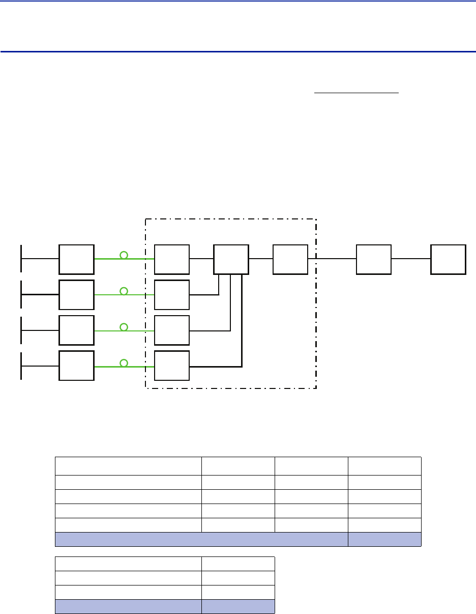
RFCommissioning
42
Noise load on Radio Base Station
Thesystemwillinevitableaddsomenoisetothereceiver.Properlysetupthenoisefigureinasystemlikethiswillbe
betterthan3dB.However,ifthegainissetuppoorly(notenoughgainintheremote,toomuchgaininthehead‐
end)itispossibletocreateaverybadnoisefigure.InordertoavoidthistheFiber‐DASCalculatorshouldbeusedto
calculatethenoisefigureofthesystemintheuplink.
IfyouhavenotfamiliarizedyourselfwiththeFiber‐DASCalculatorthenIsuggestyoudosobeforemovingoninthis
manual.ThefiguresintheFiber‐DAScalculatorrelatestothesettingsofallstepsinthechain.Byusingthecalculator
youcanfigureoutthepropersettingsonceyouknowthefiberlossbetweentheRemoteUnitandtheMasterUnit.
LetusassumeyourhavearrivedataNoiseFigureNFof3dBforthischain.Howeveryoursystemmaycontainmore
remotes,perhapsconnectedlikethis:
Figure 20
!
Multiple RU Connection Diagram
Nowthenoiseloadcanbecalculatedbyaddingthenoisecontributionfromeachstepofthechain.Belowisan
exampleofnoisefiguresfromeachoftheremotes:
Table 46
Chain NF Gain Noise Load
RU1
RU2
RU3
RU4
SumofNoiseLoad
BaseStation
Fiber‐DASNoiseLoad
TotalNoiseintoBTS
Desensitization
Noise Load
ThereisasheetintheFiber‐DAScalculatorthatletsyouaddyourfiguresandthatwillcalculateitforyou.
2.8 0.0 2.8
3.2 1.0 4.2
3.8 -2.0 1.8
2.6 -1.0 1.6
8.7
4.0
8.0
9.5
-5.5
FiberDistributedAntennaSystem(FiberDAS)
43
Whatweseehereisthatifwesetthesystemupinthisfashionwewilldesensitizethebasestationwithabout5,5
dB.ThiscanbeokayifthebasestationcoverageisonlythroughtheFiber‐DASsystembutifthebasestationisalso
beingusedforoutdoorcoverageitisnotgood.Weneedtochangethenetgaintoreflectthis.Ingeneralweshould
loweroursothatwedesensitizetheBTSonlyabout3dB.Thisvalueisagoodcompromiseandsimilartoaddinga
secondantennatothesamereceiverport(whichiskindofwhatwearedoingwiththeFiber‐DAS).
Herearethenewvalues:
Table 47
Chain NF Gain Noise Load
RU1
RU2
RU3
RU4
SumofNoiseLoad
BaseStation
Fiber‐DASNoiseLoad
TotalNoiseintoBTS
Desensitization
Adjusted Noise Load
Asyoucanseeweshouldsetthesystemupwithanetgainofabout‐5dB.Goingbacktothesettingswehadbefore
whichwas:
Table 48 Example Link Budget
Unit/Component Gain/Loss (dB) Accumulated Gain/Loss (dB)
RemoteUnit(RU)
Fiber‐OpticCable
FOI
POI
BIU
Coupler
WeonlyneedtochangetheBIUsettingusingtheattenuatorsintheBIUtolowerthegainwith5dB.Thiswill
accomplishwhatweneedtodoandtheuplinkshouldthenbecommissioned.
2.8 -5.5 -2.2
3.2 -5.5 -1.8
3.8 -5.5 -1.2
2.6 -5.5 -2.4
4.1
4.0
4.1
7.1
-3.1
40 40
-10 30
20 50
-35 15
015
-15 0
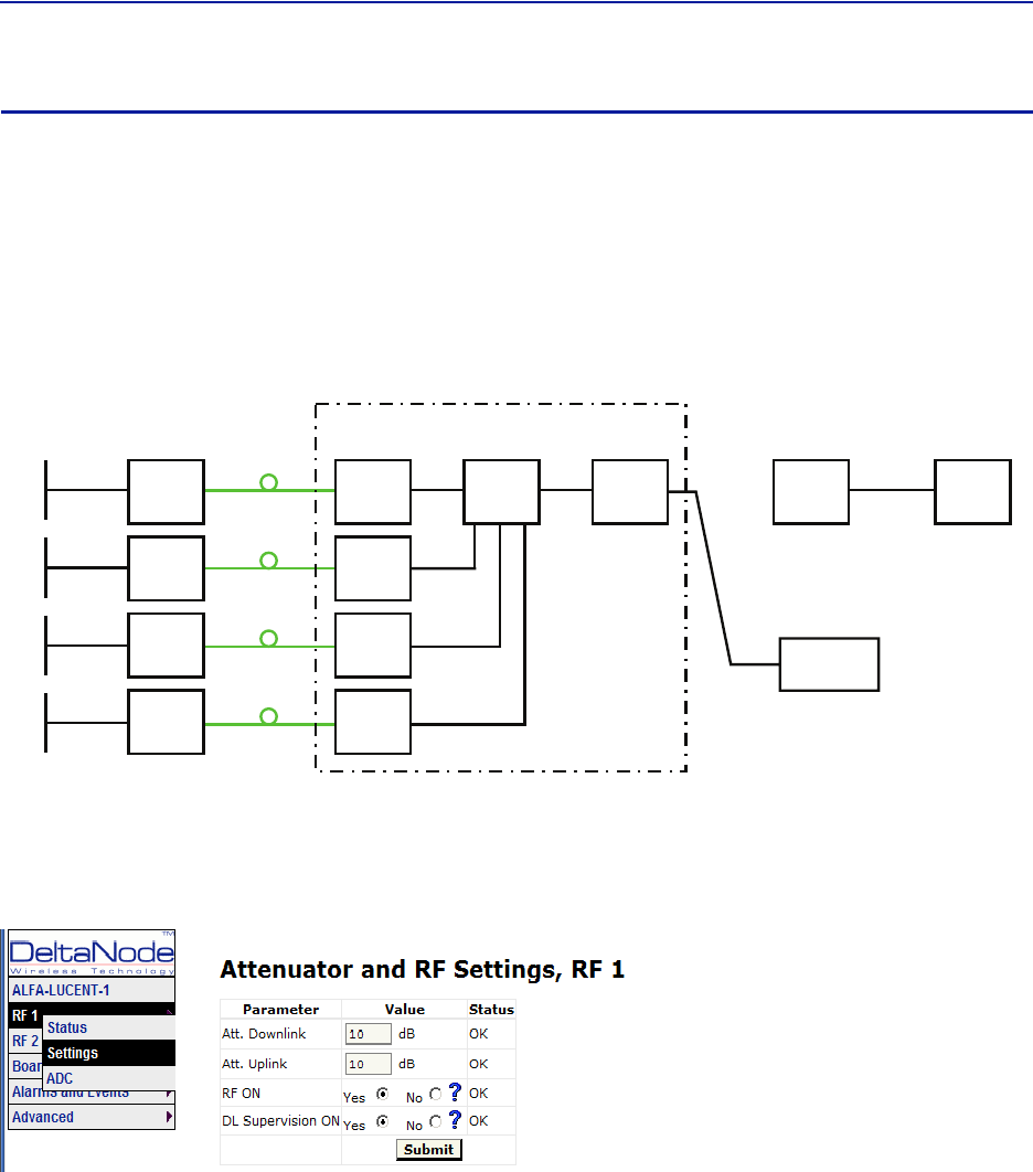
RFCommissioning
44
Practical approach
Nowthatweknowwhatweshouldhavewecaneasilysetthesystemup.Youneedaspectrumanalyzertodothis
anditiseasiesttoconnectitintotheBIUport.Rememberthatwhenyoumeasurehere,thesignalshouldalsogo
throughtheBTScouplerbeforeitreachesthebasestationreceiverport.Thereforeyoushouldexpecttoreada
valuethatis
Yourexpectedgain+thelossinyourcoupler
Ifyouwantanetgainof‐5dBandyouhavea15dBcoupler,youshouldreadanetgainof+10ontheBIUport.This
isnowwhatwearegoingtouseinthefollowingexample.
!
"#
Turn on the RF
ConnecttotheBIUandturnontheRF.Settheattenuatorinthemediumrangefortheuplinkthatyouare
measuring.Thisallowsyoulatertoadjustitupanddownasnecessarytogetthecorrectgainfortheuplinkchain.
Settingthemto10dBisagoodidea.DLsupervisioncanbeleftasisfornowandalsoDLattenuationwhichwewill
setuplater.
ConnecttotheFOIcardandselectOptoandRF–RFConfigandsetitupaccordingtoyourFiber‐DAScalculator
settings.DonotforgettoturnRFon.
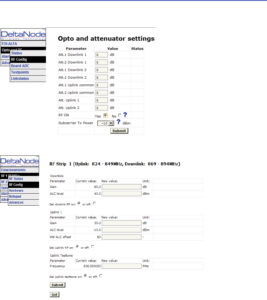
FiberDistributedAntennaSystem(FiberDAS)
45
Nextstepistoconnecttotheremoteunitandsetitupfortestmeasurementintheuplink.
InthisscreenyoushouldalsoturnRFon,setthegaintoabout35dBasastartingpointandthenturnontheuplink
testtone.Notethefrequencyofthetesttone,thisisthefrequencyyoushouldbemeasuringonyourspectrum
analyzer.
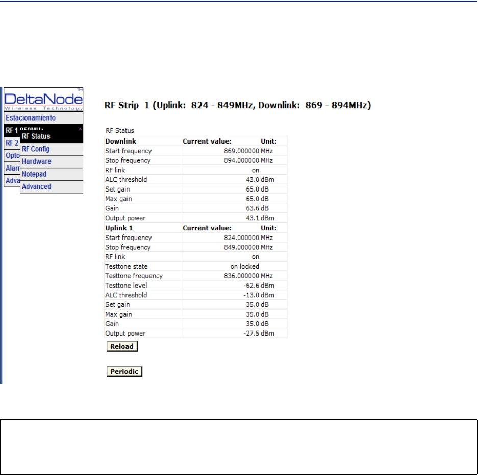
RFCommissioning
46
Turnonthespectrumanalyzer,makesureitisconnectedtotherightportontherightBIUandthenfindthe
frequency.Areasonablespanis1MHzandthereceiverbandwidthcanbesetto30kHzorsimilar.Usethemarkerto
measurethepeakofthesignal.Thengotothenextscreenontheremoteunit,theRFStatusscreen.
WhatwearelookingforhereistheTesttoneLevel.Notethisdownaswell,nexttothefrequencyofthetesttone
younotedearlier.
Thencheckyourspectrumanalyzer.Assumingyourtesttonelevelis‐62,6dBmasinthisexampleyourspectrum
analyzermayshow‐58,2dBm.CalculatingthenetgainbetweentheRUandtheBIUwillthenyield‐58,2‐‐62,5=4,3
dB.SubtractthecouplerbetweentheBIUandtheradiobasestationwhichinthisexamplewas15dBandweget‐
19,3dBasournetgain.
Wewanted‐10dBsowehave9,3dBtoolowgain.Weshouldthenincreasethegainandthebestplacetodothis
wouldbeintheremoteunitbysettingthegainat35+9,3=44,3whichwewillroundto44dB.
Thatuplinkisnowfinishedandwewillrepeatthesettingsforallofouruplink,oneatatime.
CAUTION
TurnOffTestTone
Donotforgettoturnoffthetesttonewhenyouaredonewithyouruplink.Bettercheckoneextratime.Theywill
otherwiseinterferewiththenormaloperationofthesystembycausingnoisetothebasestation.
47
Chapter 7 Model Identification
System Model Numbers
Examples:
DDR4-GC0-PA1-AD — 4band,33dBmpoweroutputperband,Fullband700combinedwithCell850non
duplexed,PCScombinedwithAWSduplexed,ACpowered,7/1 6 DIN,1310nmuplink
DDR4-GC0-PA1-AD-B12-C34-WUBCS — 4band,33dBmpoweroutputperband,Fullband700combined
withCell850nonduplexed,PCScombinedwithAWSduplexed,ACpowered,7/1 6 DIN,Bands1and2(700and850)
1290nmuplink,Bands2and3(PCS&AWS)1310nmuplink,CWDM,fibersplit(3dB)fordaisychainedremotes
!
"
#
"
#
$%&'
('
)'$&
*
!
"
#
"
#
+
+
,
+
-
+
.
-
-
-
,%*/'
0%*1'
.%*-'
%*'
%--'
2%"(34
%
%.5-/%1*6
7%75-8#%*##6
%!5*#/%*+#6
%75*#%*-#6
,%,.5*9#%*1#6
:%9##.;7%5*1#%9+6
4%431##
.%.1##
!%1##
%(1##51<-%8#96
%8##
%89#
)%<##
%58##6
(%(
=%=75<##>+##6
%51##>+##6
?%=7%?5+/##6
@%8##
#%)%"
%"
2A
#%)%"5,6
%"5,6
+%)%"506
-%"506
*%)%"5.6
9%"5.6
/%)%"56
1%"56
8%)%"56
<%"56
!
+
-
*
"#$
%,
58/%+/*>6
%*8
%&'(#)
,""""%'$'
BC$&
C$%"
35$&""""
',436
""""%'
3BC$&&'
C$%"
35$&""""
'436
%#!
)%)%
%1>/=)
%=)
&'
%"5,44
'C$6
&$#*+,
5+-
'C$B6
%+1#
%+<#
%-#5&&'6
%--#
?%-9#
%-1#
!%-<#
.%*#
=%*-#
@%*9#
D%*1#
4%*<#
%9#
)%9-#
%99#
(%91#
-. !
5&'$
6
&C$B5
'E6
FF+-3$=
$G+G-
+
-
*
-#/#(#)
"%C$ %
'%"
5-&$6

ModelIdentification
48
Remote End Unit Part Numbers
Note: Theremoteendunitsarecompletelyintegratedatthefactory,thereisnofieldassemblyother
thanmountingandcableconnection.Modulesshouldnotbealteredoncedeployed.
Public Safety DDR Module Numbers
Part Number Frequency Band IC Certification Number
MOD‐DDR‐VVHF‐136‐174MHz 110141A‐DDR1V
MOD‐DDR‐UUHF‐450‐470MHz 110141A‐DDR1U
MOD‐DDR‐QT‐Band‐470‐512MHz 110141A‐DDR1Q
MOD‐DDR‐F700MhzPS 110141A‐DDR1F
MOD‐DDR‐S800MHzPS 110141A‐DDR1S
Cellular DDR Module Numbers
Part Number Frequency Band IC Certification Number
MOD‐DDR‐G700cellfullband 110141A‐DDR700FB
MOD‐DDR‐C850cellband 110141A‐DDR850
MOD‐DDR‐P1900PCS 110141A‐DDR1900
MOD‐DDR‐A2100AWS 110141A‐DDR2100
MOD‐DDR‐E2600 110141A‐DDR2600

FiberDistributedAntennaSystem(FiberDAS)
49