Dialog Semiconductor SC14A DECT Cordless Voice Module User Manual SC14CVMDECTv1 2ls
Dialog Semiconductor BV DECT Cordless Voice Module SC14CVMDECTv1 2ls
UserManual.wiki
>
Dialog Semiconductor
>
SC14A User Manual
>
user manual
Contents
1.
user manual
2.
user manual safety requirements
user manual
Navigation menu
Upload a User Manual
Namespaces
Wiki Guide
HTML
PDF
Info
Views
User Manual
Discussion / Help
Navigation
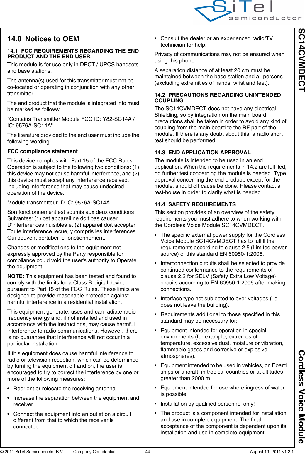
![SC14CVMDECT Cordless Voice Module© 2011 SiTel Semiconductor B.V. Company Confidential 3 August 19, 2011 v1.2.11.0 Connection Diagram1.1 PIN DESCRIPTIONFigure 1 Connection Diagram (Bottom View)MLKJHGFEDCBA121110 9 8 7 6 5 4 3 2 1Table 1: Pin descriptionPin Module Pin nameIn/OutIoutDrive(mA)Reset State DescriptionA1 GND -- -GroundA2 GND -- -GroundA3 GND -- -GroundA4 NC - - I leave unconnectedA5 VDDIO I - - Supply voltage for internal QSPI and data flash. Must be connected to VDD (1.8V).A6 P1[2]/INT2 IO 2 I-PU I/O port.INT2: Interrupt Input.A7 GND -- -GroundA8 GND -- -GroundA9 VBAT I - - Main supply voltage <5.5V. Can be directly connected to a Li-Ion battery. A10 P0[4] / SPI_EN IO 8 I-PU I/O portSPI_ENA11 RSTn I 1 I-PU(200k pull-up)Active low Reset input with Schmitt-trigger input, open-drain output and pull up resistor to internal VDD. Input may not exceed 2.0 V. An internal capacitor of 100nF is mounted on this pin.B1 GND -- -GroundB2 GND -- -GroundB3 CP_VOUT1 O - I Charge Pump Output 1.Must be connected through a capacitor of 1uF to gndB4 P1[5]/INT5 IO 8 O-1 I/O PortINT5: Interrupt Input.](https://usermanual.wiki/Dialog-Semiconductor/SC14A.user-manual/User-Guide-1546287-Page-3.png)
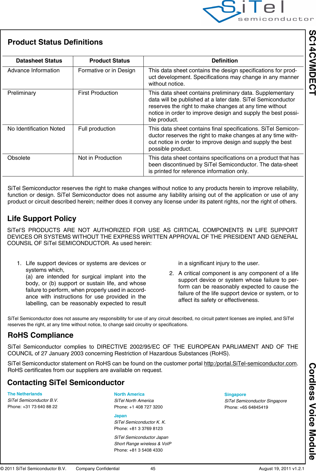
![SC14CVMDECT Cordless Voice Module© 2011 SiTel Semiconductor B.V. Company Confidential 4 August 19, 2011 v1.2.1B5 GND -- -GroundB6 P2[6]/INT6 / WTF_INIO 2 I-PU I/O portINT6: Interrupt Input.WTF_IN: -B7 P0[5] / SPI_CLK IO 8 I-PU I/O PortSPI ClockB8 GND -- -B9 P0[1] / URX IO 8 I-PD(10k)I/O portUART Serial InB10 VBATT I - - Secondary supply voltage. Connect to VCCRF.B11 GND -- -GroundB12 NC - - - RF pad, no pad on PCBC1 GND -- -GroundC2 PAOUTn IO 500 O-0 (5k fixed pull-down)CLASSD loudspeaker positive outputC3 GND -- -GroundC4 P2[7]/INT7 IO 8 I-PU I/O portINT7: Interrupt C5 P1[4]/INT4 IO 1/2 I-PD I/O portINT4: InterruptC6 P1[1]/INT1 IO 2 I-PU I/O Port INT1: InterruptLE: - INT6: secondary InterruptC7 GND -- -GroundC8 P0[0] / UTX O 8 I-PU I/O PortUART Serial OutC9 GND -- -GroundC10 JTAG IO 8 I-PU JTAG-SDI+; one wire Debug interface with open-drain.Pullup with R=1k to Vdd.C11 VCCRF I - - RFSUPPLY input < 3.45V. Connect to VBAT if VBAT less than 3.45V. Else this pin must be supplied from and external 3.3V LDO.Refer to Table 16 for supply requirements.D1 GND -- -GroundD2 PAOUTp IO 500 O-0 (5k fixed pull-down)CLASSD loudspeaker positive outputsD3 PON I I (270k fixed pull-down)Power on, Switches on the device if Voltage > 1.5V. May be directly connected to VBAT, also with Li-Ion batteriesTable 1: Pin description (Continued)Pin Module Pin nameIn/OutIoutDrive(mA)Reset State Description](https://usermanual.wiki/Dialog-Semiconductor/SC14A.user-manual/User-Guide-1546287-Page-4.png)
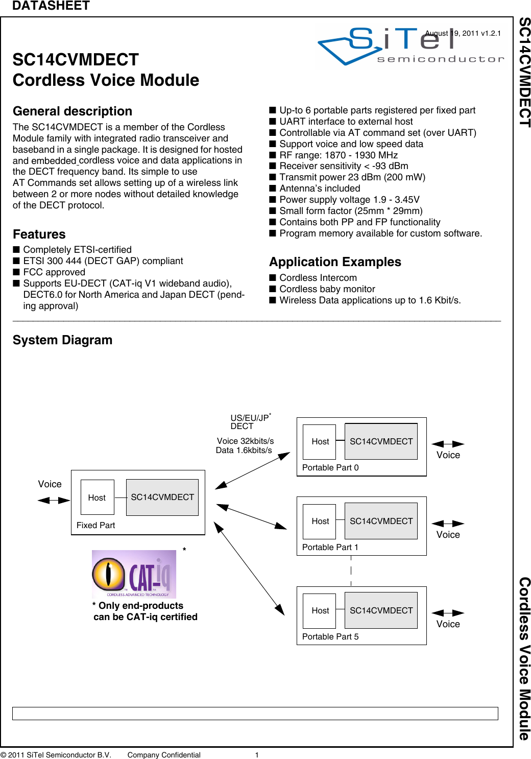
![SC14CVMDECT Cordless Voice Module© 2011 SiTel Semiconductor B.V. Company Confidential 5 August 19, 2011 v1.2.1D4 CHARGE I - I-PD(270k fixed pull-down)Charger connected indication. Switches on the device if voltage > 1.5v. Must be connected to charger via resistor R>(Vcharger_max-3V)/10 mA (round to next largest value in range). If no charger used, Leave unconnected if not used.Charger is currently not supported.D5 GND -- -GroundD6 GND -- -GroundD7 GND -- -GroundD8 GND -- -GroundD9 P2[4]/SCL1/PCM_DOIO 8 I-PU I/O port SCL1; I2C clockPCM_DO: PCM Data outputD10 VDD O - - Digital Core supply voltage (1.8V TYP).Output from internal regulator.D11 P2[5]/PCM_FSC IO 8 I-PU I/O PortPCM_FSC: PCM Frame SyncE1 VDDPA I - - CLASSD Audio Amplifier supply voltage up to 3.45V.E2 GND -- -GroundE3 CHARGE_CTRL O - O-0 Charge control pin.Leave unconnected if not used.Charger is currently not supported.E4 SOCn I - I Battery State Of Charge negative input. Star point connected to the SOC resistor. Charger is currently not supported: connect to GNDE5 GND -- -GroundE6 GND -- -GroundE7 GND -- -GroundE8 GND -- -GroundE9 GND -- -GroundE10 P0[7] / SPI_DI IO 8 I-PU I/O PortSPI Data InputE11 GND -- -GroundF1 SOCp I - I Battery State of charge positive input.Charger is currently not supported: connect to GNDF2 P1[0]/INT0/ADC1 IO 2 I-PU I/O PortINT0: Interrupt 0ADC1; ADC input 1F3 ADC2/NTC I - I ADC2NTC protection input for Li-Ion charger circuit.Charger is currently not supported: connect to GNDF4 NC - - - leave unconnectedF5 ULP_PORT I - I Ultra Low Power Port PinUltra low power is not supported by the software, connect to gnd.F6 ULP_VBAT I - I Ultra Low Power Supply PinUltra low power is not supported by the software, connect to gnd.Table 1: Pin description (Continued)Pin Module Pin nameIn/OutIoutDrive(mA)Reset State Description](https://usermanual.wiki/Dialog-Semiconductor/SC14A.user-manual/User-Guide-1546287-Page-5.png)
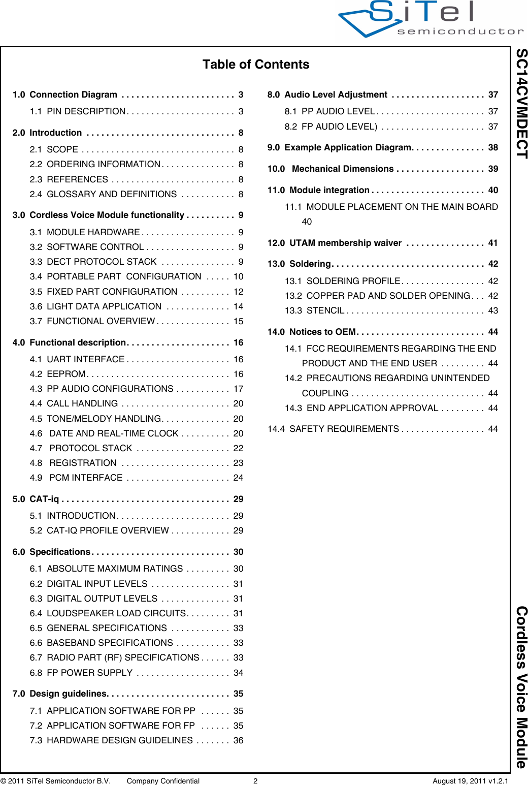
![SC14CVMDECT Cordless Voice Module© 2011 SiTel Semiconductor B.V. Company Confidential 6 August 19, 2011 v1.2.1F7 ULP_MAIN_CTRL- I-0 Ultra Low Power Main ControlUltra low power is not supported by the software, connect to gnd.F8 NC - - - RF pad, must be left unconnectedF9 P2[3]/SDA1 / PCM_DIIO 8 I-PU I/O PortSDA1: I2C DataPCM_DI: PCM Data inputF10 P1[3]/INT3 IO 1/2 I-PD I/O PortINT3: InterruptF11 P0[6] / SPI_DO IO 8 I-PU I/O PortSPI Data OutG1 GND -- -GroundG2 LSRn O - O Negative loudspeaker outputG3 GND -- -GroundG4 P3[3]/ADC0 IO 8 I I/O PortADC0; ADC input 0G5 GND -- -GroundG6 NC - - - leave unconnectedG7 GND -- -GroundG8 NC - - - leave unconnectedG9 GND -- -GroundG10 GND -- -GroundG11 GND -- -GroundH1 VREFM - Negative microphone reference (star point), connect to gnd.H2 LSRp O - O Positive loudspeaker outputH3 P3[7]/RINGp IO 4 I I/O PortRINGp: Ringer detection inputH4 NC - - -H5 GND - - I GroundH6 GND - - I GroundH7 P2[2]/PCM_CLK I/O 8 I-PD I/O PortPCM_CLK: PCM clock input/outputH8 NC - - - RF pad, must be left unconnectedH9 GND -- -GroundH10 GND -- -GroundH11 GND -- -GroundJ1 GND -- -GroundJ2 MICh I - I Headset microphone input with fixed input protectionJ3 GND -- -GroundJ4 P3[5]/RINGING / RINGOUTIO 4 I I/O PortRINGING: Ring detection InputRINGOUT: - J5 GND -- -GroundJ6 NC - - - RF pad, must be left unconnectedTable 1: Pin description (Continued)Pin Module Pin nameIn/OutIoutDrive(mA)Reset State Description](https://usermanual.wiki/Dialog-Semiconductor/SC14A.user-manual/User-Guide-1546287-Page-6.png)
![SC14CVMDECT Cordless Voice Module© 2011 SiTel Semiconductor B.V. Company Confidential 7 August 19, 2011 v1.2.1• “NC” means: leave unconnected.•GND means internally connected to Ground plane of module (51 pins in total)• GND means connect to Ground (not supported, functional pin)Reset States:• I = Input• O= Output• I-PD = Input, pulled down• I-PU = Input, pulled up• O-0 = Output, low• O-1 = Output, highJ7 GND -- -GroundJ8 P2[1] / PWM1 / LED4IO 8 I I/O PortPWM1: Pulse Width Modulation outputLED4: 2.5/5mA LED current sinkJ9 GND -- -GroundJ10 GND -- -GroundJ11 GND -- -GroundK1 VREFp O - I Positive microphone supply voltageK2 MICp I - I Positive microphone inputK3 P3[2]/CIDINp IO 8 I I/O PortCIDINp: Caller id opamps positive inputK4 P3[6]/RINGn IO 3 I I/O PortRINGn: RING opamp negative inputK5 P3[4]/PARADET IO 8 I I/O PortPARADET: Parallel set detectionK6 NC - - - leave unconnectedK7 NC - - - leave unconnectedK8 P2[0]/ PWM0 / LED3IO 8 I I/O PortPWM0: -LED3: 2.5/5mA LED current sinkK9 GND -- -GroundK10 NC - - - No ground under the pad (RF sensitive)K11 NC - - - No ground under the pad (RF sensitive)L1 GND -- -GroundL2 MICn I - I Negative handset microphone inputL3 GND -- -GroundL4 GND -- -GroundL5 NC - - - RF pad, must be left unconnectedL6 GND -- -GroundL7 GND -- -GroundL8 NC - - - leave unconnectedL9 GND -- -GroundL10 NC - - - No ground under the pad (RF sensitive)L11 GND -- -GroundM2 NC - - - RF pad, no pad on PCBTable 1: Pin description (Continued)Pin Module Pin nameIn/OutIoutDrive(mA)Reset State Description](https://usermanual.wiki/Dialog-Semiconductor/SC14A.user-manual/User-Guide-1546287-Page-7.png)
![SC14CVMDECT Cordless Voice Module© 2011 SiTel Semiconductor B.V. Company Confidential 9 August 19, 2011 v1.2.13.0 Cordless Voice Module functionalityThis section describes the key functions and features supported by the SC14CVMDECT as shown in Figure 2.3.1 MODULE HARDWARE The SC14CVMDECT internal hardware consist of:• An Internal Microprocessor (MCU) running from FLASH handling the AT command interpreter, the protocol stack and further internal control.• A 4kByte EEPROM used by the protocol stack and for user EEPROM variables.• A DSP for the Audio signal processing like ADPCM voice compression towards the Codecs.• A codec to convert the analog signals to digital signals and vise versa.• Input/Output ports which can be toggled high/low if output or a high/low digital level can be read.• A 10.368 MHz XTAL clock. This crystal is automatically tuned by the module software for the best Radio Performance.• Voltage regulators to convert the external supply voltage to a stable supply voltages for the core and I/O’s.• A DECT Radio transceiver with two built-in antenna circuits. The antenna’s are on the module, so no RF knowledge is required.• A UART for communication to a host.3.2 SOFTWARE CONTROLThe SC14CVMDECT can be controlled via an AT Command Set over the UART interface or from the internal user application. The external controller handles the user interface (MMI) and sends/receives AT commands and responses to the internal protocol stack. A detailed functional and data flow description, including an example of the start-up sequence, can be found in document reference [1].3.3 DECT PROTOCOL STACKThe SC14CVMDECT internal protocol stack is based on the ETSI DECT specifications and is compliant with ETSI 300 444 (GAP).The product supports up to 6 DECT GAP compliant PP units to one FP station.Figure 2 SC14CVMDECT functional overviewUART interfaceto hostAT commandsAT commandinterpreterRadioProtocolStack DSPPortsDECTEEPROM XTALFLASHCodecUserMICLSRHeadset ControlUARTSWSPI](https://usermanual.wiki/Dialog-Semiconductor/SC14A.user-manual/User-Guide-1546287-Page-9.png)
![SC14CVMDECT Cordless Voice Module© 2011 SiTel Semiconductor B.V. Company Confidential 14 August 19, 2011 v1.2.13.6 LIGHT DATA APPLICATIONThe SC14CVMDECT supports Low Data Rate (LDR) transmission up to 1.6 kbits/s. Packets with a length of upto 30 bytes payload can be transmitted and received.One SC14CVMDECT is configured as FP and the others are configured as PPs (Figure 5). The host sends/receives AT commands (over UART) to/from PP or FP as shown in Table 4.Up to six PPs can be registered to one FP.See document reference [1] for more information on the AT commands to support LDR. Table 4: Low Data ServicesDirection Supported CommentHost to PP to FP YesHost to FP to PP YesPP to PP Yes Indirect via FPFigure 5 Light Data application1.6 kbits/s1.6 kbits/sSC14CVMDECTSC14CVMDECTSC14CVMDECTPPFPPP](https://usermanual.wiki/Dialog-Semiconductor/SC14A.user-manual/User-Guide-1546287-Page-14.png)
![SC14CVMDECT Cordless Voice Module© 2011 SiTel Semiconductor B.V. Company Confidential 16 August 19, 2011 v1.2.14.0 Functional description4.1 UART INTERFACEThe UART isnormally used for AT commands, but can also be used for software upgrades and debugging. The UART is a full duplex UART with frame type: 1 start bit, 8 data bits (LSB first), 1 stop bit, no parity and a baud rate of 115.200 kBaudThe UART hardware interface uses 3 wires(see Figure 6) .Caution: All signals are 1.8 V. An external V.24 line driver must be provided if the UART port of the module is connected to a standard V.24 device. Connecting the module without a driver may damage the module.4.2 EEPROM4.2.1 EEPROM layoutThe SC14CVMDECT PP and FP include a 4 Kbyte EEPROM which is divided into two areas (see Table 6).A detailed overview of the EEPROM parameter is found in document reference [2].Some parts of the EEPROM parameters are read into the SC14CVMDECT during the start up and other parts are used by the SC14CVMDECT software during execution. The EEPROM parameters are divided into 2 types:• Factory type • normal type. The factory type is specific for the SC14CVMDECT and should only be set by production. The factory types are either parameters for adjustments used by the baseband or the radio interface, or is used to setup the SC14CVMDECT into special modes. The factory types will only be modified by changing the factory programmed default value. See document reference [2]. Only users with “debug” authorization can modify these EEPROM parametersThe other “normal” EEPROM parameters can be reset to default values by running a soft default setting (default batch file).4.2.2 EEPROM access by MCUThe host is able to read or modify the EEPROM parameters or limited free EEPROM areas via AT commands AT+WEExx. Access to the EEPROM parameters depends on the authorization level set by the AT+WULA parameter:0 = Anonymous User with Lowest Authority (not able to read from and write to EEPROM)1 = Power User. Able to read from all EEPROM locations and write to locations 0x0F00..0x0FBF (user space). Password: 748357.2 = Debug User Highest Authority.Able to read from and write to EEPROM (audio and stack related parameters. Contact SiTel Semiconductor for the password.Figure 6 UART hardware configurationTable 6: EEPROM mapEEPROM space Size UsageSC14CVMDECT 3.6 Kbyte Used for RF, audio, battery, tone setup, data base, etc.User 0.4 Kbyte. Can be used for MMI applications such as User information.](https://usermanual.wiki/Dialog-Semiconductor/SC14A.user-manual/User-Guide-1546287-Page-16.png)
![SC14CVMDECT Cordless Voice Module© 2011 SiTel Semiconductor B.V. Company Confidential 18 August 19, 2011 v1.2.14.3.2 Audio ModesThe PP audio handling consists of four audio states. In these states the audio subsystem is configured for a certain audio mode:1. Idle state (not relevant for microphone configuration)2. Earpiece Mode (Handset Speaker)3. Handsfree or Speakerphone Mode4. Headset modeSelection between the modes is done by API calls; see document reference [1].The Alert state is for tone playing and is entered automatically when tones are played using the API calls. The Alert state can originate from idle earpiece, handsfree or headset state.Figure 9 PP Audio mode](https://usermanual.wiki/Dialog-Semiconductor/SC14A.user-manual/User-Guide-1546287-Page-18.png)
![SC14CVMDECT Cordless Voice Module© 2011 SiTel Semiconductor B.V. Company Confidential 19 August 19, 2011 v1.2.14.3.3 PP Audio Codec adjustmentThe audio codec settings for the loudspeaker and Microphone must be preconfigured in the EEPROM for each mode. The EEPROM parameter fields for Audio.Earp.xxx, the Audio.Heads.xxx and Audio.SpkPh.xxx have a default value but may be modified to tune the settings.4.3.4 General Audio adjustmentFor each audio mode, the receive (RLR) and transmit (SLR) audio paths must be adjusted. RLR and SLR are adjusted in the registers in the EEPROM for each audio state; see document reference [2].4.3.5 Power managementTo minimize the current consumption the PP will shutdown all codec amplifiers in Idle state. This means that all reference voltages in the front-end will be disabled. This feature can be disabled in the EEPROM if the reference voltages for some reasons are needed in Idle state.4.3.6 Earpiece ModeIn Earpiece mode (Handset Speaker) an artificial sidetone is generated. The level of the sidetone can be adjusted and setup in the EEPROM through parameter fields Audio.Earp.Vol.Elementx,SideToneGain and Audio.Heads.Elementx.SideToneGain. In Earpiece mode it is possible to adjust the volume in the Earpiece via the API calls. In Earpiece mode the PP audio is routed as shown in Figure 11.4.3.7 Alert modeThe Alert mode is for generating tone and melodies in the Speakerphone loudspeaker. In Alert mode it is possible to adjust the volume in the speaker via the API calls.4.3.8 PP Volume The PP supports 6 volume steps, which are EEPROM configurable through parameter fields Audio.Earp.Vol.xxx, the Audio.Heads.Vol.xxx and Audio.SpkPh.Vol.xxx. The volume steps must be set initially in the EEPROM during production..Inband tones will be affected by the volume adjustments, since the volume control is placed after tones are added to the signal..Figure 11 shows the Audio flow. Here is the list of main functions:EQ Equalizernc100Hz 100Hz cancellerSidetone SidetoneEC Echo CancellerVol. Ctrl Volume ControlTonegen Tone generatorFigure 10 Handset Volume Configuration](https://usermanual.wiki/Dialog-Semiconductor/SC14A.user-manual/User-Guide-1546287-Page-19.png)
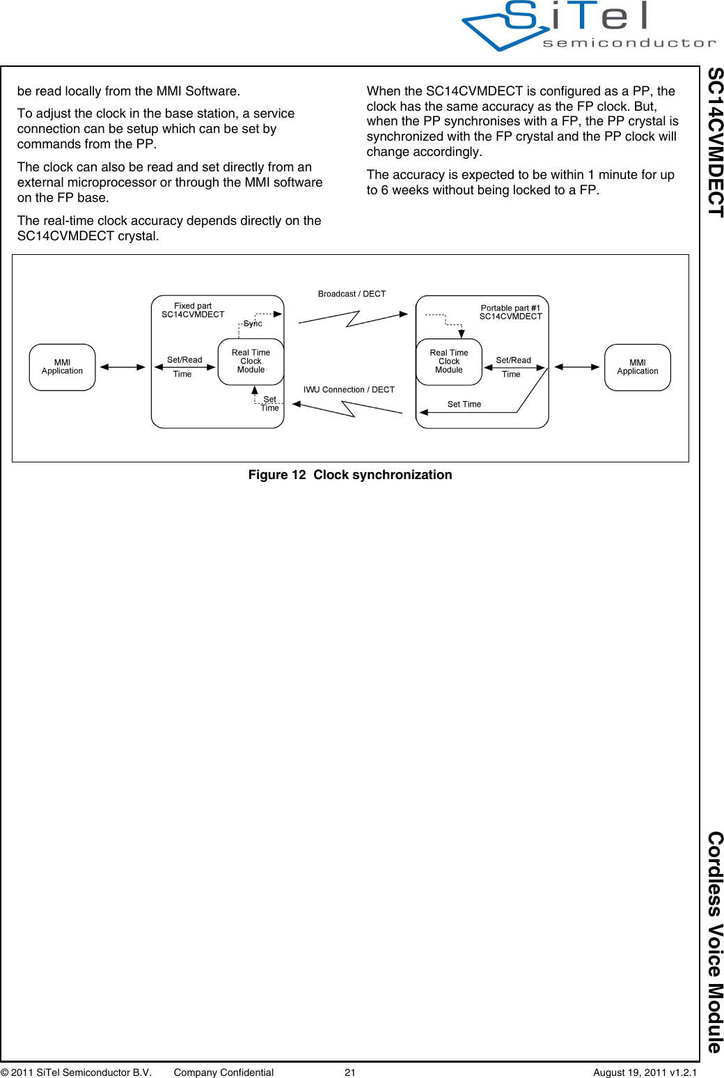
![SC14CVMDECT Cordless Voice Module© 2011 SiTel Semiconductor B.V. Company Confidential 20 August 19, 2011 v1.2.1.4.3.9 PP Audio equalizationTo enable adjustments of the frequency response the PP contains four programmable filters: 2 in RX direction and 2 in TX direction (see Figure 11).By default these filters are loaded with bypass coefficients, but the API contains commands to load new coefficient for all filters.Equalizer filters are part of the audio routes for all audio modes and are placed as shown in Figure 11.For a detailed description of the filter functionality please refer to API documentation; see document reference [1].4.4 CALL HANDLING4.4.1 FP to PP CallWhen the FP initializes a call to a PP, a radio connection is set up to all the PP applications to make it possible for the PP Application Software to indicate that there is an incoming call.It is possible to configure the ringing indication using broadcast to make all 6 PPs ringing. When receiving the call, the PP signals the call to the MMI Software.4.4.2 PP to FP CallWhen the MMI Software signals the PP to establish a call, the PP opens the radio connection to the FP. 4.4.3 Intercom and ConferenceNot supported.4.4.4 Call TransferCall transfers are not supported.4.4.5 Page CallThe Page call is a FP functionality used to locate the registered PPs. FP paging does not establish a normal audio connection and is terminated when answered by the PP. In FP Speakerphone mode a voice call can be established when the paging is answered.4.4.6 Connection scenariosThe following voice connections are supported.• PP to FP• FP to PP.4.5 TONE/MELODY HANDLINGThe tone component handles the generation of various tones in the device. Both tones/melodies in a FP and PP configuration are supported. Main features of the tone component are:The main features of the tone component are:• Ringer tones and melodies (7 tone polyphonic)• Alert tones (key sound, error tones, confirmation tones, etc.)• Inband tones (dial tone, net-congestion tone, busy tone, etc.)• Single tone generation4.6 DATE AND REAL-TIME CLOCKThe FP base has a real-time clock feature, which (when activated) broadcasts the date and clock to the PPs. Activation of the date and real-time clock is done by setting the date and clock via the PP.The clock is with hours, minutes and date. The clock supports the leap year. Daylight saving is not supported and must be handled by the MMI application.The PP clock is synchronized with the FP every time a broadcast is received. If the PP goes out-of-lock, the PP itself calculates the clock until the PP is again within the range of the FP. The updated clock can then Figure 11 PP Audio RoutingEQEQ nc100HzECVol.ctrltonegenRx_inTx_outSidetone](https://usermanual.wiki/Dialog-Semiconductor/SC14A.user-manual/User-Guide-1546287-Page-20.png)
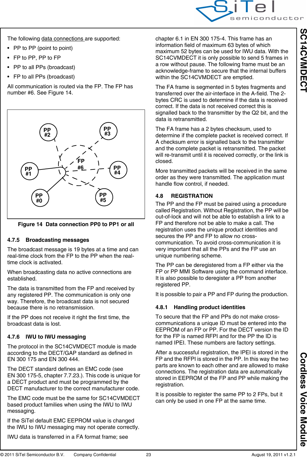
![SC14CVMDECT Cordless Voice Module© 2011 SiTel Semiconductor B.V. Company Confidential 22 August 19, 2011 v1.2.14.7 PROTOCOL STACKThe protocol stack handles the RF interface. For the SC14CVMDECT the DECT TDMA is used. The protocol features encryption.4.7.1 DECT TBR22The SC14CVMDECT protocol supports the DECT GAP standard. DECT TBR22 GAP type approval however is optional.To pass a GAP type approval, a disable of the PP authentication and encryption during conversation is needed for some TBR22 test cases (DLC test cases). This can be done via EEPROM address 0x00F0.4.7.2 Out-of-Range handlingWhen the PP goes in-range or out-of-range a signal is sent from the PP to the MMI Software indicating whether the PP is in-lock or is out-of-lock with the FP.4.7.3 Pre-amble Antenna diversityTo optimize the audio quality caused by rapid changing radio paths (fading), the SC14CVMDECT supports pre-amble antenna diversity. The pre-amble diversity algorithm uses RSSI measurements to judge the radio signal strength on both antennas and, as a result of it, the choice of the best performing antenna is determined. The antenna will be used for the receive slot and the next transmit slot.The pre-amble antenna diversity is supported by default. The pre-amble diversity can be disabled by EEPROM to let the SC14CVMDECT support a single antenna. See document reference [2].In general an FP uses diversity and a PP does not.4.7.4 Low Speed DataDuring a voice call or using a service call, data can be transferred at a rate of about 1.6 Kbit/s using IWU to IWU messaging..Figure 13 Low Speed Data ScenarioFPPPPP](https://usermanual.wiki/Dialog-Semiconductor/SC14A.user-manual/User-Guide-1546287-Page-22.png)
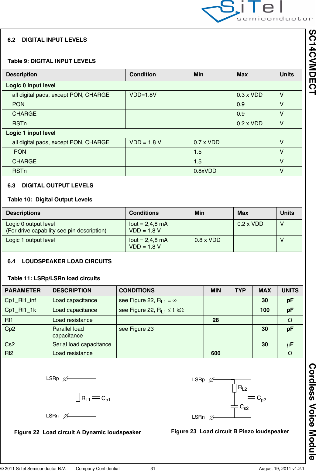
![SC14CVMDECT Cordless Voice Module© 2011 SiTel Semiconductor B.V. Company Confidential 30 August 19, 2011 v1.2.16.0 Specifications6.1 ABSOLUTE MAXIMUM RATINGSNote 1: Absolute maximum ratings are those values that may be applied for maximum 50 hours. Beyond these values, damage to the device may occur.Table 7: Absolute Maximum Ratings (Note 1)Description Condition Min Max UnitMaximum supply voltages:VBAT 5.5 VVBATT, VCCRF, VDDPA 3.6 VVDDIO 2 VMaximum voltage on pins:PON 5.5 VPort pins 2 VLED4, LED3 3.6 VESD voltageall pins human body model 2000 Vmachine model 100 VTable 8: Operating ConditionsDescription Condition Min TYP Max Unit Supply voltage:VBAT 2.1 5.5 VVBATT, VCCRF, VDDPA 2.1 3.45 VVDD The module provides an output voltage in this range1.8 VVDDIO 1.65 1.65 1.98 V Voltage on pins:PON pin 2.1 5.5 VP2[0]/LED4, P2[1]/LED3 3.45 VAll other pins 2 VMaximum Currents through pinsCHARGE pin Series resistor R>(Vcharger-3)/10mA10 mACLASSD pins 500 mAVREFp 1mA](https://usermanual.wiki/Dialog-Semiconductor/SC14A.user-manual/User-Guide-1546287-Page-30.png)
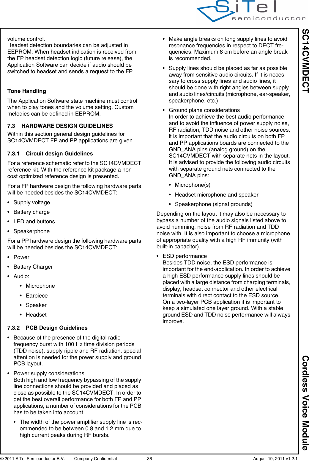
![SC14CVMDECT Cordless Voice Module© 2011 SiTel Semiconductor B.V. Company Confidential 35 August 19, 2011 v1.2.17.0 Design guidelinesThis section describes the software and hardware considerations taken into account when designing the target application. The SC14CVMDECT can be used standalone or next to an MCU that controls the module. In case the module is used standalone the application will be stored in its on-board Flash. In total 324kBytes of Flash are available for this.Applications can be written with the Athena software development environment (see [4]). 7.1 APPLICATION SOFTWARE FOR PP In a PP application the following software tasks must be handled by the MCU or within the module itself:• UART communication (external microprocessor only)• PP MMI• Display interface (optional)• Keyboard interface (optional)• Battery Charge interface (optional)• Audio handling• Tone / Melodies handlingFor control commands see document reference [1].UART communicationThe UART communication is the main control interface of the SC14CVMDECT.PP MMIThe MMI state machine must handle the call setup and call termination on the PP. Display InterfaceThe MCU / PP handles the display interface including the display driver.Keyboard InterfaceThe MCU/ PP handles the keyboard interface including the keyboard driver.Battery Charge handlingSC14CVMDECT V3 supports no battery management. This must be done by and external charge circuit on combination with the external MCU. The Application Software must handle the MMI part such as battery status for the user and the PP battery current consumption states.Audio handlingThe Application Software state machine must control when to open and close the audio. The headset plug-in detection must handled by the host, and a status is send to the PP MMI from the PP. The PP MMI must handle the volume control.Headset detection boundaries can be adjusted in EEPROM. When headset indication is received from the PP Headset detection logic (future release), the Application Software can decide if audio should be switched to the headset and sends a request to the SC14CVMDECT.The PP audio handling basically consists of 4 audio states (see Figure 9):1. Idle (Alert) State2. Earpiece State3. Handsfree State (Speakerphone)4. Headset StateShifting between states is done through the API.Please refer to the PP application layout for pin connections.Tone handlingThe Application Software state machine must control when to play tones and the volume setting. Custom melodies can be defined in the EEPROM.7.2 APPLICATION SOFTWARE FOR FP In an FP application the following software tasks must be handled by the MCU or within the module itself:• UART communication (external microprocessor only)•FP MMI• Display interface (optional)• Keyboard interface (optional)• Audio handling• Tone / Melodies handlingFor control commands see document reference [1].UART CommunicationThe UART communication forms the basic of the FP operation because via this interface the SC14CVMDECT is controlled.PP MMIThe MMI state machine must handle the call setup and call termination on the FP.Display InterfaceThe MCU/ FP handles the display interface including the display driver.Keyboard InterfaceThe MCU/ FP handles the keyboard interface including the keyboard driver.Audio HandlingThe Application Software state machine must control when to open and close the audio. The headset plug-in detection is handled by the FP, and a status is send to the FP MMI from the FP. The FP MMI must handle the](https://usermanual.wiki/Dialog-Semiconductor/SC14A.user-manual/User-Guide-1546287-Page-35.png)