Dialog Semiconductor SC14A DECT Cordless Voice Module User Manual SC14CVMDECTv1 2ls
Dialog Semiconductor BV DECT Cordless Voice Module SC14CVMDECTv1 2ls
Contents
- 1. user manual
- 2. user manual safety requirements
user manual
© 2011 SiTel Semiconductor B.V. Company Confidential 1
SC14CVMDECT Cordless Voice Module
DATASHEET
General description
The SC14CVMDECT is a member of the Cordless
Module family with integrated radio transceiver and
baseband in a single package. It is designed for hosted
and embedded cordless voice and data applications in
the DECT frequency band. Its simple to use
AT Commands set allows setting up of a wireless link
between 2 or more nodes without detailed knowledge
of the DECT protocol.
Features
nCompletely ETSI-certified
nETSI 300 444 (DECT GAP) compliant
nFCC approved
nSupports EU-DECT (CAT-iq V1 wideband audio),
DECT6.0 for North America and Japan DECT (pend-
ing approval)
nUp-to 6 portable parts registered per fixed part
nUART interface to external host
nControllable via AT command set (over UART)
nSupport voice and low speed data
nRF range: 1870 - 1930 MHz
nReceiver sensitivity < -93 dBm
nTransmit power 23 dBm (200 mW)
nAntenna’s included
nPower supply voltage 1.9 - 3.45V
nSmall form factor (25mm * 29mm)
nContains both PP and FP functionality
nProgram memory available for custom software.
Application Examples
nCordless Intercom
nCordless baby monitor
nWireless Data applications up to 1.6 Kbit/s.
________________________________________________________________________________________________
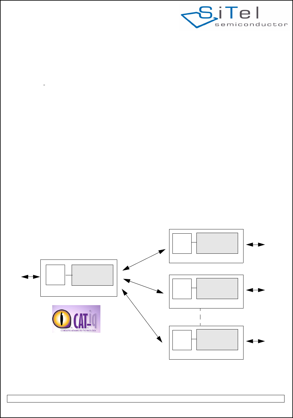
System Diagram
SC14CVMDECT
Fixed Part
Voice
Host
SC14CVMDECTHost
US/EU/JP*
DECT
Portable Part 0
Voice
SC14CVMDECTHost
Portable Part 1
Voice
SC14CVMDECTHost
Portable Part 5
Voice
Voice 32kbits/s
Data 1.6kbits/s
* Only end-products
can be CAT-iq certified
*
SC14CVMDECT
Cordless Voice Module
August 19, 2011 v1.2.1

SC14CVMDECT Cordless Voice Module
© 2011 SiTel Semiconductor B.V. Company Confidential 2 August 19, 2011 v1.2.1
Table of Contents
1.0 Connection Diagram . . . . . . . . . . . . . . . . . . . . . . . 3
1.1 PIN DESCRIPTION . . . . . . . . . . . . . . . . . . . . . . 3
2.0 Introduction . . . . . . . . . . . . . . . . . . . . . . . . . . . . . . 8
2.1 SCOPE . . . . . . . . . . . . . . . . . . . . . . . . . . . . . . . 8
2.2 ORDERING INFORMATION . . . . . . . . . . . . . . . 8
2.3 REFERENCES . . . . . . . . . . . . . . . . . . . . . . . . . 8
2.4 GLOSSARY AND DEFINITIONS . . . . . . . . . . . 8
3.0 Cordless Voice Module functionality . . . . . . . . . . 9
3.1 MODULE HARDWARE . . . . . . . . . . . . . . . . . . . 9
3.2 SOFTWARE CONTROL . . . . . . . . . . . . . . . . . . 9
3.3 DECT PROTOCOL STACK . . . . . . . . . . . . . . . 9
3.4 PORTABLE PART CONFIGURATION . . . . . 10
3.5 FIXED PART CONFIGURATION . . . . . . . . . . 12
3.6 LIGHT DATA APPLICATION . . . . . . . . . . . . . 14
3.7 FUNCTIONAL OVERVIEW . . . . . . . . . . . . . . . 15
4.0 Functional description. . . . . . . . . . . . . . . . . . . . . 16
4.1 UART INTERFACE . . . . . . . . . . . . . . . . . . . . . 16
4.2 EEPROM. . . . . . . . . . . . . . . . . . . . . . . . . . . . . 16
4.3 PP AUDIO CONFIGURATIONS . . . . . . . . . . . 17
4.4 CALL HANDLING . . . . . . . . . . . . . . . . . . . . . . 20
4.5 TONE/MELODY HANDLING. . . . . . . . . . . . . . 20
4.6 DATE AND REAL-TIME CLOCK . . . . . . . . . . 20
4.7 PROTOCOL STACK . . . . . . . . . . . . . . . . . . . 22
4.8 REGISTRATION . . . . . . . . . . . . . . . . . . . . . . 23
4.9 PCM INTERFACE . . . . . . . . . . . . . . . . . . . . . 24
5.0 CAT-iq . . . . . . . . . . . . . . . . . . . . . . . . . . . . . . . . . . 29
5.1 INTRODUCTION . . . . . . . . . . . . . . . . . . . . . . . 29
5.2 CAT-IQ PROFILE OVERVIEW . . . . . . . . . . . . 29
6.0 Specifications . . . . . . . . . . . . . . . . . . . . . . . . . . . . 30
6.1 ABSOLUTE MAXIMUM RATINGS . . . . . . . . . 30
6.2 DIGITAL INPUT LEVELS . . . . . . . . . . . . . . . . 31
6.3 DIGITAL OUTPUT LEVELS . . . . . . . . . . . . . . 31
6.4 LOUDSPEAKER LOAD CIRCUITS. . . . . . . . . 31
6.5 GENERAL SPECIFICATIONS . . . . . . . . . . . . 33
6.6 BASEBAND SPECIFICATIONS . . . . . . . . . . . 33
6.7 RADIO PART (RF) SPECIFICATIONS . . . . . . 33
6.8 FP POWER SUPPLY . . . . . . . . . . . . . . . . . . . 34
7.0 Design guidelines. . . . . . . . . . . . . . . . . . . . . . . . . 35
7.1 APPLICATION SOFTWARE FOR PP . . . . . . 35
7.2 APPLICATION SOFTWARE FOR FP . . . . . . 35
7.3 HARDWARE DESIGN GUIDELINES . . . . . . . 36
8.0 Audio Level Adjustment . . . . . . . . . . . . . . . . . . . 37
8.1 PP AUDIO LEVEL . . . . . . . . . . . . . . . . . . . . . . 37
8.2 FP AUDIO LEVEL) . . . . . . . . . . . . . . . . . . . . . 37
9.0 Example Application Diagram. . . . . . . . . . . . . . . 38
10.0 Mechanical Dimensions . . . . . . . . . . . . . . . . . . 39
11.0 Module integration . . . . . . . . . . . . . . . . . . . . . . . 40
11.1 MODULE PLACEMENT ON THE MAIN BOARD
40
12.0 UTAM membership waiver . . . . . . . . . . . . . . . . 41
13.0 Soldering. . . . . . . . . . . . . . . . . . . . . . . . . . . . . . . 42
13.1 SOLDERING PROFILE. . . . . . . . . . . . . . . . . 42
13.2 COPPER PAD AND SOLDER OPENING . . . 42
13.3 STENCIL . . . . . . . . . . . . . . . . . . . . . . . . . . . . 43
14.0 Notices to OEM. . . . . . . . . . . . . . . . . . . . . . . . . . 44
14.1 FCC REQUIREMENTS REGARDING THE END
PRODUCT AND THE END USER . . . . . . . . . 44
14.2 PRECAUTIONS REGARDING UNINTENDED
COUPLING . . . . . . . . . . . . . . . . . . . . . . . . . . . 44
14.3 END APPLICATION APPROVAL . . . . . . . . . 44
14.4 SAFETY REQUIREMENTS . . . . . . . . . . . . . . . . . 44
SC14CVMDECT Cordless Voice Module
© 2011 SiTel Semiconductor B.V. Company Confidential 3 August 19, 2011 v1.2.1
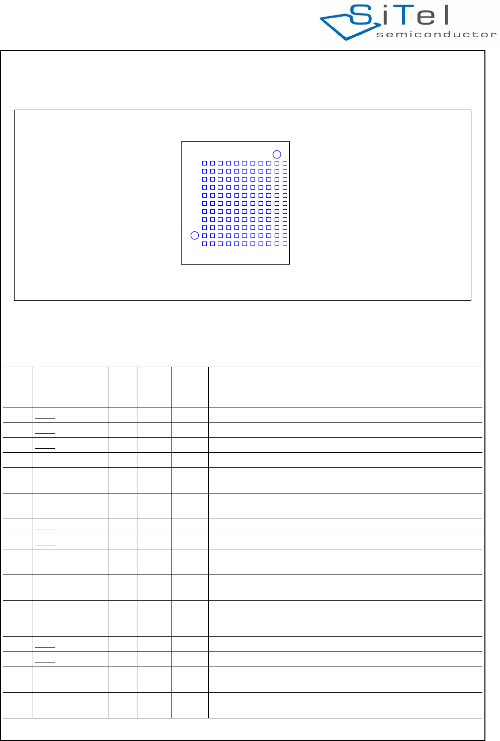
1.0 Connection Diagram
1.1 PIN DESCRIPTION
Figure 1 Connection Diagram (Bottom View)
M
L
K
J
H
G
F
E
D
C
B
A
121110 9 8 7 6 5 4 3 2 1
Table 1: Pin description
Pin Module
Pin name
In/
Out
Iout
Drive
(mA)
Reset
State Description
A1 GND -- -Ground
A2 GND -- -Ground
A3 GND -- -Ground
A4 NC - - I leave unconnected
A5 VDDIO I - - Supply voltage for internal QSPI and data flash. Must be connected
to VDD (1.8V).
A6 P1[2]/INT2 IO 2 I-PU I/O port.
INT2: Interrupt Input.
A7 GND -- -Ground
A8 GND -- -Ground
A9 VBAT I - - Main supply voltage <5.5V. Can be directly connected to a Li-Ion
battery.
A10 P0[4] / SPI_EN IO 8 I-PU I/O port
SPI_EN
A11 RSTn I 1 I-PU
(200k
pull-up)
Active low Reset input with Schmitt-trigger input, open-drain output
and pull up resistor to internal VDD. Input may not exceed 2.0 V. An
internal capacitor of 100nF is mounted on this pin.
B1 GND -- -Ground
B2 GND -- -Ground
B3 CP_VOUT1 O - I Charge Pump Output 1.
Must be connected through a capacitor of 1uF to gnd
B4 P1[5]/INT5 IO 8 O-1 I/O Port
INT5: Interrupt Input.
SC14CVMDECT Cordless Voice Module
© 2011 SiTel Semiconductor B.V. Company Confidential 4 August 19, 2011 v1.2.1
B5 GND -- -Ground
B6 P2[6]/INT6 /
WTF_IN
IO 2 I-PU I/O port
INT6: Interrupt Input.
WTF_IN: -
B7 P0[5] / SPI_CLK IO 8 I-PU I/O Port
SPI Clock
B8 GND -- -
B9 P0[1] / URX IO 8 I-PD
(10k)
I/O port
UART Serial In
B10 VBATT I - - Secondary supply voltage. Connect to VCCRF.
B11 GND -- -Ground
B12 NC - - - RF pad, no pad on PCB
C1 GND -- -Ground
C2 PAOUTn IO 500 O-0 (5k
fixed
pull-
down)
CLASSD loudspeaker positive output
C3 GND -- -Ground
C4 P2[7]/INT7 IO 8 I-PU I/O port
INT7: Interrupt
C5 P1[4]/INT4 IO 1/2 I-PD I/O port
INT4: Interrupt
C6 P1[1]/INT1 IO 2 I-PU I/O Port
INT1: Interrupt
LE: -
INT6: secondary Interrupt
C7 GND -- -Ground
C8 P0[0] / UTX O 8 I-PU I/O Port
UART Serial Out
C9 GND -- -Ground
C10 JTAG IO 8 I-PU JTAG-SDI+; one wire Debug interface with open-drain.
Pullup with R=1k to Vdd.
C11 VCCRF I - - RFSUPPLY input < 3.45V. Connect to VBAT if VBAT less than
3.45V. Else this pin must be supplied from and external 3.3V LDO.
Refer to Table 16 for supply requirements.
D1 GND -- -Ground
D2 PAOUTp IO 500 O-0 (5k
fixed
pull-
down)
CLASSD loudspeaker positive outputs
D3 PON I I (270k
fixed
pull-
down)
Power on, Switches on the device if Voltage > 1.5V.
May be directly connected to VBAT, also with Li-Ion batteries
Table 1: Pin description (Continued)
Pin Module
Pin name
In/
Out
Iout
Drive
(mA)
Reset
State Description
SC14CVMDECT Cordless Voice Module
© 2011 SiTel Semiconductor B.V. Company Confidential 5 August 19, 2011 v1.2.1
D4 CHARGE I - I-PD
(270k
fixed
pull-
down)
Charger connected indication. Switches on the device if voltage >
1.5v. Must be connected to charger via resistor R>(Vcharger_max-
3V)/10 mA (round to next largest value in range).
If no charger used, Leave unconnected if not used.
Charger is currently not supported.
D5 GND -- -Ground
D6 GND -- -Ground
D7 GND -- -Ground
D8 GND -- -Ground
D9 P2[4]/SCL1/
PCM_DO
IO 8 I-PU I/O port
SCL1; I2C clock
PCM_DO: PCM Data output
D10 VDD O - - Digital Core supply voltage (1.8V TYP).
Output from internal regulator.
D11 P2[5]/PCM_FSC IO 8 I-PU I/O Port
PCM_FSC: PCM Frame Sync
E1 VDDPA I - - CLASSD Audio Amplifier supply voltage up to 3.45V.
E2 GND -- -Ground
E3 CHARGE_CTRL O - O-0 Charge control pin.
Leave unconnected if not used.
Charger is currently not supported.
E4 SOCn I - I Battery State Of Charge negative input. Star point connected to the
SOC resistor.
Charger is currently not supported: connect to GND
E5 GND -- -Ground
E6 GND -- -Ground
E7 GND -- -Ground
E8 GND -- -Ground
E9 GND -- -Ground
E10 P0[7] / SPI_DI IO 8 I-PU I/O Port
SPI Data Input
E11 GND -- -Ground
F1 SOCp I - I Battery State of charge positive input.
Charger is currently not supported: connect to GND
F2 P1[0]/INT0/ADC1 IO 2 I-PU I/O Port
INT0: Interrupt 0
ADC1; ADC input 1
F3 ADC2/NTC I - I ADC2
NTC protection input for Li-Ion charger circuit.
Charger is currently not supported: connect to GND
F4 NC - - - leave unconnected
F5 ULP_PORT I - I Ultra Low Power Port Pin
Ultra low power is not supported by the software, connect to gnd.
F6 ULP_VBAT I - I Ultra Low Power Supply Pin
Ultra low power is not supported by the software, connect to gnd.
Table 1: Pin description (Continued)
Pin Module
Pin name
In/
Out
Iout
Drive
(mA)
Reset
State Description
SC14CVMDECT Cordless Voice Module
© 2011 SiTel Semiconductor B.V. Company Confidential 6 August 19, 2011 v1.2.1
F7 ULP_MAIN_CTR
L
- I-0 Ultra Low Power Main Control
Ultra low power is not supported by the software, connect to gnd.
F8 NC - - - RF pad, must be left unconnected
F9 P2[3]/SDA1 /
PCM_DI
IO 8 I-PU I/O Port
SDA1: I2C Data
PCM_DI: PCM Data input
F10 P1[3]/INT3 IO 1/2 I-PD I/O Port
INT3: Interrupt
F11 P0[6] / SPI_DO IO 8 I-PU I/O Port
SPI Data Out
G1 GND -- -Ground
G2 LSRn O - O Negative loudspeaker output
G3 GND -- -Ground
G4 P3[3]/ADC0 IO 8 I I/O Port
ADC0; ADC input 0
G5 GND -- -Ground
G6 NC - - - leave unconnected
G7 GND -- -Ground
G8 NC - - - leave unconnected
G9 GND -- -Ground
G10 GND -- -Ground
G11 GND -- -Ground
H1 VREFM - Negative microphone reference (star point), connect to gnd.
H2 LSRp O - O Positive loudspeaker output
H3 P3[7]/RINGp IO 4 I I/O Port
RINGp: Ringer detection input
H4 NC - - -
H5 GND - - I Ground
H6 GND - - I Ground
H7 P2[2]/PCM_CLK I/O 8 I-PD I/O Port
PCM_CLK: PCM clock input/output
H8 NC - - - RF pad, must be left unconnected
H9 GND -- -Ground
H10 GND -- -Ground
H11 GND -- -Ground
J1 GND -- -Ground
J2 MICh I - I Headset microphone input with fixed input protection
J3 GND -- -Ground
J4 P3[5]/RINGING /
RINGOUT
IO 4 I I/O Port
RINGING: Ring detection Input
RINGOUT: -
J5 GND -- -Ground
J6 NC - - - RF pad, must be left unconnected
Table 1: Pin description (Continued)
Pin Module
Pin name
In/
Out
Iout
Drive
(mA)
Reset
State Description
SC14CVMDECT Cordless Voice Module
© 2011 SiTel Semiconductor B.V. Company Confidential 7 August 19, 2011 v1.2.1
• “NC” means: leave unconnected.
•GND means internally connected to Ground plane of
module (51 pins in total)
• GND means connect to Ground (not supported,
functional pin)
Reset States:
• I = Input
• O= Output
• I-PD = Input, pulled down
• I-PU = Input, pulled up
• O-0 = Output, low
• O-1 = Output, high
J7 GND -- -Ground
J8 P2[1] / PWM1 /
LED4
IO 8 I I/O Port
PWM1: Pulse Width Modulation output
LED4: 2.5/5mA LED current sink
J9 GND -- -Ground
J10 GND -- -Ground
J11 GND -- -Ground
K1 VREFp O - I Positive microphone supply voltage
K2 MICp I - I Positive microphone input
K3 P3[2]/CIDINp IO 8 I I/O Port
CIDINp: Caller id opamps positive input
K4 P3[6]/RINGn IO 3 I I/O Port
RINGn: RING opamp negative input
K5 P3[4]/PARADET IO 8 I I/O Port
PARADET: Parallel set detection
K6 NC - - - leave unconnected
K7 NC - - - leave unconnected
K8 P2[0]/ PWM0 /
LED3
IO 8 I I/O Port
PWM0: -
LED3: 2.5/5mA LED current sink
K9 GND -- -Ground
K10 NC - - - No ground under the pad (RF sensitive)
K11 NC - - - No ground under the pad (RF sensitive)
L1 GND -- -Ground
L2 MICn I - I Negative handset microphone input
L3 GND -- -Ground
L4 GND -- -Ground
L5 NC - - - RF pad, must be left unconnected
L6 GND -- -Ground
L7 GND -- -Ground
L8 NC - - - leave unconnected
L9 GND -- -Ground
L10 NC - - - No ground under the pad (RF sensitive)
L11 GND -- -Ground
M2 NC - - - RF pad, no pad on PCB
Table 1: Pin description (Continued)
Pin Module
Pin name
In/
Out
Iout
Drive
(mA)
Reset
State Description

SC14CVMDECT Cordless Voice Module
© 2011 SiTel Semiconductor B.V. Company Confidential 8 August 19, 2011 v1.2.1
2.0 Introduction
2.1 SCOPE
The SC14CVMDECT is a programmable DECT
module for voice and low data rate services. The
internal software-stack receives commands and data
from the application, for instance to setup a link to
other modules. The user interface can be implemented
on the module itself or on anexternal host processor.
The internal FLASH provides user space where
custom applications can be located. The module
converts analog signals to a digital stream,
compresses/decompresses them according to the
DECT standards and transmits/receives them over the
air interface. The DECT protocol-stack in each module
supports both PP and FP functionality.
2.2 ORDERING INFORMATION
SC14CVMDECT AF01
2.3 REFERENCES
1. SC14CVMDECT AT Commands
2. SC14CVMDECT AT Commands
Communication Library
3. SC14CVMDECT_PC_MMI_User_Guide
4. Athena User Manual
2.4 GLOSSARY AND DEFINITIONS
API Application Programming Interface
AT Command Interface
The software interface between the
MCU and SC14CVMDECT
CAT iq Cordless Advanced Technology, Internet
and Quality
Codec Coder and DeCoder converts analog
signals to digital signals and vice versa.
Conference Same as intercom, but generally
including an external party.
CRC Cyclic Redundancy Check
CVM Cordless Voice Module
DECT Digital Enhanced Cordless Telephone
DSP Digital Signal Processor
EC Echo Canceller
EMC Equipment Manufacturer’s Code (please
refer to ETSI EN 300 175-6)
ESD Electro Static Discharge
EQ Equalizer
FP Fixed Part
GFSK Gaussian Frequency Shift Keying
HW Hardware
Inband tones Tones played by the application itself
and not from external e.g. line.
Intercom Internal call between 2 or more parties.
IPEI International Portable Equipment Identity
(please refer to ETSI EN 300 175-6)
IWU InterWorking Unit (please refer to ETSI
EN 300 175-1)
LCD Liquid Crystal Display
LDR Low Data Rate
MCU Micro Controller Unit
MMI Man Machine Interface (keypad, LCD,
buzzer, microphone, earpiece, speaker,
headset)
NTP Nominal Transmit Power
PAEC Perceptual Acoustic Echo Canceller
PC Personal Computer, IBM compatible
PCB Printed Circuit Board without
components
PP Portable Part
PSTN Public Switched Telephone Network
POTS Plain Old Telephone System
RF Radio Frequency
RFPI Radio Fixed Part Identity (please refer to
ETSI EN 300 175-6)
RLR Receive Loudness Rating
RSSI Radio Signal Strength Indication (please
refer to ETSI EN 300 175-1)
Sidetone Feedback of microphone signal to
earpiece.
SLR Sending Loudness Rating
SPI Serial Periphelal Interface Bus
SW Software
UART Universal Asynchronous Receiver and
Transmitter.
VAD Voice Activity Detection
Walky Talky Two PPs connected without an FP
SC14CVMDECT Cordless Voice Module
© 2011 SiTel Semiconductor B.V. Company Confidential 9 August 19, 2011 v1.2.1
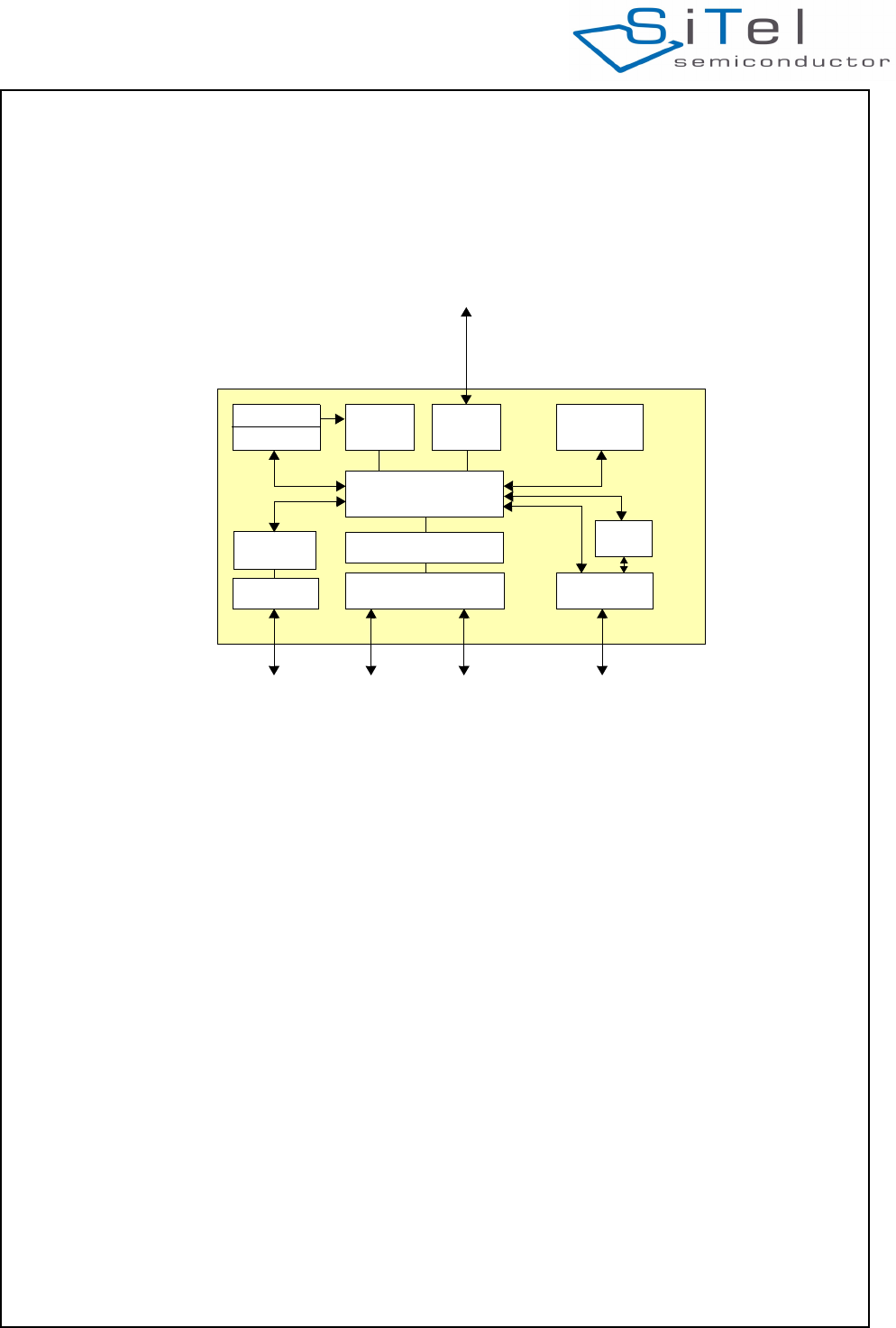
3.0 Cordless Voice Module
functionality
This section describes the key functions and features
supported by the SC14CVMDECT as shown in Figure
2.
3.1 MODULE HARDWARE
The SC14CVMDECT internal hardware consist of:
• An Internal Microprocessor (MCU) running from
FLASH handling the AT command interpreter, the
protocol stack and further internal control.
• A 4kByte EEPROM used by the protocol stack and
for user EEPROM variables.
• A DSP for the Audio signal processing like ADPCM
voice compression towards the Codecs.
• A codec to convert the analog signals to digital
signals and vise versa.
• Input/Output ports which can be toggled high/low if
output or a high/low digital level can be read.
• A 10.368 MHz XTAL clock. This crystal is
automatically tuned by the module software for the
best Radio Performance.
• Voltage regulators to convert the external supply
voltage to a stable supply voltages for the core and
I/O’s.
• A DECT Radio transceiver with two built-in antenna
circuits. The antenna’s are on the module, so no RF
knowledge is required.
• A UART for communication to a host.
3.2 SOFTWARE CONTROL
The SC14CVMDECT can be controlled via an AT
Command Set over the UART interface or from the
internal user application. The external controller
handles the user interface (MMI) and sends/receives
AT commands and responses to the internal protocol
stack. A detailed functional and data flow description,
including an example of the start-up sequence, can be
found in document reference [1].
3.3 DECT PROTOCOL STACK
The SC14CVMDECT internal protocol stack is based
on the ETSI DECT specifications and is compliant with
ETSI 300 444 (GAP).
The product supports up to 6 DECT GAP compliant PP
units to one FP station.
Figure 2 SC14CVMDECT functional overview
UART interface
to host
AT commands
AT command
interpreter
Radio
Protocol
Stack DSP
Ports
DECT
EEPROM XTAL
FLASH
Codec
User
MIC
LSR
Headset Control
UART
SW
SPI
SC14CVMDECT Cordless Voice Module
© 2011 SiTel Semiconductor B.V. Company Confidential 10 August 19, 2011 v1.2.1
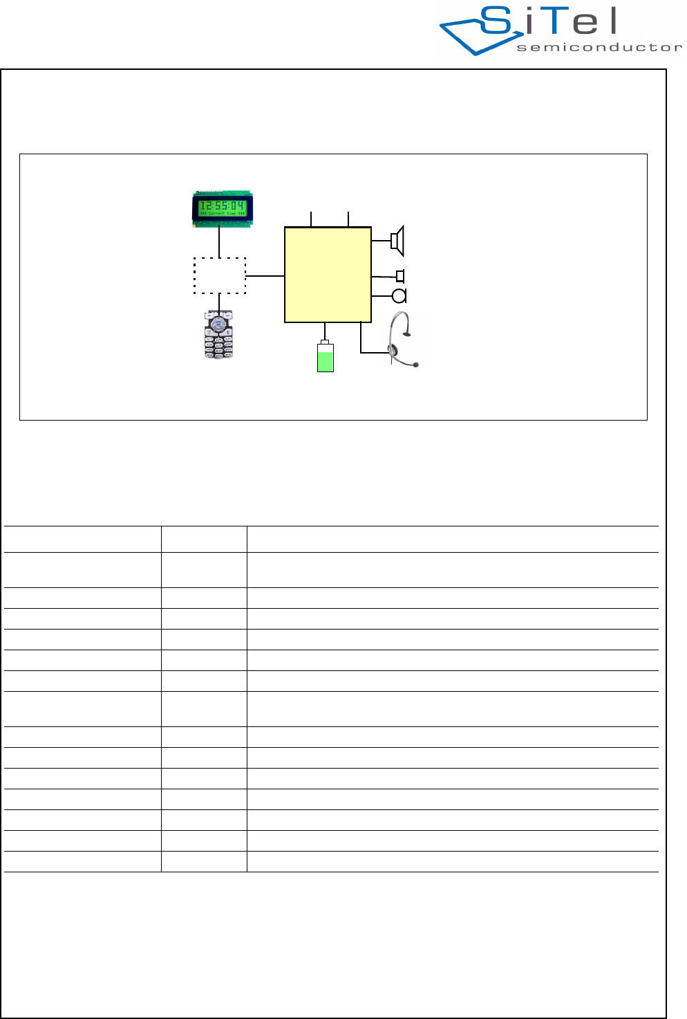
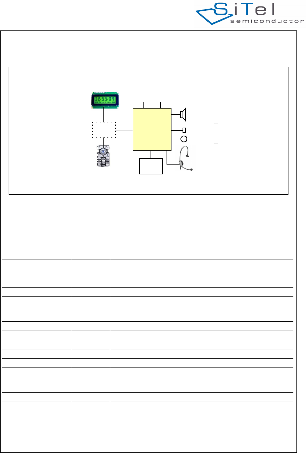
3.4 PORTABLE PART CONFIGURATION
A Portable Part configuration with SC14CVMDECT
requires additional external parts as shown in Figure 3. .
Table 2 provides the overview of the supported
interfaces for a Portal Part.
A portable part supports following main functional
features:
•Conferencing (currently not supported*)
•Intercom
•Battery management (currently not supported*)
•Custom Ringtones (currently not supported*)
•Earpiece, handsfree and headset.
•Automatic headset detection (currently not
supported*)
•Baby monitor (currently no VAD support*)
Figure 3 PP Configurations
SC14CVMDECT
(optional)
(optional)
Loudspeaker
MIC2
Earpiece
MCU (handset speaker)
Headset
UART
Ports PCM
(optional)
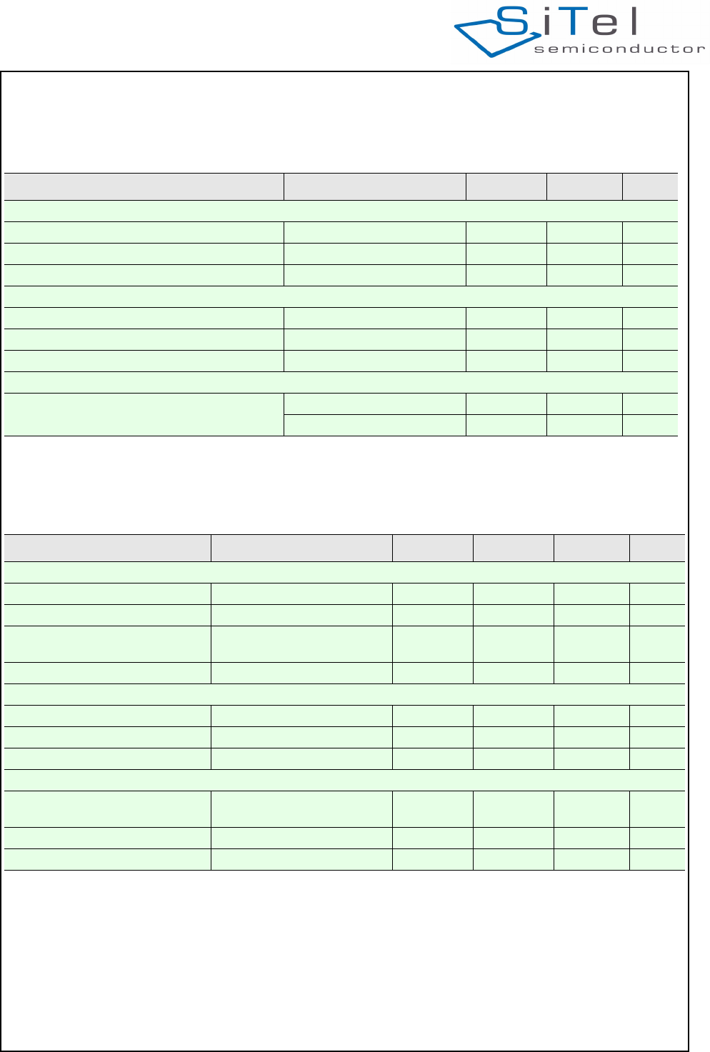
Table 2: PP Hardware support overview
Item Supported Remark
Battery connection No Non rechargeable or rechargeable 2 cells NiMH, NiCd or Li-Ion
For Li-Ion an 3.3V LDO is required to supply the system.
Battery charger No Use external charger.
Keypad No on external MCU
Display No on external MCU
IO Ports Yes 4 free digital IO port pins
PCM interface Yes 1x16 bits, 8,16 kHz, strobes 1,8, 16, 32 bits
PCM voice coding
formats
Yes uLaw (64kbits/s), Alaw (64kbits/s), G.726 ADPCM (32kbits/s), G.722
ADPCM (64kbits/s), Linear (128kbits/s)
UART Yes 9600-115.2kbaud, used for AT-command
Headset detection Yes
Headset earpiece Yes Connected to LSRp,LSRn
Headset Microphone Yes Connected to MICp
Handsfree Microphone Yes Connected to MICh
Handsfree speaker Yes Connected to PAOUTP/n (No SW support)
Radio Yes Integrated with two antenna’s

SC14CVMDECT Cordless Voice Module
© 2011 SiTel Semiconductor B.V. Company Confidential 11 August 19, 2011 v1.2.1
•PCM interface (one channel)
•Walky Talky mode (currently not supported*)
•Low Speed Data (1.6kbit)
•LU10 data channel (54kbit/sec) (Currently not
supported*)
* Expected in Q2 2012
SC14CVMDECT Cordless Voice Module
© 2011 SiTel Semiconductor B.V. Company Confidential 12 August 19, 2011 v1.2.1
3.5 FIXED PART CONFIGURATION
A Fixed Part configuration with SC14CVMDECT
requires additional external parts as shown in Figure 4. .
Table 3 provides the overview of required and
available interfaces for a basic or a feature rich
cordless FP with the SC14CVMDECT. .
A fixed part supports following main functional
features:
•Conferencing (currently not supported*)
•Intercom
•Custom Ringtones (currently not supported*)
•Earpiece, handsfree and headset.
•Automatic headset detection (currently not
supported*)
Figure 4 FP Configuration
SC14CVMDECT
(supported in future versions)
(optional)
Loudspeaker
MIC2
Earpiece
MCU (handset speaker)
Supply
Ports
Headset
Regulator
PCM
Analog frontend
can be used for
PSTN line interface
UART
(optional)
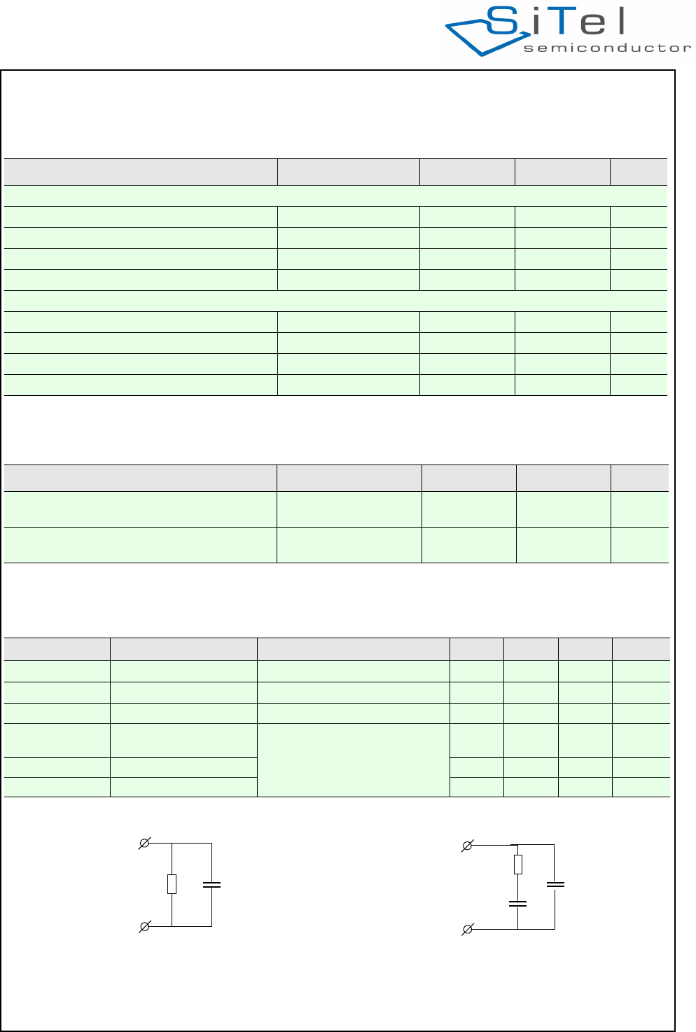
Table 3: FP Hardware support overview
Item Supported Remark
Supply Regulator No Use external 3.3V LDO.
Keypad No on external MCU
Display No on external MCU
IO Ports Yes 4 free port pins
PCM interface Yes 4x16 bits, 8,16 kHz, strobes 1,8, 16, 32 bits
PCM voice coding
formats
Yes uLaw (64kbits/s), Alaw (64kbits/s), G.726 ADPCM (32kbits/s), G.722
ADPCM (64kbits/s), Linear (128kbits/s)
UART Yes 9600-115.2kbaud, used for AT-command
Headset detection Yes
Headset earpiece Yes Connected to LSRp,LSRn
Headset Microphone Yes Connected to MICp
Handsfree Microphone Yes Connected to MICh
Handsfree speaker Yes Connected to PAOUTP/n (No SW support)
PSTN Line interface Yes CID, Ring detection, Line-in, Linout, Line reversal, paralle set detection
(SW On request)
Radio Yes Integrated with two antenna’s

SC14CVMDECT Cordless Voice Module
© 2011 SiTel Semiconductor B.V. Company Confidential 13 August 19, 2011 v1.2.1
•Baby Monitor (currently not supported*)
•PCM interface (4 channels)
•Low Speed Data (1.6kbit)
•LU10 data channel (54kbit/sec) (Currently not
supported*)
•Base Station For Sensor applications (Currently not
supported*)
* Expected in Q2 2012
SC14CVMDECT Cordless Voice Module
© 2011 SiTel Semiconductor B.V. Company Confidential 14 August 19, 2011 v1.2.1
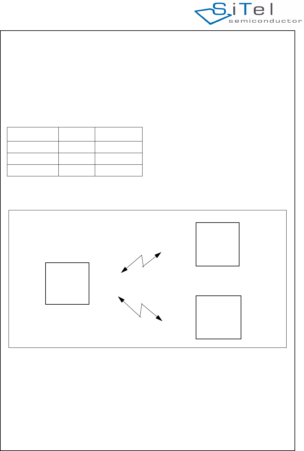
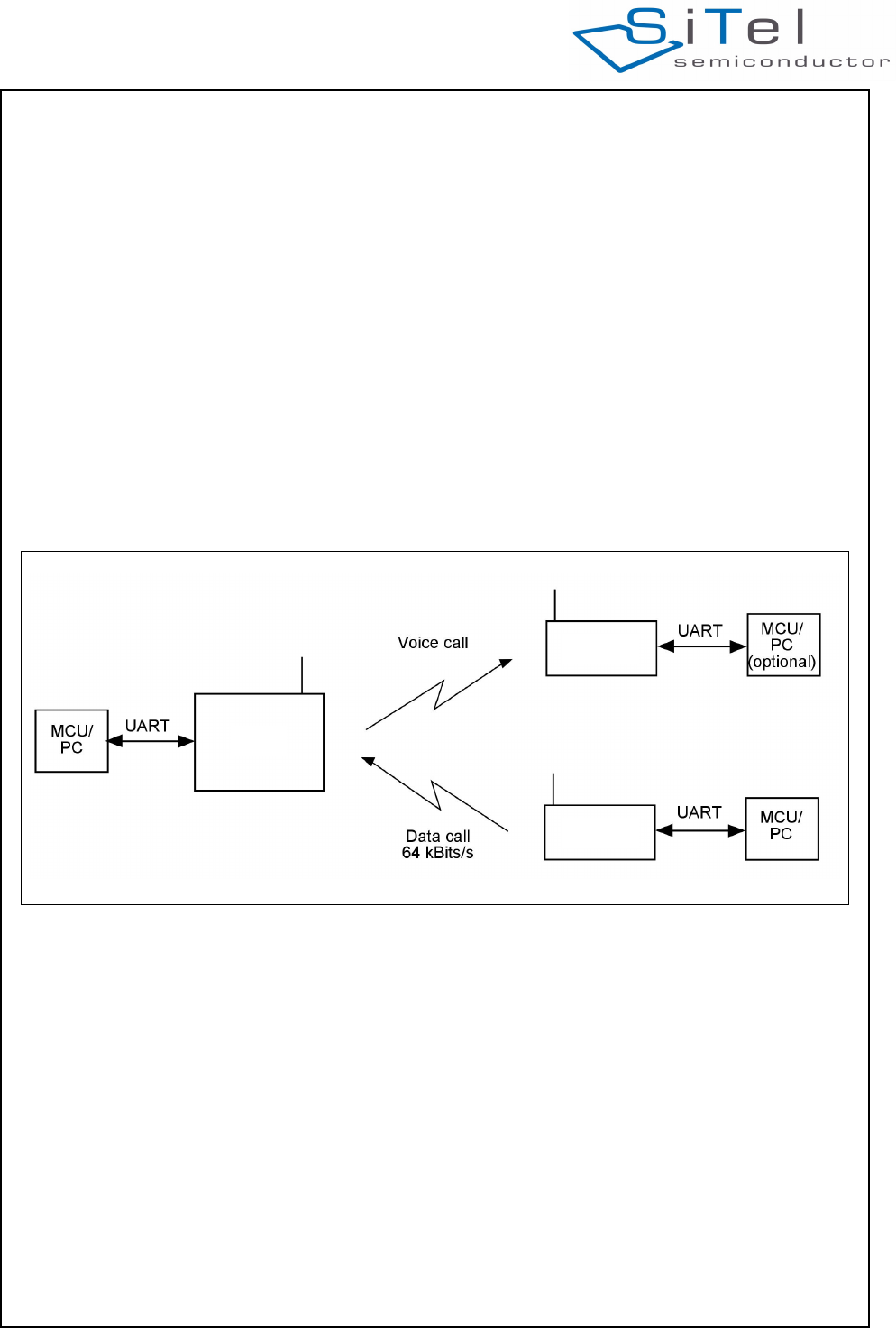
3.6 LIGHT DATA APPLICATION
The SC14CVMDECT supports Low Data Rate (LDR)
transmission up to 1.6 kbits/s. Packets with a length of
upto 30 bytes payload can be transmitted and
received.
One SC14CVMDECT is configured as FP and the
others are configured as PPs (Figure 5). The host
sends/receives AT commands (over UART) to/from PP
or FP as shown in Table 4.
Up to six PPs can be registered to one FP.
See document reference [1] for more information on
the AT commands to support LDR.
Table 4: Low Data Services
Direction Supported Comment
Host to PP to FP Yes
Host to FP to PP Yes
PP to PP Yes Indirect via FP
Figure 5 Light Data application
1.6 kbits/s
1.6 kbits/s
SC14CVMDECT
SC14CVMDECT
SC14CVMDECT
PP
FP
PP
SC14CVMDECT Cordless Voice Module
© 2011 SiTel Semiconductor B.V. Company Confidential 15 August 19, 2011 v1.2.1
3.7 FUNCTIONAL OVERVIEW
Table 5: Functional overview
Functionality Sup-
ported Remark
Standard FP audio control feature: Call handling
PP to FP, FP to PP Yes
Intercom No PP to FP, FP to PP
Conference call No
Call forwarding No Transfer call between PPs not possible.
Page call Yes FP pages all PPs (PP locator)
Protocol
Manual registration Yes
Number of registered PPs per FP Yes 1 to 6
Low rate data transfer Yes 1.6 Kbit/s on the air-interface (30 bytes payload)
Audio and tone
Microphone mute Yes PP only. Mute of MIC in all audio connections are possible
Tone generation Yes Melody generator with 7 polyphonic tones
Audio Volume control Yes 6 steps are adjustable by EEPROM
Tone Volume control Yes 6 steps are adjustable by EEPROM
Headset support Yes
Handsfree/Speakerphone Yes PP only
General
Real time clock Yes Accuracy depending directly on crystal
Real time clock synchronization Yes All PP clocks are kept in synchronization with the FP
SW EEPROM Storage Yes Internal on Module
Battery Charge Management No
PSTN line interface support No PSTN software on Request
I/O port support Yes 4 pins I/O
Port Interrupt support No
SC14CVMDECT Cordless Voice Module
© 2011 SiTel Semiconductor B.V. Company Confidential 16 August 19, 2011 v1.2.1
4.0 Functional description
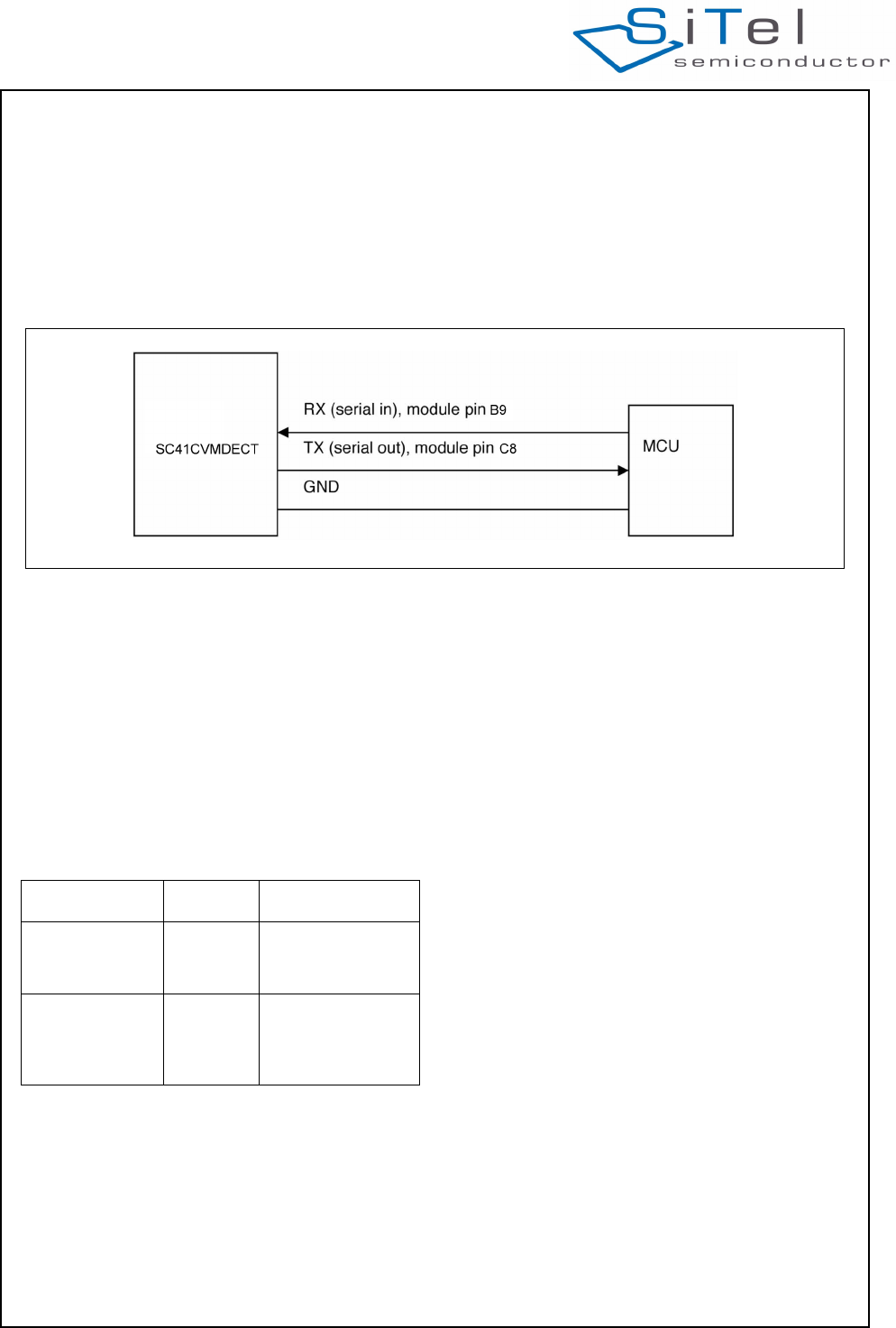
4.1 UART INTERFACE
The UART isnormally used for AT commands, but can
also be used for software upgrades and debugging.
The UART is a full duplex UART with frame type: 1
start bit, 8 data bits (LSB first), 1 stop bit, no parity and
a baud rate of 115.200 kBaud
The UART hardware interface uses 3 wires
(see Figure 6) .
Caution: All signals are 1.8 V. An external V.24 line
driver must be provided if the UART port of the module
is connected to a standard V.24 device. Connecting
the module without a driver may damage the module.
4.2 EEPROM
4.2.1 EEPROM layout
The SC14CVMDECT PP and FP include a 4 Kbyte
EEPROM which is divided into two areas (see Table
6).
A detailed overview of the EEPROM parameter is
found in document reference [2].
Some parts of the EEPROM parameters are read into
the SC14CVMDECT during the start up and other parts
are used by the SC14CVMDECT software during
execution.
The EEPROM parameters are divided into 2 types:
• Factory type
• normal type.
The factory type is specific for the SC14CVMDECT
and should only be set by production. The factory types
are either parameters for adjustments used by the
baseband or the radio interface, or is used to setup the
SC14CVMDECT into special modes. The factory types
will only be modified by changing the factory
programmed default value. See document reference
[2]. Only users with “debug” authorization can modify
these EEPROM parameters
The other “normal” EEPROM parameters can be reset
to default values by running a soft default setting
(default batch file).
4.2.2 EEPROM access by MCU
The host is able to read or modify the EEPROM
parameters or limited free EEPROM areas via AT
commands AT+WEExx.
Access to the EEPROM parameters depends on the
authorization level set by the AT+WULA parameter:
0 = Anonymous User with Lowest Authority (not able to
read from and write to EEPROM)
1 = Power User. Able to read from all EEPROM
locations and write to locations 0x0F00..0x0FBF (user
space). Password: 748357.
2 = Debug User Highest Authority.Able to read from
and write to EEPROM (audio and stack related
parameters. Contact SiTel Semiconductor for the
password.
Figure 6 UART hardware configuration
Table 6: EEPROM map
EEPROM space Size Usage
SC14CVMDECT 3.6 Kbyte Used for RF, audio,
battery, tone setup,
data base, etc.
User 0.4 Kbyte. Can be used for
MMI applications
such as User
information.
SC14CVMDECT Cordless Voice Module
© 2011 SiTel Semiconductor B.V. Company Confidential 17 August 19, 2011 v1.2.1
4.3 PP AUDIO CONFIGURATIONS
The SC14CVMDECT audio is supporting standard
DECT audio qualities. The audio gain and volume
parameters are placed in the EEPROM. The DECT
gains can be adjusted to meet the TBR38 and TBR10
audio level requirements by using the SC14CVMDECT
application reference design. For other line and
acoustic designs it is needed to adjust and tune the
audio setup.
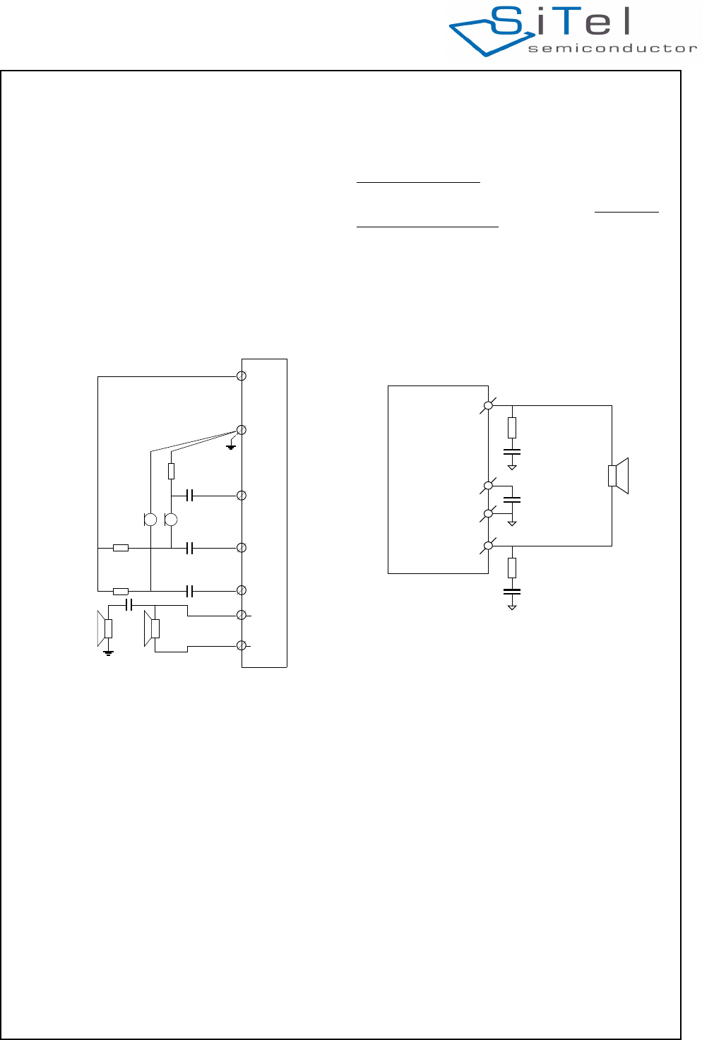
4.3.1 Audio connection
The SC14CVMDECT PP audio connections are show
in Figure 7. Refer to “Example Application Diagram” on
page 38 for detailed component values.
.
Earpiece or small loudspeaker connection
The earpiece loudspeaker can be connected either
differentially or single-ended. Dynamic loudspeakers
with an impedance of 30 can be connected as well
as ceramic loudspeakers equivalent to 600 and
30 F can be connected. Refer to Table 11 for a
detailed specification or the earpiece loudspeakers.
The earpiece is connected to the LSRp and LSRn pins.
Microphone connection
The microphone can be connected either single-ended
via MICp or differentially to MICp and MICn
Headset connection
The headset microphone must be connected to the
MICh pin. The headset earpiece is connected to the
LSRp.
Microphone supply connection
For active microphones a voltage source with high
supply voltage rejection ratio is provided on supply pins
VREFp/VREFm. Filtering of internal and external
reference voltages is provided with internal capacitor.
No external capacitor shall be connected to the
VREFp. To avoid audible switching noise it is important
that the ground supply signals are directly “star point”
connected to the VREFm and not via a common
ground plane. From this VREFm star point, one
connection is made to the common ground plane.
Loudspeaker connection (supported in future
releases)
For the handsfree operation an 4 ohm loudspeaker
must be connected to the PAOUTp and PAOUTn pins
as shown in Figure 8. The VDDPA is the supply pin.
Refer to Table 12 for a detailed specification of the
external components around the loudspeaker. These
components are necessary to guarantee lifetime of the
module.
Figure 7 Audio connections
LSRn
LSRp
MICh
MICn
VREFm
MICp
VREFp
Figure 8 Loudspeaker connection
PAOUTp
PAOUTn
VDDPA
VSS/GND
C_VDDPA
Cs_PAOUT
Rs_PAOUT
Cs_PAOUT
Rs_PAOUT
SC14CVMDECT Cordless Voice Module
© 2011 SiTel Semiconductor B.V. Company Confidential 18 August 19, 2011 v1.2.1
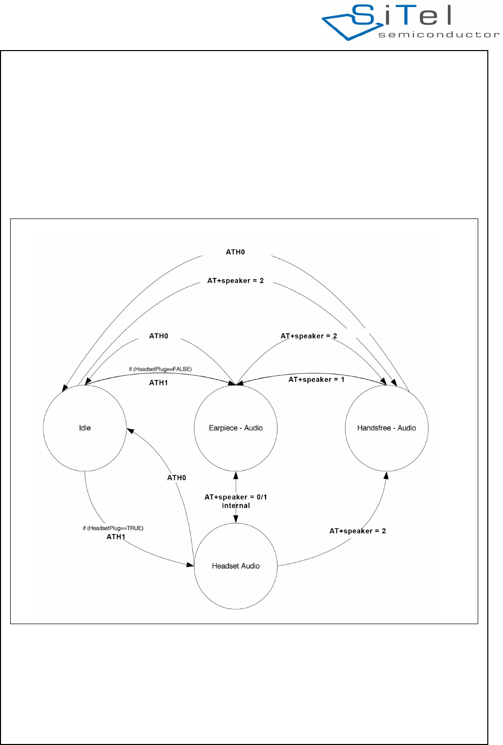
4.3.2 Audio Modes
The PP audio handling consists of four audio states. In
these states the audio subsystem is configured for a
certain audio mode:
1. Idle state (not relevant for microphone
configuration)
2. Earpiece Mode (Handset Speaker)
3. Handsfree or Speakerphone Mode
4. Headset mode
Selection between the modes is done by API calls; see
document reference [1].
The Alert state is for tone playing and is entered
automatically when tones are played using the API
calls. The Alert state can originate from idle earpiece,
handsfree or headset state
.
Figure 9 PP Audio mode
SC14CVMDECT Cordless Voice Module
© 2011 SiTel Semiconductor B.V. Company Confidential 19 August 19, 2011 v1.2.1
4.3.3 PP Audio Codec adjustment
The audio codec settings for the loudspeaker and
Microphone must be preconfigured in the EEPROM for
each mode. The EEPROM parameter fields for
Audio.Earp.xxx, the Audio.Heads.xxx and
Audio.SpkPh.xxx have a default value but may be
modified to tune the settings.
4.3.4 General Audio adjustment
For each audio mode, the receive (RLR) and transmit
(SLR) audio paths must be adjusted. RLR and SLR are
adjusted in the registers in the EEPROM for each
audio state; see document reference [2].
4.3.5 Power management
To minimize the current consumption the PP will
shutdown all codec amplifiers in Idle state. This means
that all reference voltages in the front-end will be
disabled. This feature can be disabled in the EEPROM
if the reference voltages for some reasons are needed
in Idle state.
4.3.6 Earpiece Mode
In Earpiece mode (Handset Speaker) an artificial
sidetone is generated. The level of the sidetone can be
adjusted and setup in the EEPROM through parameter
fields Audio.Earp.Vol.Elementx,SideToneGain and
Audio.Heads.Elementx.SideToneGain. In Earpiece
mode it is possible to adjust the volume in the Earpiece
via the API calls. In Earpiece mode the PP audio is
routed as shown in Figure 11.
4.3.7 Alert mode
The Alert mode is for generating tone and melodies in
the Speakerphone loudspeaker. In Alert mode it is
possible to adjust the volume in the speaker via the
API calls.
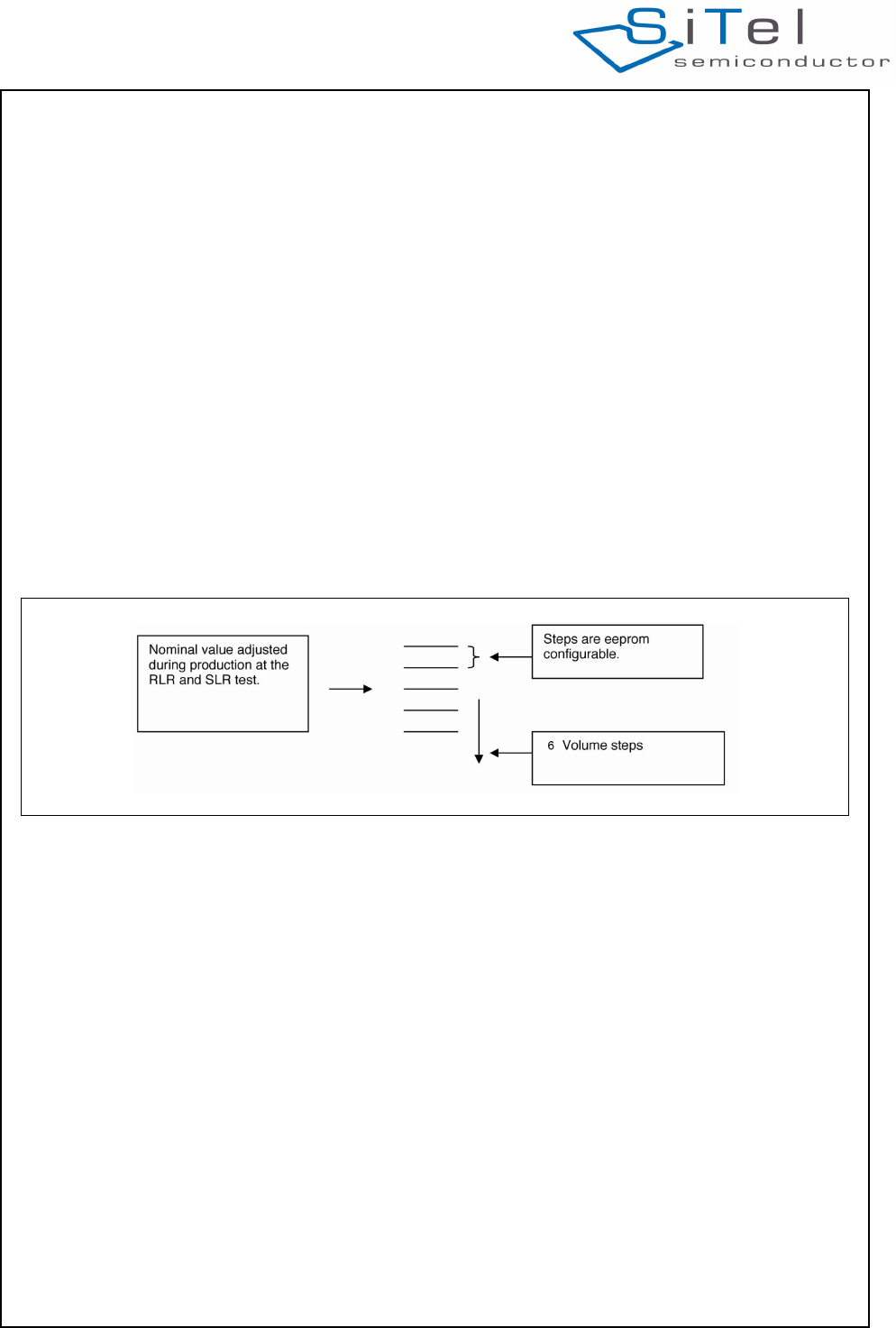
4.3.8 PP Volume
The PP supports 6 volume steps, which are EEPROM
configurable through parameter fields
Audio.Earp.Vol.xxx, the Audio.Heads.Vol.xxx and
Audio.SpkPh.Vol.xxx. The volume steps must be set
initially in the EEPROM during production.
.
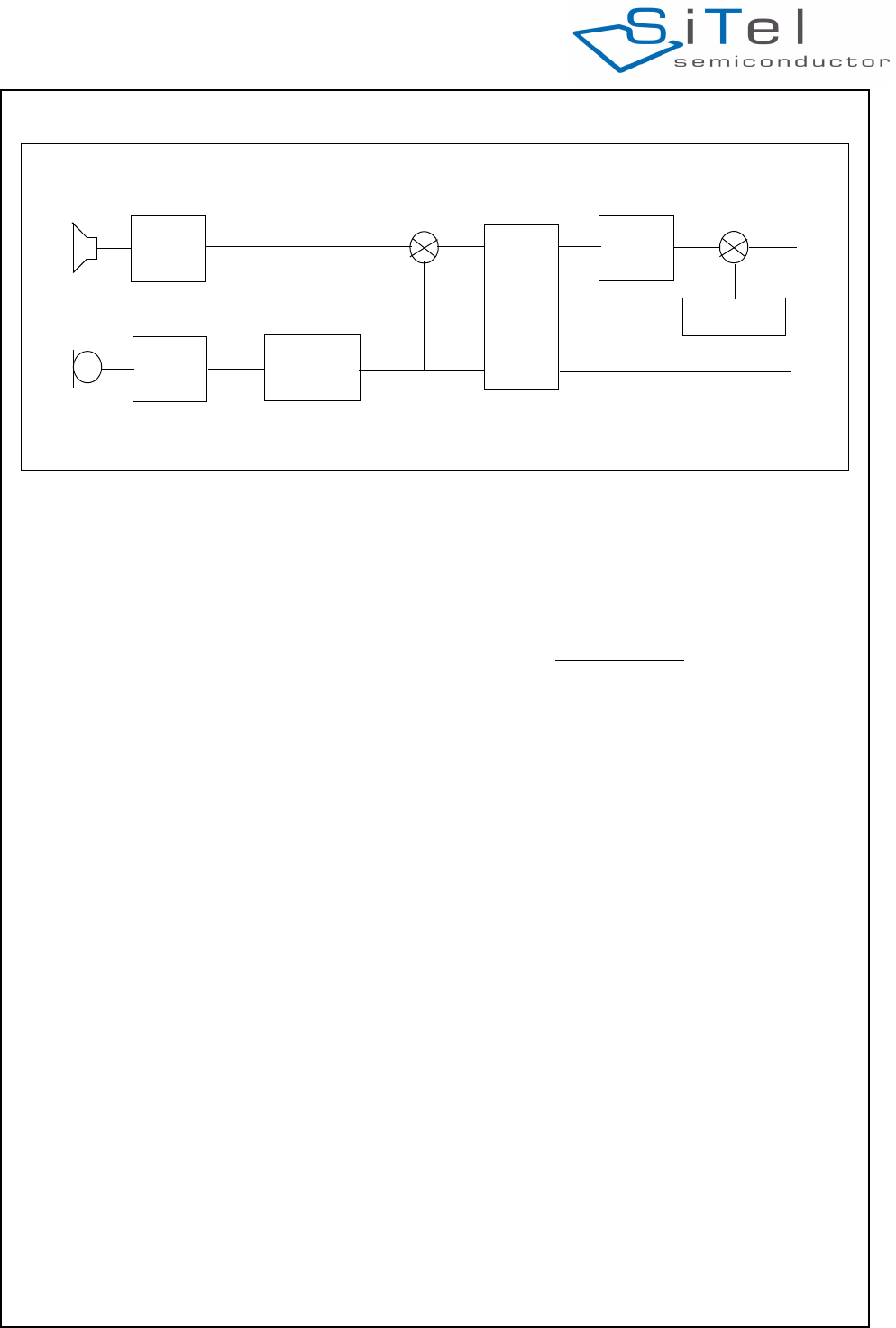
Inband tones will be affected by the volume
adjustments, since the volume control is placed after
tones are added to the signal..Figure 11 shows the
Audio flow. Here is the list of main functions:
EQ Equalizer
nc100Hz 100Hz canceller
Sidetone Sidetone
EC Echo Canceller
Vol. Ctrl Volume Control
Tonegen Tone generator
Figure 10 Handset Volume Configuration
SC14CVMDECT Cordless Voice Module
© 2011 SiTel Semiconductor B.V. Company Confidential 20 August 19, 2011 v1.2.1
.
4.3.9 PP Audio equalization
To enable adjustments of the frequency response the
PP contains four programmable filters: 2 in RX
direction and 2 in TX direction (see Figure 11).
By default these filters are loaded with bypass
coefficients, but the API contains commands to load
new coefficient for all filters.
Equalizer filters are part of the audio routes for all
audio modes and are placed as shown in Figure 11.
For a detailed description of the filter functionality
please refer to API documentation; see document
reference [1].
4.4 CALL HANDLING
4.4.1 FP to PP Call
When the FP initializes a call to a PP, a radio
connection is set up to all the PP applications to make
it possible for the PP Application Software to indicate
that there is an incoming call.
It is possible to configure the ringing indication using
broadcast to make all 6 PPs ringing. When receiving
the call, the PP signals the call to the MMI Software.
4.4.2 PP to FP Call
When the MMI Software signals the PP to establish a
call, the PP opens the radio connection to the FP.
4.4.3 Intercom and Conference
Not supported.
4.4.4 Call Transfer
Call transfers are not supported.
4.4.5 Page Call
The Page call is a FP functionality used to locate the
registered PPs. FP paging does not establish a normal
audio connection and is terminated when answered by
the PP. In FP Speakerphone mode a voice call can be
established when the paging is answered.
4.4.6 Connection scenarios
The following voice connections are supported.
• PP to FP
• FP to PP.
4.5 TONE/MELODY HANDLING
The tone component handles the generation of various
tones in the device. Both tones/melodies in a FP and
PP configuration are supported. Main features of the
tone component are:
The main features of the tone component are:
• Ringer tones and melodies (7 tone polyphonic)
• Alert tones (key sound, error tones, confirmation
tones, etc.)
• Inband tones (dial tone, net-congestion tone, busy
tone, etc.)
• Single tone generation
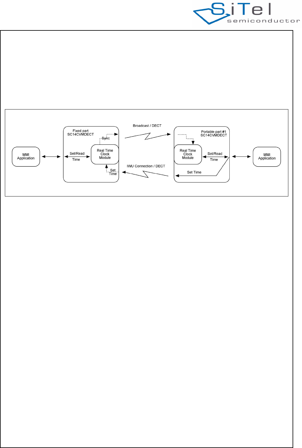
4.6 DATE AND REAL-TIME CLOCK
The FP base has a real-time clock feature, which
(when activated) broadcasts the date and clock to the
PPs. Activation of the date and real-time clock is done
by setting the date and clock via the PP.
The clock is with hours, minutes and date. The clock
supports the leap year. Daylight saving is not
supported and must be handled by the MMI
application.
The PP clock is synchronized with the FP every time a
broadcast is received. If the PP goes out-of-lock, the
PP itself calculates the clock until the PP is again
within the range of the FP. The updated clock can then
Figure 11 PP Audio Routing
EQ
EQ nc100Hz
EC
Vol.
ctrl
tonegen
Rx_in
Tx_out
Sidetone
SC14CVMDECT Cordless Voice Module
© 2011 SiTel Semiconductor B.V. Company Confidential 21 August 19, 2011 v1.2.1
be read locally from the MMI Software.
To adjust the clock in the base station, a service
connection can be setup which can be set by
commands from the PP.
The clock can also be read and set directly from an
external microprocessor or through the MMI software
on the FP base.
The real-time clock accuracy depends directly on the
SC14CVMDECT crystal.
When the SC14CVMDECT is configured as a PP, the
clock has the same accuracy as the FP clock. But,
when the PP synchronises with a FP, the PP crystal is
synchronized with the FP crystal and the PP clock will
change accordingly.
The accuracy is expected to be within 1 minute for up
to 6 weeks without being locked to a FP.
Figure 12 Clock synchronization
SC14CVMDECT Cordless Voice Module
© 2011 SiTel Semiconductor B.V. Company Confidential 22 August 19, 2011 v1.2.1
4.7 PROTOCOL STACK
The protocol stack handles the RF interface. For the
SC14CVMDECT the DECT TDMA is used. The
protocol features encryption.
4.7.1 DECT TBR22
The SC14CVMDECT protocol supports the DECT GAP
standard. DECT TBR22 GAP type approval however is
optional.
To pass a GAP type approval, a disable of the PP
authentication and encryption during conversation is
needed for some TBR22 test cases (DLC test cases).
This can be done via EEPROM address 0x00F0.
4.7.2 Out-of-Range handling
When the PP goes in-range or out-of-range a signal is
sent from the PP to the MMI Software indicating
whether the PP is in-lock or is out-of-lock with the FP.
4.7.3 Pre-amble Antenna diversity
To optimize the audio quality caused by rapid changing
radio paths (fading), the SC14CVMDECT supports
pre-amble antenna diversity. The pre-amble diversity
algorithm uses RSSI measurements to judge the radio
signal strength on both antennas and, as a result of it,
the choice of the best performing antenna is
determined. The antenna will be used for the receive
slot and the next transmit slot.
The pre-amble antenna diversity is supported by
default. The pre-amble diversity can be disabled by
EEPROM to let the SC14CVMDECT support a single
antenna. See document reference [2].
In general an FP uses diversity and a PP does not.
4.7.4 Low Speed Data
During a voice call or using a service call, data can be
transferred at a rate of about 1.6 Kbit/s using IWU to
IWU messaging.
.
Figure 13 Low Speed Data Scenario
FP
PP
PP
SC14CVMDECT Cordless Voice Module
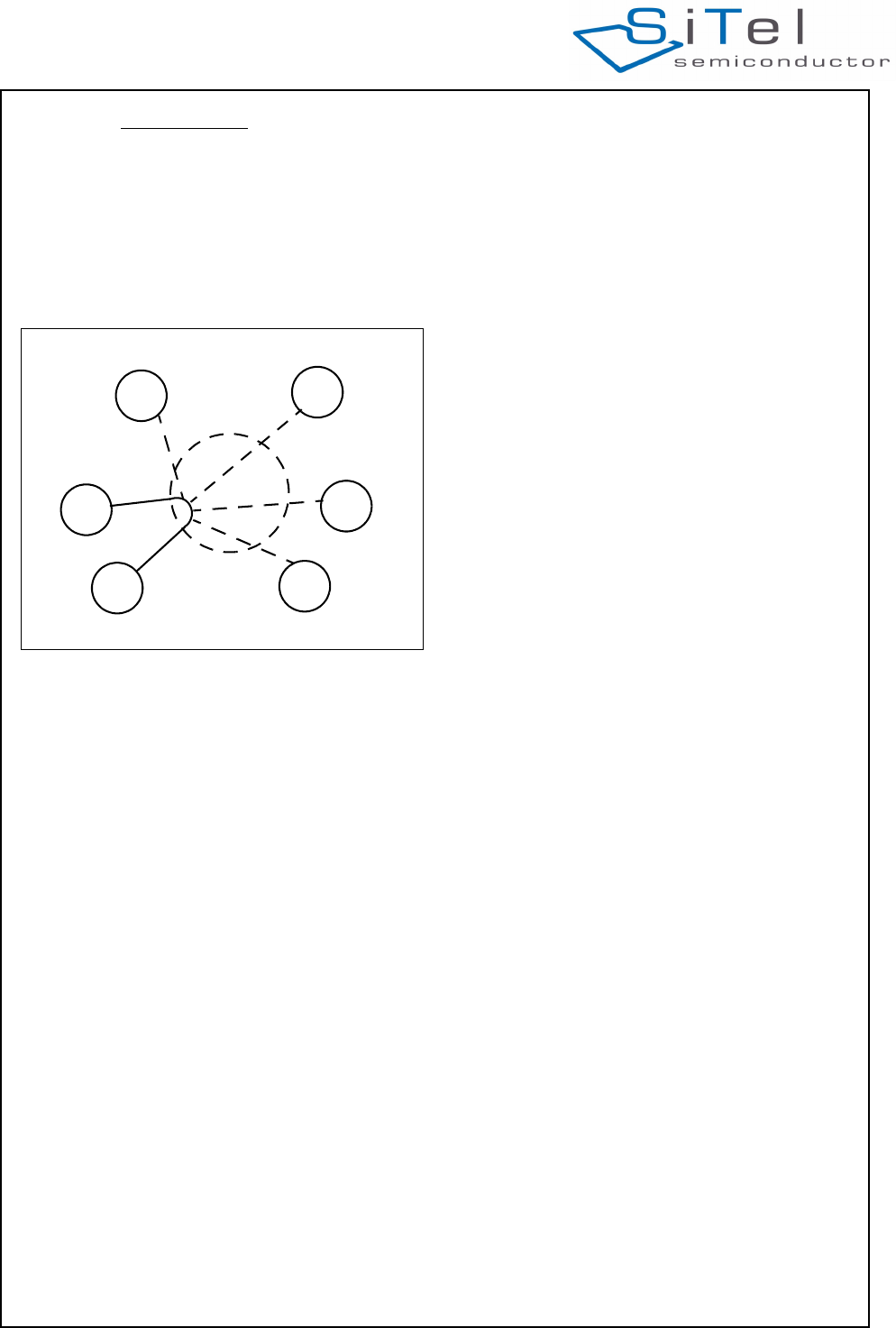
© 2011 SiTel Semiconductor B.V. Company Confidential 23 August 19, 2011 v1.2.1
The following data connections are supported:
• PP to PP (point to point)
• FP to PP, PP to FP
• PP to all PPs (broadcast)
• FP to all PPs (broadcast)
All communication is routed via the FP. The FP has
number #6. See Figure 14.
4.7.5 Broadcasting messages
The broadcast message is 19 bytes at a time and can
real-time clock from the FP to the PP when the real-
time clock is activated.
When broadcasting data no active connections are
established.
The data is transmitted from the FP and received by
any registered PP. The communication is only one
way. Therefore, the broadcast data is not secured
because there is no retransmission.
If the PP does not receive it right the first time, the
broadcast data is lost.
4.7.6 IWU to IWU messaging
The protocol in the SC14CVMDECT module is made
according to the DECT/GAP standard as defined in
EN 300 175 and EN 300 444.
The DECT standard defines an EMC code (see
EN 300 175-5, chapter 7.7.23.). This code is unique for
a DECT product and must be programmed by the
DECT manufacturer to the correct manufacturer code.
The EMC code must be the same for SC14CVMDECT
based product families when using the IWU to IWU
messaging.
If the SiTel default EMC EEPROM value is changed
the IWU to IWU messaging may not operate correctly.
IWU data is transferred in a FA format frame; see
chapter 6.1 in EN 300 175-4. This frame has an
information field of maximum 63 bytes of which
maximum 52 bytes can be used for IWU data. With the
SC14CVMDECT it is only possible to send 5 frames in
a row without pause. The following frame must be an
acknowledge-frame to secure that the internal buffers
within the SC14CVMDECT are emptied.
The FA frame is segmented in 5 bytes fragments and
transferred over the air-interface in the A-field. The 2-
bytes CRC is used to determine if the data is received
correct. If the data is not received correct this is
signalled back to the transmitter by the Q2 bit, and the
data is retransmitted.
The FA frame has a 2 bytes checksum, used to
determine if the complete packet is received correct. If
A checksum error is signalled back to the transmitter
and the complete packet is retransmitted. The packet
will re-transmit until it is received correctly, or the link is
closed.
More transmitted packets will be received in the same
order as they were transmitted. The application must
handle flow control, if needed.
4.8 REGISTRATION
The PP and the FP must be paired using a procedure
called Registration. Without Registration, the PP will be
out-of-lock and will not be able to establish a link to a
FP and therefore not be able to make a call. The
registration uses the unique product identities and
secures the PP and FP to allow no cross-
communication. To avoid cross-communication it is
very important that all the PPs and the FP use an
unique numbering scheme.
The PP can be deregistered from a FP either via the
FP or PP MMI Software using the command interface.
It is also possible to deregister a PP from another
registered PP.
It is possible to pair a PP and FP during the production.
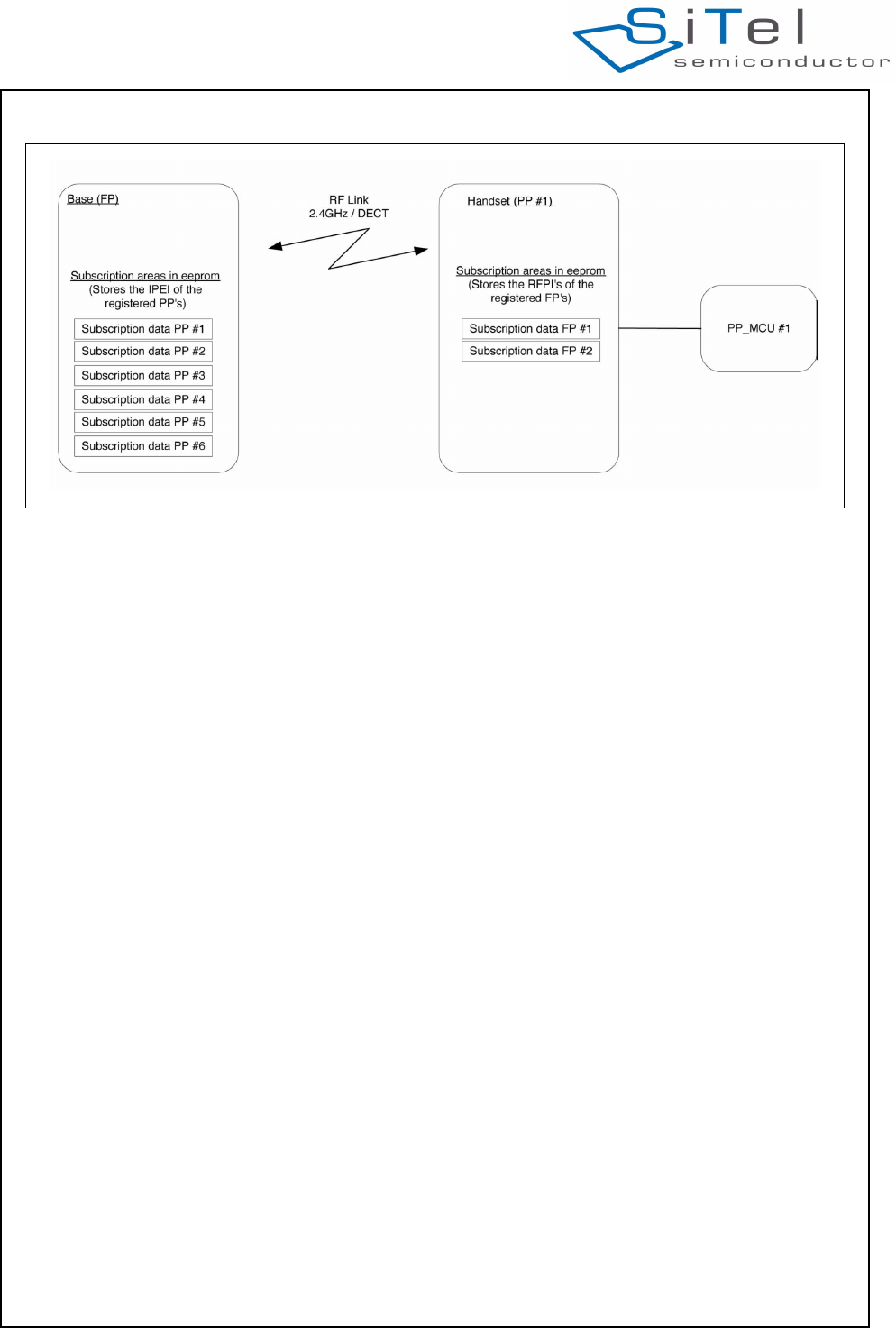
4.8.1 Handling product identities
To secure that the FP and PPs do not make cross-
communications a unique ID must be entered into the
EEPROM of an FP or PP. For the DECT version the ID
for the FP is named RFPI and for the PP the ID is
named IPEI. These numbers are factory settings.
After a successful registration, the IPEI is stored in the
FP and the RFPI is stored in the PP. In this way the two
parts are known to each other and are allowed to make
connections. The registration data are automatically
stored in EEPROM of the FP and PP while making the
registration.
It is possible to register the same PP to 2 FPs, but it
can only be used in one FP at the same time.
Figure 14 Data connection PP0 to PP1 or all
FP
#6
PP
#3
PP
#4
PP
#5
PP
#0
PP
#1
PP
#2
SC14CVMDECT Cordless Voice Module
© 2011 SiTel Semiconductor B.V. Company Confidential 24 August 19, 2011 v1.2.1
4.8.2 Deregistration
There are two ways of deregistering a PP from an FP:
• Remote FP and PP deregistration
The correct way to deregister a PP from an FP is to
deregister it remotely in the FP. If this is done over a
service connection from the PP to the FP, the FP
actually performs the deregistration and then it is
automatically signalled to the PP which in turn will
drop out- of-lock. Using this method it is also
possible to deregister other PPs registered to the FP
from one PP.
Removing all registration at once from the FP (e.g. in
case the original PPs are lost).
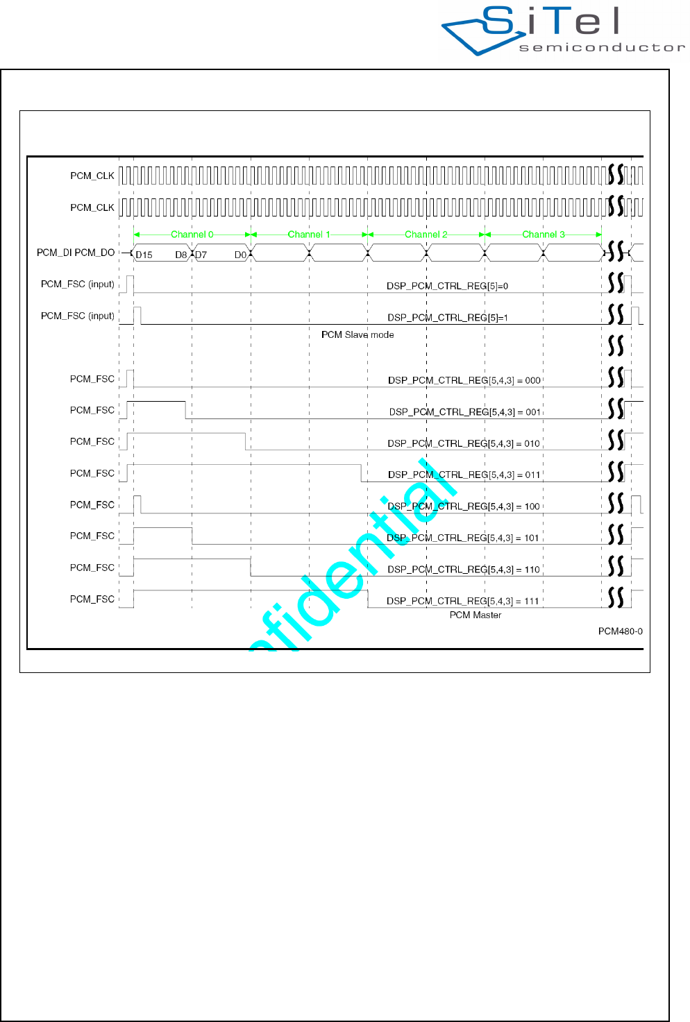
4.9 PCM INTERFACE
The audio is routed between the MCU and the CVM via
the PCM bus. The MCU is responsible for selection
and enabling of the audio path between the PCM bus
and the CVM when calls to the external line are
established. This is done with AT commands.
The CVM is responsible for connecting the right PCM
channel to the right handset for external calls when the
audio path between the CVM and the handset is
opened.
The physical PCM interface formats are illustrated in
the figures in this section.
The CVM supports the following PCM data formats
Linear PCM, 8 kHz sample rate.Used for narrowband
calls (G.726).
Linear PCM, 16 kHz sample rate.Used for wideband
calls (G.722).
G.711 – A-law, 8 kHz sample rate.Used for
narrowband calls (G.726).
G.711 – u-law, 8 kHz sample rate.Used for narrowband
calls (G.726).
• Compressed wideband using A-law, 16 kHz sample
rate.
The 16 bit PCM data is encoded as two 8 bit audio
samples if 8 kHz frame sync is used. Used for
wideband calls (G.722).
• Compressed wideband using u-law, 16 kHz sample
rate.
The 16 bit PCM data is encoded as two 8 bit audio
samples if 8 kHz frame sync is used. Used for
wideband calls (G.722).
Synchronization modes
In slave mode the PCM interface can be configured for
the following synchronization modes:
• Asynchronous system clock: In this mode the clock
of the module is not synchronized to the PCM clock.
This means that audio samples will be either
discarded in case the master PCM clock is faster
than the clock of the module or samples will be
repeated in case the master PCM clock is slower.
• Synchronous system clock: In this mode the clock of
the module will be adjusted to follow the PCM clock
provided by the master. In this case all audio
samples will be kept if the provided PCM clock has
an accuracy of +/- 5ppm which is a DECT radio
requirement.
Figure 15 Handling Product Identities
SC14CVMDECT Cordless Voice Module
© 2011 SiTel Semiconductor B.V. Company Confidential 25 August 19, 2011 v1.2.1
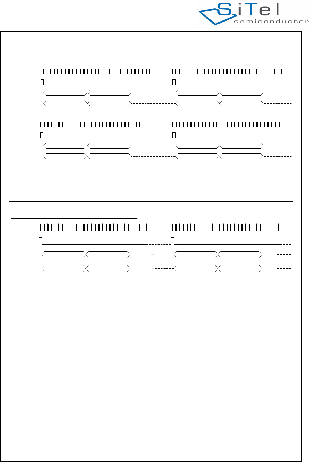
The MCU must make sure that the PCM data format
matches the CODEC selected for the call. Modifying
the CODEC requires the PCM data format to be
changed too. The following figures illustrate the PCM
bus with different PCM data formats (PCM CODEC’s).
Figure 16 PCM Interface Formats
SC14CVMDECT Cordless Voice Module
© 2011 SiTel Semiconductor B.V. Company Confidential 26 August 19, 2011 v1.2.1
Figure 17 PCM bus with linear PCM, 8kHz sample rate
PCM CLK
8 KHz FSC
PCM in
PCM out
Channel 0
Channel 0
Channel 1
Channel 1
Channel 0
Channel 0
Channel 1
Channel 1
AP_DATA_FORMAT_LINEAR_8kHz with 8 kHz frame sync:
1st fram e 2nd fram e1st
fram e
1st fram e 1st
fram e
2nd fram e
2nd fram e 2nd fram e
PCM CLK
16 KHz FSC
PCM in
PCM out
Channel 0
Channel 0
Channel 1
Channel 1 Channel 0 Channel 1
1st fram e 1st fram e
1st fram e 1st fram e
AP_DATA_FORMAT_LINEAR_8kHz with 16 kHz frame sync:
1st fram e 1st fram e
Channel 0 Channel 1
1st fram e 1st fram e
Figure 18 PCM bus with linear PCM, 16kHz sample rate
PCM CLK
16 KHz FSC
PCM in
PCM out
Channel 0
Channel 0
Channel 1
Channel 1
Channel 0
Channel 0
Channel 1
Channel 1
1st frame 2nd frame1st frame
1st frame 1st frame
2nd frame
2nd frame 2nd frame
AP_DATA_FORMAT_LINEAR_16kHz with 16 kHz frame sync:
SC14CVMDECT Cordless Voice Module
© 2011 SiTel Semiconductor B.V. Company Confidential 27 August 19, 2011 v1.2.1
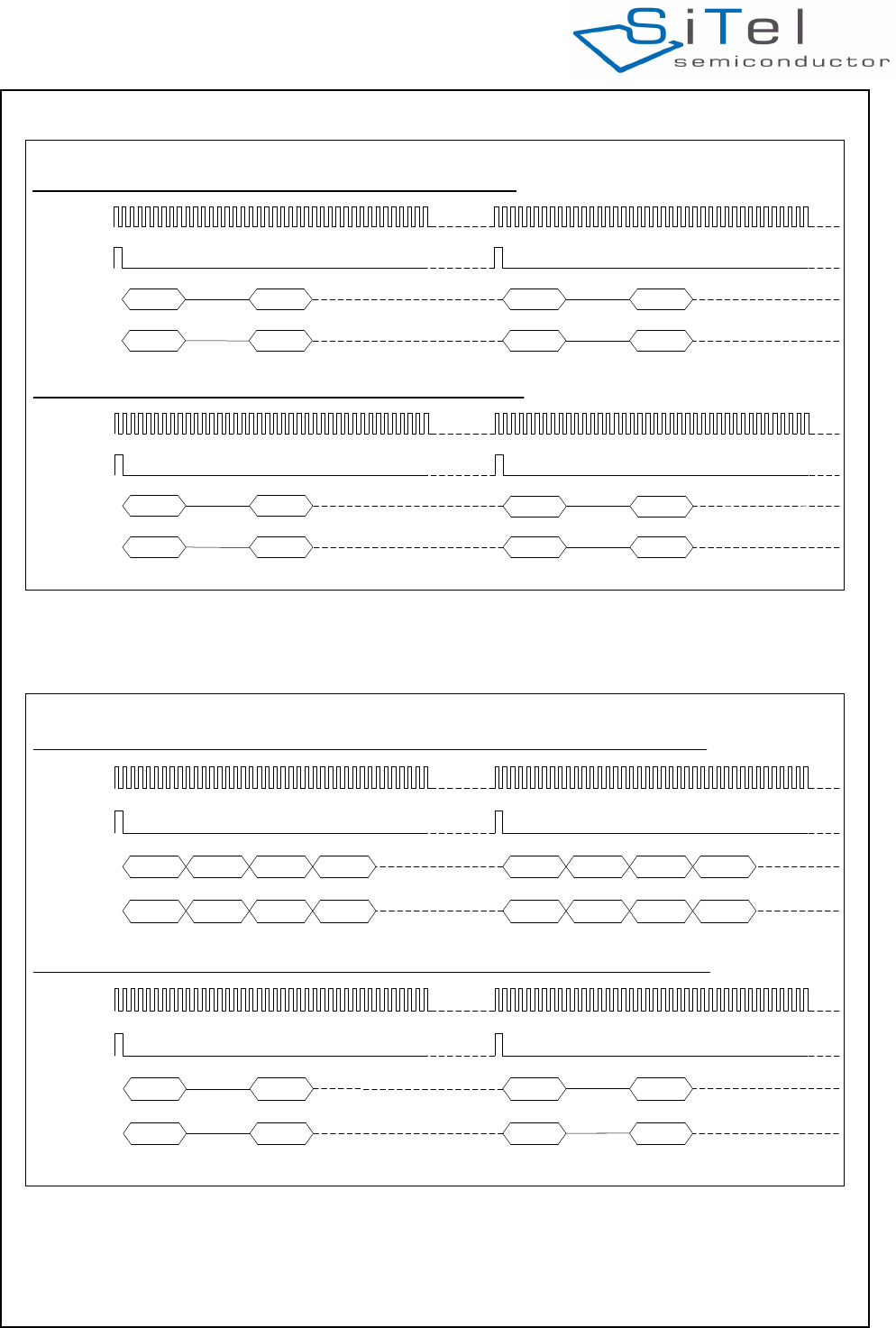
Figure 19 PCM bus with G.711 – A-law/u-law, 8 kHz sample rate
PCM CLK
8 KHz FSC
PCM in
PCM out
Channel 0
Channel 0
Channel 1
Channel 1
Channel 0
Channel 0
Channel 1
Channel 1
AP_DATA_FORMAT_G711A / AP_DATA_FORMAT_G711U with 8 kHz frame sync:
1st frame
1st frame
2nd frame
2nd frame
1st frame
1st frame
2nd frame
2nd frame
PCM CLK
16 KHz FSC
PCM in
PCM out
Channel 0
Channel 0
Channel 1
Channel 1 Channel 0 Channel 1
AP_DATA_FORMAT_G711A / AP_DATA_FORMAT_G711U with 16 kHz frame sync:
1st frame
1st frame
1st frame
1st frame 1st frame 1st frame
Channel 0 Channel 1
1st frame 1st frame
Figure 20 PCM bus with compressed wideband using A-law/ u-law, G722 used on air interface.
PCM CLK
16 KHz FSC
PCM in
PCM out
Channel 0
Channel 0
Channel 1
Channel 1
Channel 0
Channel 0
Channel 1
Channel 1
AP_DATA_FORMAT_CWB_ALAW / AP_DATA_FORMAT_CWB_ULAW with 16 kHz frame sync (G.722 used on air):
1st frame
1st frame
1st frame
1st frame
2nd frame
2nd frame
2nd frame
2nd frame
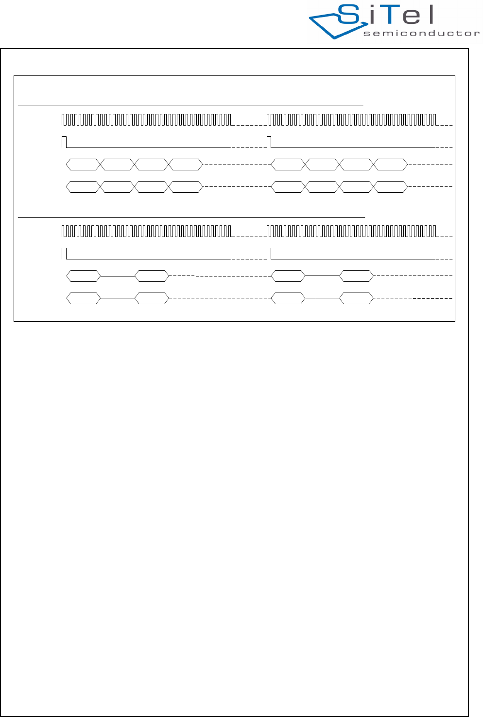
PCM CLK
8 KHz FSC
PCM in
PCM out
Channel 0
Channel 0
Channel 1
Channel 1
Channel 0
Channel 0
Channel 1
Channel 1
Channel 0
Channel 0
Channel 1
Channel 1
Channel 0
Channel 0
Channel 1
Channel 1
AP_DATA_FORMAT_CWB_ALAW / AP_DATA_FORMAT_CWB_ULAW with 8 kHz frame sync (G.722 used on air):
1st frame
1st frame
2nd frame
2nd frame
1st frame
1st frame
2nd frame
2nd frame
3rd frame4th frame 3rd frame4th frame
4th frame 3rd frame4th frame3rd frame
SC14CVMDECT Cordless Voice Module
© 2011 SiTel Semiconductor B.V. Company Confidential 28 August 19, 2011 v1.2.1
Figure 21 PCM bus with compressed wideband using A-law/ ?-law, G726 used on air interface.
PCM CLK
16 KHz FSC
PCM in
PCM out
Channel 0
Channel 0
Channel 1
Channel 1
Channel 0
Channel 0
Channel 1
Channel 1
AP_DATA_FORMAT_CWB_ALAW / AP_DATA_FORMAT_CWB_ULAW with 16 kHz frame sync (G.726 on air):
1st frame
1st frame
1st frame
1st frame
PCM CLK
8 KHz FSC
PCM in
PCM out
Channel 0
Channel 0
Channel 1
Channel 1
Channel 0
Channel 0
Channel 1
Channel 1
Channel 0
Channel 0
Channel 1
Channel 1
Channel 0
Channel 0
Channel 1
Channel 1
AP_DATA_FORMAT_CWB_ALAW / AP_DATA_FORMAT_CWB_ULAW with 8 kHz frame sync (G.726 on air):
1st frame
1st frame
2nd frame
2nd frame
1st frame
1st frame
2nd frame
2nd frame
2nd frame
2nd frame
2nd frame
2nd frame
1st frame
1st frame
1st frame
1st frame
1st frame
1st frame
1st frame
1st frame

SC14CVMDECT Cordless Voice Module
© 2011 SiTel Semiconductor B.V. Company Confidential 29 August 19, 2011 v1.2.1
5.0 CAT-iq
5.1 INTRODUCTION
CAT-iq stands for Cordless Advanced Technology,
Internet and Quality. It is the new global technology
initiative from the DECT Forum, designed for IP-voice
services in the next generation networks. CAT-iq is
based on the regulatory framework of the mature and
reliable
DECT technology. It is fully backward compatible to
DECT GAP and, as the new cordless phone standard,
focuses on high quality Audio VoIP (wideband) as
well as low bit-rate data applications as the next
generation Cordless Phone standard.
5.2 CAT-IQ PROFILE OVERVIEW
The CAT-iq profiles are split between voice and data
services, with CAT-iq 1.0 and CAT-iq 2.0 providing
features to support key voice enhancements, and CAT-
iq 3.0 and CAT-iq 4.0 providing features to support
data. Each profile has a corresponding ETSI
specification, the organization where the technical
experts have realized the requirements as defined for
each profile by the DECT Forum.
5.2.1 CAT-iq 1.0
• Narrowband (G.726) and wideband (G.722) audio
and switching between these two codecs is
supported.
• CLIP, CNIP, CLIR: Calling Line Identification
Presentation, Calling Name Identification, Calling
Line Identity Restriction for internal and external
calls.
5.2.2 CAT-iq 2.0 (Supported in future releases)
• Synchronization of call lists and telephone books,
missed calls list, incoming accepted calls list,
internal names list (unique identifier of each
handset), base telephone book
• Synchronization of system settings: PPs are enabled
to change partly the configuration of the system
consisting of FP and PPs, these system settings are
handled using the list access method. Using this
method, the FP and the PPs support:
• Synchronization of time and date for FP and PPs,
that FP is enabled to transmit time and date to the
PPs.
• Reset to factory settings, means that PP is ena-
bled to reset the FP configuration to it’s factory
setting.
• Obtaining FP versions, means that a PP can
obtain the software release of the FP.
• Multiple lines handling: The behavior of DECT
systems connected to more than one network lines.
These lines may be of different types (VoIP and
PSTN for example). This feature details how calls
are placed in a multiple lines context. This feature
also impacts the behaviour of other services in order
to ensure attachment of PPs to a line, line settings
and several lists properly.
• Parallel calls: initiating a second call in parallel to the
first call, toggling between calls, putting a call on
hold, resuming calls from on hold, call transfer, 3-
party conference with established external and/or
internal calls
• DTMF and tones
• Headset support
• Easy PIN code registration
• Easy pairing
• handset location
SC14CVMDECT Cordless Voice Module
© 2011 SiTel Semiconductor B.V. Company Confidential 30 August 19, 2011 v1.2.1
6.0 Specifications
6.1 ABSOLUTE MAXIMUM RATINGS
Note 1: Absolute maximum ratings are those values that may be applied for maximum 50 hours.
Beyond these values, damage to the device may occur.
Table 7: Absolute Maximum Ratings (Note 1)
Description Condition Min Max Unit
Maximum supply voltages:
VBAT 5.5 V
VBATT, VCCRF, VDDPA 3.6 V
VDDIO 2 V
Maximum voltage on pins:
PON 5.5 V
Port pins 2 V
LED4, LED3 3.6 V
ESD voltage
all pins human body model 2000 V
machine model 100 V
Table 8: Operating Conditions
Description Condition Min TYP Max Unit
Supply voltage:
VBAT 2.1 5.5 V
VBATT, VCCRF, VDDPA 2.1 3.45 V
VDD The module provides an
output voltage in this range
1.8 V
VDDIO 1.65 1.65 1.98 V
Voltage on pins:
PON pin 2.1 5.5 V
P2[0]/LED4, P2[1]/LED3 3.45 V
All other pins 2 V
Maximum Currents through pins
CHARGE pin Series resistor
R>(Vcharger-3)/10mA
10 mA
CLASSD pins 500 mA
VREFp 1mA
SC14CVMDECT Cordless Voice Module
© 2011 SiTel Semiconductor B.V. Company Confidential 31 August 19, 2011 v1.2.1
6.2 DIGITAL INPUT LEVELS
6.3 DIGITAL OUTPUT LEVELS
6.4 LOUDSPEAKER LOAD CIRCUITS
Table 9: DIGITAL INPUT LEVELS
Description Condition Min Max Units
Logic 0 input level
all digital pads, except PON, CHARGE VDD=1.8V 0.3 x VDD V
PON 0.9 V
CHARGE 0.9 V
RSTn 0.2 x VDD V
Logic 1 input level
all digital pads, except PON, CHARGE VDD = 1.8 V 0.7 x VDD V
PON 1.5 V
CHARGE 1.5 V
RSTn 0.8xVDD V
Table 10: Digital Output Levels
Descriptions Conditions Min Max Units
Logic 0 output level
(For drive capability see pin description)
Iout = 2,4,8 mA
VDD = 1.8 V
0.2 x VDD V
Logic 1 output level Iout = 2,4,8 mA
VDD = 1.8 V
0.8 x VDD V
Table 11: LSRp/LSRn load circuits
PARAMETER DESCRIPTION CONDITIONS MIN TYP MAX UNITS
Cp1_Rl1_inf Load capacitance see Figure 22, RL1 = 30 pF
Cp1_Rl1_1k Load capacitance see Figure 22, RL1 k100 pF
Rl1 Load resistance 28
Cp2 Parallel load
capacitance
see Figure 23 30 pF
Cs2 Serial load capacitance 30 F
Rl2 Load resistance 600
Figure 22 Load circuit A Dynamic loudspeaker
RL1 Cp1
LSRp
LSRn
Figure 23 Load circuit B Piezo loudspeaker
Cs2
LSRp
LSRn
RL2
Cp2
SC14CVMDECT Cordless Voice Module
© 2011 SiTel Semiconductor B.V. Company Confidential 32 August 19, 2011 v1.2.1
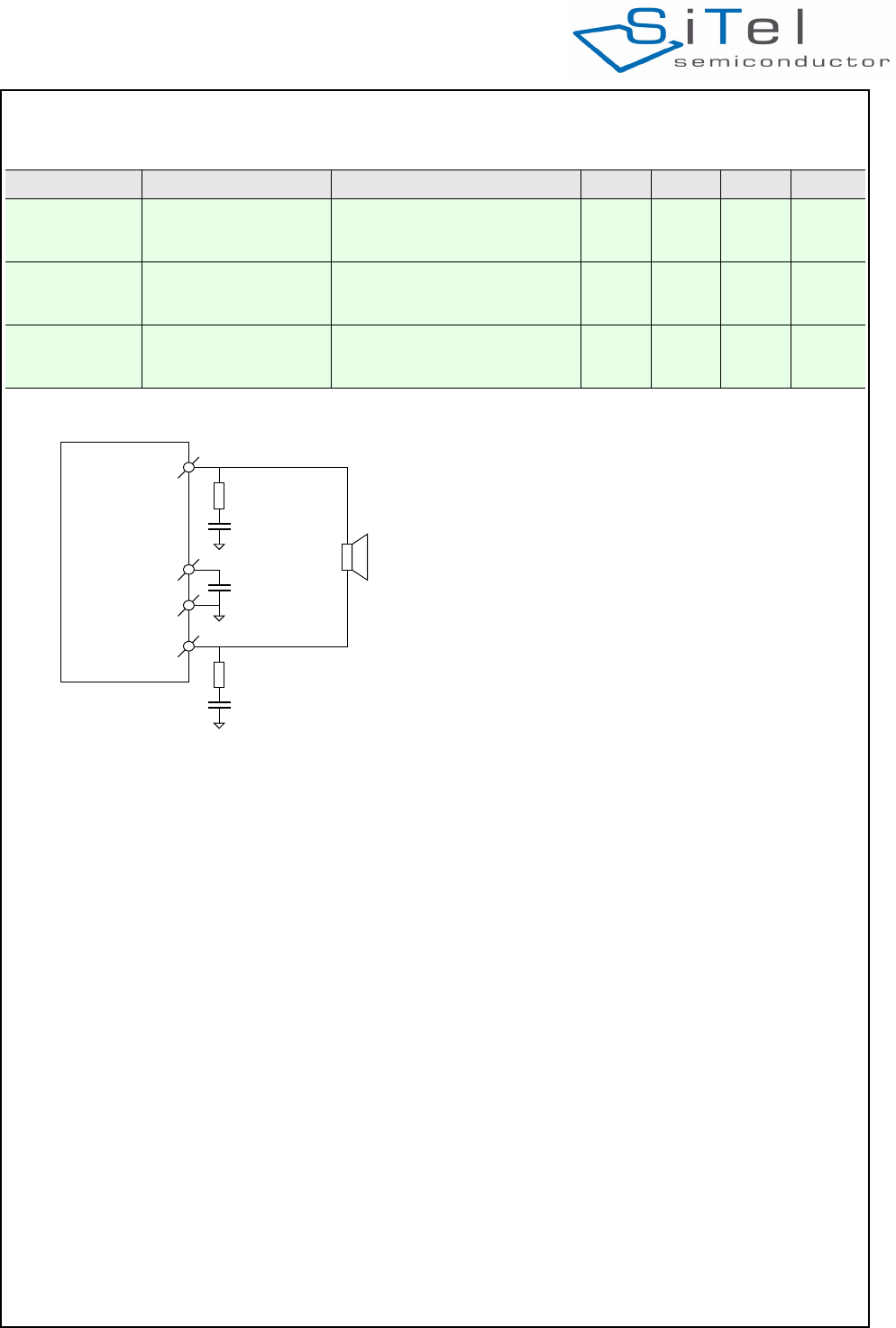
Table 12: PAOUTp, PAOUTn external components
PARAMETER DESCRIPTION CONDITIONS MIN TYP MAX UNITS
C_VDDPA Decoupling capacitor on
VDDPA
Required when Class-D is used
and guaranteed life time.
(see Figure 24)
1F
Cs_PAOUT Snubber capacitor (to
reduce ringing at
PAOUTp/n)
Required when Class-D is used
to prevent EMI and guaranteed
life time. (see Figure 24)
1nF
Rs_PAOUT Snubber resistor (to
reduce ringing at
PAOUTp/n)
Required when Class-D is used
to prevent EMI and guaranteed
life time. (see Figure 24)
1
Figure 24 Class-D external components
PAOUTp
PAOUTn
VDDPA
VSS/GND
May 10, 2010
C_VDDPA
Cs_PAOUT
Rs_PAOUT
Cs_PAOUT
Rs_PAOUT
SC14CVMDECT Cordless Voice Module
© 2011 SiTel Semiconductor B.V. Company Confidential 33 August 19, 2011 v1.2.1
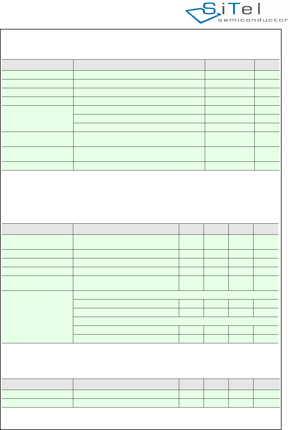
6.5 GENERAL SPECIFICATIONS
Note 2: The resulting range is very dependent of the mechanical design. SiTel is not responsible for this design and as such SiTel is not responsible
for the resulting range performance of the final product.
6.6 BASEBAND SPECIFICATIONS
6.7 RADIO PART (RF) SPECIFICATIONS
Table 13: SC14CVMDECT module
Item Condition Value Unit
Dimension l x w x h 25.0 x 29.0 x 2.9 mm
Weight 4.5 g
Temperature Range -20 to +60 °C
Frequency range According to DECT standard 1870 to 1930 MHz
Antenna Range According to DECT standard; (Note 2)
- typical outdoor 350 m
- typical indoor 75 m
Standard Compliancy ETS 300 444 (DECT GAP), former TBR2214
FCC part 15
Power supply 2 or 3 cell NiCd/NiMH
Note for 1 Li-Ion battery an external LDO is required.
2.10 to 3.45V V
Maximum PCB warpage For entire reflow range 0.1 mm
Table 14: Baseband specifications
Item Specification Min Typ Max Unit
Serial Interface baud rate UART; Interface for external
microprocessor or PC
115.2 kBits
Flash Download baud rate Via UART 115.2 kBits
Flash data space Module Flash 4kByte
EEPROM data space Module EEPROM 0.4 kByte
Analog front-end/Audio PP/FP Application: Interface for
Microphone, Earpiece, Headset
Power consumption
(charge)
FP Application (3.3V):
- stand by mode 55 60 mA
- talk mode 65 70 mA
PP Application (3.3V):
- stand by mode 4,5 6mA
- talk mode 30 40 mA
Table 15: Radio part (RF)
Item Conditions Min Typ Max Unit
Receive sensitivity @ BER = 0.001 -93 -92 -89 dBm
Receive IIP3 -20 dBm
SC14CVMDECT Cordless Voice Module
© 2011 SiTel Semiconductor B.V. Company Confidential 34 August 19, 2011 v1.2.1
6.8 FP POWER SUPPLY
Transmit Power (NTP) DECT: 200 mW 20 23 25.5 dBm
DECT6.0: 115 mW (max peak) 18.5 21 24 dBm
TDMA (time division
multiple access)
6xRx + 6xTx time slots per carrier
Data rate 1.152 Mbits/s
Modulation depth DECT GFSK bandwidth = 20 dB < 1,728 MHz
Antenna diversity Two built-in antenna’s
Standard Compliancy ETS 301 406 (former TBR6)
Table 15: Radio part (RF)
Item Conditions Min Typ Max Unit
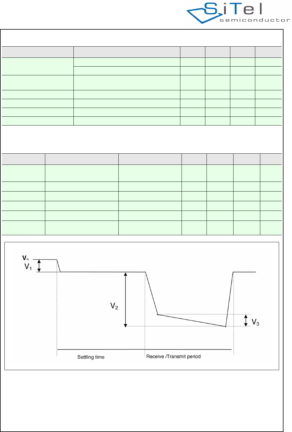
Table 16: Requirements for linear supply regulator
Parameter Description Condition Min Typ Max Unit
VCCRF Voltage at VCCRF Unloaded VB
Loaded VB-V1-V2-V3
2.1 3V 3.45 V
V1Settling time I = 50 mA 20 mV
V2Receive period I = 130 mA 100 mV
V2Transmit period I = 400 mA 200 mV
V3Drop during transmit 25 mV
Additional ripple (DC/DC) none none none mV
Figure 25 FP power supply
B

SC14CVMDECT Cordless Voice Module
© 2011 SiTel Semiconductor B.V. Company Confidential 35 August 19, 2011 v1.2.1
7.0 Design guidelines
This section describes the software and hardware
considerations taken into account when designing the
target application.
The SC14CVMDECT can be used standalone or next
to an MCU that controls the module. In case the
module is used standalone the application will be
stored in its on-board Flash. In total 324kBytes of Flash
are available for this.
Applications can be written with the Athena software
development environment (see [4]).
7.1 APPLICATION SOFTWARE FOR PP
In a PP application the following software tasks must
be handled by the MCU or within the module itself:
• UART communication (external microprocessor
only)
• PP MMI
• Display interface (optional)
• Keyboard interface (optional)
• Battery Charge interface (optional)
• Audio handling
• Tone / Melodies handling
For control commands see document reference [1].
UART communication
The UART communication is the main control interface
of the SC14CVMDECT.
PP MMI
The MMI state machine must handle the call setup and
call termination on the PP.
Display Interface
The MCU / PP handles the display interface including
the display driver.
Keyboard Interface
The MCU/ PP handles the keyboard interface including
the keyboard driver.
Battery Charge handling
SC14CVMDECT V3 supports no battery management.
This must be done by and external charge circuit on
combination with the external MCU. The Application
Software must handle the MMI part such as battery
status for the user and the PP battery current
consumption states.
Audio handling
The Application Software state machine must control
when to open and close the audio. The headset plug-in
detection must handled by the host, and a status is
send to the PP MMI from the PP. The PP MMI must
handle the volume control.
Headset detection boundaries can be adjusted in
EEPROM. When headset indication is received from
the PP Headset detection logic (future release), the
Application Software can decide if audio should be
switched to the headset and sends a request to the
SC14CVMDECT.
The PP audio handling basically consists of 4 audio
states (see Figure 9):
1. Idle (Alert) State
2. Earpiece State
3. Handsfree State (Speakerphone)
4. Headset State
Shifting between states is done through the API.
Please refer to the PP application layout for pin
connections.
Tone handling
The Application Software state machine must control
when to play tones and the volume setting. Custom
melodies can be defined in the EEPROM.
7.2 APPLICATION SOFTWARE FOR FP
In an FP application the following software tasks must
be handled by the MCU or within the module itself:
• UART communication (external microprocessor
only)
•FP MMI
• Display interface (optional)
• Keyboard interface (optional)
• Audio handling
• Tone / Melodies handling
For control commands see document reference [1].
UART Communication
The UART communication forms the basic of the FP
operation because via this interface the
SC14CVMDECT is controlled.
PP MMI
The MMI state machine must handle the call setup and
call termination on the FP.
Display Interface
The MCU/ FP handles the display interface including
the display driver.
Keyboard Interface
The MCU/ FP handles the keyboard interface including
the keyboard driver.
Audio Handling
The Application Software state machine must control
when to open and close the audio. The headset plug-in
detection is handled by the FP, and a status is send to
the FP MMI from the FP. The FP MMI must handle the

SC14CVMDECT Cordless Voice Module
© 2011 SiTel Semiconductor B.V. Company Confidential 36 August 19, 2011 v1.2.1
volume control.
Headset detection boundaries can be adjusted in
EEPROM. When headset indication is received from
the FP headset detection logic (future release), the
Application Software can decide if audio should be
switched to headset and sends a request to the FP.
Tone Handling
The Application Software state machine must control
when to play tones and the volume setting. Custom
melodies can be defined in EEPROM.
7.3 HARDWARE DESIGN GUIDELINES
Within this section general design guidelines for
SC14CVMDECT FP and PP applications are given.
7.3.1 Circuit design Guidelines
For a reference schematic refer to the SC14CVMDECT
reference kit. With the reference kit package a non-
cost optimized reference design is presented.
For a FP hardware design the following hardware parts
will be needed besides the SC14CVMDECT:
• Supply voltage
• Battery charge
• LED and buttons
• Speakerphone
For a PP hardware design the following hardware parts
will be needed besides the SC14CVMDECT:
• Power
• Battery Charger
• Audio:
• Microphone
• Earpiece
• Speaker
• Headset
7.3.2 PCB Design Guidelines
• Because of the presence of the digital radio
frequency burst with 100 Hz time division periods
(TDD noise), supply ripple and RF radiation, special
attention is needed for the power supply and ground
PCB layout.
• Power supply considerations
Both high and low frequency bypassing of the supply
line connections should be provided and placed as
close as possible to the SC14CVMDECT. In order to
get the best overall performance for both FP and PP
applications, a number of considerations for the PCB
has to be taken into account.
• The width of the power amplifier supply line is rec-
ommended to be between 0.8 and 1.2 mm due to
high current peaks during RF bursts.
• Make angle breaks on long supply lines to avoid
resonance frequencies in respect to DECT fre-
quencies. Maximum 8 cm before an angle break
is recommended.
• Supply lines should be placed as far as possible
away from sensitive audio circuits. If it is neces-
sary to cross supply lines and audio lines, it
should be done with right angles between supply
and audio lines/circuits (microphone, ear-speaker,
speakerphone, etc.)
• Ground plane considerations
In order to achieve the best audio performance
and to avoid the influence of power supply noise,
RF radiation, TDD noise and other noise sources,
it is important that the audio circuits on both FP
and PP applications boards are connected to the
GND_ANA pins (analog ground) on the
SC14CVMDECT with separate nets in the layout.
It is advised to provide the following audio circuits
with separate ground nets connected to the
GND_ANA pins:
• Microphone(s)
• Headset microphone and speaker
• Speakerphone (signal grounds)
Depending on the layout it may also be necessary to
bypass a number of the audio signals listed above to
avoid humming, noise from RF radiation and TDD
noise with. It is also important to choose a microphone
of appropriate quality with a high RF immunity (with
built-in capacitor).
• ESD performance
Besides TDD noise, the ESD performance is
important for the end-application. In order to achieve
a high ESD performance supply lines should be
placed with a large distance from charging terminals,
display, headset connector and other electrical
terminals with direct contact to the ESD source.
On a two-layer PCB application it is important to
keep a simulated one layer ground. With a stable
ground ESD and TDD noise performance will always
improve.

SC14CVMDECT Cordless Voice Module
© 2011 SiTel Semiconductor B.V. Company Confidential 37 August 19, 2011 v1.2.1
8.0 Audio Level Adjustment
8.1 PP AUDIO LEVEL
For adjusting the audio levels in the PP (SLR/TOLR)
and (RLR/OLR) the related eeprom parameters can
be adjusted during production.
8.2 FP AUDIO LEVEL)
For adjusting the audio level in the FP (SLR/TOLR)
and (RLR/ROLR) he related eeprom parameters can
be adjusted during production.
.
SC14CVMDECT Cordless Voice Module
© 2011 SiTel Semiconductor B.V. Company Confidential 38 August 19, 2011 v1.2.1
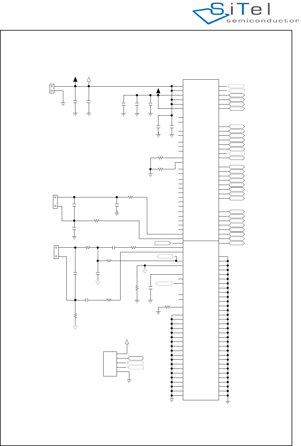
9.0 Example Application Diagram
Figure 26 Referencediagram
%DWWHU\
&RQQHFWRU
0LFURSKRQH
(DUSLHFH
$ 9%$7
% 9%$77
' 9''
( 9''3$
& 9&&5)
$ 9'',2
) 62&3
( 62&1
( &+$5*(B&75/
+ 21(B&(//
) 8/3B0$,1
) 8/3B9%$7
) 8/3B3257
+ 1&
* '&B&75/
) '&B&75/1
+ 1&
/ 5)
/ 5)3
) 5)321
- 5)3
% &3B9287
$ &3B9287
. :/('
. :/('
/ :/('
+ /653
* /651
. 5)
.
5,1*1
-
5,1*2875,1*,1*
.
3$5$'(7
*
$'&
.
3>@&,',13
'
'33$2873
&
'33$2871
&
,17%;7$/
%
,17:7)B,1
'
6)3&0B)6&
'
'36&/3&0B'2
)
'36'$3&0B',
+
&/.3&0B&/.
-
(&=3:0/('
.
(&=3:0/('
'
&+$5*(
'
321
%
,179''(5',
&
,177'2'
)
,17,176,2
$
,17,176.
&
,17,17/(
)
,17$'&
(
3:063,B',
)
63,B'2
%
63,B&/.
$
63,B(1
. 5)
+ 5)3
%
3:085;
&
87;
- 0,&+
. 0,&3
/ 0,&1
. 95()3
+ 95()0
$ 5671
) $'&
& -7$*
' *1'
0 73
% 73
$ *1'
$ *1'
% *1'
% *1'
% *1'
& *1'
& *1'
& *1'
(
*1'
(
*1'
(
*1'
(
*1'
(
*1'
*
*1'
*
*1'
*
*1'
*
*1'
* 1&
*
*1'
*
*1'
*
*1'
+
*1'
+
*1'
+
*1'
-
*1'
-
*1'
-
*1'
-
*1'
-
*1'
-
*1'
-
*1'
.
*1'
/
*1'
/
*1'
/
*1'
/
*1'
/
*1'
/
*1'
/
*1'
+
5,1*3
& *1'
% *1'
% *1'
$ *1'
$ *1'
$ *1'
(
*1'
(
*1'
' *1'
' *1'
' *1'
' *1'
6&&90'(&7
&
S)
&
S)
&
S)
&
S)
&
X)
9
-
&
X)
9
&
X)
9
5
5
&
X)
9
&
'1$
5
5
&
X)
9
5
5
&
'1$
5
.
-
5
5
5
.
5
5
5
5
&
'1$
&
'1$
&
'1$
-
-
%0%65667%
3URJUDPPLQJ3LQV
&
S)
5
'1$
5
'1$
5
'1$
9%$79%$7
$*1'
$*1'
0,&+
$*1'
3B
87;
321
85;
85;
87;
9''
*1' *1'
*1'
*1'
*1'
*1'*1'
*1'*1'
*1'*1'
*1'
*1'
-7$*
-7$*
3B
3B
3B
3B
3B
3B
3B
3B
3B
3B
3B
3B
3B
3B
3B
3B
3B
3B
3B
3B
3B
3B
3B
3B
3B
3B
*1'
95()3
*1'
*1'
*1'
9''
SC14CVMDECT Cordless Voice Module
© 2011 SiTel Semiconductor B.V. Company Confidential 39 August 19, 2011 v1.2.1
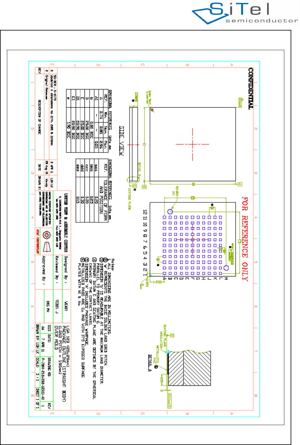
10.0 Mechanical Dimensions
Figure 27 Package Outline Drawing
SC14CVMDECT Cordless Voice Module
© 2011 SiTel Semiconductor B.V. Company Confidential 40 August 19, 2011 v1.2.1
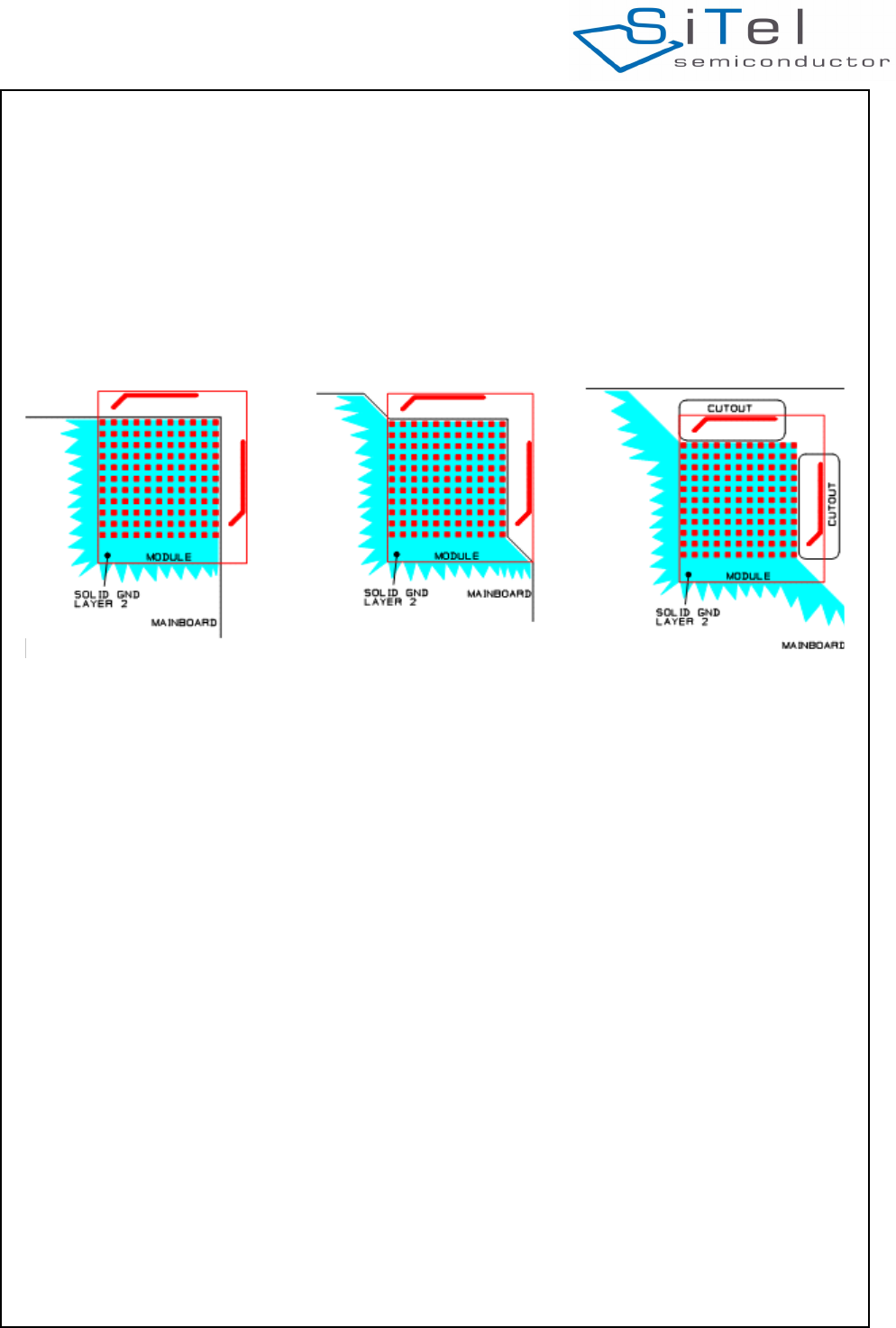
11.0 Module integration
11.1 MODULE PLACEMENT ON THE MAIN BOARD
In order to ensure FCC compliance, proper coverage
and to avoid detuning of the antennas, it required to
place the module free on the main board in relation to
other surrounding materials.
Keep a distance of at least 10 mm from the antenna
elements to conducting objects and at least 5 mm to
non-conducting objects.
Keep in mind that electrical shielding objects, even
partly surrounding the antennas, will normally cause a
significant degradation of the coverage.
Place the module at the corner of the main-board as
shown in Figure 28.
If the module has to be placed away from the edge of
the main-board, then avoid conducting areas in front of
the antennas and make a cut-out in the main board
underneath the antennas as shown in the figure.
Keep solid ground on layer 2 out to the edges of the
main board as shown.
Figure 28 Module placement on the main board (top view)

SC14CVMDECT Cordless Voice Module
© 2011 SiTel Semiconductor B.V. Company Confidential 41 August 19, 2011 v1.2.1
12.0 UTAM membership waiver
Payment of the Up Front Membership Fee and Per
Radiating Device Fees is not required from a
manufacturer or distributor that uses an FCC-certified
module for which such fees have been paid. Such an
“FCC certified module” is defined as a device that
contains the complete UPCS-compliant radio modem
functionality from a supplier that has a valid UTAM
Affidavit. The hardware and firmware implementation
of the FCC certified module must not be modified by
the manufacturer or distributor in a way that would
invalidate its original FCC certification unless the
manufacturer of the device that will contain the module
secures its own FCC approval. Any applicant for FCC
approval seeking to use an FCC certified module must
give the FCC ID number of the certified module that it
will employ and attest that it is using a module for
which UTAM fees have been paid.
See also www.utam.org
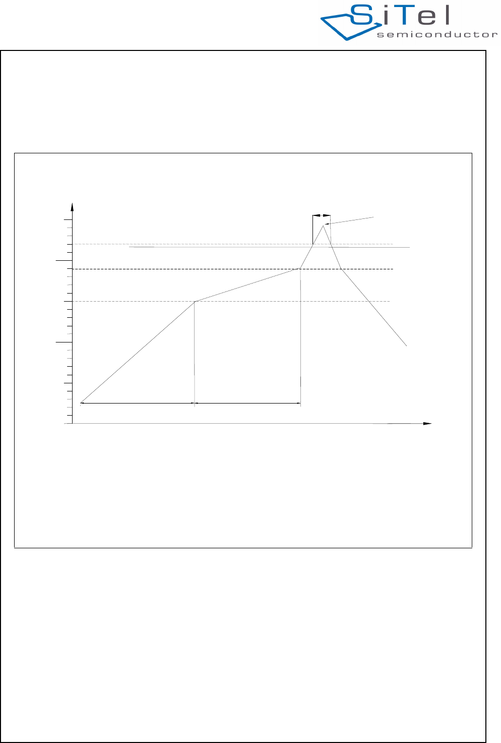
SC14CVMDECT Cordless Voice Module
© 2011 SiTel Semiconductor B.V. Company Confidential 42 August 19, 2011 v1.2.1
13.0 Soldering
13.1 SOLDERING PROFILE
The SC14CVMDECT should be soldered using a
standard reflow soldering profile and lead free solder
paste as shown below. Adjustments to the profile may
be necessary depending on process requirements.
13.2 COPPER PAD AND SOLDER OPENING
Recommended Copper Pad and Solder Mask Opening
(NSMD).
Figure 29 Reflow profile
t1: Max. Change in temperature
3°C/sec.
t2: Time in preheat (150°C < temp.
< 190°C)
60 -
120 sec.
t3: Time in reflow zone (temp. > 220°C) 30 -
60 sec.
t4: Peak temperature
237°C±5°C
T1 Preheat zone botto
m
150°C
T2 Preheat zone top 190°C
T3 Reflow zone 220°C
0°
T1 150°C
T2 190°C
T3 220°C
50°
t1 t2
Meltingpoint 217°C
150°
100°
250°
200°
Reflow profile – leadfree
Sn96.5-Ag3.0-Cu0.5
t3 t4
Temp. C°
Time
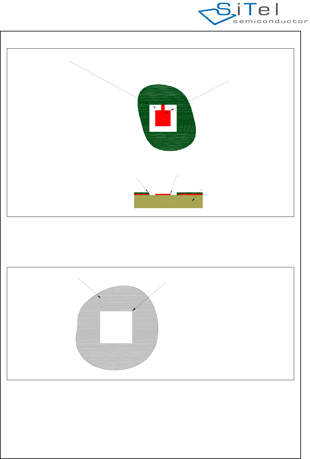
SC14CVMDECT Cordless Voice Module
© 2011 SiTel Semiconductor B.V. Company Confidential 43 August 19, 2011 v1.2.1
13.3 STENCIL
For the stencil a thickness of 0.122 mm is
recommended. Recommended opening is as shown
below.
Figure 30 Copper pad and Solder mask opening
Cu. pad 1.00x1.00mm
Solder mask opening 1.80x1.80mm
Substrate
Copper pads
Solder Mask
1.00x1.00
0.80x0.80
Figure 31 Stencil
Stencil
Opening in stencil 1.40 x 1,40mm
0.80x0.80

SC14CVMDECT Cordless Voice Module
© 2011 SiTel Semiconductor B.V. Company Confidential 44 August 19, 2011 v1.2.1
14.0 Notices to OEM
14.1 FCC REQUIREMENTS REGARDING THE END
PRODUCT AND THE END USER.
This module is for use only in DECT / UPCS handsets
and base stations.
The antenna(s) used for this transmitter must not be
co-located or operating in conjunction with any other
transmitter
The end product that the module is integrated into must
be marked as follows:
"Contains Transmitter Module FCC ID: Y82-SC14A /
IC: 9576A-SC14A"
The literature provided to the end user must include the
following wording:
FCC compliance statement
This device complies with Part 15 of the FCC Rules.
Operation is subject to the following two conditions: (1)
this device may not cause harmful interference, and (2)
this device must accept any interference received,
including interference that may cause undesired
operation of the device.
Module transmetteur ID IC: 9576A-SC14A
Son fonctionnement est soumis aux deux conditions
Suivantes: (1) cet appareil ne doit pas causer
D'interférences nuisibles et (2) appareil doit accepter
Toute interference recue, y compris les interferences
Qui peuvent pertuber le fonctionnement.
Changes or modifications to the equipment not
expressly approved by the Party responsible for
compliance could void the user's authority to Operate
the equipment.
NOTE: This equipment has been tested and found to
comply with the limits for a Class B digital device,
pursuant to Part 15 of the FCC Rules. These limits are
designed to provide reasonable protection against
harmful interference in a residential installation.
This equipment generate, uses and can radiate radio
frequency energy and, if not installed and used in
accordance with the instructions, may cause harmful
interference to radio communications. However, there
is no guarantee that interference will not occur in a
particular installation.
If this equipment does cause harmful interference to
radio or television reception, which can be determined
by turning the equipment off and on, the user is
encouraged to try to correct the interference by one or
more of the following measures:
• Reorient or relocate the receiving antenna
• Increase the separation between the equipment and
receiver
• Connect the equipment into an outlet on a circuit
different from that to which the receiver is
connected.
• Consult the dealer or an experienced radio/TV
technician for help.
Privacy of communications may not be ensured when
using this phone.
A separation distance of at least 20 cm must be
maintained between the base station and all persons
(excluding extremities of hands, wrist and feet).
14.2 PRECAUTIONS REGARDING UNINTENDED
COUPLING
The SC14CVMDECT does not have any electrical
Shielding, so by integration on the main board
precautions shall be taken in order to avoid any kind of
coupling from the main board to the RF part of the
module. If there is any doubt about this, a radio short
test should be performed.
14.3 END APPLICATION APPROVAL
The module is intended to be used in an end
application. When the requirements in 14.2 are fulfilled,
no further test concerning the module is needed. Type
approval concerning the end product, except for the
module, should off cause be done. Please contact a
test-house in order to clarify what is needed.
14.4 SAFETY REQUIREMENTS
This section provides of an overview of the safety
requirements you must adhere to when working with
the Cordless Voice Module SC14CVMDECT.
• The specific external power supply for the Cordless
Voice Module SC14CVMDECT has to fulfill the
requirements according to clause 2.5 (Limited power
source) of this standard EN 60950-1:2006.
• Interconnection circuits shall be selected to provide
continued conformance to the requirements of
clause 2.2 for SELV (Safety Extra Low Voltage)
circuits according to EN 60950-1:2006 after making
connections.
• Interface type not subjected to over voltages (i.e.
does not leave the building).
• Requirements additional to those specified in this
standard may be necessary for:
• Equipment intended for operation in special
environments (for example, extremes of
temperature, excessive dust, moisture or vibration,
flammable gases and corrosive or explosive
atmospheres).
• Equipment intended to be used in vehicles, on Board
ships or aircraft, in tropical countries or at altitudes
greater than 2000 m.
• Equipment intended for use where ingress of water
is possible.
• Installation by qualified personnel only!
• The product is a component intended for installation
and use in complete equipment. The final
acceptance of the component is dependent upon its
installation and use in complete equipment.
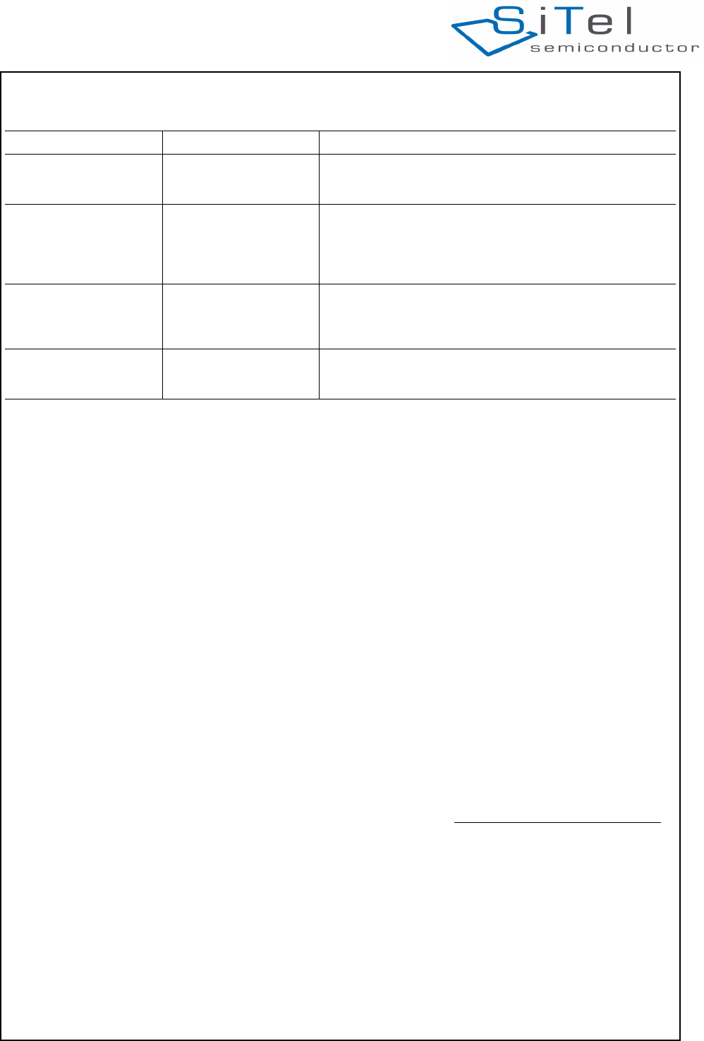
Life Support Policy
SiTel’S PRODUCTS ARE NOT AUTHORIZED FOR USE AS CIRTICAL COMPONENTS IN LIFE SUPPORT
DEVICES OR SYSTEMS WITHOUT THE EXPRESS WRITTEN APPROVAL OF THE PRESIDENT AND GENERAL
COUNSIL OF SiTel SEMICONDUCTOR. As used herein:
SC14CVMDECT Cordless Voice Module
© 2011 SiTel Semiconductor B.V. Company Confidential 45 August 19, 2011 v1.2.1
Product Status Definitions
SiTel Semiconductor reserves the right to make changes without notice to any products herein to improve reliability,
function or design. SiTel Semiconductor does not assume any liability arising out of the application or use of any
product or circuit described herein; neither does it convey any license under its patent rights, nor the right of others.
Datasheet Status Product Status Definition
Advance Information Formative or in Design This data sheet contains the design specifications for prod-
uct development. Specifications may change in any manner
without notice.
Preliminary First Production This data sheet contains preliminary data. Supplementary
data will be published at a later date. SiTel Semiconductor
reserves the right to make changes at any time without
notice in order to improve design and supply the best possi-
ble product.
No Identification Noted Full production This data sheet contains final specifications. SiTel Semicon-
ductor reserves the right to make changes at any time with-
out notice in order to improve design and supply the best
possible product.
Obsolete Not in Production This data sheet contains specifications on a product that has
been discontinued by SiTel Semiconductor. The data-sheet
is printed for reference information only.
1. Life support devices or systems are devices or
systems which,
(a) are intended for surgical implant into the
body, or (b) support or sustain life, and whose
failure to perform, when properly used in accord-
ance with instructions for use provided in the
labelling, can be reasonably expected to result
in a significant injury to the user.
2. A critical component is any component of a life
support device or system whose failure to per-
form can be reasonably expected to cause the
failure of the life support device or system, or to
affect its safety or effectiveness.
The Netherlands
SiTel Semiconductor B.V.
Phone: +31 73 640 88 22
SiTel Semiconductor does not assume any responsibility for use of any circuit described, no circuit patent licenses are implied, and SiTel
reserves the right, at any time without notice, to change said circuitry or specifications.
Contacting SiTel Semiconductor
RoHS Compliance
SiTel Semiconductor complies to DIRECTIVE 2002/95/EC OF THE EUROPEAN PARLIAMENT AND OF THE
COUNCIL of 27 January 2003 concerning Restriction of Hazardous Substances (RoHS).
SiTel Semiconductor statement on RoHS can be found on the customer portal http:/portal.SiTel-semiconductor.com.
RoHS certificates from our suppliers are available on request.
North America
SiTel North America
Phone: +1 408 727 3200
Japan
SiTel Semiconductor K. K.
Phone: +81 3 3769 8123
SiTel Semiconductor Japan
Short Range wireless & VoIP
Phone: +81 3 5408 4330
Singapore
SiTel Semiconductor Singapore
Phone: +65 64845419