Dialog Semiconductor SC14S DECT Module User Manual Rev 68 2959 01 Bx 101217

Dialog Semiconductor BV DECT Module Rev 68 2959 01 Bx 101217
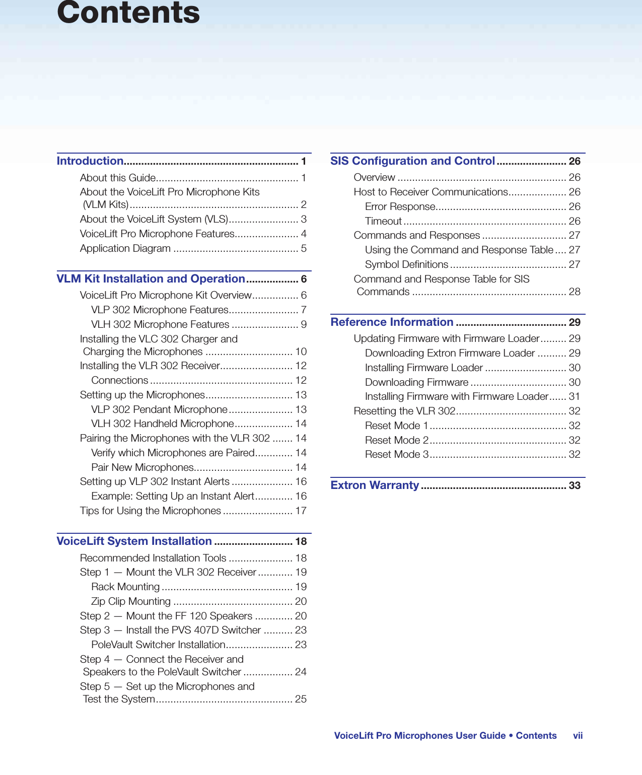
Contents

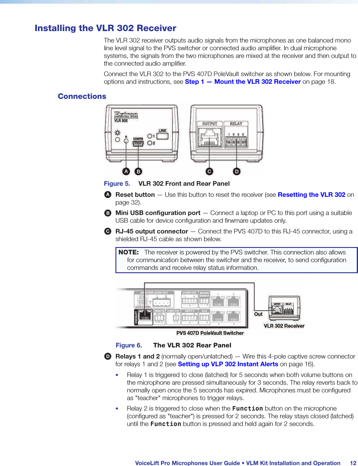
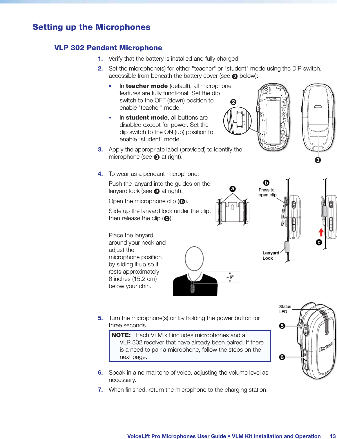
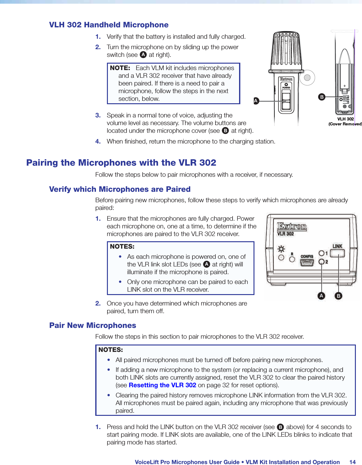
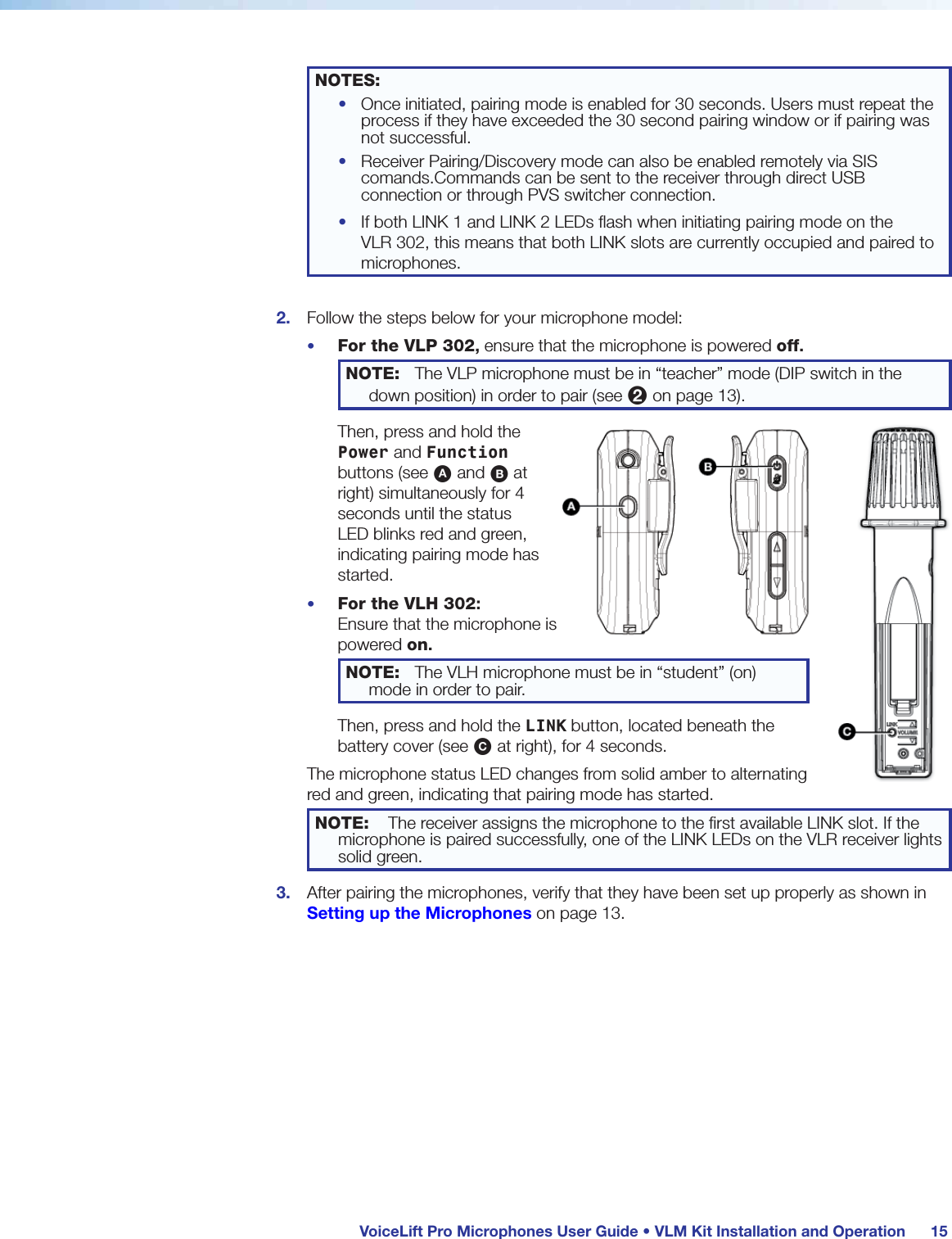
Rev_User Manual_68-2959-01_Bx_101217.pdf
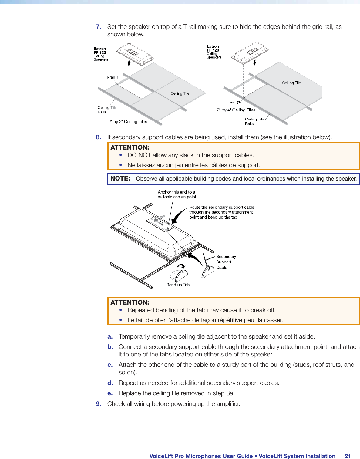
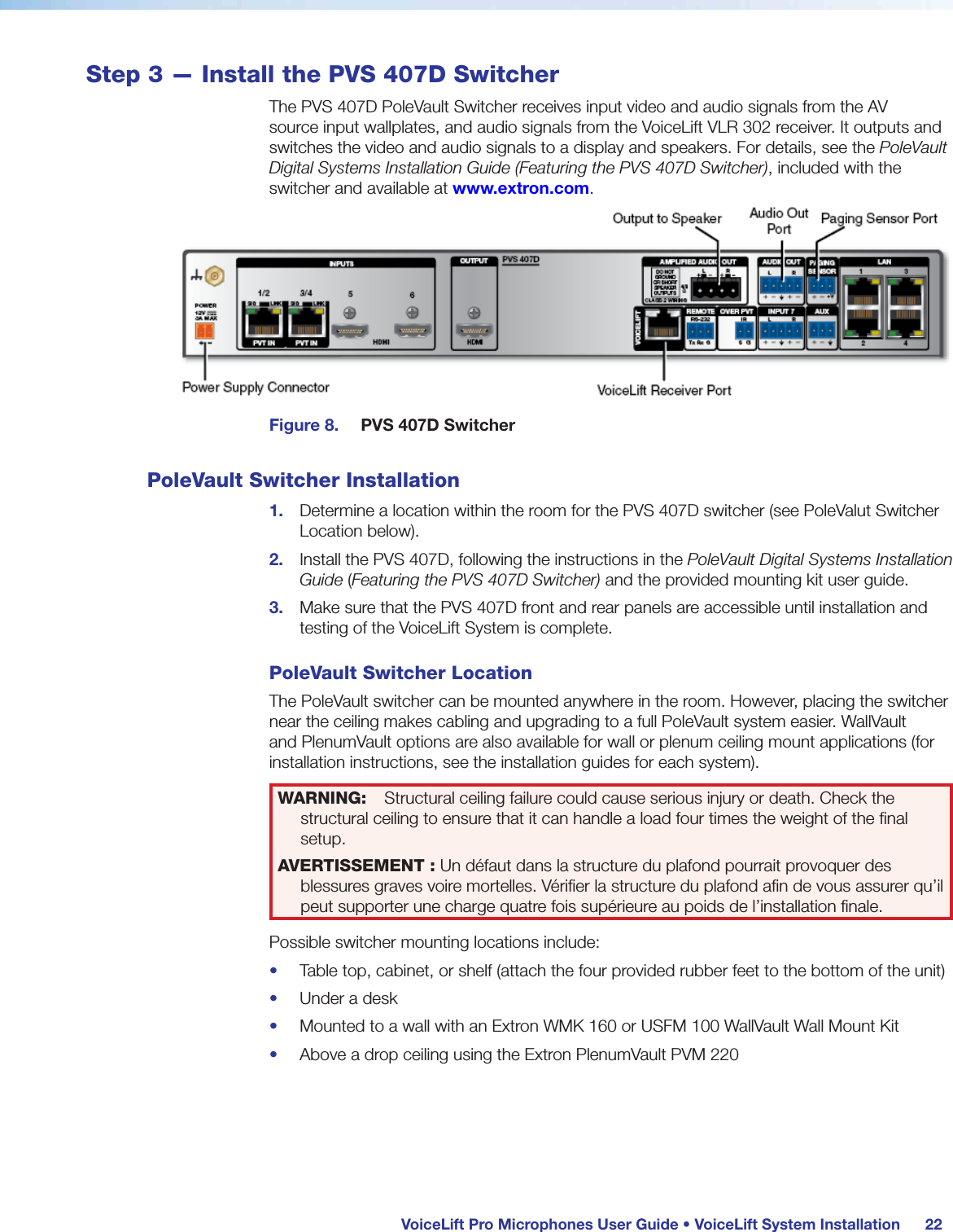
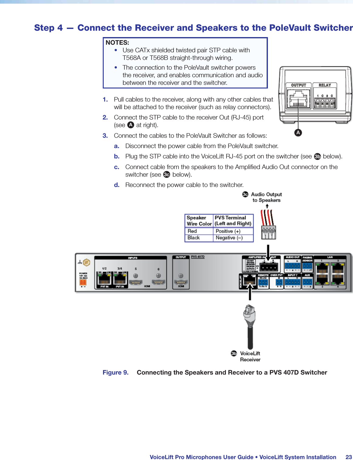
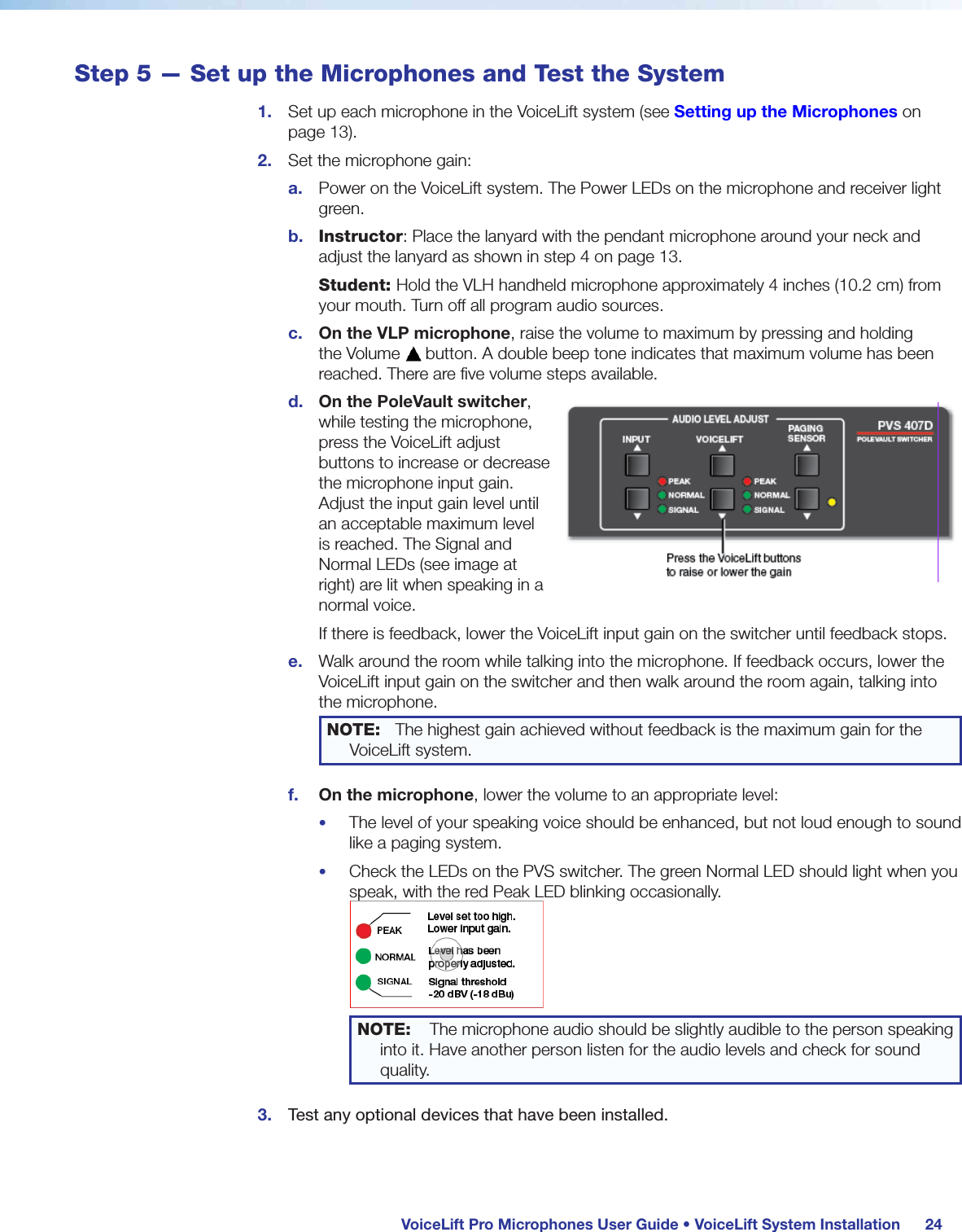
User GuideVoiceLift Pro  MicrophonesVoiceLiftVoiceLift Pro Microphone Kits (VLM) and  VoiceLift Pro Microphone Systems (VLS)Featuring the PVS 407D PoleVault Digital Switcher68-2959-01  Rev. Bx 10 17
Safety InstructionsSafety Instructions • EnglishWARNING:  This symbol,  , when used on the product, is intended to alert the user of the presence of uninsulated dangerous voltage within the product’s enclosure that may present a risk of electric shock.ATTENTION:  This symbol,  , when used on the product, is intended to alert the user of important operating and maintenance (servicing) instructions in the literature provided with the equipment.For information on safety guidelines, regulatory compliances, EMI/EMF compatibility, accessibility, and related topics, see the Extron Safety and Regulatory Compliance Guide, part number 68-290-01, on the Extron website, www.extron.com.Sicherheitsanweisungen • DeutschWARNUNG:  Dieses Symbol   auf dem Produkt soll den Benutzer darauf aufmerksam machen, dass im Inneren des Gehäuses dieses Produktes gefährliche Spannungen herrschen, die nicht isoliert sind und die einen elektrischen Schlag verursachen können.VORSICHT:  Dieses Symbol   auf dem Produkt soll dem Benutzer in der im Lieferumfang enthaltenen Dokumentation besonders wichtige Hinweise zur Bedienung und Wartung (Instandhaltung) geben.Weitere Informationen über die Sicherheitsrichtlinien, Produkthandhabung,  EMI/EMF-Kompatibilität, Zugänglichkeit und verwandte Themen finden Sie in den Extron-Richtlinien für Sicherheit und Handhabung  (Artikelnummer  68-290-01) auf der Extron-Website, www.extron.com.Instrucciones de seguridad • EspañolADVERTENCIA:  Este símbolo,  , cuando se utiliza en el producto, avisa al usuario de la presencia de voltaje peligroso sin aislar dentro del producto, lo que puede representar un riesgo de descarga eléctrica.ATENCIÓN:  Este símbolo,  , cuando se utiliza en el producto, avisa al usuario de la presencia de importantes instrucciones de uso y mantenimiento recogidas en la documentación proporcionada con el equipo.Para obtener información sobre directrices de seguridad, cumplimiento de normativas,  compatibilidad electromagnética, accesibilidad y temas relacionados, consulte la  Guía de cumplimiento de normativas y seguridad de Extron, referencia 68-290-01, en el sitio Web de Extron, www.extron.com.Instructions de sécurité • FrançaisAVERTISSEMENT :  Ce pictogramme,  , lorsqu’il est utilisé sur le produit, signale à l’utilisateur la présence à l’intérieur du boîtier du produit d’une tension électrique dangereuse susceptible de provoquer un choc électrique.ATTENTION :  Ce pictogramme,  , lorsqu’il est utilisé sur le produit, signale à l’utilisateur des instructions d’utilisation ou de maintenance importantes qui se trouvent dans la documentation fournie avec le matériel.Pour en savoir plus sur les règles de sécurité, la conformité à la réglementation, la compatibilité EMI/EMF, l’accessibilité, et autres sujets connexes, lisez les informations de sécurité et de conformité Extron, réf. 68-290-01, sur le site Extron, www.extron.com.Istruzioni di sicurezza • Italiano AVVERTENZA:  Il simbolo,  , se usato sul prodotto, serve ad avvertire l’utente della presenza di tensione non isolata pericolosa all’interno del contenitore del prodotto che può costituire un rischio di scosse elettriche.ATTENTZIONE:  Il simbolo,  , se usato sul prodotto, serve ad avvertire l’utente della presenza di importanti istruzioni di funzionamento e manutenzione nella documentazione fornita con l’apparecchio.Per informazioni su parametri di sicurezza, conformità alle normative, compatibilità EMI/EMF, accessibilità e argomenti simili, fare riferimento alla Guida alla conformità normativa e di sicurezza di Extron, cod. articolo 68-290-01, sul sito web di Extron, www.extron.com.Instrukcje bezpieczeństwa • Polska  OSTRZEŻENIE:  Ten symbol,  , gdy używany na produkt, ma na celu poinformować użytkownika o obecności izolowanego i niebezpiecznego napięcia wewnątrz obudowy produktu, który może stanowić zagrożenie porażenia prądem elektrycznym.UWAGI:  Ten symbol,  , gdy używany na produkt, jest przeznaczony do ostrzegania użytkownika ważne operacyjne oraz instrukcje konserwacji (obsługi) w literaturze, wyposażone w sprzęt.Informacji na temat wytycznych w sprawie bezpieczeństwa, regulacji wzajemnej zgodności, zgodność EMI/EMF, dostępności i Tematy pokrewne, zobacz Extron bezpieczeństwa i regulacyjnego zgodności przewodnik, część numer 68-290-01, na stronie internetowej Extron, www.extron.com.Инструкция по технике безопасности • РусскийПРЕДУПРЕЖДЕНИЕ:  Данный символ,  , если указан на продукте, предупреждает пользователя о наличии неизолированного опасного напряжения внутри корпуса продукта, которое может привести к поражению электрическим током.ВНИМАНИЕ:   Данный символ,  , если указан на продукте, предупреждает пользователя о наличии важных инструкций по эксплуатации и обслуживанию в руководстве, прилагаемом к данному оборудованию.Для получения информации о правилах техники безопасности, соблюдении нормативных требований, электромагнитной совместимости (ЭМП/ЭДС), возможности доступа и других вопросах см. руководство по безопасности и соблюдению нормативных требований Extron на сайте Extron: ,  www.extron.com, номер по каталогу - 68-290-01.安全说明 • 简体中文 警告:产品上的这个标志意在警告用户该产品机壳内有暴露的危险 电压,有触电危险。注意:产品上的这个标志意在提示用户设备随附的用户手册中有 重要的操作和维护(维修)说明。关于我们产品的安全指南、遵循的规范、EMI/EMF 的兼容性、无障碍 使用的特性等相关内容,敬请访问 Extron 网站 , www.extron.com,参见 Extron 安全规范指南,产品编号 68-290-01。
Copyright© 2017  Extron Electronics. All rights reserved.TrademarksAll trademarks mentioned in this guide are the properties of their respective owners.The following registered trademarks(®), registered service marks(SM), and trademarks(TM) are the property of RGBSystems, Inc. or ExtronElectronics (see the current list of trademarks on the Terms of Use page at www.extron.com):Registered Trademarks (®)Extron, Cable Cubby, ControlScript, CrossPoint, DTP, eBUS, EDID Manager, EDID Minder, Flat Field, FlexOS, Global Configurator, GlobalScripter, GlobalViewer, Hideaway, HyperLane, IPIntercom, IPLink, KeyMinder, LinkLicense, LockIt, MediaLink, MediaPort, NetPA, PlenumVault, PoleVault, PowerCage, PURE3, Quantum, SoundField, SpeedMount, SpeedSwitch, SystemINTEGRATOR, TeamWork, TouchLink, V-Lock, VideoLounge, VN-Matrix, VoiceLift, WallVault, WindoWall, XTP, and XTPSystemsRegistered Service Mark(SM) :  S3 Service Support SolutionsTrademarks (™)AAP, AFL (Accu-RateFrameLock), ADSP(Advanced Digital Sync Processing), Auto-Image, CableCover, CDRS(ClassD Ripple Suppression), Codec Connect, DDSP(Digital Display Sync Processing), DMI (DynamicMotionInterpolation), DriverConfigurator, DSPConfigurator, DSVP(Digital Sync Validation Processing), eLink, Entwine, EQIP, EverLast, FastBite, FOX, FOXBOX,  IP Intercom HelpDesk, MAAP, MicroDigital, Opti-Torque, ProDSP, QS-FPC(QuickSwitch Front Panel Controller), Room Agent, Scope-Trigger, ShareLink, Show Me, SIS, SimpleInstructionSet, Skew-Free, SpeedNav, StudioStation, Triple-Action Switching, True4K, Vector™ 4K , WebShare, XTRA, ZipCaddy, and ZipClip안전 지침 • 한국어 경고:   이 기호   가 제품에 사용될 경우, 제품의 인클로저 내에 있는 접지되지 않은 위험한 전류로 인해 사용자가 감전될 위험이 있음을 경고합니다.주의:  이 기호   가 제품에 사용될 경우, 장비와 함께 제공된 책자에 나와 있는 주요 운영 및 유지보수(정비) 지침을 경고합니다.안전 가이드라인, 규제 준수, EMI/EMF 호환성, 접근성, 그리고 관련 항목에 대한 자세한 내용은 Extron 웹 사이트(www.extron.com)의 Extron 안전 및 규제 준수 안내서, 68-290-01 조항을 참조하십시오. 安全記事 • 繁體中文 警告:若產品上使用此符號,是為了提醒使用者,產品機殼內存在著 可能會導致觸電之風險的未絕緣危險電壓。注意  若產品上使用此符號,是為了提醒使用者,設備隨附的用戶手冊中有重要的操作和維護(維修)説明。有關安全性指導方針、法規遵守、EMI/EMF 相容性、存取範圍和相關主題的詳細資訊,請瀏覽 Extron 網站:www.extron.com,然後參閱《Extron 安全性與法規遵守手冊》,準則編號 68-290-01。安全上のご注意 • 日本語 警告: この記号   が製品上に表示されている場合は、筐体内に絶縁されて いない高電圧が流れ、感電の危険があることを示しています。注意:この記号  が製品上に表示されている場合は、本機の取扱説明書に 記載されている重要な操作と保守(整備)の指示についてユーザーの注意を喚起するものです。安全上のご注意、法規厳守、EMI/EMF適合性、その他の関連項目に  つ い て は 、エ ク スト ロ ン の ウ ェブ サ イト  www.extron.com よ り  『 Extron Safety and Regulatory Compliance Guide』 ( P/N 68-290-01) をご覧ください。
 FCC Compliance StatementNOTE:  For more information on safety guidelines, regulatory compliances,  EMI/EMF compatibility, accessibility, and related topics, see the Extron Safety and Regulatory Compliance Guide on the Extron website.This device complies with Part 15 of the FCC Rules for portable devices only.Operation is subject to the following two conditions: (1) This device may not cause harmful interference, and (2) This device must accept any interference received, including interference that may cause undesired operation of the device.Changes or modifications to the equipment not expressly approved by Extron Electronics could void the user’s authority to operate the equipment.NOTE:  This equipment has been tested and found to comply with the limits for a ClassB digital device, pursuant to Part 15 of the FCC Rules. These limits are designed to provide reasonable protection against harmful interference in a residential installation.This equipment generates, uses and can radiate radio frequency energy and, if not installed and used in accordance with the instructions, may cause harmful interference to radio communications. However, there is no guarantee that interference will not occur in a particular installation.If this equipment does cause harmful interference to radio or television reception, which can be determined by turning the equipment off and on, the user is encouraged to try to correct the interference by one or more of the following measures:•  Reorient or relocate the receiving antenna•  Increase the separation between the equipment and receiver•  Connect the equipment into an outlet on a circuit different from that to which the receiver is connected.•  Consult the dealer or an experienced radio/TV technician for help.The VoiceLift Pro System has been tested/evaluated and found to comply with the FCC radiated exposure limits and meets the FCC radio frequency (RF) Exposure Guidelines.  The Receiver unit must be installed and operated keeping it at least 20cm away from the person’s body. The system must not be co-located or operating in conjunction with any other antenna or transmitter.
 Compliance ICCanada, Industry Canada (IC) NoticesCAN ICES-3 (B)/NMB-3(B)This device complies with Industry Canada licence-exempt RSS standard(s). Operation is subject to the following two conditions: (1) this device may not cause interference, and (2) this device must accept any interference, including interference that may cause undesired operation of the device. The VoiceLift Pro System has been tested/evaluated and found to comply with RSS 102 rf exposure limits and meets the ISED radio frequency (RF) Exposure Guidelines.  The Receiver unit must be installed and operated keeping it at least 20cm away from the person’s body. The system must not be co-located or operating in conjunction with any other antenna or transmitter. IC conformitéCanada, avis d’Industry Canada (IC) CAN ICES-3 (B)/NMB-3(B)Le présent appareil est conforme aux CNR d’Industrie Canada applicables aux appareils radio exempts de licence. L’exploitation est autorisée aux deux conditions suivantes : (1) l’appareil ne doit pas produire de brouillage, et (2) l’utilisateur de l’appareil doit accepter tout brouillage radioélectrique subi, même si le brouillage est susceptible d’en compromettre le fonctionnement. Le système de radiofréquence VoiceLift Pro a été testé et évalué, a été jugé en conformité avec les limites d’exposition aux radiofréquences CNR-102, et respecte les lignes directrices relatives à l’exposition aux radiofréquences de ISDEC. Le récepteur doit être installé et fonctionner en conservant une distance minimale de 20 cm entre l’appareil et le corps humain. Le système ne doit pas être placé à proximité ou fonctionner en association avec une autre antenne ou un autre émetteur.
 Conventions Used in this GuideNotificationsThe following notifications are used in this guide:CAUTION:  Risk of minor personal injury.ATTENTION :  Risque de blessuremineure.ATTENTION:  Attention indicates a situation that may damage or destroy the product or associated equipment. NOTE: A note draws attention to important information.Software CommandsCommands are written in the fonts shown here: ^AR Merge  Scene,,Op1  scene  1,1 ^B 51 ^W^C[01] R 0004 00300 00400 00800 00600 [02] 35 [17] [03]E X! *X1&* X2)* X2#* X2! CE}NOTE:  For commands and examples of computer or device responses mentioned in this guide, the character “0” is used for the number zero and “O” is the capital letter “o.”Computer responses and directory paths that do not have variables are written in the font shown here: Reply from 208.132.180.48: bytes=32 times=2ms TTL=32C:\Program Files\ExtronVariables are written in slanted form as shown here:ping xxx.xxx.xxx.xxx —tSOH R Data STX Command ETB ETXSelectable items, such as menu names, menu options, buttons, tabs, and field names are written in the font shown here:From the File menu, select New.Click the OK button. Specifications AvailabilityProduct specifications are available on the Extron website, www.extron.com.
viiVoiceLift Pro Microphones User Guide • ContentsContentsIntroduction............................................................ 1About this Guide ................................................. 1About the VoiceLift Pro Microphone Kits  (VLM Kits) .......................................................... 2About the VoiceLift System (VLS) ........................ 3VoiceLift Pro Microphone Features...................... 4Application Diagram ........................................... 5VLM Kit Installation and Operation .................. 6VoiceLift Pro Microphone Kit Overview ................ 6VLP 302 Microphone Features ........................ 7VLH 302 Microphone Features ....................... 9Installing the VLC 302 Charger and  Charging the Microphones .............................. 10Installing the VLR 302 Receiver......................... 12Connections ................................................. 12Setting up the Microphones .............................. 13VLP 302 Pendant Microphone ...................... 13VLH 302 Handheld Microphone .................... 14Pairing the Microphones with the VLR 302 ....... 14Verify which Microphones are Paired ............. 14Pair New Microphones.................................. 14Setting up VLP 302 Instant Alerts ..................... 16Example: Setting Up an Instant Alert ............. 16Tips for Using the Microphones ........................ 17VoiceLift System Installation ........................... 18Recommended Installation Tools ...................... 18Step 1 — Mount the VLR 302 Receiver ............ 19Rack Mounting ............................................. 19Zip Clip Mounting ......................................... 20Step 2 — Mount the FF 120 Speakers ............. 20Step 3 — Install the PVS 407D Switcher .......... 23PoleVault Switcher Installation ....................... 23Step 4 — Connect the Receiver and  Speakers to the PoleVault Switcher ................. 24Step 5 — Set up the Microphones and  Test the System ............................................... 25SIS Configuration and Control ........................ 26Overview .......................................................... 26Host to Receiver Communications .................... 26Error Response ............................................. 26Timeout ........................................................ 26Commands and Responses ............................. 27Using the Command and Response Table .... 27Symbol Definitions ........................................ 27Command and Response Table for SIS Commands ..................................................... 28Reference Information ...................................... 29Updating Firmware with Firmware Loader ......... 29Downloading Extron Firmware Loader .......... 29Installing Firmware Loader ............................ 30Downloading Firmware ................................. 30Installing Firmware with Firmware Loader ...... 31Resetting the VLR 302 ...................................... 32Reset Mode 1 ............................................... 32Reset Mode 2 ............................................... 32Reset Mode 3 ............................................... 32Extron Warranty .................................................. 33
 viii
VoiceLift Pro Microphones User Guide • Introduction 1IntroductionThis section covers the following topics:•  About this Guide•  About the VoiceLift Pro Microphone Kits•  About the VoiceLift System•  VoiceLift Pro Microphone Features•  Application DiagramAbout this GuideThis guide describes the components, installation, and operation of the Extron VoiceLift Pro Microphone Kit and the VoiceLift System.•  VoiceLift Pro Microphone Kits (VLM kit) include the pendant or handheld microphones, the receiver, and the charging station (see About the VoiceLift Pro Microphone Kits on the next page for details).NOTE:  VoiceLift Pro Microphone Kits can be part of a VoiceLift System or can be installed and used within a new or existing PoleVault, WallVault, or PlenumVault System.•  VoiceLift Systems (VLS) include a microphone kit, a PVS 407D switcher, and FF 120 Flat Field Speakers (see About the VoiceLift System on page 3 for details).CAUTION:  Risk of explosion. Do not replace the battery with an incorrect type. Dispose of used batteries according to the instructions.ATTENTION :  Risque d’explosion. Ne pas remplacer la pile par le mauvais type de pile. Débarrassez-vous des piles usagées selon le mode d’emploi.ATTENTION:•  Installation and service must be performed by authorized personnel only. •  L’installation et l’entretien doivent être effectués par le personnel autorisé uniquement.  •  UL listed electrical boxes are recommended.•  Des boîtiers électriques approuvés UL sont recommandés. The following terms are used in this guide:•  “Microphone” refers to the VLP 302 or VLH 302.•  “Receiver” refers to the VLR 302 receiver. The receiver can be mounted into Extron enclosures or can be rack mounted. One receiver can host up to two microphones. •  “Charging station” refers to the VLC 302 charger for dual microphones (VLP or VLH). •  “PoleVault switcher” refers to the PVS 407D PoleVault switcher. For details about the PVS 407D Switcher, see the PVS 407D PoleVault Digital Switcher User Guide.
 VoiceLift Pro Microphones User Guide • Introduction 2About the VoiceLift Pro Microphone Kits (VLM Kits)A VoiceLift Pro Microphone Kit is a classroom microphone amplification system that enables a teacher or presenter to be clearly heard at a comfortable level throughout the entire room. There are three types of VoiceLift VLM kits available:•  VLM 3001 includes: One VLP 302 pendant microphone, a VLR 302 receiver, and a VLC 302 charging station.•  VLM 3002 includes: Two pendant microphones (VLP 302), a VLR 302 receiver, and a VLC 302 charging station.•  VLM 3002H includes: One VLP 302 pendant microphone, one VLH 302 handheld microphone, a VLR 302 receiver, and a VLC 302 charging station.NOTES: •  A VLM kit can be integrated into an existing PoleVault, WallVault, or PlenumVault System. For details about integrating a VLM kit into an existing system, see the PoleVault Digital Systems (featuring the PVS 407D) Installation Guide (included with the installed system and also available at www.extron.com).•  If any items in the VLM kit are damaged or missing, contact the Extron S3  Sales & Technical Support Hotline.
 VoiceLift Pro Microphones User Guide • Introduction 3About the VoiceLift System (VLS)The VoiceLift System consists of a VLM kit, a PoleVault switcher, and two FF 120 speakers.There are three types of VoiceLift Systems:•  VLS 3001 contains:  The VLM 3001 kit, a PVS 407D PoleVault switcher, and two FF 120 speakers.•  VLS 3002 contains:  The VLM 3002 kit, a PVS 407D PoleVault switcher, and two FF 120 speakers.•  VLS 3002H contains: The VLM 3002H kit, a PVS 407D PoleVault switcher, and two FF 120 speakers.A VoiceLift system can operate in either single or dual microphone configurations. Dual microphones (typically assigned as Instructor and Student microphones) may be used individually or simultaneously (see VoiceLift Pro Microphone Kit Overview on page 6 for more information).NOTE:  If any VoiceLift System items are damaged or missing, contact the Extron S3  Sales & Technical Support Hotline.
 VoiceLift Pro Microphones User Guide • Introduction 4VoiceLift Pro Microphone Features•  Lightweight microphones — The microphones are made of lightweight and  impact-resistant polycarbonate material. The VLP 302 pendant microphone can be worn comfortably around the neck or clipped to clothing. The VLH 302 can be used for multiple presenters and as a student pass-around microphone.•  Built-in DSP — The receiver has an integrated digital signal processor (DSP) that maximizes sound quality and intelligibility.•  Two microphones per classroom — An installed VoiceLift System supports up to two microphones in each classroom and can be used by instructors and students.•  Power switch — The VLP 302 pendant microphone has an easily accessible switch on the side to mute the sound and power the microphone on and off. The VLH has a sliding switch which toggles the microphone on and off.•  Volume buttons — Volume buttons on the VLP 302 are conveniently located, enabling the presenter to easily raise and lower the volume during use. Volume buttons on the VLH 302 are hidden within the battery compartment.•  Instant alert e-mail messaging — The VoiceLift receiver can be configured to allow the teacher to send e-mail alerts, if needed, by pressing the VLP microphone Volume buttons (see D Relays 1 and 2 on page 12 and Setting up VLP 302 Instant Alerts on page 16 for details).•  Auxiliary microphone input (VLP 302) allows use of an optional lavalier or headset microphone.•  Auxiliary audio input (VLH 302) for an external audio source, such as an MP3 player.•  Battery power — The VLP 302 and VLH 302 microphones are powered by a single NiMh or alkaline AA battery. NiMh batteries can be recharged in the VLC 302 charging station.•  VLC 302 charging station — Holds and recharges up to two microphones.•  Receiver mounting options — The VLR 302 receiver is compact and can be mounted within Extron enclosures or can be rack mounted.
 VoiceLift Pro Microphones User Guide • Introduction 5Application DiagramThe application diagram below shows a typical classroom installation incorporating the VoiceLift System.Figure 1.  Typical Room Installation
VoiceLift Pro Microphones User Guide • VLM Kit Installation and Operation 6VLM Kit Installation and OperationThis section covers the following topics:•  VoiceLift Pro Microphone Kit Overview•  Installing the VLC 302 Charger and Charging the Microphones•  Installing the VLR 302 Receiver•  Setting up the Microphones•  Pairing the Microphones with the VLR 302•  Setting up VLP 302 Instant Alerts•  Tips for Using the MicrophonesVoiceLift Pro Microphone Kit OverviewThe figure below shows the path of the audio signal through the VoiceLift System.Figure 2.  VoiceLift System Audio Signal PathA VLP or VLH Microphone — The VLP 302 and VLH 302 microphone transmits the voice audio signal to the VLR 302 receiver.B VLR 302 Receiver — The VLR 302 receives the signal from the microphone, and outputs a balanced mono line level signal (-10 dBV) to the PoleVault switcher.C PoleVault switcher — The PVS 407D PoleVault switcher functions as an amplifier for the VoiceLift System. It amplifies the audio signal from the VLR 302 receiver and sends it to the speakers. The switcher powers speakers placed throughout the room to improve the signal-to-noise ratio of the voice to at least +15 dB.
 VoiceLift Pro Microphones User Guide • VLM Kit Installation and Operation 7VLP 302 Microphone FeaturesFigure 3.  VLP 302 Microphone FeaturesA — Status LED (tri-color)B — Microphone acoustic portsC — Auxiliary microphone input (3.5 mm           mono female input jack) D — Function buttonE — Spring ClipF — Microphone identification           label recessG — Power/mute buttonH — Volume   button (increase) I — Volume   button (decrease)J — Charging contactsA Status LED — This LED indicates the microphone power, volume, and charging status as follows:LED indicators when the microphone is powered on and in use:LED Color IndicationLED off Microphone is OFF or battery not installedGreen – steady Microphone ONGreen –  slow blinking Microphone mutedGreen –  single blink Volume adjusted (increased or decreased)Red –  slow blinking Low battery (30 minutes or less of talk time left).  Recharge battery.Red –  steady Battery life depleted. Recharge battery.Red –  steady (5 seconds) Instant Alert activated. Volume Up and Down buttons pressed and held simultaneously for 3 seconds (relay 1 triggered). LED and relay revert states after 5 seconds.Amber (flashes for 5 seconds) Function button activated.   Function button was pressed and held for 2 seconds (relay 2 is triggered and latches to opposite state).Red and green – alternate blinking Microphone in discovery mode and attempting to pair with receiverLED indicators when the microphone is charging:LED Color IndicationRed – steady Battery chargingGreen – steady Battery fully chargedRed and green – alternate blinking Incompatible, faulty or failed battery detected. Replace battery.B Microphone acoustic audio input ports — The microphone receives voice audio through these two acoustical ports. Do not block these ports while the microphone is in use.
 VoiceLift Pro Microphones User Guide • VLM Kit Installation and Operation 8C Auxiliary microphone input (Audio In) — Connect an auxiliary lavalier microphone into this 3.5 mm mono auxiliary mic input jack. When an external lavalier microphone is connected, the built in microphone elements in the VLP 302 are disabled.D Function button — When this button is pressed and held for two seconds, the microphone signals the receiver to toggle Relay 2 to its opposite state.   NOTE:  The status LED flashes amber for 5 seconds, indicating that the relay has been toggled.Also, when this button is pressed simultaneously with the Power button, it initiates Link (pairing) mode.E  Spring clip — Use this clip to attach the VLP 302 to clothing or to a lanyard (included) (see step 4 on page 13 for instructions). The lanyard lock is used to retain proper position of the microphone when clipped to the lanyard. The breakaway clasps help to release the lanyard from around the neck if it is pulled tightly. Place this clasp at the back of your neck when wearing the pendant microphone.F Microphone identification label recess — Place the appropriate provided sticker in this space to identify the microphone user (see step 3 on page 13).G Power and mute button (Off/Mute/On) — Press and hold the Power button (for three seconds) to power the microphone on or off.  With the device on, press and release this button momentarily to mute or unmute the microphone.HI Volume buttons — Raise or lower the microphone volume. Pressing and holding both of these buttons simultaneously for 3 seconds sends a signal to the receiver to close its Relay 1 port. This is typically used to trigger an alert (see Setting up VLP 302 Instant Alerts on page 16).J Charging contacts — These make contact with the contacts in the charging station when placed into the VLC 302. A full charge can take up to 5 hours.
 VoiceLift Pro Microphones User Guide • VLM Kit Installation and Operation 9VLH 302 Microphone FeaturesFigure 4.  VLH 302 Microphone FeaturesA Power Switch — Slide up to power on and down to power off.B Power Status LED — Dual color LED (green and red) indicates power or Link status. LED indicators when the microphone is powered on and in use:LED Color IndicationLED off Microphone is OFF or battery is not installed.Green – steady Microphone ON and paired to receiverGreen –  single blink Volume adjusted (increased or decreased).Red –  slow blinking Low battery (30 minutes or less of talk time left). Recharge battery.Red –  steady Battery life depleted. Recharge batteryRed and green – alternating blinkMicrophone in discovery mode and attempting to pair with receiver.LED indicators when the microphone is charging:LED Color IndicationRed – steady Battery chargingGreen – steady Battery fully chargedRed and green – alternating blinkIncompatible, faulty, or failed battery detected. Check and replace battery.C Auxiliary Stereo Audio Input — 3.5 mm stereo input accepts line level audio signals, but does not support external lavalier/lapel microphones. When an active aux input device is connected, the built in microphone is disabled. The audio from the auxiliary audio source is summed to mono and transmitted to the receiver.D Link button — This button is used to enable pairing mode.EF Volume buttons — Increase ( ) or decrease ( ) the microphone volume.
 VoiceLift Pro Microphones User Guide • VLM Kit Installation and Operation 10Installing the VLC 302 Charger and Charging the MicrophonesThe VLC 302 charges the microphone battery. It is powered by an external wall power supply (provided). The microphone battery requires up to 5 hours to charge fully. It is safe to charge for extended periods, but Extron recommends storing the microphone out of the charger with the battery removed.NOTES: •  The charging station is to be used with NiMH rechargeable batteries only.•  Fully charge the supplied batteries before first use.Follow these steps to connect the charger and charge the microphones.1.  Connect the 5 VDC, 2.6 A wall charger from a 110-130 VAC (U.S.) or a  100-240 VAC (international), 50-60 Hz power source, to the mini B USB adapter.2.  Connect the USB mini plug end of the adapter to the USB mini jack located on the back of the VLC 302 (see 2 at right).    3.  To install the battery, remove the microphone battery cover as follows:•  VLP 302: Unscrew the two rear panel screws located on either side of the rear clip.•  VLH 302: Slide the battery cover downward until it stops, then lift the cover up and off the microphone.Insert the battery, aligning the + and – poles as indicated inside the compartment. CAUTION:   Use only NiMH rechargeable batteries provided by Extron when charging the microphone. Use of any rechargeable battery other than the type provided by Extron may cause explosion, chemical leakage, and injury.ATTENTION :  Utilisez uniquement les piles rechargeables de type NiMH fournies par Extron, lorsque vous rechargez le microphone. L’utilisation d’une pile rechargeable différente du type fourni par Extron peut présenter un risque d’explosion, de fuite de substances chimiques, ou de blessure.ATTENTION:  Be sure to replace the battery with the correct type and to dispose of used batteries appropriately.ATTENTION:  Assurez vous de remplacer les piles par le bon modèle et de jeter les piles usagées de façon appropriée.
 VoiceLift Pro Microphones User Guide • VLM Kit Installation and Operation 114.  Insert the microphone into one of the charger slots (4). The microphone LED turns red when the microphone is charging.LED Color IndicationRed – steady Battery chargingGreen – steady Battery fully chargedRed and green – alternate blinkingIncompatible or failed battery detected. Check and replace battery.NOTES: •  The microphone battery requires up to 5 hours to charge fully. It is safe to charge for extended periods, but Extron recommends storing the microphone out of the charger with the battery removed.•  Make sure that the microphones are fully seated in the charging station to ensure proper charging.ATTENTION:•  Do not charge alkaline batteries.•  Ne rechargez pas les piles alcalines.•  Use only Extron provided LPS type power supply charger for charging.•  Veuillez utiliser uniquement le bloc d’alimentation de type LPS fourni par Extron pour la recharge.
 VoiceLift Pro Microphones User Guide • VLM Kit Installation and Operation 12Installing the VLR 302 ReceiverThe VLR 302 receiver outputs audio signals from the microphones as one balanced mono line level signal to the PVS switcher or connected audio amplifier. In dual microphone systems, the signals from the two microphones are mixed at the receiver and then output to the connected audio amplifier. Connect the VLR 302 to the PVS 407D PoleVault switcher as shown below. For mounting options and instructions, see Step 1 — Mount the VLR 302 Receiver on page 18.ConnectionsFigure 5.  VLR 302 Front and Rear PanelA Reset button — Use this button to reset the receiver (see Resetting the VLR 302 on page 32).B Mini USB configuration port — Connect a laptop or PC to this port using a suitable USB cable for device configuration and firwmare updates only.C RJ-45 output connector — Connect the PVS 407D to this RJ-45 connector, using a shielded RJ-45 cable as shown below.NOTE:  The receiver is powered by the PVS switcher. This connection also allows for communication between the switcher and the receiver, to send configuration commands and receive relay status information.Figure 6.  The VLR 302 Rear PanelD Relays 1 and 2 (normally open/unlatched) — Wire this 4-pole captive screw connector for relays 1 and 2 (see Setting up VLP 302 Instant Alerts on page 16).•  Relay 1 is triggered to close (latched) for 5 seconds when both volume buttons on the microphone are pressed simultaneously for 3 seconds. The relay reverts back to normally open once the 5 seconds has expired. Microphones must be configured as "teacher" microphones to trigger relays.•  Relay 2 is triggered to close when the Function button on the microphone (configured as "teacher") is pressed for 2 seconds. The relay stays closed (latched) until the Function button is pressed and held again for 2 seconds.
 VoiceLift Pro Microphones User Guide • VLM Kit Installation and Operation 13Setting up the MicrophonesVLP 302 Pendant Microphone1.  Verify that the battery is installed and fully charged.2.  Set the microphone(s) for either "teacher" or "student" mode using the DIP switch, accessible from beneath the battery cover (see 2 below):•  In teacher mode (default), all microphone features are fully functional. Set the dip switch to the OFF (down) position to enable “teacher” mode. •  In student mode, all buttons are disabled except for power. Set the dip switch to the ON (up) position to enable “student” mode.3.  Apply the appropriate label (provided) to identify the microphone (see 3 at right). 4.  To wear as a pendant microphone:Push the lanyard into the guides on the lanyard lock (see a at right).Open the microphone clip (b).Slide up the lanyard lock under the clip, then release the clip (c). Place the lanyard around your neck and adjust the  microphone position by sliding it up so it rests approximately 6 inches (15.2 cm)  below your chin.   5.  Turn the microphone(s) on by holding the power button for  three seconds. NOTE:  Each VLM kit includes microphones and a  VLR 302 receiver that have already been paired. If there is a need to pair a microphone, follow the steps on the next page.6.  Speak in a normal tone of voice, adjusting the volume level as necessary. 7.  When finished, return the microphone to the charging station.23
 VoiceLift Pro Microphones User Guide • VLM Kit Installation and Operation 14VLH 302 Handheld Microphone1.  Verify that the battery is installed and fully charged.2.  Turn the microphone on by sliding up the power switch (see A at right).NOTE:  Each VLM kit includes microphones and a VLR 302 receiver that have already been paired. If there is a need to pair a microphone, follow the steps in the next section, below.3.  Speak in a normal tone of voice, adjusting the volume level as necessary. The volume buttons are located under the microphone cover (see B at right).4.  When finished, return the microphone to the charging station.Pairing the Microphones with the VLR 302Follow the steps below to pair microphones with a receiver, if necessary.Verify which Microphones are PairedBefore pairing new microphones, follow these steps to verify which microphones are already paired:1.  Ensure that the microphones are fully charged. Power each microphone on, one at a time, to determine if the microphones are paired to the VLR 302 receiver.NOTES: •  As each microphone is powered on, one of the VLR link slot LEDs (see A at right) will illuminate if the microphone is paired.•  Only one microphone can be paired to each LINK slot on the VLR receiver.2.  Once you have determined which microphones are paired, turn them off.Pair New MicrophonesFollow the steps in this section to pair microphones to the VLR 302 receiver.NOTES: •  All paired microphones must be turned off before pairing new microphones.•  If adding a new microphone to the system (or replacing a current microphone), and both LINK slots are currently assigned, reset the VLR 302 to clear the paired history (see Resetting the VLR 302 on page 32 for reset options).•  Clearing the paired history removes microphone LINK information from the VLR 302. All microphones must be paired again, including any microphone that was previously paired.1.  Press and hold the LINK button on the VLR 302 receiver (see B above) for 4 seconds to start pairing mode. If LINK slots are available, one of the LINK LEDs blinks to indicate that pairing mode has started.
 VoiceLift Pro Microphones User Guide • VLM Kit Installation and Operation 15NOTES: •  Once initiated, pairing mode is enabled for 30 seconds. Users must repeat the process if they have exceeded the 30 second pairing window or if pairing was not successful.•  Receiver Pairing/Discovery mode can also be enabled remotely via SIS comands.Commands can be sent to the receiver through direct USB connection or through PVS switcher connection.•  If both LINK 1 and LINK 2 LEDs flash when initiating pairing mode on the  VLR 302, this means that both LINK slots are currently occupied and paired to microphones.2.  Follow the steps below for your microphone model:•  For the VLP 302, ensure that the microphone is powered off.  NOTE:  The VLP microphone must be in “teacher” mode (DIP switch in the down position) in order to pair (see 2 on page 13).Then, press and hold the Power and Function buttons (see A and B at right) simultaneously for 4 seconds until the status LED blinks red and green, indicating pairing mode has started.•  For the VLH 302: Ensure that the microphone is powered on. NOTE:  The VLH microphone must be in “student” (on) mode in order to pair.Then, press and hold the LINK button, located beneath the battery cover (see C at right), for 4 seconds.The microphone status LED changes from solid amber to alternating red and green, indicating that pairing mode has started.NOTE:  The receiver assigns the microphone to the first available LINK slot. If the microphone is paired successfully, one of the LINK LEDs on the VLR receiver lights solid green.3.  After pairing the microphones, verify that they have been set up properly as shown in Setting up the Microphones on page 13.
 VoiceLift Pro Microphones User Guide • VLM Kit Installation and Operation 16Tips for Using the Microphones•  Speak in a normal tone of voice. When the microphone is set up properly, voice audio is amplified just above ambient room noise.•  Mute or turn the microphone off while having private conversations.•  Return the microphones to the charging station when not in use. Verify that the microphones are fully seated in the VLC 302 charger to ensure batteries are charged.•  If you are experiencing intermittent audio problems, check the batteries and replace them if necessary. NiMH and alkaline batteries are supported.CAUTION: Do not replace the battery with an incorrect type. Use only NiMh or alkaline batteries.ATTENTION : Ne pas remplacer la pile par le mauvais type de pile. Utilisez seulement des piles de type NiMh ou alkaline.ATTENTION:•  Do not recharge alkaline batteries.•  Ne rechargez pas les piles alkalines.•  Dispose of used batteries according to the instructions provided on the battery packaging.•  Débarrassez-vous des piles utilisées selon les instructions du fabricant.
VoiceLift Pro Microphones User Guide • VoiceLift System Installation 17VoiceLift System InstallationThis section provides instructions for installing the VoiceLift System (VLS). Topics include:•  Recommended Installation Tools•  Step 1 — Mount the VLR 302 Receiver•  Step 2 — Mount the FF 120 Speakers•  Step 3 — Install the PVS 407D Switcher•  Step 4 — Connect the Receiver and Speakers to the Switcher•  Step 5 — Set up the Microphones and Test the SystemRecommended Installation ToolsThe following tools are recommended to complete the installation.•  Laser level, or two levels (large level for screen installation; small level for wall plates and projector mounts)•  Tape measure•  Stud finder•  Drill and drill bit set, including a unibit to cut through metal studs•  Extension drill bit (3/4 inch min., 4 to 8 foot length, to drill through fire breaks)•  Socket set•  Pipe strap or wrapped pipe wrench•  Pliers and wire strippers•  Standard screwdriver set and Extron Tweeker•  Cable cutters (to cut safety wire)•  Drywall saw and hacksaw blade mounted on handle (for cutting ceiling tiles)•  Flashlight and safety goggles•  Razor knife•  2 inch hole saw•  Painter’s tape (to mark up walls), pencil, and marker pen•  RJ-45 crimpers and RJ-45 connectors•  Voltage tester•  Fish tape, pull string, and electrical tape (for taping fish tape to pull string)•  Zip ties•  Vacuum cleaner•  Heat gunOther Hardware ItemsSome or all of the following installation hardware may be needed for the installation at your particular site (may vary by installation):•  Electrical ceiling box•  Junction box•  Plaster ring•  Raceway•  Bolts for concrete structural ceilings where needed•  Drywall anchors and screws•  Spare ceiling tiles in case of accidental damage during installation•  Safety wire, lag eye bolts, and strain reliefs•  Heat shrink•  Extension cord
 VoiceLift Pro Microphones User Guide • VoiceLift System Installation 18Step 1 — Mount the VLR 302 ReceiverRack MountingThe receiver includes 1/8 rack mounting holes for mounting directly to a rack shelf or architectural enclosure that supports standard Extron mounting hole patterns.UL Guidelines for Rack MountingThe following Underwriters Laboratories (UL) guidelines are relevant to the safe installation of this product in a rack:•  Elevated operating ambient temperature — If the unit is installed in a closed or multi-unit rack assembly, the operating ambient temperature of the rack environment may be greater than room ambient temperature. Therefore, install the equipment in an environment compatible with the maximum ambient temperature  (TMA = +122 °F, +50°C) specified by Extron.•  Reduced air flow — Install the equipment in the rack so that safe operation and adequate air flow is provided to the unit.•  Mechanical loading — Mount the equipment in the rack so that a hazardous condition is not achieved due to uneven mechanical loading.•  Circuit overloading — Connect the equipment to the supply circuit and consider the effect that circuit overloading might have on overcurrent protection and supply wiring. Consider the equipment nameplate ratings when addressing this concern.•  Reliable earthing (grounding) — Maintain reliable grounding of rack-mounted equipment. Pay particular attention to supply connections other than direct connections.Rack Mounting ProcedureThe receiver can be mounted on optional rack systems listed on the website (see www.extron.com). To mount the unit on a rack shelf, follow the instructions provided with the shelf accessories.Back of the Rack Mounting ProcedureThe receiver can be mounted to the rear of a rack using an optional back of rack mounting kit (see www.extron.com). The kit allows the product to be vertically mounted to the front or rear rack supports and face either the front or the rear of the rack. To mount the unit, follow the instructions provided with the kit.The VLR 302 can be mounted within the USFM 100, WMK 160 and PVM 220, as shown below (see the PoleVault Digital System Installation Guide for details).Figure 7.  VLR 302 Rack Mounting Options
 VoiceLift Pro Microphones User Guide • VoiceLift System Installation 19Zip Clip MountingUsing the ZipClip 100 (optional)To attach the receiver to the ZipClip 100 mounting clip:1.  Insert the bottom of the receiver down into the  clip, starting with one end.2.  Pivot the other end down and press until  the clip snaps into place.To remove the receiver from the ZipClip:1.  Press the tab on the ZipClip.2.  Pivot the receiver and lift it out of the ZipClip.To fasten the tie wraps for cable strain relief:1.  Attach the receiver to the ZipClip 100 mounting clip as described previously.2.  Fasten the cables to the ZipClip base.a.  Insert tie wraps (“zip ties”) along the notches on the side of the receiver and through the tie wrap anchor points on the ZipClip, then around the cord.b.  Connect and pull the tie wraps until they are secure. Do not over tighten.Step 2 — Mount the FF 120 SpeakersThe FF 120 speakers are installed in ceiling tiles. They receive and output the audio signal from the PVS 407D switcher. Follow the steps below to install the FF 120 speakers.NOTE:  The installation must conform to national and local electrical codes and UL requirements (see the FF 120 Flat Field Speakers User Guide for details).1.  Remove and cut ceiling tile — Remove the ceiling tile where the FF 120 will be installed. Cut out a 12-inch section from either end of the tile where the speaker will be installed, as shown at right.      2.  Install the T-rail  — Install the T-rail crosspiece into the ceiling opening up against the cut tile, as shown at right.
 VoiceLift Pro Microphones User Guide • VoiceLift System Installation 203.  Cover plate  — Loosen, but do not remove, the two screws on the top of the cover plate, as shown on the right. Next, slide and remove the cover plate.        4.  Using Flexible Conduit  — When using flexible conduit, insert the conduit into the cover plate opening using an appropriate conduit adapter, and secure the conduit adapter to the plate, as shown at right.    When using speaker wires without a conduit, secure the cable clamp adapter (included)  to the cover plate and insert the wires through the clamp. Tighten the screws, as shown  below.        5.  Wire the speaker —a.  Pull the wires from the amplifier through and out of the conduit, if a conduit is used.b.  Route the two wires from the amplifier through the cover plate hole. See the wire gauge table on page 1.c.  Strip 3/16 inch (5 mm) from the ends of the two speaker wire leads (+ and -) coming from the amplifier. Keep the wire strands together by twisting them (do not tin the wires), and secure the wires to the input terminals of the speaker while observing the correct polarity.d.  Connect the red, positive (+) wire to the + speaker terminal and connect the black, negative (-) wire to the - speaker terminal, as shown at right.   6.  Replace the cover plate and tighten the two cover plate screws that were loosened in step 3.Cable Clamp AdapterCover PlateSecondary Attachment PointRear of Speaker
 VoiceLift Pro Microphones User Guide • VoiceLift System Installation 217.  Set the speaker on top of a T-rail making sure to hide the edges behind the grid rail, as shown below.8.  If secondary support cables are being used, install them (see the illustration below).ATTENTION: •  DO NOT allow any slack in the support cables.•  Ne laissez aucun jeu entre les câbles de support.NOTE: Observe all applicable building codes and local ordinances when installing the speaker.ATTENTION: •  Repeated bending of the tab may cause it to break off.•  Le fait de plier l’attache de façon répétitive peut la casser.a.  Temporarily remove a ceiling tile adjacent to the speaker and set it aside.b.  Connect a secondary support cable through the secondary attachment point, and attach it to one of the tabs located on either side of the speaker. c.  Attach the other end of the cable to a sturdy part of the building (studs, roof struts, and so on).d.  Repeat as needed for additional secondary support cables.e.  Replace the ceiling tile removed in step 8a.9.  Check all wiring before powering up the amplifier.
 VoiceLift Pro Microphones User Guide • VoiceLift System Installation 22Step 3 — Install the PVS 407D SwitcherThe PVS 407D PoleVault Switcher receives input video and audio signals from the AV source input wallplates, and audio signals from the VoiceLift VLR 302 receiver. It outputs and switches the video and audio signals to a display and speakers. For details, see the PoleVault Digital Systems Installation Guide (Featuring the PVS 407D Switcher), included with the switcher and available at www.extron.com.Figure 8.  PVS 407D SwitcherPoleVault Switcher Installation1.  Determine a location within the room for the PVS 407D switcher (see PoleValut Switcher Location below).2.  Install the PVS 407D, following the instructions in the PoleVault Digital Systems Installation Guide (Featuring the PVS 407D Switcher) and the provided mounting kit user guide.3.  Make sure that the PVS 407D front and rear panels are accessible until installation and testing of the VoiceLift System is complete.PoleVault Switcher LocationThe PoleVault switcher can be mounted anywhere in the room. However, placing the switcher near the ceiling makes cabling and upgrading to a full PoleVault system easier. WallVault and PlenumVault options are also available for wall or plenum ceiling mount applications (for installation instructions, see the installation guides for each system).WARNING:  Structural ceiling failure could cause serious injury or death. Check the structural ceiling to ensure that it can handle a load four times the weight of the final setup.AVERTISSEMENT : Un défaut dans la structure du plafond pourrait provoquer des blessures graves voire mortelles. Vérifier la structure du plafond afin de vous assurer qu’il peut supporter une charge quatre fois supérieure au poids de l’installation finale.Possible switcher mounting locations include:•  Table top, cabinet, or shelf (attach the four provided rubber feet to the bottom of the unit)•  Under a desk•  Mounted to a wall with an Extron WMK 160 or USFM 100 WallVault Wall Mount Kit•  Above a drop ceiling using the Extron PlenumVault PVM 220
 VoiceLift Pro Microphones User Guide • VoiceLift System Installation 23Step 4 — Connect the Receiver and Speakers to the PoleVault SwitcherNOTES:  •  Use CATx shielded twisted pair STP cable with T568A or T568B straight-through wiring.•  The connection to the PoleVault switcher powers the receiver, and enables communication and audio between the receiver and the switcher.1.  Pull cables to the receiver, along with any other cables that will be attached to the receiver (such as relay connectors).2.  Connect the STP cable to the receiver Out (RJ-45) port (see A at right).3.  Connect the cables to the PoleVault Switcher as follows:a.  Disconnect the power cable from the PoleVault switcher.b.  Plug the STP cable into the VoiceLift RJ-45 port on the switcher (see Ý below).c.  Connect cable from the speakers to the Amplified Audio Out connector on the switcher (see Þ below).d.  Reconnect the power cable to the switcher.Figure 9.  Connecting the Speakers and Receiver to a PVS 407D Switcher
 VoiceLift Pro Microphones User Guide • VoiceLift System Installation 24Step 5 — Set up the Microphones and Test the System1.  Set up each microphone in the VoiceLift system (see Setting up the Microphones on page 13).2.  Set the microphone gain:a.  Power on the VoiceLift system. The Power LEDs on the microphone and receiver light green.b.  Instructor: Place the lanyard with the pendant microphone around your neck and adjust the lanyard as shown in step 4 on page 13.Student: Hold the VLH handheld microphone approximately 4 inches (10.2 cm) from your mouth. Turn off all program audio sources.c.  On the VLP microphone, raise the volume to maximum by pressing and holding the Volume   button. A double beep tone indicates that maximum volume has been reached. There are five volume steps available.d.  On the PoleVault switcher, while testing the microphone, press the VoiceLift adjust buttons to increase or decrease the microphone input gain. Adjust the input gain level until an acceptable maximum level is reached. The Signal and Normal LEDs (see image at right) are lit when speaking in a normal voice.If there is feedback, lower the VoiceLift input gain on the switcher until feedback stops.e.  Walk around the room while talking into the microphone. If feedback occurs, lower the VoiceLift input gain on the switcher and then walk around the room again, talking into the microphone.NOTE:  The highest gain achieved without feedback is the maximum gain for the VoiceLift system.f.  On the microphone, lower the volume to an appropriate level:•  The level of your speaking voice should be enhanced, but not loud enough to sound like a paging system.•  Check the LEDs on the PVS switcher. The green Normal LED should light when you speak, with the red Peak LED blinking occasionally. NOTE:    The microphone audio should be slightly audible to the person speaking into it. Have another person listen for the audio levels and check for sound quality.3.  Test any optional devices that have been installed.

Navigation menu