Digi XBPS3B XBEE PRO XSC User Manual manual xs oem rf module v42b5
Digi International Inc XBEE PRO XSC manual xs oem rf module v42b5
UserManual.wiki
>
Digi
>
XBPS3B User Manual
Manual
Navigation menu
Upload a User Manual
Namespaces
Wiki Guide
HTML
PDF
Info
Views
User Manual
Discussion / Help
Navigation

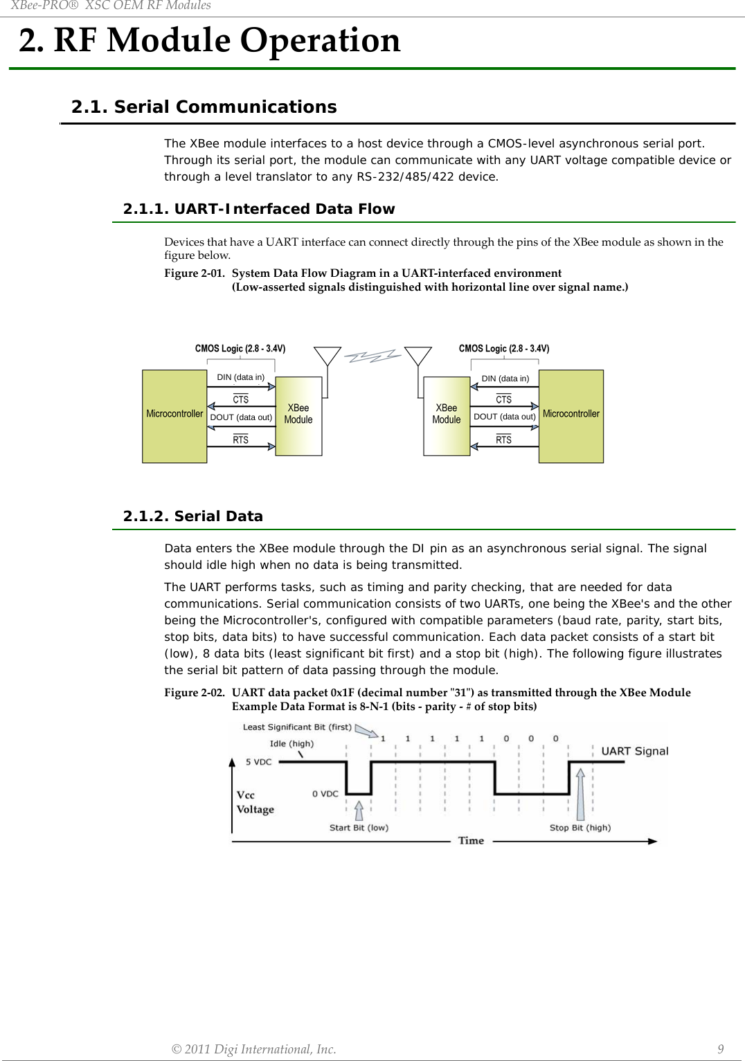
![XBee‐PRO®XSCOEMRFModules©2011DigiInternational,Inc. 102.1.3. Flow ControlFigure2‐03. InternalDataFlowDiagram(Thefivemostcommonly‐usedpinsignalsshown.)DI (Data In) Buffer and Flow ControlWhen serial data enters the XBee module through the DI Pin, then the data is stored in the DI Buffer until it can be transmitted.When the RO parameter threshold is satisfied (refer to Transmit Mode and Command Descriptions sections for more information), the module attempts to initialize an RF connection. If the module is already receiving RF data, the serial data is stored in the module's DI Buffer. If the DI buffer becomes full, hardware or software flow control must be implemented in order to prevent overflow (loss of data between the host and XBee OEM RF Module).How to eliminate the need for flow control:• Send messages that are smaller than the DI buffer size, which is generally around 1,000 bytes. • Interface at a lower baud rate (BD parameter) than the fixed RF data rate with the Retries functionality (RR parameter) disabled.Two cases in which the DI Buffer may become full and possibly overflow:• If the serial interface data rate is set higher than the RF data rate of the module, the module will receive data from the host faster than it can transmit the data over-the-air.• If the module is receiving a continuous stream of data, monitoring data on a network, or awaiting acknowledgments for Retries functionality, any serial data that arrives on the DI pin is placed in the DI Buffer. The data in the DI buffer will be transmitted over-the-air when the module no longer detects RF data in the network.Hardware Flow Control (CTS). When the DI buffer is 65 bytes away from being full; by default, the module de-asserts (high) CTS to signal to the host device to stop sending data [refer to FT (Flow Control Threshold) and CS (DO2 Configuration) Commands]. CTS is re-asserted after the DI Buffer has 34 bytes of memory available.Software Flow Control (XON). XON/XOFF software flow control can be enabled using the FL (Software Flow Control) command.DO (Data Out) Buffer and Flow ControlWhen RF data is received, the data enters the DO buffer and is then sent out the serial port to a host device. Once the DO Buffer reaches capacity, any additional incoming RF data is lost.Two cases in which the DO Buffer may become full and possibly overflow:• If the RF data rate is higher than the set interface data rate of the module, the module will receive data from the transmitting module faster than it can send the data to the host.• If the host does not allow the RF module to send data out of the DO buffer because of hard-ware or software flow control.Hardware Flow Control (RTS). If RTS is enabled for flow control (RT Parameter = 2), data will not be sent out the DO Buffer as long as RTS (pin 16) is de-asserted.Software Flow Control (XOFF). XON/XOFF software flow control can be enabled using the FL (Software Flow Control) Command. This option only works with ASCII data.](https://usermanual.wiki/Digi/XBPS3B/User-Guide-1583786-Page-10.png)
![XBee‐PRO®XSCOEMRFModules©2011DigiInternational,Inc. 112.2. Modes of OperationXBee-PRO® XSC RF Modules operate in five modes.Figure2‐04. ModesofOperation2.2.1. Idle ModeWhen not receiving or transmitting data, the RF module is in Idle Mode. The module shifts into the other modes of operation under the following conditions:• Transmit Mode (Serial data is received in the DI Buffer)• Receive Mode (Valid RF data is received through the antenna)• Sleep Mode (Sleep Mode condition is met)• Command Mode (Command Mode Sequence is issued)2.2.2. Transmit ModeWhen the first byte of serial data is received from the UART in the DI buffer, the modem attempts to shift to Transmit Mode and initiate an RF connection with other modems. After transmission is complete, the modem returns to Idle Mode.RF transmission begins after either of the following criteria is met:1. RB bytes have been received in the DI buffer and are pending for RF transmission [refer to RB (Packetization Threshold) command, p34].- The RB parameter may be set to any value between 1 and the RF packet size (PK), inclusive. When RB = 0, the packetization threshold is ignored.2. At least one character has been received in the DI buffer (pending for RF transmission) and RO time has been observed on the UART [refer to RO (Packetization Timeout) command].- The timeout can be disabled by setting RO to zero. In this case, transmission will begin after RB bytes have been received in the DI buffer.Note: RF reception must complete before the modem is able to enter into Transmit Mode.After either RB or RO conditions are met, the modem then initializes a communications channel. [Channel initialization is the process of sending an RF initializer that synchronizes receiving modems with the transmitting modem. During channel initialization, incoming serial data accumulates in the DI buffer.]Serial data in the DI buffer is grouped into RF packets [refer to PK (RF Packet Size)]; converted to RF data; then transmitted over-the-air until the DI buffer is empty. RF data, which includes the payload data, follows the RF initializer. The payload includes up to the maximum packet size (PK Command) bytes. As the transmitting modem nears the end of the transmission, it inspects the DI buffer to see if more data exists to be transmitted. This could be the case if more than PK bytes were originally pending in the DI buffer or if more bytes arrived from the UART after the transmission began. If more data is pending, the transmitting modem assembles a subsequent packet for transmission.](https://usermanual.wiki/Digi/XBPS3B/User-Guide-1583786-Page-11.png)
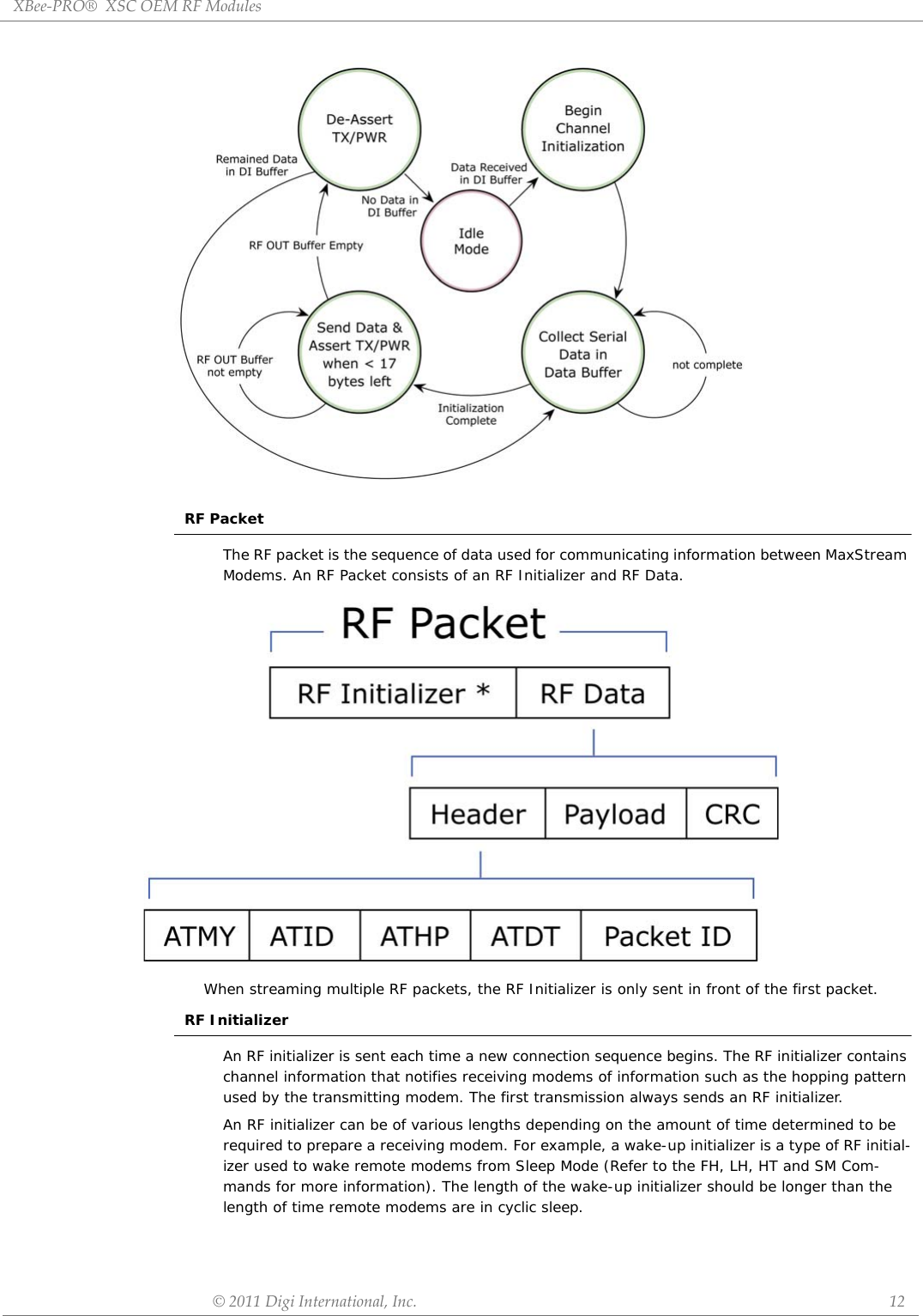
![XBee‐PRO®XSCOEMRFModules©2011DigiInternational,Inc. 13HeaderThe header contains network addressing information that filters incoming RF data. The receiv-ing modem checks for a matching Hopping Channel (HP parameter), Vendor Identification Num-ber (ID parameter) and Destination Address (DT parameter). Data that does not pass through all three network filter layers is discarded.CRC (Cyclic Redundancy Check)To verify data integrity and provide built-in error checking, a 16-bit CRC (Cyclic Redundancy Check) is computed for the transmitted data and attached to the end of each RF packet. On the receiving end, the receiving modem computes the CRC on all incoming RF data. Received data that has an invalid CRC is discarded. Receive ModeIf a module detects RF data while operating in Idle Mode, the module transitions into Receive Mode to start receiving RF packets. Figure2‐05. ReceptionofRFDataAfter a packet is received, the module checks the CRC (cyclic redundancy check) to ensure that the data was transmitted without error. If the CRC data bits on the incoming packet are invalid, the packet is discarded. If the CRC is valid, the packet proceeds to the DO Buffer.The module returns to Idle Mode after valid RF data is no longer detected or after an error is detected in the received RF data. If serial data is stored in the DI buffer while the module is in Receive Mode, the serial data will be transmitted after the module is finished receiving data and returns to Idle Mode.2.2.3. Sleep ModeSleep Modes enable the XBee module to operate at minimal power consumption when not in use. The following Sleep Mode options are available: •Pin Sleep •Cyclic Sleep For the module to transition into Sleep Mode, the module must have a non-zero SM (Sleep Mode) Parameter and one of the following must occur:• The module is idle (no data transmission or reception) for a user-defined period of time [Refer to the ST (Time before Sleep) Command].• SLEEP is asserted (only for Pin Sleep option).In Sleep Mode, the module will not transmit or receive data until the module first transitions to Idle Mode. All Sleep Modes are enabled and disabled using SM Command. Transitions into and out of Sleep Modes are triggered by various events as shown in the table below.](https://usermanual.wiki/Digi/XBPS3B/User-Guide-1583786-Page-13.png)
![XBee‐PRO®XSCOEMRFModules©2011DigiInternational,Inc. 15Cyclic Scanning. Each RF transmission consists of an RF Initializer and payload. The wake-up initializer contains initialization information and all receiving modules must wake during the wake-up initializer portion of data transmission in order to be synchronized with the transmitting module and receive the data.Figure2‐06. CorrectConfiguration(LH>SM)Lengthofthewake‐upinitializerexceedsthetimeintervalofCyclicSleep.Thereceiverisguaranteedtodetectthewake‐upinitializerandreceivetheaccompanyingpayloaddata.Figure2‐07. IncorrectConfiguration(LH<SM)Lengthofwake‐upinitializerisshorterthanthetimeintervalofCyclicSleep.Thisconfigurationisvulnerabletothereceiverwakingandmissingthewake‐upinitializer(andthereforealsotheaccompanyingpayloaddata).2.2.4. Command ModeTo modify or read module parameters, the module must first enter into Command Mode, the state in which received characters on the UART are interpreted as commands. Two command types are avail-able for programming the module:• AT Commands• Binary CommandsFor modified parameter values to persist in the module registry, changes must be saved to non-vola-tile memory using WR (Write) Command. Otherwise, parameters are restored to previously saved val-ues after the module is powered off and then on again.AT CommandsTo Enter AT Command Mode:• Send the 3-character command sequence “+++” and observe guard times before and after the command characters. [refer to ‘Default AT Command Mode Sequence’ below.] The ‘Termi-nal’ tab (or other serial communications software) of the X-CTU Software can be used to enter the sequence.[OR]• Assert (low) the CONFIG pin and either turn the power going to the module off and back on. (If using a Digi XBIB-R Interface Board, the same result can be achieved by holding the Data-In line low (also known as a break) while rebooting the module by pressing the reset button on the module assembly [module assembly = module mounted to an interface board]).](https://usermanual.wiki/Digi/XBPS3B/User-Guide-1583786-Page-15.png)
![XBee‐PRO®XSCOEMRFModules©2011DigiInternational,Inc. 16Default AT Command Mode Sequence (for transition to Command Mode):• No characters sent for one second [refer to the BT (Guard Time Before) Command]• Input three plus characters (“+++”) within one second[refer to the CC (Command Sequence Character) Command.]• No characters sent for one second [refer to the AT (Guard Time After) Command.]To Send AT Commands:Send AT commands and parameters using the syntax shown below.Figure2‐8.SyntaxforsendingATCommandsTo read a parameter value stored in the module register, leave the parameter field blank.The preceding example would change the module’s Destination Address to “0x1F”. To store the new value to non-volatile (long term) memory, the Write (ATWR) command must subsequently be sent before powering off the module.System Response. When a command is sent to the module, the module will parse and execute the command. Upon successful execution of a command, the module returns an “OK” message. If execution of a command results in an error, the module returns an “ERROR” message.To Exit AT Command Mode:• If no valid AT Commands are received within the time specified by CT (Command Mode Time-out) Command, the module automatically returns to Idle Mode. [OR]• Send ATCN (Exit Command Mode) Command.For an example of programming the RF module using AT Commands and descriptions of each config-urable parameter, refer to the “RF Module Configuration” chapter.Binary CommandsSending and receiving parameter values using binary commands is the fastest way to change operating parameters of the module. Binary commands are used most often to sample signal strength (RS parameter) and/or error counts; or to change module addresses and channels for polling systems when a quick response is necessary. Since the sending and receiving of parameter values takes place through the same data path as 'live' data (received RF payload), follow the CTS pin as outlined in Figure 2-012 to distinguish between the two types of data (commands vs 'live' data).Common questions regarding the use of binary commands: • What are the implications of asserting CMD while live data is being sent or received? • After sending serial data, is there a minimum time delay before CMD can be asserted? • Is a time delay required after CMD is de-asserted before payload data can be sent? • How to discern between live data and data received in response to a command?CMD (pin 16) must be asserted in order to send binary commands to the module. The CMD pin can be asserted to recognize binary commands anytime during the transmission or reception of data. The status of the CMD signal is only checked at the end of the stop bit as the byte is shifted into the serial port. The application does not allow control over when data is received, except by waiting for dead time between bursts of communication.If the command is sent in the middle of a stream of payload data to be transmitted, the command will essentially be executed in the order it is received. If the radio is continuously receiving data, the radio will wait for a break in the received data before executing the command. The CTS signal will frame the response coming from the binary command request [Figure 2-09].](https://usermanual.wiki/Digi/XBPS3B/User-Guide-1583786-Page-16.png)
![XBee‐PRO®XSCOEMRFModules©2011DigiInternational,Inc. 17A minimum time delay of 100 µs (after the stop bit of the command byte has been sent) must be observed before pin 5 can be de-asserted. The command executes after all parameters associated with the command have been sent. If all parameters are not received within 0.5 seconds, the module aborts the command and returns to Idle Mode.Note: Binary commands that return only one parameter byte must also be written with two parameter bytes, 0-padded, LSB first. Refer to “Programming Examples” section [pXX] for a binary programming example.Commands can be queried for their current value by sending the command logically ORed (bit-wise) with the value 0x80 (hexadecimal) with CMD asserted. When the binary value is sent (with no parameters), the current value of the command parameter is sent back through the DO pin.Figure2‐09. BinaryCommandWritethenReadSignal#4isCMD(pin16)Signal#1istheDIN(pin3)signaltotheradioSignal#2istheDOUT(pin2)signalfromtheradioSignal#3isCTS(pin12)In this graph, a value was written to a register and then read out to verify it. While not in the middle of other received data, note that the CTS signal outlines the data response out of the module.IMPORTANT: For the XBee module to recognize a binary command, the RT (DI2 Configuration) param-eter must be set to one. If binary programming is not enabled RT = 0 or 2, the module will not recog-nize that the CMD pin is asserted and therefore will not recognize the data as binary commands.](https://usermanual.wiki/Digi/XBPS3B/User-Guide-1583786-Page-17.png)
![XBee‐PRO®XSCOEMRFModules©2011DigiInternational,Inc. 193.2. Command Reference TableTable3‐01. ATCommands(TheRFModuleexpectsnumericalvaluesinhexadecimal.ʺdʺdenotesdecimalequivalent.)AT Command BinaryCommand AT Command Name Range Command Category # Bytes Returned FactoryDefault*AM 0x3A (58d) Auto-set MY - Networking & Security - -AT 0x05 (5d) Guard Time After 0x02 – 0xFFFF [x 100 msec] Command Mode Options 2 0x0A (10d)BD 0x15 (21d) Interface Data RateStandard baud rates: 0 – 6Non-standard baud rates:0x7D – 0xFFFFSerial Interfacing 2 0x03 9600bpsBT 0x04 (4d) Guard Time Before 2 – 0xFFFF [x 100 msec] Command Mode Options 2 0x0A (10d)CC 0x13 (19d) Command Sequence Character 0x20 – 0x7F Command Mode Options 1 0x2B (“+”)CD 0x28 (40d) DO3 Configuration 0 - 4 Serial Interfacing 1 0CN 0x09 (9d) Exit AT Command Mode - Command Mode Options - -CS 0x1F (31d) DO2 Configuration 0 – 4 Serial Interfacing 1 0CT 0x06 (6d) Command Mode Timeout 0x02 – 0xFFFF [x 100 msec] Command Mode Options 2 0xC8 (200d)DB RSSI level in dBm of the most recent packet 0 - 0x70 [read-only] Diagnostics 1DT 0x00 (0d) Destination Address 0 – 0xFFFF Networking 2 0E0 0x0A (10d) Echo Off - Command Mode Options - -E1 0x0B (11d) Echo On - Command Mode Options - -ER 0x0F (15d) Receive Error Count 0 – 0xFFFF Diagnostics 2 0FH 0x0D (13d) Force Wake-up Initializer - Sleep (Low Power) - -FL 0x07 (7d) Software Flow Control 0 – 1 Serial Interfacing 1 0FR Forces the module to Reset (Special)FT 0x24 (36d) Flow Control Threshold 0 – (DI buffer – 0x11) [bytes] Serial Interfacing 2 variesGD 0x10 (16d) Receive Good Count 0 – 0xFFFF Diagnostics 2 0HP 0x11 (17d) Hopping Channel 0 – 6 Networking 1 0HT 0x03 (3d) Time before Wake-up Initializer 0 – 0xFFFF [x 100 msec] Sleep (Low Power) 2 0xFFFFID 0x27 (39d) Module VID User set table: 0x10 - 0x7FFFRead-only: 0x8000 – 0xFFFF Networking 2 -LH 0x0C (12d) Wake-up Initializer Timer 0 – 0xFF [x 100 msec] Sleep (Low Power) 1 1*MD 0x32 (50d) RF Mode 0 – 4 Networking & Security 1 0MK 0x12 (18d) Address Mask 0 – 0xFFFF Networking 2 0xFFFF *MY 0x2A (42d) Source Address 0 – 0xFFFF Networking & Security 2 0xFFFFNB 0x23 (35d) Parity 0 – 5 Serial Interfacing 1 0PC 0x1E (30d) Power-up Mode 0 – 1 Command Mode Options 1 0*PK 0x29 (41d) RF Packet Size 0 - 0x100 [bytes] Serial Interfacing 2 0x40 (64d)*PL 0x3c (60d) RF Power Level 0-4 (Special) 1 4PW 0x1D (29d) Pin Wake-up 0 – 1 Sleep (Low Power) 1 0*RB 0x20 (32d) Packetization Threshold 0 - 0x100 [bytes] Serial Interfacing 2 0x01RE 0x0E (14d) Restore Defaults - (Special) - -RN 0x19 (25d) Delay Slots 0 – 0xFF [slots] Networking 1 0RO 0x21 (33d) Packetization Timeout 0 – 0xFFFF [x 200 µsec] Serial Interfacing 2 0RP 0x22 (34d) RSSI PWM Timer 0 - 0x7F [x 100 msec] Diagnostics 1 0RR 0x18 (24d) Retries 0 – 0xFF Networking 1 0RS 0x1C (28d) RSSI 0x06 – 0x36 [read-only] Diagnostics 1 -RT 0x16 (22d) DI2 Configuration 0 - 2 Serial Interfacing 1 0*RZ 0x2C (44d) DI Buffer Size [read-only] Diagnostics - -SB 0x36 (54d) Stop Bits 0 - 1 Serial Interfacing 1 0SH 0x25 (37d) Serial Number High 0 – 0xFFFF [read-only] Diagnostics 2 -SL 0x26 (38d) Serial Number Low 0 – 0xFFFF [read-only] Diagnostics 2 -SM 0x01 (1d) Sleep Mode 0, 1, 3 - 8 Sleep (Low Power) 1 0ST 0x02 (2d) Time before Sleep 0x10 – 0xFFFF [x 100 msec] Sleep (Low Power) 2 0x64 (100d)](https://usermanual.wiki/Digi/XBPS3B/User-Guide-1583786-Page-19.png)
![XBee‐PRO®XSCOEMRFModules©2011DigiInternational,Inc. 20NOTE:ATCommandsissuedwithoutaparametervalueareinterpretedasqueriesandwillreturnthecurrentlystoredparameter.*CommandsonlysupportedonS3Bhardware.3.3. Command Descriptions Commands in this section are listed alphabetically. Command categories are designated between the “< >” symbols that follow each command title. Modules expect numerical values in hexadecimal and those values are designated by a “0x” prefix.Modules operating within the same network should contain the same firmware platform to ensure the same AT Command parameters are supported.AM (Auto-set MY) CommandAT (Guard Time After) CommandSY 0x17 (23d) Time before Initialization 0 – 0xFF [x 100 msec] Networking 1 0 (disabled)TR 0x1B (27d) Transmit Error Count 0 – 0xFFFF Diagnostics 2 0TT 0x1A (26d) Streaming Limit 0 – 0xFFFF [0 = disabled] Networking 2 0xFFFFVR 0x14 (20d) Firmware Version 0 - 0xFFFF [read-only] Diagnostics 2 -WR 0x08 (8d) Write - (Special) - -Command Summary DescriptionAT Command: ATAM <Networking & Security> AM Command is used to automatically set the MY (Source Address) parameter from the factory-set module serial number. The address is formed with bits 29, 28 and 13-0 of the serial number (in that order).Binary Command: 0x3A (58 decimal)This command is only supported on S3B modules.Command Summary DescriptionAT Command: ATAT <Command Mode Options> AT Command is used to set the time-of-silence that follows the command sequence character (CC Command). By default, AT Command Mode will activate after one second of silence. Refer to the AT Commands section [p] to view the default AT Command Mode Sequence.Binary Command: 0x05 (5 decimal)Parameter Range:0x02 – 0xFFFF [x 100 milliseconds]Number of bytes returned: 2Default Parameter Value: 0x0A (10 decimal)Related Commands: BT (Guard Time Before), CC (Command Sequence Character)](https://usermanual.wiki/Digi/XBPS3B/User-Guide-1583786-Page-20.png)
![XBee‐PRO®XSCOEMRFModules©2011DigiInternational,Inc. 21BD (Interface Data Rate) CommandTable3‐02. ParameterSentvs.ParameterStoredBT (Guard Time Before) CommandCommand Summary DescriptionAT Command: ATBD <Serial Interfacing> BD Command allows the user to adjust the UART interface data rate and thus modify the rate at which serial data is sent to the module. The new baud rate does not take effect until the CN (Exit AT Command Mode) Command is issued. The RF data rate is not affected by the BD Command.Although most applications will only require one of the seven standard baud rates, non-standard baud rates are also supported.Note: If the serial data rate is set to exceed the fixed RF data rate of the module, flow control may need to be implemented as described in the Pin Signals and Flow Control sections of this manual.Non-standard Interface Data Rates: When parameter values outside the range of standard baud rates are sent, the closest interface data rate represented by the number is stored in the BD register. For example, a rate of 19200 bps can be set by sending the following command line “ATBD4B00”. NOTE: When using X-CTU Software, non-standard interface data rates can only be set and read using the X-CTU ‘Terminal’ tab. Non-standard rates are not accessible through the ‘Modem Configuration’ tab.When the BD command is sent with a non-standard interface data rate, the UART will adjust to accommodate the requested interface rate. In most cases, the clock resolution will cause the stored BD parameter to vary from the parameter that was sent (refer to the table below). Reading the BD command (send “ATBD” command without an associated parameter value) will return the value that was actually stored to the BD register.Binary Command: 0x15 (21 decimal)Parameter Range (Standard baud rates): 0 – 6(Non-standard baud rates): 0x7D – 0xFFFF (125d – 65535d)Parameter ValueBAUD (bps)Configuration0 12001 24002 48003 96004 192005 384006 57600Number of bytes returned: 2Default Parameter Value: Set to equal module’s factory-set RF data rate.BD Parameter Sent (HEX) Interface Data Rate (bps) BD Parameter Stored (HEX)0 1200 04 19,200 46 57600 612C 300 12BE100 57600 E883Command Summary DescriptionAT Command: ATBT <Command Mode Options> BT Command is used to set the DI pin silence time that must precede the command sequence character (CC Command) of the AT Command Mode Sequence. Refer to the AT Commands section [p] to view the default AT Command Mode Sequence.Binary Command: 0x04 (4 decimal)Parameter Range:2 – 0xFFFF [x 100 milliseconds]Default Parameter Value: 0x0A (10 decimal) Number of bytes returned: 2Related Commands: AT (Guard Time After), CC (Command Sequence Character)](https://usermanual.wiki/Digi/XBPS3B/User-Guide-1583786-Page-21.png)
![XBee‐PRO®XSCOEMRFModules©2011DigiInternational,Inc. 22CC (Command Sequence Character) CommandCD (DO3 Configuration) CommandCN (Exit AT Command Mode) CommandCS (DO2 Configuration) CommandCommand Summary DescriptionAT Command: ATCC <Command Mode Options> CC Command is used to set the ASCII character to be used between Guard Times of the AT Command Mode Sequence (BT+ CC + AT). The AT Command Mode Sequence activates AT Command Mode (from Idle Mode). Refer to the AT Commands section [p] to view the default AT Command Mode Sequence.Binary Command: 0x13 (19 decimal)Parameter Range: 0x20 – 0x7FDefault Parameter Value: 0x2B (ASCII “+” sign) Number of bytes returned: 1Related Commands: AT (Guard Time After), BT (Guard Time Before)DescriptionAT Command: ATCDBinary Command: 0x28 (40 decimal) <Command Mode Options> CD Command is used to define the behavior of the DO3/RX LED line.Parameter Range: 0 – 3Parameter Value Configuration0RX LED1Default high2Default low3 (reserved)4Assert only when packet addressed to module is sentDefault Parameter Value: 0Number of bytes returned: 1Command Summary DescriptionAT Command: ATCN <Command Mode Options> CN Command is used to explicitly exit AT Command Mode.Binary Command: 0x09 (9 decimal)Command Summary DescriptionAT Command: ATCS <Serial Interfacing> CS Command is used to select the behavior of the DO2 pin signal. This output can provide RS-232 flow control, control the TX enable signal (for RS-485 or RS-422 operations), or set the default level for the I/O line passing function. By default, DO2 provides RS-232 CTS (Clear-to-Send) flow control.Binary Command: 0x1F (31 decimal)Parameter Range:0 – 4Parameter Value Configuration0RS-232 flow control1 RS-485 TX enable low2high3 RS-485 TX enable high4lowDefault Parameter Value: 0Number of bytes returned: 1Minimum Firmware Version Required: 4.27D](https://usermanual.wiki/Digi/XBPS3B/User-Guide-1583786-Page-22.png)
![XBee‐PRO®XSCOEMRFModules©2011DigiInternational,Inc. 23CT (Command Mode Time out) CommandDB (RSSI in dBm) CommandDT (Destination Address) CommandE0 (Echo Off) CommandCommand Summary DescriptionAT Command: ATCT <Command Mode Options> CT Command sets the amount of time before AT Command Mode terminates automatically. After a CT time of inactivity, the module exits AT Command Mode and returns to Idle Mode. AT Command Mode can also be exited manually using CN (Exit AT Command Mode) Command.Binary Command: 0x06 (6 decimal)Parameter Range:0x02 – 0xFFFF [x 100 milliseconds]Default Parameter Value: 0xC8 (200 decimal, 20 seconds)Number of bytes returned: 2Command Summary DescriptionAT Command: ATDB <Diagnostics> DB command returns the signal level of the last packet received in dBm. This reading is useful for determining range characteristics of the Modules under various conditions of noise and distance.Once the command is issued, the module will return the value in dBm. 0x32 (50d) = -50 dBm (strong signal), and 0x64 (100d) = -100 dBm (weak signal).Binary Command: Not availableParameter Range:00x00 to 0x70 [read-only]Number of bytes returned: returned: 1Related Commands: RS (RSSI Level)Command Summary DescriptionAT Command: ATDT <Networking> DT Command is used to set the networking address of a Module. Modules use three network layers –Vendor Identification Number (ATID), Channels (ATHP), and Destination Addresses (ATDT). DT Command assigns an address to a module that enables it to communicate only with other modules having the same addresses. All modules that share the same Destination Address can communicate freely with each other. Modules in the same network with a different Destination Address (than that of the transmitter) will listen to all transmissions to stay synchronized, but will not send any of the data out their serial ports.Binary Command: 0x00Parameter Range:0 – 0xFFFFDefault Parameter Value: 0 Number of bytes returned: 2Related Commands: HP (Hopping Channel), ID (Module VID), MK (Address Mask) Command Summary DescriptionAT Command: ATE0 <Command Mode Options> E0 Command turns off character echo in AT Command Mode. By default, echo is off.Binary Command: 0x0A (10 decimal)](https://usermanual.wiki/Digi/XBPS3B/User-Guide-1583786-Page-23.png)
![XBee‐PRO®XSCOEMRFModules©2011DigiInternational,Inc. 26HT (Time before Wake-up Initializer) CommandID (Modem VID) CommandCommand Summary DescriptionAT Command: ATHT <Sleep (Low Power)> If any modules within range are running in a “Cyclic Sleep” setting, a wake-up initializer must be used by the transmitting module for sleeping modules to remain awake [refer to the LH (“Wake-up InitializerTimer”) Command]. When a receiving module in Cyclic Sleep wakes, it must detect the wake-up initializer in order to remain awake andreceive data. The value of HT Parameter tells the transmitter, “After a period of inactivity (no transmitting or receiving) lasting HT amount of time, send a long wake-up initializer”. HT Parameter should be set to match the inactivity time out [specified by ST (Time before Sleep) Command]used by the receiver(s). From the receiving module perspective, after HT time elapses and the inactivitytime out [ST Command] is met, the receiver goes into cyclic sleep. In cyclic sleep, the receiver wakes once per sleep interval to check for a wakeup initializer. When a wake-up initializer is detected, the module will stay awake to receive data. The wake-up initializer must be longer than thecyclic sleep interval to ensure that sleeping modules detect incoming data. When HT time elapses, the transmitter then knows that it needs to send a long Wake-up Initializer for all receivers to be able to remain awake andreceive the next transmission. Matching HT to the time specified by ST on the receiving module guarantees that all receivers will detect the next transmission.Binary Command: 0x03 (3 decimal)Parameter Range:0 – 0xFFFF [x 100 milliseconds]Default Parameter Value: 0xFFFF (means that long wake-up initializer will not be sent)Number of bytes returned: 2Related Commands: LH (Wake-up Initializer Timer), SM (Sleep Mode), ST (Time before Sleep)Command Summary DescriptionAT Command: ATID <Networking> Set/Read the “Vendor Identification Number”. Only modemswith matching IDs can communicate with each other. Modules with non-matchingVIDs will not receive unintended data transmission.Binary Command: 0x27 (39 decimal)Parameter Range (user-set table) 0x10 - 0x7FFFF (Factory-set and read-only) 0x8000 – 0xFFFFNumber of bytes returned: 2](https://usermanual.wiki/Digi/XBPS3B/User-Guide-1583786-Page-26.png)
![XBee‐PRO®XSCOEMRFModules©2011DigiInternational,Inc. 27LH (Wake-up Initializer Timer) CommandMD (RF Mode) Command Command Summary DescriptionAT Command: ATLH <Sleep (Low Power)> LH Command adjusts the duration of time for which the RF initializer is sent.When receiving modules are put into Cyclic Sleep Mode, they power-down after a period of inactivity [specified by ST (Time before Sleep) Command] and will periodically awaken and listenfor transmitted data. In order for the receiving modules to remain awake, they must detect~35ms of the wake-up initializer. LH Command must be used whenever a receiver is operating in Cyclic Sleep Mode. This lengthensthe Wake-up Initializer to a specific amount of time (in tenths of a second). The Wake-up Initializer Time must be longer than the cyclic sleep time that is determined by SM (Sleep Mode)Command. If the wake-up initializer time were less than the Cyclic Sleep interval, the connection would be at risk of missing the wake-up initializer transmission. Refer to Figures 3.1 & 3.2 of the SM Command description to view diagrams of correct and incorrect configurations. The images help visualize the importance that the value of LH be greater than the value of SM.Binary Command: 0x0C (12 decimal)Parameter Range:0 – 0xFF [x 100 milliseconds]Default Parameter Value: 1Number of bytes returned: 1Related Commands: HT (Time before Wake-up Initializer), SM (Sleep Mode), ST (Time before Sleep)Command Summary DescriptionAT Command: ATMD <Networking & Security> The MD command is used to select/read the RF Mode (Peer-to-peer, Multi-Stream or Repeater Modes) of the module.Multi-Streaming Mode enables exclusive connections in point-to-multipoint networks. Refer to the Multi-Streaming Mode section [p43] for more information regarding how these parameter values affect other parameter values.Repeater Mode enables longer range via an intermediary module. When MD=3, the module will act as a “store and forward” repeater. Any packets not addressed to this node will be repeated. A Repeater End Node (MD=4) handles repeated messages, but will not forward the data over-the-air. Refer to the Repeater Mode section [p38] for more information.Binary Command: 0x32 (50 decimal)Parameter Range: 0 – 4Default Parameter Value: 0Number of bytes returned: 1Related Commands: CB (Connection Duration Time out), CE (Connection Inactivity Time out), CM (Connection Message), DC (Disconnect)This command is only supported on S3B modules.Parameter Configuration0Peer-to-Peer(transparent operation)1Multi-Steam Base2Multi-Steam Remote3Repeater & End Node4End Node](https://usermanual.wiki/Digi/XBPS3B/User-Guide-1583786-Page-27.png)
![XBee‐PRO®XSCOEMRFModules©2011DigiInternational,Inc. 28MK (Address Mask) CommandMY (Source Address) CommandNB (Parity) CommandCommand Summary DescriptionAT Command: ATMK <Networking> MK Command is used to set/read the Address Mask.All data packets contain the Destination Address of the transmitting module.When an RF data packet is received, the transmitter’s Destination Address is logically “ANDed” (bitwise) with the Address Mask of the receiver. The resulting value must match the Destination Address or theAddress Mask of the receiver for the packet to be received and sent out themodule’s DO serial port. If the “ANDed” value does not match either theDestination Address or the Address Mask of the receiver, the packet is discarded. (All “0” values are treated as “irrelevant” values and are ignored.)Binary Command: 0x12 (18 decimal)Parameter Range:0 – 0xFFFFDefault Parameter Value: 0xFFFF (Destination address (DT parameter) of the transmitting module must exactly match the destination address of the receiving module.)Number of bytes returned: 2Related Commands: DT (Destination Address), HP (Hopping Channel), ID (Module VID)Command Summary DescriptionAT Command: ATMY <Networking & Security> Set/Read the source address of the module.Refer to the Addressing section [p36] of the RF Communication Modes chapter for more information.Binary Command: 0x2A (42 decimal)Parameter Range: 0 – 0xFFFFDefault Parameter Value: 0xFFFF (Disabled – the DT (Destination Address) parameter serves as both source and destination address.)Number of bytes returned: 2Related Commands: DT (Destination Address), HP (Hopping Channel), ID (Modem VID), MK (Address Mask), AM (Auto-set MY)This command is only supported on S3B modules.Command Summary DescriptionAT Command: ATNB <Serial Interfacing> Select/Read parity settings for UART communications.Binary Command: 0x23 (35 decimal)Parameter Range:0 – 4 (S3 Hardware)0-5 (S3B Hardware)Parameter Value Configuration08-bit (no parity or 7-bit (any parity)18-bit even28-bit odd38-bit mark48-bit space5 9-bit data (S3B Hardware)Default Parameter Value: 0Number of bytes returned: 1](https://usermanual.wiki/Digi/XBPS3B/User-Guide-1583786-Page-28.png)
![XBee‐PRO®XSCOEMRFModules©2011DigiInternational,Inc. 29PC (Power-up to AT Mode) CommandPK (RF Packet Size) CommandPL (Module Power Level) CommandCommand Summary DescriptionAT Command: ATPC <Command Mode Options> PC Command allows the module to power-updirectly into AT Command Mode from reset or power-on. If PC Command isenabled with SM Parameter set to 1, DI3 (pin 9) can be used to enter themodule into AT Command Mode. When the DI3 pin is de-asserted (low),the module will wake-up in AT Command Mode. This behavior allows moduleDTR emulation.Binary Command: 0x1E (30 decimal)Parameter Range:0 – 1Parameter Value Configuration0 Power-up to Idle Mode1Power-up toAT Command ModeDefault Parameter Value: 0Number of bytes returned: 1Command Summary DescriptionAT Command: ATPK <Serial Interfacing> Set/Read the maximum size of the RF packets sent out a transmitting module. The maximum packet size can be used along with the RB and RO parameters to implicitly set the channel dwell time.Changes to this parameter may have a secondary effect on the RB (Packet Control Characters) parameter. RB must always be less than or equal to PK. If PK is changed to a value less than the current value of RB, RB is automatically lowered to be equal to PK.Binary Command: 0x29 (41 decimal) Parameter Range: 0 – 0x100 [Bytes]Default Parameter Value: 0x40 (64 decimal)Number of bytes returned: 2Related Commands: RB (Packetization Threshold), RO (Packetization Time out)This command is only supported on S3B modules.Command Summary DescriptionAT Command: ATPL <Special Commands> Set/Read the power level at which the RF module transmits conducted power. This command is only supported on S3B hardware. Power level 4 is calibrated and the other power levels are approximate.Binary Command: 0x3C (60 decimal)Parameter Range:0 – 4Parameter Value Configuration0 +7.0 dBm1 +15.0dBm2 +18.0dBm3 +21.0dBm4 +24.0 dBmDefault Parameter Value: 4Number of bytes returned: 1This command is only supported on S3B hardware](https://usermanual.wiki/Digi/XBPS3B/User-Guide-1583786-Page-29.png)
)Default Parameter Value: 1Number of bytes returned: 2Related Commands: PK (RF Packet Size), RO (Packetization Time out)This command is only supported on S3B modules.Command Summary DescriptionAT Command: ATRE <Diagnostics> RE Command restores all configurable parameters to factorydefault settings. However, RE Command will not write the default values tonon-volatile (persistent) memory. Unless the WR (Write) Command isissued after the RE command, the default settings will not be saved in theevent of module reset or power-down.Binary Command: 0x0E (14 decimal)](https://usermanual.wiki/Digi/XBPS3B/User-Guide-1583786-Page-30.png)
![XBee‐PRO®XSCOEMRFModules©2011DigiInternational,Inc. 31RN (Delay Slots) CommandRO (Packetization Time out) CommandRP (RSSI PWM Timer) CommandCommand Summary DescriptionAT Command: ATRN <Networking> RN Command is only applicable if retries have beenenabled [RR (Retries) Command], or if forced delays will be inserted intoa transmission [refer to TT (Streaming Limit) Command]. RN Command isused to adjust the time delay that the transmitter inserts before attemptingto resend a packet. If the transmitter fails to receive an acknowledgementafter sending a packet, it will insert a random number of delay slots(ranging from 0 to (RN minus 1)) before attempting to resend the packet.Each delay slot lasts for a period of 38ms.If two modules attempted to transmit at the same time, the random timedelay after packet failure would allow one of the two modules to transmitthe packet successfully, while the other would wait until the channelopens up to begin transmission.Binary Command: 0x19 (25 decimal)Parameter Range:0 – 0xFF [slots]Default Parameter Value: 0 (no delay slots inserted) Number of bytes returned: 1Command Summary DescriptionAT Command: ATRO <Serial Interfacing> RO Command is used to specify/read the time ofsilence (no bytes received) after which transmission begins. After a serialbyte is received and if no other byte is received before the RO time out,the transmission will start.Binary Command: 0x21 (33 decimal)Parameter Range:0 – 0xFFFF [x 200 µs]Default Parameter Value: 0 Number of bytes returned: 2Command Summary DescriptionAT Command: ATRP <Diagnostics> RP Command is used to enable a PWM (“Pulse Width Modulation”)output on the Config pin which is calibrated to show the level thereceived RF signal is above the sensitivity level of the module. The PWMpulses vary from zero to 95 percent. Zero percent means the received RFsignal is at or below the published sensitivity level of the module. The followingtable shows levels above sensitivity and PWM values.The total period of the PWM output is 8.32 ms. There are 40 steps in thePWM output and therefore the minimum step size is 0.208 ms.Binary Command: 0x22 (34 decimal)Parameter Range:0 - 0x7F[x 100 milliseconds]Default Parameter Value: 0 (disabled) Number of bytes returned: 1](https://usermanual.wiki/Digi/XBPS3B/User-Guide-1583786-Page-31.png)
![XBee‐PRO®XSCOEMRFModules©2011DigiInternational,Inc. 33RS (RSSI) CommandRT (DI2 Configuration) CommandSB (Stop Bits) CommandSH (Serial Number High) CommandCommand Summary DescriptionAT Command: ATRS <Diagnostics> RS Command returns the signal level of the last packetreceived. This reading is useful for determining range characteristics of themodules under various conditions of noise and distance.Once the command is issued, the module will return a value between 0x6and 0x36 where 0x36 represents a very strong signal level and 0x4 indicatesa low signal level.Binary Command: 0x1C (28 decimal)Parameter Range: 0x06 – 0x36 [read-only]Number of bytes returned: 1Command Summary DescriptionAT Command: ATRT <Serial Interfacing> RT command is used to dictate the behavior of theDI2/RTS/CMD line. RT Command must be issued to enable RTS flow controlor binary programming.Binary Command: 0x16 (22 decimal)Parameter Range:0 – 2Parameter Value Configuration0 disabled1 Enable Binary Programming2Enable Flow ControlDefault Parameter Value: 0Number of bytes returned: 1Command Summary DescriptionAT Command: ATSB SB Command is used to set/read the number of stop bits in the data packets.Binary Command: 0x36 (54 decimal)Parameter Range:0 – 1Parameter Value Configuration01 stop bits12 stop bitsDefault Parameter Value: 0Number of bytes returned: 1Command Summary DescriptionAT Command: ATSH <Diagnostics> Read the serial number high word of the module.Binary Command: 0x25 (37 decimal)Parameter Range:0 – 0xFFFF [read-only]Number of bytes returned: 2Related Commands: SL (Serial Number Low)](https://usermanual.wiki/Digi/XBPS3B/User-Guide-1583786-Page-33.png)
![XBee‐PRO®XSCOEMRFModules©2011DigiInternational,Inc. 34SL (Serial Number Low) CommandSM (Sleep Mode) CommandST (Time before Sleep) CommandCommand Summary DescriptionAT Command: ATSL <Diagnostics> Read the serial number low word of the module.Binary Command: 0x26 (38 decimal)Parameter Range:0 – 0xFFFF [read-only]Number of bytes returned: 2Related Commands: SH (Serial Number High)Command Summary DescriptionAT Command: ATSM <Sleep Mode (Low Power)> SM Command is used to adjust Sleep Mode settings. By default, Sleep Mode is disabled and the module remains continually active. SM Command allows the module to run in a lower-powerstate and be configured in one of eight settings. Cyclic Sleep settings wake the module after the amount of time designatedby SM Command. If the module detects a wake-up initializer during the time it is awake, it will synchronize with the transmitter and start receiving data after the wake-up initializer runs its duration. Otherwise, itreturns to Sleep Mode and continue to cycle in and out of inactivity until the Wake-up Initializer is detected. If a Cyclic Sleep setting is chosen, the ST, LH and HT parameters must also be set as described in the “SleepMode” section of this manual.Binary Command: 0x01Parameter Range:0,1 3-8Parameter Value Configuration0 Disabled1Pin Sleep3Cyclic 0.5 second sleep (Module wakes every 0.5 seconds)4 Cyclic 1.0 second sleep5 Cyclic 2.0 second sleep6 Cyclic 4.0 second sleep7 Cyclic 8.0 second sleep8 Cyclic 16.0 second sleepDefault Parameter Value: 0Number of bytes returned: 1Related Commands: For Pin Sleep – PC (Power-up Mode), PW (Pin Wake-up) For Serial Port Sleep – ST (Time before Sleep)For Cyclic Sleep – ST (Time before Sleep), LH (Wake-up Initializer Timer), HT (Time Before Wake-up Initializer), PW (Pin Wake-up)Command Summary DescriptionAT Command: ATST <Sleep Mode (Low Power)> ST Command sets the period of time (intenths of seconds) in which the module remains inactive before enteringinto Sleep Mode. For example, if the ST Parameter is set to 0x64 (100decimal), the module will enter into Sleep mode after 10 seconds of inactivity(no transmitting or receiving). This command can only be used ifCyclic Sleep or Serial Port Sleep Mode settings have been selected usingSM (Sleep Mode) Command.Binary Command: 0x02Parameter Range:0x10 – 0xFFFF [x 100 milliseconds]Default Parameter Value: 0x64 (100 decimal)Number of bytes returned: 2Related Commands: SM (Sleep Mode), LH (Wake-up Initializer Timer), HT (Time before Wake-up Initializer)](https://usermanual.wiki/Digi/XBPS3B/User-Guide-1583786-Page-34.png)
![XBee‐PRO®XSCOEMRFModules©2011DigiInternational,Inc. 35SY (Time before Initialization) CommandTR (Transmit Error Count) CommandCommand Summary DescriptionAT Command: ATSY <Networking> SY Command keeps a communication channel open as long as module transmits or receives before the active connection expires. It can be used to reduce latency in a query/response sequence and should be set 100 ms longer than the delay between transmissions. This command allows multiple Modules to share a hopping channelfor a given amount of time after receiving data. By default, all packets include an RF initializer that contains channel information used to synchronize any listening receivers to the transmitter’s hopping pattern. Once a new module comes within range, it is able to instantly synchronize to thetransmitter and start receiving data. If no new modules are introduced into the system, the synchronization information becomes redundant once moduleshave become synchronized.SY Command allows the modules to remove this information from the RF Initializer after the initial synchronization. For example, changing the SY Parameter to 0x14 (20 decimal) allows all modules to remain in sync for 2seconds after the last data packet was received. Synchronization information is not re-sent unless transmission stops for more than 2 seconds. This command allows significant savings in packet transmission time.Warning: Not recommended for use in an interference-prone environment. Interference can break up the session and the communications channel will not be available again until SY time expires. With SY set to zero, the channel session is opened and closed with each transmission - resulting in a more robust link with more latency.Binary Command: 0x17 (23 decimal)Parameter Range:0 – 0xFF[x 100 milliseconds]Default Parameter Value: 0 (Disabled - channel initialization information is sent with each RF packet.)Number of bytes returned: 1Command Summary DescriptionAT Command: ATTR <Diagnostics> TR Command records the number of retransmit failures.This number is incremented each time a packet is not acknowledged withinthe number of retransmits specified by the RR (Retries) Command. Ittherefore counts the number of packets that were not successfully receivedand have been dropped.The TR Parameter is not non-volatile and will therefore be reset to zeroeach time the module is reset.Binary Command: 0x1B (27 decimal)Parameter Range:0 – 0xFFFFDefault Parameter Value: 0 Number of bytes returned: 2Related Commands: RR (Retries)](https://usermanual.wiki/Digi/XBPS3B/User-Guide-1583786-Page-35.png)
![XBee‐PRO®XSCOEMRFModules©2011DigiInternational,Inc. 37AppendixA:AgencyCertificationsFCC (United States) CertificationThe XBee-PRO® XSC OEM RF Module complies with Part 15 of the FCC rules and regulations. Compliance with the labeling requirements, FCC notices and antenna usage guidelines is required.In order to operate under Digi’s FCC Certification, OEMs/integrators must comply with the following regulations:Labeling RequirementsWARNING: The Original Equipment Manufacturer (OEM) must ensure that FCC labeling requirements are met. This includes a clearly visible label on the outside of the final product enclosure that displays the text shown in the figure below.FigureA‐01. RequiredFCCLabelforOEMproductscontainingtheXBee‐PRO®XSCOEMRFModule.XBEE PRO S3ORXBEE PRO S3BFCC NoticesIMPORTANT: The XBee-PRO® XSC OEM RF Module has been certified by the FCC for use with other products without any further certification (as per FCC section 2.1091). Modifications not expressly approved by Digi could void the user's authority to operate the equipment.IMPORTANT: OEMs must test final product to comply with unintentional radiators (FCC section 15.107 & 15.109) before declaring compliance of their final product to Part 15 of the FCC Rules.IMPORTANT: The RF module has been certified for remote and base radio applications. If the module will be used for portable applications, the device must undergo SAR testing.This equipment has been tested and found to comply with the limits for a Class B digital device, pursuant to Part 15 of the FCC Rules. These limits are designed to provide reasonable protection against harmful interference in a residential installation. This equipment generates, uses and can radiate radio frequency energy and, if not installed and used in accordance with the instructions, may cause harmful interference to radio communications. However, there is no guarantee that interference will not occur in a particular installation. If this equipment does cause harmful interference to radio or television reception, which can be determined by turning the equipment off and on, the user is encouraged to try to correct the 1. The system integrator must ensure that the text provided with this device [Figure A-01] is placed on the outside of the final product and within the final product operation manual.2. The XBee-PRO® XSC OEM RF Module may only be used with antennas that have been tested and approved for use with this module Refer to to Table A-1.Contains FCC ID: MCQ-XBEEXSCThe enclosed device complies with Part 15 of the FCC Rules. Operation is subject to the following two conditions: (i.) this device may not cause harmful interference and (ii.) this device must accept any inter-ference received, including interference that may cause undesired operation.Contains FCC ID: MCQ-XBPS3BThe enclosed device complies with Part 15 of the FCC Rules. Operation is subject to the following two conditions: (i.) this device may not cause harmful interference and (ii.) this device must accept any inter-ference received, including interference that may cause undesired operation.](https://usermanual.wiki/Digi/XBPS3B/User-Guide-1583786-Page-37.png)