Digi XBPS3B XBEE PRO XSC User Manual manual xs oem rf module v42b5
Digi International Inc XBEE PRO XSC manual xs oem rf module v42b5
Digi >
Manual
11001 Bren Road East
Minnetonka, MN 55343
www.digi.com
XBee-PRO® XSC RF Module
XBee-PRO® XSC RF Module
RF Module Operation
RF Module Configuration
Appendices
Product Manual
For RF Module Part Number:
XBP09-XC…
900 MHz OEM RF Modules by Digi International Inc.
90000938_C
11, 3, 2011

XBee‐PRO®XSCRFModule‐ProductManual
©2011DigiInternational,Inc. ii
© 2011 Digi International, Inc. All rights reserved
Nopartofthecontentsofthismanualmaybetransmittedorreproducedinany
formorbyanymeanswithoutthewrittenpermissionofDigiInternational,Inc.
XBee‐PRO®isaregisteredtrademarkofDigiInternationalInc.
TechnicalSupport:Phone:(801)765‐9885
LiveChat:www.digi.com

Contents
XBee‐PRO®XSCOEMRFModules
©2011DigiInternaitonal,Inc. 1
1. XBee-PRO® XSC OEM RF Module 4
Key Features 4
Worldwide Acceptance 4
Specifications 5
Pin Signals 6
Electrical Characteristics 7
Timing Specifications 7
Mechanical Drawings 8
2. RF Module Operation 9
Serial Communications 9
UART-Interfaced Data Flow 9
Serial Data 9
Flow Control 10
Modes of Operation 11
Idle Mode 11
Transmit Mode 11
Sleep Mode 13
Command Mode 15
3. RF Module Configuration 18
XBee Programming Examples 18
AT Commands 18
Binary Commands 18
Command Reference Table 19
Command Descriptions 20
Agency Certifications 37
FCC (United States) Certification 37
Labeling Requirements 37
FCC Notices 37
Limited Modular Approval 38
FCC-approved Antennas 38
IC (Industry Canada) Certification 38
Additional Information 42
1-Year Warranty 42
Contact Digi 42

XBee‐PRO®XSCOEMRFModules
©2011DigiInternational,Inc. 4
1.XBee‐PRO®XSCOEMRFModule
The XBee-PRO XSC (900 MHz) OEM RF Modules were
engineered to afford OEMs and integrators an easy-to-use RF
solution that provides reliable delivery of critical data between
remote devices. These modules come configured to sustain
reliable long-range wireless links.
The XBee Module is a drop-in wireless solution that transfers a
standard asynchronous serial data stream.
1.1. Key Features
1.1.1. Worldwide Acceptance
FCC Certified (USA) - Refer to Appendix A for FCC Requirements.
Systems that include XBee-PRO Modules inherit Digi’s FCC Certification
ISM (Industrial, Scientific & Medical) frequency band
Manufactured under ISO 9001:2000 registered standards
XBee-PRO™ XSC (900 MHz) OEM RF Modules are approved for use in US and
Canada.
RoHS compliant
Long Range Data Integrity
XBee-PRO XSC- S3:
• Indoor/Urban: 1200' (370m)
• Outdoor line-of-sight: Up to 6 miles (9.6
km)
• Outdoor line-of-sight: Up to 15 miles (24
km) w/ high gain antenna
• Receiver Sensitivity: -106 dBm,
XBee-PRO XSC-S3B:
• Indoor/Urban range: 2000’ (610 m)
• Outdoor line-of-sight range: 9 miles (14 km)
• Receiver Sensitivity: -109 dBm
Advanced Networking & Security
• True peer-to-peer (no “master” required)
communications
• Point-to-point & point-to-multipoint topolo-
gies supported
• Retries and Acknowledgements
• 7 hopping channels, each with over 65,000
available network addresses
• FHSS (Frequency Hopping Spread Spec-
trum)
Easy-to-Use
• Continuous RF data stream
up to 9600 bps
• No configuration required for out-of-the-box
RF data communications
• Advanced configurations available through
standard AT & binary Commands
• Portable (small form factor easily designed
into a wide range of data radio systems)
• Software-selectable serial interface baud rates
• I/O Support: CTS, RTS (& more)
• Support for multiple data formats
(parity, start and stop bits, etc.)
• Power-saving Sleep Modes

XBee‐PRO®XSCOEMRFModules
©2011DigiInternational,Inc. 5
1.2. Specifications
Table1‐01. XBee‐PROXSCOEMRFModuleSpecifications
Specification XBee-PRO XSC (S3) (900 MHz)
OEM RF Module XBee-PRO XSC
(S3B)
Performance
Indoor/Urban Range Up to 1200ft (370m) up to 2000ft (610m)
Outdoor line-of-sight Range Up to 6 miles (9.6km) w/ dipole antenna
Up to 15 miles (24 km) w/ high-gain antenna
Up to 9 miles (14km) w/
dipole antenna
Up to 28 miles (45km) w/
high-gain antenna
Interface Data Rate 125 - 65,000 bps
(Software selectable, includes non-standard baud rates)
Throughput Data Rate 9,600 bps 9.6 kbps or 19.2kbs
RF Data Rate 10 kbps 10 kbps or 20kbs
Transmit Power Output 100 mW (+20 dBm) 24dBm @ 215mA
Receiver Sensitivity -106dBm -109dBm at 9600 baud
-107dBm at 19200 baud
Power Requirements
Supply Voltage 3.0-3.6 VDC regulated 2.4 to 3.6v
Receive Current 65mA 26mA typical
Transmit Current 265mA 215mA at 24dBm
Power Down Current 50 uA 2.5uA typical @3.3v
General
Frequency Range 902-928 MHz (located in the 900MHz ISM Band)
Spread Spectrum Frequency Hopping
Network Topology Point-to-Point, Peer-to-Peer, Point-to-Multipoint
Channel Capacity 7 hop sequences share 25 frequencies
Board-level Serial Data Interface (S3B) 3V CMOS UART (5V-tolerant) 3V CMOS UART
Physical Properties
Module Board Size 1.297" x 0.962" x 0.215 (3.29 cm x 2.44 cm x 0.546 cm)
Note: Dimensions do not include connector/antenna or pin lengths
Weight 5 to 8 grams, depending on the antenna option
Connector 2 rows of 10 pins, 22mm apart with 2mm spaced male Berg-type headers
Operating Temperature -40 to 85º C (industrial)
Antenna Options
Integrated Wire ¼ wave monopole, 3.25” (8.26 cm) length, 1.9 dBi Gain
Integrated Helical 0.315" (0.8 cm) height
RF Connector Reverse-polarity SMA or U.FL
Impedance 50 ohms unbalanced
Certifications)
FCC Part 15.247 MCQ-XBEEXSC MCQ-XBPS3B
Industry Canada (IC) 1846A-XBEEXSC 1846A-XBPS3B
Europe N/A
RoHS Compliant
Australia N/A Pending
XBee‐PRO®XSCOEMRFModules
©2011DigiInternational,Inc. 6
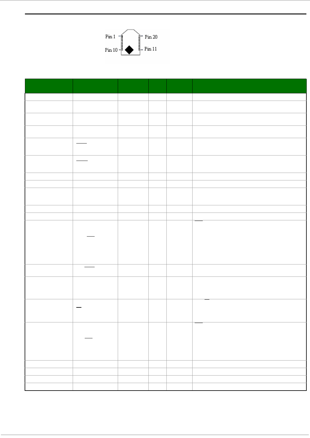
1.3. Pin Signals
Figure1‐01. XBee‐PROXSCOEMRFModulePinNumbers(topview,shieldunderneath)
Table1‐02. J1PinSignalDescriptions
(Low‐assertedsignalsdistinguishedwithahorizontallineoversignalname.)
Note:*S3hasa100kpull‐up.S3Bhasinternalpull‐up.**S3has10kpull‐up.S3Bhasinternalpull‐up.
Module Pin Public Signal Notes I/O When
Active Function
1 VCC I Supply Voltage
2 DO (Data Out) O n/a Serial data exiting the module (to the UART host). Refer to the
Serial Communications section for more information
3 DI (Data In I n/a Serial data entering the module (from UART host). Refer to the
Serial Communications section for more information.
4 DO3 / RX LED O high Pin is driven high during RF data reception; otherwise, the pin is
driven low. Refer to the CD Command section to enable.
5 Reset
**Has a pull up
resistor I/O low Re-boot module.(minimum pulse is 90us) Open Drain
configuration. Module will drive reset line low momentarily on
reboot and power up.
6 Config *Has a pull up
resistor I low / high Pin can be used as a backup method for entering Command
Mode during power-up. Primary method is with “+++”. Refer to
the AT Commands section for more information.
7 O Driven high Do not Connect
8 NC Do not Connect
9 DI3 / SLEEP *Has a pull up
resistor Ihigh By default, DI3 pin is not used. To configure this pin to support
Sleep Modes, refer to the Sleep Mode, SM Command and PW
Command sections.
10 GND Ground
11 O Driven high Do not Connect
12 DO2 / CTS / RS-485
Enable Olow
CTS(clear-to-send) flow control - When pin is driven low, UART
host is permitted to send serial data to the module. Refer to the
Serial Communications and CS Command sections for more
information.
----------------------------------------------------------------
RS-485 Enable - To configure this pin to enable RS-485 (2-wire
or 4-wire) communications, refer to the Serial Communications
and CS Command sections.
13 ON / Sleep Ohigh high = Indicates power is on and module is not in Sleep Mode.
Low = Sleep mode or module is unpowered
14 VREF I n/a
Not used on this module. For compatibility with other XBee
modules, we recommend connecting this pin to a voltage
reference if Analog sampling is desired. Otherwise, connect to
GND.
15 TX / PWR O n/a
low = TX - Pin pulses low during transmission
--------------------------------------------------------------
high = PWR - Indicates power is on and module is not in Sleep
Mode
16 DI2 / RTS / CMD *Has a pull
down resistor Ilow
RTS (request-to-send) flow control - By default, this pin is not
used. To configure this pin to regulate the flow of serial data
exiting the module, refer to the Serial Communications and RT
Command sections. -------------------
--------------------------------------------
CMD -Refer to Binary Commands and RT Command sections
to enable binary command programming.
17 O Driven low Do not Connect
18 O Driven low Do not Connect
19 O Driven low Do not Connect
20 O Driven low Do not Connect
XBee‐PRO®XSCOEMRFModules
©2011DigiInternational,Inc. 7
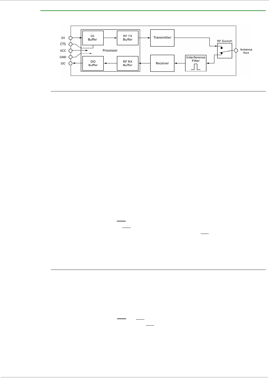
1.4. Electrical Characteristics
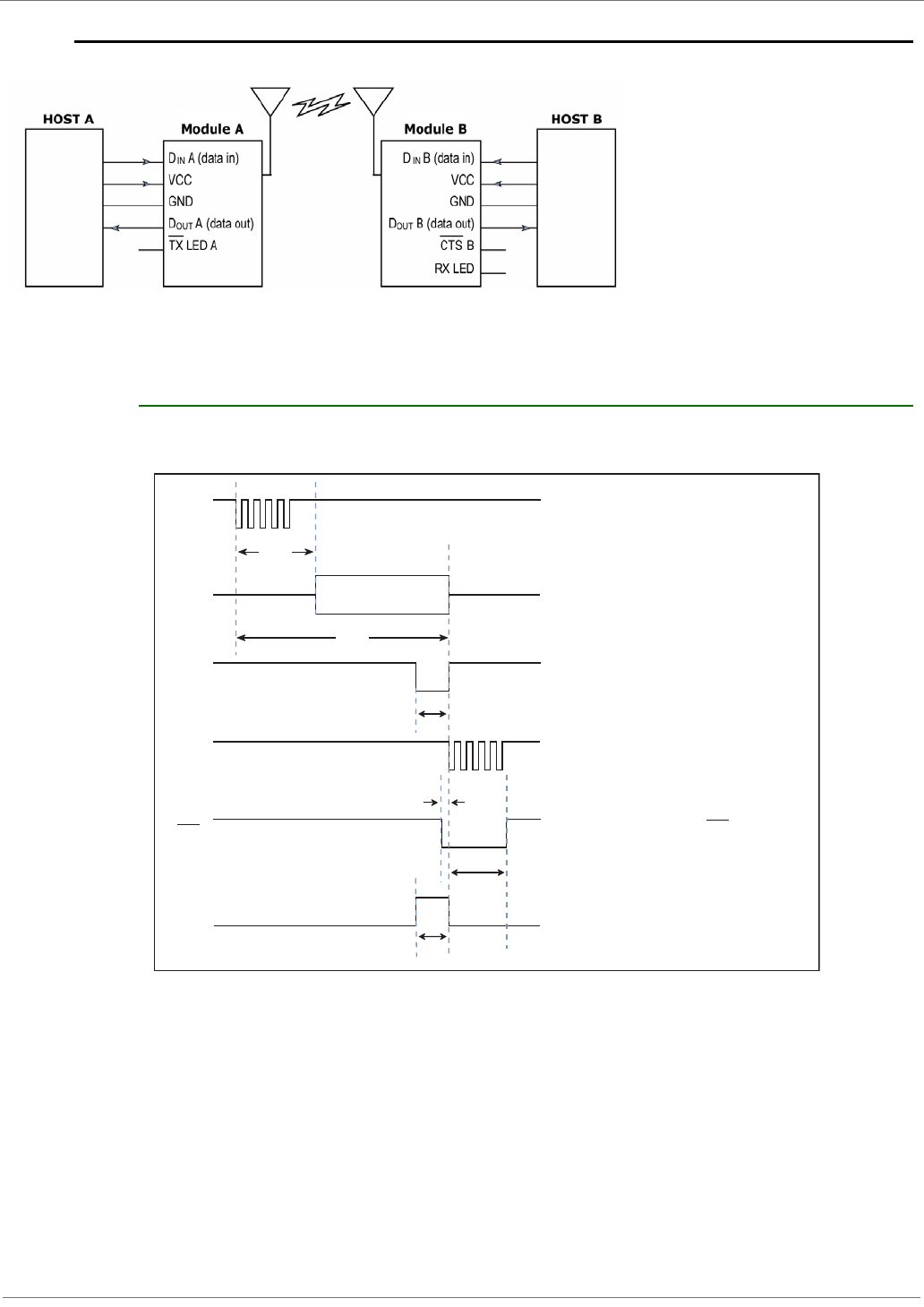
Figure1‐02. SystemBlockDiagramBasicwirelesslinkbetweenhosts
The data flow sequence is initiated when the first byte of data is received in the DI Buffer of the
transmitting module (XBee Module A). As long as XBee Module A is not already receiving RF data,
data in the DI Buffer is packetized, then transmitted over-the-air to XBee Module B.
1.4.1. Timing Specifications
Figure1‐03. TimingSpecifications(“A”and“B”refertoFigure1‐02.)
A Transmits over air
B Receives
T
ST
T
TX
T
TL
T
RL
Host A sends serial data to XBee Module A
After T , contents of D Buffer
are assembled into packet and transmitted
IN
TX/PWR LED on XBee Module A pulses off
briefly to indicate RF transmission
If 16-bit CRC checks out, data is shifted out
serial port to Host B
(Optional) Set ATCS = 1 to use CTS as RS-485
TX enable low-asserted signal
RX LED pulses on briefly to indicate RF reception
DA
IN
RF A
OUT
TX LED A
D B
OUT
RX LED B
CTS B
ST
T
CLDL
T
CHDH
XBee‐PRO®XSCOEMRFModules
©2011DigiInternational,Inc. 8
Table1‐03. ACCharacteristics(SYparameter=0,symbolscorrespondtoFigure1‐02andFigure1‐03.)
Table1‐04. DCCharacteristics(Vcc=3.0‐3.6VDC)
Note:*MinVoltageforS3Bis2.4v,howeverMaxPowerwillbereducedandSensitivitymaydegrade.
**S3istolerantupto5.5voninputpins.
***S3Bcanhavepull‐upsenabledandstillmaintainlowleakagecurrent.
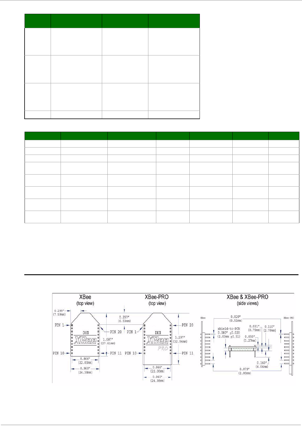
1.5. Mechanical Drawings
Figure1‐04. MechanicalDrawings
Symbol Description 9600 baud rate
(32 byte packet) 9600 timing
(B=number of bytes)
TTX Latency from the time data
is transmitted until received 72.0 ms
For 0 < B < 40,
T = 46.27 + (0.73 * B) ms
For B >= 39 bytes,
T = 74.80 ms
TTL Time that TX/PWR pin is
driven low 16.8 ms
For 0 < B < 14,
T = 6.50 + (0.8 * B) ms
For B > 13
T = 16.80 ms
TRL Time that RX LED pin is
driven high 25.6 ms
For 0 < B < 37,
T = 1.63 + (0.794 * B)
For B > 36,
T = 30.2 ms
TST Channel Initialization Time 35.0 ms 35.0 ms
Symbol Parameter Condition Min Typical Max Units
Vcc Module Supply Voltage *3.0 3.6 V
VIL Input Low Voltage All input signals -0.3 0.3Vcc V
VIH Input High voltage All input signals 0.7Vcc Vcc + 0.3 ** V
VOL Output Low-Level
Voltage Iout = Iout_Max 0.4 V
VOH Output High-Level
Voltage Iout = Iout_Max Vcc-0.4 V
IL Input Leakage Current ***With Pull-up resistors
disabled 40 400 nA
IO1 Output Current pins 2, 15 (Dout, ~TX/
Pwr) 2mA
IO2 Output Current pins 4, 12, 13
(DCD,~CTS,ON/~Sleep) 8mA
XBee‐PRO®XSCOEMRFModules
©2011DigiInternational,Inc. 9
2.RFModuleOperation
2.1. Serial Communications
The XBee module interfaces to a host device through a CMOS-level asynchronous serial port.
Through its serial port, the module can communicate with any UART voltage compatible device or
through a level translator to any RS-232/485/422 device.
2.1.1. UART-Interfaced Data Flow
DevicesthathaveaUARTinterfacecanconnectdirectlythroughthepinsoftheXBeemoduleasshowninthe
figurebelow.
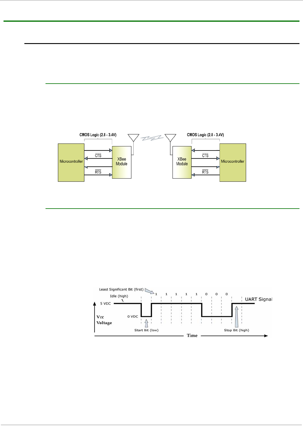
Figure2‐01. SystemDataFlowDiagraminaUART‐interfacedenvironment
(Low‐assertedsignalsdistinguishedwithhorizontallineoversignalname.)
2.1.2. Serial Data
Data enters the XBee module through the DI pin as an asynchronous serial signal. The signal
should idle high when no data is being transmitted.
The UART performs tasks, such as timing and parity checking, that are needed for data
communications. Serial communication consists of two UARTs, one being the XBee's and the other
being the Microcontroller's, configured with compatible parameters (baud rate, parity, start bits,
stop bits, data bits) to have successful communication. Each data packet consists of a start bit
(low), 8 data bits (least significant bit first) and a stop bit (high). The following figure illustrates
the serial bit pattern of data passing through the module.
Figure2‐02. UARTdatapacket0x1F(decimalnumberʺ31ʺ)astransmittedthroughtheXBeeModule
ExampleDataFormatis8‐N‐1(bits‐parity‐#ofstopbits)
DIN (data in) DIN (data in)
DOUT (data out) DOUT (data out)
XBee‐PRO®XSCOEMRFModules
©2011DigiInternational,Inc. 10
2.1.3. Flow Control
Figure2‐03. InternalDataFlowDiagram(Thefivemostcommonly‐usedpinsignalsshown.)
DI (Data In) Buffer and Flow Control
When serial data enters the XBee module through the DI Pin, then the data is stored in the DI
Buffer until it can be transmitted.
When the RO parameter threshold is satisfied (refer to Transmit Mode and Command Descriptions
sections for more information), the module attempts to initialize an RF connection. If the module is
already receiving RF data, the serial data is stored in the module's DI Buffer. If the DI buffer
becomes full, hardware or software flow control must be implemented in order to prevent overflow
(loss of data between the host and XBee OEM RF Module).
How to eliminate the need for flow control:
• Send messages that are smaller than the DI buffer size, which is generally around 1,000
bytes.
• Interface at a lower baud rate (BD parameter) than the fixed RF data rate with the Retries
functionality (RR parameter) disabled.
Two cases in which the DI Buffer may become full and possibly overflow:
• If the serial interface data rate is set higher than the RF data rate of the module, the module
will receive data from the host faster than it can transmit the data over-the-air.
• If the module is receiving a continuous stream of data, monitoring data on a network, or
awaiting acknowledgments for Retries functionality, any serial data that arrives on the DI pin
is placed in the DI Buffer. The data in the DI buffer will be transmitted over-the-air when the
module no longer detects RF data in the network.
Hardware Flow Control (CTS). When the DI buffer is 65 bytes away from being full; by default,
the module de-asserts (high) CTS to signal to the host device to stop sending data [refer to FT
(Flow Control Threshold) and CS (DO2 Configuration) Commands]. CTS is re-asserted after the DI
Buffer has 34 bytes of memory available.
Software Flow Control (XON). XON/XOFF software flow control can be enabled using the FL
(Software Flow Control) command.
DO (Data Out) Buffer and Flow Control
When RF data is received, the data enters the DO buffer and is then sent out the serial port to a
host device. Once the DO Buffer reaches capacity, any additional incoming RF data is lost.
Two cases in which the DO Buffer may become full and possibly overflow:
• If the RF data rate is higher than the set interface data rate of the module, the module will
receive data from the transmitting module faster than it can send the data to the host.
• If the host does not allow the RF module to send data out of the DO buffer because of hard-
ware or software flow control.
Hardware Flow Control (RTS). If RTS is enabled for flow control (RT Parameter = 2), data will
not be sent out the DO Buffer as long as RTS (pin 16) is de-asserted.
Software Flow Control (XOFF). XON/XOFF software flow control can be enabled using the FL
(Software Flow Control) Command. This option only works with ASCII data.

XBee‐PRO®XSCOEMRFModules
©2011DigiInternational,Inc. 11
2.2. Modes of Operation
XBee-PRO® XSC RF Modules operate in five modes.
Figure2‐04. ModesofOperation
2.2.1. Idle Mode
When not receiving or transmitting data, the RF module is in Idle Mode. The module shifts into the
other modes of operation under the following conditions:
• Transmit Mode (Serial data is received in the DI Buffer)
• Receive Mode (Valid RF data is received through the antenna)
• Sleep Mode (Sleep Mode condition is met)
• Command Mode (Command Mode Sequence is issued)
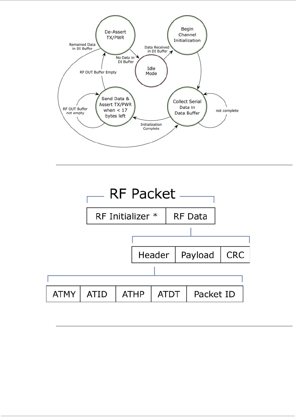
2.2.2. Transmit Mode
When the first byte of serial data is received from the UART in the DI buffer, the modem attempts
to shift to Transmit Mode and initiate an RF connection with other modems. After transmission is
complete, the modem returns to Idle Mode.
RF transmission begins after either of the following criteria is met:
1. RB bytes have been received in the DI buffer and are pending for RF transmission [refer to RB
(Packetization Threshold) command, p34].
- The RB parameter may be set to any value between 1 and the RF packet size (PK), inclusive.
When RB = 0, the packetization threshold is ignored.
2. At least one character has been received in the DI buffer (pending for RF transmission) and RO
time has been observed on the UART [refer to RO (Packetization Timeout) command].
- The timeout can be disabled by setting RO to zero. In this case, transmission will begin after RB
bytes have been received in the DI buffer.
Note: RF reception must complete before the modem is able to enter into Transmit Mode.
After either RB or RO conditions are met, the modem then initializes a communications channel.
[Channel initialization is the process of sending an RF initializer that synchronizes receiving
modems with the transmitting modem. During channel initialization, incoming serial data
accumulates in the DI buffer.]
Serial data in the DI buffer is grouped into RF packets [refer to PK (RF Packet Size)]; converted to
RF data; then transmitted over-the-air until the DI buffer is empty.
RF data, which includes the payload data, follows the RF initializer. The payload includes up to the
maximum packet size (PK Command) bytes. As the transmitting modem nears the end of the
transmission, it inspects the DI buffer to see if more data exists to be transmitted. This could be
the case if more than PK bytes were originally pending in the DI buffer or if more bytes arrived
from the UART after the transmission began. If more data is pending, the transmitting modem
assembles a subsequent packet for transmission.
XBee‐PRO®XSCOEMRFModules
©2011DigiInternational,Inc. 12
RF Packet
The RF packet is the sequence of data used for communicating information between MaxStream
Modems. An RF Packet consists of an RF Initializer and RF Data.
When streaming multiple RF packets, the RF Initializer is only sent in front of the first packet.
RF Initializer
An RF initializer is sent each time a new connection sequence begins. The RF initializer contains
channel information that notifies receiving modems of information such as the hopping pattern
used by the transmitting modem. The first transmission always sends an RF initializer.
An RF initializer can be of various lengths depending on the amount of time determined to be
required to prepare a receiving modem. For example, a wake-up initializer is a type of RF initial-
izer used to wake remote modems from Sleep Mode (Refer to the FH, LH, HT and SM Com-
mands for more information). The length of the wake-up initializer should be longer than the
length of time remote modems are in cyclic sleep.
XBee‐PRO®XSCOEMRFModules
©2011DigiInternational,Inc. 13
Header
The header contains network addressing information that filters incoming RF data. The receiv-
ing modem checks for a matching Hopping Channel (HP parameter), Vendor Identification Num-
ber (ID parameter) and Destination Address (DT parameter). Data that does not pass through
all three network filter layers is discarded.
CRC (Cyclic Redundancy Check)
To verify data integrity and provide built-in error checking, a 16-bit CRC (Cyclic Redundancy
Check) is computed for the transmitted data and attached to the end of each RF packet. On the
receiving end, the receiving modem computes the CRC on all incoming RF data. Received data
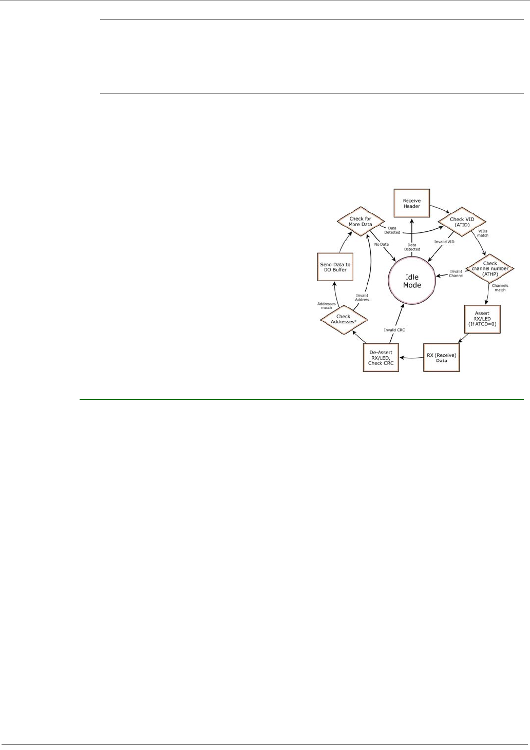
that has an invalid CRC is discarded. Receive Mode
If a module detects RF data while operating in Idle Mode, the module transitions into Receive Mode
to start receiving RF packets.
Figure2‐05. ReceptionofRFData
After a packet is received, the module
checks the CRC (cyclic redundancy check)
to ensure that the data was transmitted
without error. If the CRC data bits on the
incoming packet are invalid, the packet is
discarded. If the CRC is valid, the packet
proceeds to the DO Buffer.
The module returns to Idle Mode after valid
RF data is no longer detected or after an
error is detected in the received RF data. If
serial data is stored in the DI buffer while
the module is in Receive Mode, the serial
data will be transmitted after the module is
finished receiving data and returns to Idle
Mode.
2.2.3. Sleep Mode
Sleep Modes enable the XBee module to operate at minimal power consumption when not in use.
The following Sleep Mode options are available:
•Pin Sleep
•Cyclic Sleep
For the module to transition into Sleep Mode, the module must have a non-zero SM (Sleep Mode)
Parameter and one of the following must occur:
• The module is idle (no data transmission or reception) for a user-defined period of time [Refer
to the ST (Time before Sleep) Command].
• SLEEP is asserted (only for Pin Sleep option).
In Sleep Mode, the module will not transmit or receive data until the module first transitions to
Idle Mode. All Sleep Modes are enabled and disabled using SM Command. Transitions into and out
of Sleep Modes are triggered by various events as shown in the table below.

XBee‐PRO®XSCOEMRFModules
©2011DigiInternational,Inc. 14
Tab le2‐01. SummaryofSleepModeConfigurations
Pin Sleep (SM = 1)
In order to achieve this state, SLEEP pin must be asserted (high). The module remains in Pin Sleep
until the SLEEP pin is de-asserted.
After enabling Pin Sleep, the SLEEP pin controls whether the XBee module is active or in Sleep
Mode. When SLEEP is de-asserted (low), the module is fully operational. When SLEEP is asserted
(high), the module transitions to Sleep Mode and remains in its lowest power-consuming state
until the SLEEP pin is de-asserted. SLEEP is only active if the module is setup to operate in this
mode; otherwise the pin is ignored.
Once in Pin Sleep Mode, CTS is de-asserted (high), indicating that data should not be sent to the
module. The PWR pin is also de-asserted (low) when the module is in Pin Sleep Mode.
Note: The module will complete a transmission or reception before activating Pin Sleep.
Cyclic Sleep (SM = 3-8)
Cyclic Sleep is the Sleep Mode in which the XBee module enters into a low-power state and
awakens periodically to determine if any transmissions are being sent.
When Cyclic Sleep settings are enabled, the XBee module goes into Sleep Mode after a user-
defined period of inactivity (no transmission or reception on the RF channel). The user-defined
period is determined by ST (Time before Sleep) Command.
While the module is in Cyclic Sleep Mode, CTS is de-asserted (high) to indicate that data should
not be sent to the module during this time. When the module awakens to listen for data, CTS is
asserted and any data received on the DI Pin is transmitted. The PWR pin is also de-asserted (low)
when the module is in Cyclic Sleep Mode.
The module remains in Sleep Mode for a user-defined period of time ranging from 0.5 seconds to
16 seconds (SM Parameters 3 through 8). After this interval of time, the module returns to Idle
Mode and listens for a valid data packet for 100 ms. If the module does not detect valid data (on
any frequency), the module returns to Sleep Mode. If valid data is detected, the module
transitions into Receive Mode and receives incoming RF packets. The module then returns to Sleep
Mode after a Period of inactivity that is determined by ST “Time before Sleep” Command.
The module can also be configured to wake from cyclic sleep when SLEEP (pin 9) is de-asserted
(low). To configure a module to operate in this manner, PW (Pin Wake-up) Command must be
issued. Once SLEEP is de-asserted, the module is forced into Idle Mode and can begin transmitting
or receiving data. It remains active until no data is detected for the period of time specified by the
ST Command, at which point it resumes its low-power cyclic state.
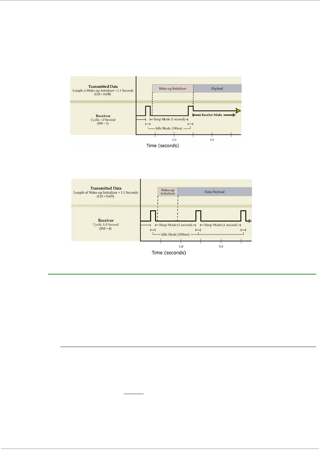
Note: The cyclic interval time defined by SM (Sleep Mode) Command must be shorter than the
interval time defined by LH (Wake-up Initializer Timer).
For example: If SM=4 (Cyclic 1.0 second sleep), the LH Parameter should equal 0x0B ("1.1"
seconds). With these parameters set, there is no risk of the receiving module being asleep for the
duration of wake-up initializer transmission. “Cyclic Scanning” explains in further detail the
relationship between “Cyclic Sleep” and “Wake-up Initializer Timer”
Sleep Mode
Setting Transition into
Sleep Mode Transition out of
Sleep Mode Related
Commands Typical Power
Consumption
(S3)
Typical Power
Consumption
(S3B)
Pin Sleep
(SM = 1)
Microcontroller can shut down and wake
modules by asserting (high) SLEEP (pin 9).
Note: The module will complete a
transmission or reception before activating
Pin Sleep.
De-assert (low)
SLEEP (pin 9). SM 50 µA 2.5uA
Cyclic Sleep
(SM = 3-8)
Automatic transition to Sleep Mode occurs
in cycles as defined by the SM (Sleep
Mode) Command.
Note: The cyclic sleep time interval must be
shorter than the “Wake-up Initializer Timer”
(set by LH Command).
After the cyclic sleep
time interval elapses.
Note: Module can be
forced into Idle Mode
if PW (Pin Wake-up)
Command is enabled.
SM, ST, HT,
LH, PW 76 µA
when sleeping
2.5uA
when sleeping
XBee‐PRO®XSCOEMRFModules
©2011DigiInternational,Inc. 15
Cyclic Scanning. Each RF transmission consists of an RF Initializer and payload. The wake-up
initializer contains initialization information and all receiving modules must wake during the wake-
up initializer portion of data transmission in order to be synchronized with the transmitting module
and receive the data.
Figure2‐06. CorrectConfiguration(LH>SM)
Lengthofthewake‐upinitializerexceedsthetimeintervalofCyclicSleep.Thereceiverisguaranteedtodetect
thewake‐upinitializerandreceivetheaccompanyingpayloaddata.
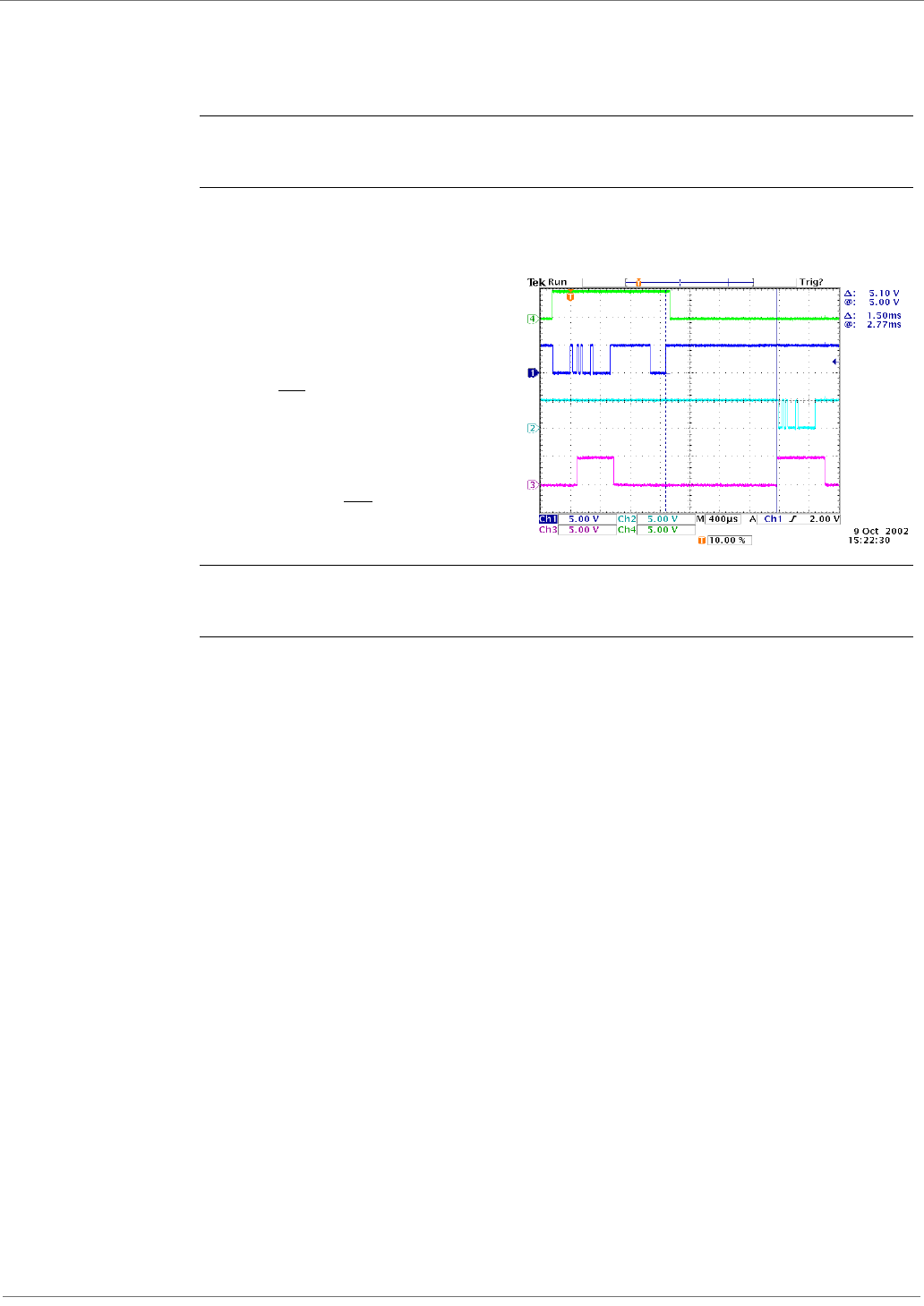
Figure2‐07. IncorrectConfiguration(LH<SM)
Lengthofwake‐upinitializerisshorterthanthetimeintervalofCyclicSleep.Thisconfigurationisvulnerableto
thereceiverwakingandmissingthewake‐upinitializer(andthereforealsotheaccompanyingpayloaddata).
2.2.4. Command Mode
To modify or read module parameters, the module must first enter into Command Mode, the state in
which received characters on the UART are interpreted as commands. Two command types are avail-
able for programming the module:
• AT Commands
• Binary Commands
For modified parameter values to persist in the module registry, changes must be saved to non-vola-
tile memory using WR (Write) Command. Otherwise, parameters are restored to previously saved val-
ues after the module is powered off and then on again.
AT Commands
To Enter AT Command Mode:
• Send the 3-character command sequence “+++” and observe guard times before and after
the command characters. [refer to ‘Default AT Command Mode Sequence’ below.] The ‘Termi-
nal’ tab (or other serial communications software) of the X-CTU Software can be used to enter
the sequence.
[OR]
• Assert (low) the CONFIG pin and either turn the power going to the module off and back on.
(If using a Digi XBIB-R Interface Board, the same result can be achieved by holding the Data-
In line low (also known as a break) while rebooting the module by pressing the reset button
on the module assembly [module assembly = module mounted to an interface board]).

XBee‐PRO®XSCOEMRFModules
©2011DigiInternational,Inc. 16
Default AT Command Mode Sequence (for transition to Command Mode):
• No characters sent for one second [refer to the BT (Guard Time Before) Command]
• Input three plus characters (“+++”) within one second
[refer to the CC (Command Sequence Character) Command.]
• No characters sent for one second [refer to the AT (Guard Time After) Command.]
To Send AT Commands:
Send AT commands and parameters using the syntax shown below.
Figure2‐8.SyntaxforsendingATCommands
To read a parameter value stored in the module register, leave the parameter field blank.
The preceding example would change the module’s Destination Address to “0x1F”. To store the
new value to non-volatile (long term) memory, the Write (ATWR) command must subsequently be
sent before powering off the module.
System Response. When a command is sent to the module, the module will parse and execute
the command. Upon successful execution of a command, the module returns an “OK” message. If
execution of a command results in an error, the module returns an “ERROR” message.
To Exit AT Command Mode:
• If no valid AT Commands are received within the time specified by CT (Command Mode Time-
out) Command, the module automatically returns to Idle Mode.
[OR]
• Send ATCN (Exit Command Mode) Command.
For an example of programming the RF module using AT Commands and descriptions of each config-
urable parameter, refer to the “RF Module Configuration” chapter.
Binary Commands
Sending and receiving parameter values using binary commands is the fastest way to change
operating parameters of the module. Binary commands are used most often to sample signal
strength (RS parameter) and/or error counts; or to change module addresses and channels for
polling systems when a quick response is necessary. Since the sending and receiving of parameter
values takes place through the same data path as 'live' data (received RF payload), follow the CTS
pin as outlined in Figure 2-012 to distinguish between the two types of data (commands vs 'live'
data).
Common questions regarding the use of binary commands:
• What are the implications of asserting CMD while live data is being sent or received?
• After sending serial data, is there a minimum time delay before CMD can be asserted?
• Is a time delay required after CMD is de-asserted before payload data can be sent?
• How to discern between live data and data received in response to a command?
CMD (pin 16) must be asserted in order to send binary commands to the module. The CMD pin can
be asserted to recognize binary commands anytime during the transmission or reception of data.
The status of the CMD signal is only checked at the end of the stop bit as the byte is shifted into
the serial port. The application does not allow control over when data is received, except by
waiting for dead time between bursts of communication.
If the command is sent in the middle of a stream of payload data to be transmitted, the command
will essentially be executed in the order it is received. If the radio is continuously receiving data,
the radio will wait for a break in the received data before executing the command. The CTS signal
will frame the response coming from the binary command request [Figure 2-09].
XBee‐PRO®XSCOEMRFModules
©2011DigiInternational,Inc. 17
A minimum time delay of 100 µs (after the stop bit of the command byte has been sent) must be
observed before pin 5 can be de-asserted. The command executes after all parameters associated
with the command have been sent. If all parameters are not received within 0.5 seconds, the
module aborts the command and returns to Idle Mode.
Note: Binary commands that return only one parameter byte must also be written with two parameter
bytes, 0-padded, LSB first. Refer to “Programming Examples” section [pXX] for a binary programming
example.
Commands can be queried for their current value by sending the command logically ORed (bit-
wise) with the value 0x80 (hexadecimal) with CMD asserted. When the binary value is sent (with
no parameters), the current value of the command parameter is sent back through the DO pin.
Figure2‐09. BinaryCommandWritethenRead
Signal#4isCMD(pin16)
Signal#1istheDIN(pin3)signal
totheradio
Signal#2istheDOUT(pin2)signal
fromtheradio
Signal#3isCTS(pin12)
In this graph, a value was written to a
register and then read out to verify it.
While not in the middle of other received
data, note that the CTS signal outlines the
data response out of the module.
IMPORTANT: For the XBee module to recognize a binary command, the RT (DI2 Configuration) param-
eter must be set to one. If binary programming is not enabled RT = 0 or 2, the module will not recog-
nize that the CMD pin is asserted and therefore will not recognize the data as binary commands.

XBee‐PRO®XSCOEMRFModules
©2011DigiInternational,Inc. 18
3.RFModuleConfiguration
3.1. XBee Programming Examples
For information about entering and exiting AT and Binary Command Modes, refer to the Command
Mode section.
3.1.1. AT Commands
To Send AT Commands (Using the ‘Terminal’ tab of the X-CTU Software)
Note: When using X-CTU Software to program a module, PC com port settings must match the baud
(interface data rate), parity & stop bits parameter settings of the module. Use the 'Com Port Setup'
section of the “PC Settings” tab to configure PC com port settings to match those of the module.
3.1.2. Binary Commands
To Send Binary Commands
Note: CTS is de-asserted high when commands are being executed. Hardware flow control must be
disabled as CTS will hold off parameter bytes.
Example: Utilize the 'Terminal' tab of the X-CTU Software to change the module's DT (Destina-
tion Address) parameter and save the new address to non-volatile memory. This example
requires the installation of Digi’s X-CTU Software and a serial connection to a PC.
Select the ‘Terminal’ tab of the X-CTU Software and enter the following command lines:
Method 1 (One line per command)
Send AT Command
+++
ATDT <Enter>
ATDT1A0D <Enter>
ATWR <Enter>
ATCN <Enter>
System Response
OK <CR> (Enter into Command Mode)
{current value} <CR> (Read Destination Address)
OK <CR> (Modify Destination Address)
OK <CR> (Write to non-volatile memory)
OK <CR> (Exit Command Mode)
Method 2 (Multiple commands on one line)
Send AT Command
+++
ATDT <Enter>
ATDT1A0D,WR,CN <Enter>
System Response
OK <CR> (Enter into Command Mode)
{current value} <CR> (Read Destination Address)
OK <CR> (Execute commands)
Example: Use binary commands to change the XBee module's destination address to 0x1A0D
and save the new address to non-volatile memory.
1. RT Command must be set to "1" in AT Command Mode to enable binary programming.
2. Assert CMD (Pin 16 is driven high). (Enter Binary Command Mode)
3. Send Bytes (parameter bytes must be 2 bytes long):
00
0D
1A
08
(Send DT (Destination Address) Command)
(Least significant byte of parameter bytes
(Most significant byte of parameter bytes)
(Send WR (Write) Command)
4. De-assert CMD (Pin 16 is driven
low) (Exit Binary Command Mode)
Note:Donotsendcom‐
mandstothemodule
duringflashprogram‐
ming(whenparameters
arebeingwrittentothe
moduleregistry).
Waitforthe“OK”sys‐
temresponsethatfol‐
lowstheATWR
commandbeforeenter‐
ingthenextcommand
oruseflowcontrol.

XBee‐PRO®XSCOEMRFModules
©2011DigiInternational,Inc. 19
3.2. Command Reference Table
Table3‐01. ATCommands(TheRFModuleexpectsnumericalvaluesinhexadecimal.ʺdʺdenotesdecimalequivalent.)
AT
Command Binary
Command AT Command Name Range Command Category # Bytes
Returned Factory
Default
*AM 0x3A (58d) Auto-set MY - Networking & Security - -
AT 0x05 (5d) Guard Time After 0x02 – 0xFFFF [x 100 msec] Command Mode Options 2 0x0A (10d)
BD 0x15 (21d) Interface Data Rate
Standard baud rates:
0 – 6
Non-standard baud rates:
0x7D – 0xFFFF
Serial Interfacing 2 0x03 9600bps
BT 0x04 (4d) Guard Time Before 2 – 0xFFFF [x 100 msec] Command Mode Options 2 0x0A (10d)
CC 0x13 (19d) Command Sequence Character 0x20 – 0x7F Command Mode Options 1 0x2B (“+”)
CD 0x28 (40d) DO3 Configuration 0 - 4 Serial Interfacing 1 0
CN 0x09 (9d) Exit AT Command Mode - Command Mode Options - -
CS 0x1F (31d) DO2 Configuration 0 – 4 Serial Interfacing 1 0
CT 0x06 (6d) Command Mode Timeout 0x02 – 0xFFFF [x 100 msec] Command Mode Options 2 0xC8 (200d)
DB RSSI level in dBm of the most recent
packet 0 - 0x70 [read-only] Diagnostics 1
DT 0x00 (0d) Destination Address 0 – 0xFFFF Networking 2 0
E0 0x0A (10d) Echo Off - Command Mode Options - -
E1 0x0B (11d) Echo On - Command Mode Options - -
ER 0x0F (15d) Receive Error Count 0 – 0xFFFF Diagnostics 2 0
FH 0x0D (13d) Force Wake-up Initializer - Sleep (Low Power) - -
FL 0x07 (7d) Software Flow Control 0 – 1 Serial Interfacing 1 0
FR Forces the module to Reset (Special)
FT 0x24 (36d) Flow Control Threshold 0 – (DI buffer – 0x11) [bytes] Serial Interfacing 2 varies
GD 0x10 (16d) Receive Good Count 0 – 0xFFFF Diagnostics 2 0
HP 0x11 (17d) Hopping Channel 0 – 6 Networking 1 0
HT 0x03 (3d) Time before Wake-up Initializer 0 – 0xFFFF [x 100 msec] Sleep (Low Power) 2 0xFFFF
ID 0x27 (39d) Module VID User set table: 0x10 - 0x7FFF
Read-only: 0x8000 – 0xFFFF Networking 2 -
LH 0x0C (12d) Wake-up Initializer Timer 0 – 0xFF [x 100 msec] Sleep (Low Power) 1 1
*MD 0x32 (50d) RF Mode 0 – 4 Networking & Security 1 0
MK 0x12 (18d) Address Mask 0 – 0xFFFF Networking 2 0xFFFF
*MY 0x2A (42d) Source Address 0 – 0xFFFF Networking & Security 2 0xFFFF
NB 0x23 (35d) Parity 0 – 5 Serial Interfacing 1 0
PC 0x1E (30d) Power-up Mode 0 – 1 Command Mode Options 1 0
*PK 0x29 (41d) RF Packet Size 0 - 0x100 [bytes] Serial Interfacing 2 0x40 (64d)
*PL 0x3c (60d) RF Power Level 0-4 (Special) 1 4
PW 0x1D (29d) Pin Wake-up 0 – 1 Sleep (Low Power) 1 0
*RB 0x20 (32d) Packetization Threshold 0 - 0x100 [bytes] Serial Interfacing 2 0x01
RE 0x0E (14d) Restore Defaults - (Special) - -
RN 0x19 (25d) Delay Slots 0 – 0xFF [slots] Networking 1 0
RO 0x21 (33d) Packetization Timeout 0 – 0xFFFF [x 200 µsec] Serial Interfacing 2 0
RP 0x22 (34d) RSSI PWM Timer 0 - 0x7F [x 100 msec] Diagnostics 1 0
RR 0x18 (24d) Retries 0 – 0xFF Networking 1 0
RS 0x1C (28d) RSSI 0x06 – 0x36 [read-only] Diagnostics 1 -
RT 0x16 (22d) DI2 Configuration 0 - 2 Serial Interfacing 1 0
*RZ 0x2C (44d) DI Buffer Size [read-only] Diagnostics - -
SB 0x36 (54d) Stop Bits 0 - 1 Serial Interfacing 1 0
SH 0x25 (37d) Serial Number High 0 – 0xFFFF [read-only] Diagnostics 2 -
SL 0x26 (38d) Serial Number Low 0 – 0xFFFF [read-only] Diagnostics 2 -
SM 0x01 (1d) Sleep Mode 0, 1, 3 - 8 Sleep (Low Power) 1 0
ST 0x02 (2d) Time before Sleep 0x10 – 0xFFFF [x 100 msec] Sleep (Low Power) 2 0x64 (100d)

XBee‐PRO®XSCOEMRFModules
©2011DigiInternational,Inc. 20
NOTE:ATCommandsissuedwithoutaparametervalueareinterpretedasqueriesandwillreturnthecurrentlystoredparameter.
*CommandsonlysupportedonS3Bhardware.
3.3. Command Descriptions
Commands in this section are listed alphabetically. Command categories are designated between
the “< >” symbols that follow each command title. Modules expect numerical values in
hexadecimal and those values are designated by a “0x” prefix.
Modules operating within the same network should contain the same firmware platform to ensure
the same AT Command parameters are supported.
AM (Auto-set MY) Command
AT (Guard Time After) Command
SY 0x17 (23d) Time before Initialization 0 – 0xFF [x 100 msec] Networking 1 0 (disabled)
TR 0x1B (27d) Transmit Error Count 0 – 0xFFFF Diagnostics 2 0
TT 0x1A (26d) Streaming Limit 0 – 0xFFFF [0 = disabled] Networking 2 0xFFFF
VR 0x14 (20d) Firmware Version 0 - 0xFFFF [read-only] Diagnostics 2 -
WR 0x08 (8d) Write - (Special) - -
Command Summary Description
AT Command: ATAM <Networking & Security> AM Command
is used to automatically set the MY
(Source Address) parameter from the
factory-set module serial number. The
address is formed with bits 29, 28 and
13-0 of the serial number (in that
order).
Binary Command: 0x3A (58 decimal)
This command is only supported on S3B
modules.
Command Summary Description
AT Command: ATAT <Command Mode Options> AT
Command is used to set the time-of-
silence that follows the command
sequence character (CC Command). By
default, AT Command Mode will activate
after one second of silence.
Refer to the AT Commands section [p] to
view the default AT Command Mode
Sequence.
Binary Command: 0x05 (5 decimal)
Parameter Range:0x02 – 0xFFFF
[x 100 milliseconds]
Number of bytes returned: 2
Default Parameter Value: 0x0A (10
decimal)
Related Commands: BT (Guard Time
Before), CC (Command Sequence
Character)

XBee‐PRO®XSCOEMRFModules
©2011DigiInternational,Inc. 21
BD (Interface Data Rate) Command
Table3‐02. ParameterSentvs.ParameterStored
BT (Guard Time Before) Command
Command Summary Description
AT Command: ATBD <Serial Interfacing> BD Command allows the user to adjust the
UART interface data rate and thus modify the rate at which
serial data is sent to the module. The new baud rate does not
take effect until the CN (Exit AT Command Mode) Command is
issued. The RF data rate is not affected by the BD Command.
Although most applications will only require one of the seven
standard baud rates, non-standard baud rates are also
supported.
Note: If the serial data rate is set to exceed the fixed RF data
rate of the module, flow control may need to be implemented
as described in the Pin Signals and Flow Control sections of this
manual.
Non-standard Interface Data Rates: When parameter values
outside the range of standard baud rates are sent, the closest
interface data rate represented by the number is stored in the
BD register. For example, a rate of 19200 bps can be set by
sending the following command line “ATBD4B00”. NOTE: When
using X-CTU Software, non-standard interface data rates can
only be set and read using the X-CTU ‘Terminal’ tab. Non-
standard rates are not accessible through the ‘Modem
Configuration’ tab.
When the BD command is sent with a non-standard interface
data rate, the UART will adjust to accommodate the requested
interface rate. In most cases, the clock resolution will cause the
stored BD parameter to vary from the parameter that was sent
(refer to the table below). Reading the BD command (send
“ATBD” command without an associated parameter value) will
return the value that was actually stored to the BD register.
Binary Command: 0x15 (21 decimal)
Parameter Range (Standard baud rates): 0
– 6
(Non-standard baud rates): 0x7D –
0xFFFF (125d – 65535d)
Parameter
Value
BAUD (bps)
Configuration
0 1200
1 2400
2 4800
3 9600
4 19200
5 38400
6 57600
Number of bytes returned: 2
Default Parameter Value: Set to equal
module’s factory-set RF data rate.
BD Parameter Sent (HEX) Interface Data Rate (bps) BD Parameter Stored (HEX)
0 1200 0
4 19,200 4
6 57600 6
12C 300 12B
E100 57600 E883
Command Summary Description
AT Command: ATBT <Command Mode Options> BT
Command is used to set the DI pin
silence time that must precede the
command sequence character (CC
Command) of the AT Command Mode
Sequence. Refer to the AT Commands
section [p] to view the default AT
Command Mode Sequence.
Binary Command: 0x04 (4 decimal)
Parameter Range:2 – 0xFFFF
[x 100 milliseconds]
Default Parameter Value: 0x0A (10
decimal)
Number of bytes returned: 2
Related Commands: AT (Guard Time
After), CC (Command Sequence
Character)

XBee‐PRO®XSCOEMRFModules
©2011DigiInternational,Inc. 22
CC (Command Sequence Character) Command
CD (DO3 Configuration) Command
CN (Exit AT Command Mode) Command
CS (DO2 Configuration) Command
Command Summary Description
AT Command: ATCC <Command Mode Options> CC
Command is used to set the ASCII
character to be used between Guard
Times of the AT Command Mode
Sequence (BT+ CC + AT). The AT
Command Mode Sequence activates AT
Command Mode (from Idle Mode).
Refer to the AT Commands section [p] to
view the default AT Command Mode
Sequence.
Binary Command: 0x13 (19 decimal)
Parameter Range: 0x20 – 0x7F
Default Parameter Value: 0x2B (ASCII “+”
sign)
Number of bytes returned: 1
Related Commands: AT (Guard Time
After), BT (Guard Time Before)
Description
AT Command: ATCD
Binary Command: 0x28 (40 decimal) <Command Mode
Options> CD
Command is used to
define the behavior of
the DO3/RX LED line.
Parameter Range: 0 – 3
Parameter
Value Configuration
0RX LED
1Default high
2Default low
3 (reserved)
4Assert only when packet
addressed to module is sent
Default Parameter Value: 0
Number of bytes returned: 1
Command Summary Description
AT Command: ATCN <Command Mode Options> CN
Command is used to explicitly exit AT
Command Mode.
Binary Command: 0x09 (9 decimal)
Command Summary Description
AT Command: ATCS <Serial Interfacing> CS
Command is used to
select the behavior of
the DO2 pin signal.
This output can
provide RS-232 flow
control, control the TX
enable signal (for RS-
485 or RS-422
operations), or set the
default level for the I/O
line passing function.
By default, DO2
provides RS-232 CTS
(Clear-to-Send) flow
control.
Binary Command: 0x1F (31 decimal)
Parameter Range:0 – 4
Parameter
Value Configuration
0RS-232 flow control
1 RS-485 TX enable low
2high
3 RS-485 TX enable high
4low
Default Parameter Value: 0
Number of bytes returned: 1
Minimum Firmware Version Required:
4.27D

XBee‐PRO®XSCOEMRFModules
©2011DigiInternational,Inc. 23
CT (Command Mode Time out) Command
DB (RSSI in dBm) Command
DT (Destination Address) Command
E0 (Echo Off) Command
Command Summary Description
AT Command: ATCT <Command Mode Options> CT
Command sets the amount of time
before AT Command Mode terminates
automatically. After a CT time of
inactivity, the module exits AT
Command Mode and returns to Idle
Mode. AT Command Mode can also be
exited manually using CN (Exit AT
Command Mode) Command.
Binary Command: 0x06 (6 decimal)
Parameter Range:0x02 – 0xFFFF
[x 100 milliseconds]
Default Parameter Value: 0xC8 (200
decimal, 20 seconds)
Number of bytes returned: 2
Command Summary Description
AT Command: ATDB <Diagnostics> DB command returns the
signal level of the last packet received in
dBm. This reading is useful for
determining range characteristics of the
Modules under various conditions of
noise and distance.
Once the command is issued, the
module will return the value in dBm.
0x32 (50d) = -50 dBm (strong signal),
and 0x64 (100d) = -100 dBm (weak
signal).
Binary Command: Not available
Parameter Range:00x00 to 0x70
[read-only]
Number of bytes returned: returned: 1
Related Commands: RS (RSSI Level)
Command Summary Description
AT Command: ATDT <Networking> DT Command is used to
set the networking address of a Module.
Modules use three network layers –
Vendor Identification Number (ATID),
Channels (ATHP), and Destination
Addresses (ATDT). DT Command
assigns an address to a module that
enables it to communicate only with
other modules having the same
addresses. All modules that share the
same Destination Address can
communicate freely with each other.
Modules in the same network with a
different Destination Address (than that
of the transmitter) will listen to all
transmissions to stay synchronized, but
will not send any of the data out their
serial ports.
Binary Command: 0x00
Parameter Range:0 – 0xFFFF
Default Parameter Value: 0
Number of bytes returned: 2
Related Commands: HP (Hopping
Channel), ID (Module VID), MK (Address
Mask)
Command Summary Description
AT Command: ATE0 <Command Mode Options> E0
Command turns off character echo in AT
Command Mode. By default, echo is off.
Binary Command: 0x0A (10 decimal)

XBee‐PRO®XSCOEMRFModules
©2011DigiInternational,Inc. 24
E1 (Echo On) Command
ER (Receive Error Count) Command
FH (Force Wake-up Initializer) Command
FL (Software Flow Control) Command
Command Summary Description
AT Command: ATE1 <Command Mode Options> E1
Command turns on the echo in AT
Command Mode. Each typed character
will be echoed back to the terminal
when ATE1 is active. E0 is the default.
Binary Command: 0x0B (11 decimal)
Command Summary Description
AT Command: ATER <Diagnostics> Set/Read the receive-
error. The error-count records the
number of packets partially received
then aborted on a reception error. This
value returns to 0 after a reset and is not
non-volatile (Value does not persist in
the module’s memory after a power-up
sequence). Once the “Receive Error
Count” reaches its maximum value (up
to 0xFFFF), it remains at its maximum
count value until the maximum count
value is explicitly changed or the
module is reset.
Binary Command: 0x0F (15 decimal)
Parameter Range:0 – 0xFFFF
Default Parameter Value: 0
Number of bytes returned: 2
Related Commands: GD (Receive Good
Count)
Command Summary Description
AT Command: ATFH <Sleep (Low Power)> FH Command is
used to force a Wake-up Initializer to be
sent on the next transmit. WR (Write)
Command does not need to be issued
with FH Command.
Use only with cyclic sleep modes active
on remote modules.
Binary Command: 0x0D (13 decimal)
Command Summary Description
AT Command:
ATFL
<Serial Interfacing> FL Command
is used to configure software flow
control. Hardware flow control is
implemented with the Module as
the DO2 pin (), which regulates
when serial data can be transferred
to the module. FL Command can be
used to allow software flow control
to also be enabled. XON character
used is 0x11 (17 decimal). XOFF
character used is 0x13 (19
decimal).
Binary Command: 0x07 (7
decimal)
Parameter Range: 0 – 1
Parameter Value Configuration
0Disable software
flow control
1Enable software
flow control
Default Parameter Value: 0
Number of bytes returned: 1

XBee‐PRO®XSCOEMRFModules
©2011DigiInternational,Inc. 25
FR (Force Reset) Command
FT (Flow Control Threshold) Command
GD (Receive Good Count) Command
HP (Hopping Channel) Command
Command Summary Description
AT Command: ATFR <Special> FR command is used in order
to reset the module through the UART.
The characters “OK”<CR> will be
returned and the module will reset
100ms
Binary Command: Not available
Command Summary Description
AT Command: ATFT <Serial Interfacing> Flow Control
Threshold - Set or read flow control
threshold. De-assert CTS and/or send
XOFF when FT bytes are in the UART
receive buffer. Re-assert CTS when less
than FT - 16 bytes are in the UART receive
buffer.
Binary Command: 0x24 (36 decimal)
Parameter Range:0 – (DI buffer size minus
0x11 bytes)
Default Parameter Value: DI Buffer size
minus 0x11 (17 decimal)
Number of bytes returned: 2
Minimum Firmware Version Required:
4.27B
Command Summary Description
AT Command: ATGD
Binary Command: 0x10 (16 decimal) <Diagnostics> Set/Read the count of
good received RF packets. Parameter
value is reset to 0 after every reset and is
not non-volatile (Value does not
persist in the module’s memory after a
power-up sequence). Once the
“Receive Good Count” reaches its
maximum value (up to 0xFFFF), it
remains at its maximum count value until
the maximum count value is
manually changed or the module is reset.
Parameter Range:0 – 0xFFFF
Default Parameter Value: 0
Number of bytes returned: 2
Related Commands: ER (Receive Error
Count)
Command Summary Description
AT Command: ATHP <Networking> HP Command is used to
set the module’s hopping channel
number. A channel is one of three layers
of addressing available to the
module. In order for modules to
communicate with each other, the
modules must have the same channel
number since each network uses a
different hopping sequence. Different
channels can be used to prevent
modules in one network from listening
to transmissions of another.
Binary Command: 0x11 (17 decimal)
Parameter Range:0 – 6
Default Parameter Value: 0
Number of bytes returned: 1
Related Commands: DT (Destination
Address), ID (Module VID), MK (Address
Mask)

XBee‐PRO®XSCOEMRFModules
©2011DigiInternational,Inc. 26
HT (Time before Wake-up Initializer) Command
ID (Modem VID) Command
Command Summary Description
AT Command: ATHT <Sleep (Low Power)> If any modules within range are running
in a “Cyclic Sleep” setting, a wake-up initializer must be used
by the transmitting module for sleeping modules to remain
awake [refer to the LH (“Wake-up InitializerTimer”) Command].
When a receiving module in Cyclic Sleep wakes, it must detect
the wake-up initializer in order to remain awake and
receive data. The value of HT Parameter tells the transmitter,
“After a period of inactivity (no transmitting or receiving)
lasting HT amount of time, send a long wake-up initializer”. HT
Parameter should be set to match the inactivity time out
[specified by ST (Time before Sleep) Command]
used by the receiver(s). From the receiving module perspective,
after HT time elapses and the inactivity
time out [ST Command] is met, the receiver goes into cyclic
sleep. In cyclic sleep, the receiver wakes once per sleep interval
to check for a wakeup initializer. When a wake-up initializer is
detected, the module will stay awake to receive data. The
wake-up initializer must be longer than the
cyclic sleep interval to ensure that sleeping modules detect
incoming data. When HT time elapses, the transmitter then
knows that it needs to send a long Wake-up Initializer for all
receivers to be able to remain awake and
receive the next transmission. Matching HT to the time
specified by ST on the receiving module guarantees that all
receivers will detect the next transmission.
Binary Command: 0x03 (3 decimal)
Parameter Range:0 – 0xFFFF
[x 100 milliseconds]
Default Parameter Value: 0xFFFF (means
that long wake-up initializer will not be
sent)
Number of bytes returned: 2
Related Commands: LH (Wake-up
Initializer Timer), SM (Sleep Mode), ST
(Time before Sleep)
Command Summary Description
AT Command: ATID <Networking> Set/Read the “Vendor
Identification Number”. Only modems
with matching IDs can communicate
with each other. Modules with non-
matching
VIDs will not receive unintended data
transmission.
Binary Command: 0x27 (39 decimal)
Parameter Range (user-set table) 0x10 -
0x7FFFF
(Factory-set and read-only) 0x8000 –
0xFFFF
Number of bytes returned: 2

XBee‐PRO®XSCOEMRFModules
©2011DigiInternational,Inc. 27
LH (Wake-up Initializer Timer) Command
MD (RF Mode) Command
Command Summary Description
AT Command: ATLH <Sleep (Low Power)> LH Command
adjusts the duration of time for which
the RF initializer is sent.
When receiving modules are put into
Cyclic Sleep Mode, they power-down
after a period of inactivity [specified by
ST (Time before Sleep) Command] and
will periodically awaken and listen
for transmitted data. In order for the
receiving modules to remain awake, they
must detect~35ms of the wake-up
initializer. LH Command must be used
whenever a receiver is operating in
Cyclic Sleep Mode. This lengthens
the Wake-up Initializer to a specific
amount of time (in tenths of a second).
The Wake-up Initializer Time must be
longer than the cyclic sleep time that is
determined by SM (Sleep Mode)
Command. If the wake-up initializer
time were less than the Cyclic Sleep
interval, the connection would be at risk
of missing the wake-up initializer
transmission. Refer to Figures 3.1 & 3.2
of the SM Command description to view
diagrams of correct and incorrect
configurations. The images help
visualize the importance that the value
of LH be greater than the value of SM.
Binary Command: 0x0C (12 decimal)
Parameter Range:0 – 0xFF
[x 100 milliseconds]
Default Parameter Value: 1
Number of bytes returned: 1
Related Commands: HT (Time before
Wake-up Initializer), SM (Sleep Mode), ST
(Time before Sleep)
Command Summary Description
AT Command: ATMD <Networking & Security> The MD
command is used to select/read the RF
Mode (Peer-to-peer, Multi-Stream or
Repeater Modes) of the module.
Multi-Streaming Mode enables exclusive
connections in point-to-multipoint
networks. Refer to the Multi-Streaming
Mode section [p43] for more information
regarding how these parameter values
affect other parameter values.
Repeater Mode enables longer range via
an intermediary module. When MD=3,
the module will act as a “store and
forward” repeater. Any packets not
addressed to this node will be repeated.
A Repeater End Node (MD=4) handles
repeated messages, but will not forward
the data over-the-air. Refer to the
Repeater Mode section [p38] for more
information.
Binary Command: 0x32 (50 decimal)
Parameter Range: 0 – 4
Default Parameter Value: 0
Number of bytes returned: 1
Related Commands: CB (Connection
Duration Time out), CE (Connection
Inactivity Time out), CM (Connection
Message), DC (Disconnect)
This command is only supported on S3B
modules.
Parameter Configuration
0Peer-to-Peer
(transparent operation)
1Multi-Steam Base
2Multi-Steam Remote
3Repeater & End Node
4End Node

XBee‐PRO®XSCOEMRFModules
©2011DigiInternational,Inc. 28
MK (Address Mask) Command
MY (Source Address) Command
NB (Parity) Command
Command Summary Description
AT Command: ATMK <Networking> MK Command is used to
set/read the Address Mask.
All data packets contain the Destination
Address of the transmitting module.
When an RF data packet is received, the
transmitter’s Destination Address is
logically “ANDed” (bitwise) with the
Address Mask of the receiver. The
resulting value must match the
Destination Address or the
Address Mask of the receiver for the
packet to be received and sent out the
module’s DO serial port. If the “ANDed”
value does not match either the
Destination Address or the Address
Mask of the receiver, the packet is
discarded. (All “0” values are treated as
“irrelevant” values and are ignored.)
Binary Command: 0x12 (18 decimal)
Parameter Range:0 – 0xFFFF
Default Parameter Value: 0xFFFF
(Destination address (DT parameter) of
the transmitting module must exactly
match the destination address of the
receiving module.)
Number of bytes returned: 2
Related Commands: DT (Destination
Address), HP (Hopping Channel), ID
(Module VID)
Command Summary Description
AT Command: ATMY <Networking & Security> Set/Read the
source address of the module.
Refer to the Addressing section [p36] of
the RF Communication Modes chapter
for more information.
Binary Command: 0x2A (42 decimal)
Parameter Range: 0 – 0xFFFF
Default Parameter Value: 0xFFFF
(Disabled – the DT (Destination Address)
parameter serves as both source and
destination address.)
Number of bytes returned: 2
Related Commands: DT (Destination
Address), HP (Hopping Channel), ID
(Modem VID), MK (Address Mask), AM
(Auto-set MY)
This command is only supported on S3B
modules.
Command Summary Description
AT Command: ATNB <Serial Interfacing>
Select/Read parity
settings for UART
communications.
Binary Command: 0x23 (35 decimal)
Parameter Range:0 – 4 (S3 Hardware)
0-5 (S3B Hardware)
Parameter
Value Configuration
08-bit (no parity or
7-bit (any parity)
18-bit even
28-bit odd
38-bit mark
48-bit space
5 9-bit data (S3B Hardware)
Default Parameter Value: 0
Number of bytes returned: 1

XBee‐PRO®XSCOEMRFModules
©2011DigiInternational,Inc. 29
PC (Power-up to AT Mode) Command
PK (RF Packet Size) Command
PL (Module Power Level) Command
Command Summary Description
AT Command: ATPC <Command Mode
Options> PC
Command allows the
module to power-up
directly into AT
Command Mode from
reset or power-on. If
PC Command is
enabled with SM
Parameter set to 1, DI3
(pin 9) can be used to
enter the
module into AT
Command Mode. When
the DI3 pin is de-
asserted (low),
the module will wake-
up in AT Command
Mode. This behavior
allows module
DTR emulation.
Binary Command: 0x1E (30 decimal)
Parameter Range:0 – 1
Parameter
Value Configuration
0 Power-up to Idle Mode
1Power-up to
AT Command Mode
Default Parameter Value: 0
Number of bytes returned: 1
Command Summary Description
AT Command: ATPK <Serial Interfacing> Set/Read the
maximum size of the RF packets sent
out a transmitting module. The
maximum packet size can be used along
with the RB and RO parameters to
implicitly set the channel dwell time.
Changes to this parameter may have a
secondary effect on the RB (Packet
Control Characters) parameter. RB must
always be less than or equal to PK. If PK
is changed to a value less than the
current value of RB, RB is automatically
lowered to be equal to PK.
Binary Command: 0x29 (41 decimal)
Parameter Range: 0 – 0x100 [Bytes]
Default Parameter Value: 0x40 (64
decimal)
Number of bytes returned: 2
Related Commands: RB (Packetization
Threshold), RO (Packetization Time out)
This command is only supported on S3B
modules.
Command Summary Description
AT Command: ATPL <Special Commands> Set/Read the power level at which the RF
module transmits conducted power. This command is only
supported on S3B hardware. Power level 4 is calibrated and the
other power levels are approximate.
Binary Command: 0x3C (60 decimal)
Parameter Range:0 – 4
Parameter
Value Configuration
0 +7.0 dBm
1 +15.0dBm
2 +18.0dBm
3 +21.0dBm
4 +24.0 dBm
Default Parameter Value: 4
Number of bytes returned: 1
This command is only supported on S3B
hardware

XBee‐PRO®XSCOEMRFModules
©2011DigiInternational,Inc. 30
PW (Pin Wake-up) Command
RB (Packetization Threshold) Command
RE (Restore Defaults) Command
Command Summary Description
AT Command: ATPW <Sleep (Low Power)> Under normal operation, a module in
Cyclic Sleep Mode cycles from an active state to a low-power
state at regular intervals until data is ready to be received. If
the PW Parameter is set to 1, SLEEP (pin 2) can be used to wake
the module from Cyclic Sleep. If the SLEEP pin
is de-asserted (low), the module will be fully operational and
will not go into Cyclic Sleep. Once SLEEP is asserted, the
module will remain active for the period of time specified by ST
(Time before Sleep) Command, and will return to Cyclic Sleep
Mode (if no data is ready to be transmitted). PW
Command is only valid if Cyclic Sleep has been enabled.
Binary Command: 0x1D (29 decimal)
Parameter Range:0 – 1
Parameter
Value Configuration
0 Disabled
1Enabled
Default Parameter Value: 0
Number of bytes returned: 1
Related Commands: SM (Sleep Mode), ST
(Time before Sleep)
Command Summary Description
AT Command: ATRB <Serial Interfacing> RF transmission will
commence when data is in the DI Buffer
and either of the following criteria are
met:
• RO times out on the UART receive lines
(ignored if RO = 0)
• RB characters have been received by
the UART (ignored if RB = 0)
If PK is lowered below the value of RB; RB
is automatically lowered to match PK.
Note: RB and RO criteria only apply to
the first packet of a multi-packet
transmission. If data remains in the DI
Buffer after the first packet,
transmissions will continue in streaming
manner until there is no data left in the
DI Buffer (UART receive buffer).
Binary Command: 0x20 (32 decimal)
Parameter Range: 0 – 0x100 [Bytes]
(Maximum value equals the current value
of PK Parameter (up to 0x100 HEX (800
decimal))
Default Parameter Value: 1
Number of bytes returned: 2
Related Commands: PK (RF Packet Size),
RO (Packetization Time out)
This command is only supported on S3B
modules.
Command Summary Description
AT Command: ATRE <Diagnostics> RE Command restores all
configurable parameters to factory
default settings. However, RE Command
will not write the default values to
non-volatile (persistent) memory. Unless
the WR (Write) Command is
issued after the RE command, the
default settings will not be saved in the
event of module reset or power-down.
Binary Command: 0x0E (14 decimal)

XBee‐PRO®XSCOEMRFModules
©2011DigiInternational,Inc. 31
RN (Delay Slots) Command
RO (Packetization Time out) Command
RP (RSSI PWM Timer) Command
Command Summary Description
AT Command: ATRN <Networking> RN Command is only
applicable if retries have been
enabled [RR (Retries) Command], or if
forced delays will be inserted into
a transmission [refer to TT (Streaming
Limit) Command]. RN Command is
used to adjust the time delay that the
transmitter inserts before attempting
to resend a packet. If the transmitter
fails to receive an acknowledgement
after sending a packet, it will insert a
random number of delay slots
(ranging from 0 to (RN minus 1)) before
attempting to resend the packet.
Each delay slot lasts for a period of
38ms.
If two modules attempted to transmit at
the same time, the random time
delay after packet failure would allow
one of the two modules to transmit
the packet successfully, while the other
would wait until the channel
opens up to begin transmission.
Binary Command: 0x19 (25 decimal)
Parameter Range:0 – 0xFF [slots]
Default Parameter Value: 0 (no delay slots
inserted)
Number of bytes returned: 1
Command Summary Description
AT Command: ATRO <Serial Interfacing> RO Command is used
to specify/read the time of
silence (no bytes received) after which
transmission begins. After a serial
byte is received and if no other byte is
received before the RO time out,
the transmission will start.
Binary Command: 0x21 (33 decimal)
Parameter Range:0 – 0xFFFF [x 200 µs]
Default Parameter Value: 0
Number of bytes returned: 2
Command Summary Description
AT Command: ATRP <Diagnostics> RP Command is used to
enable a PWM (“Pulse Width Modulation”)
output on the Config pin which is
calibrated to show the level the
received RF signal is above the sensitivity
level of the module. The PWM
pulses vary from zero to 95 percent. Zero
percent means the received RF
signal is at or below the published
sensitivity level of the module. The
following
table shows levels above sensitivity and
PWM values.
The total period of the PWM output is
8.32 ms. There are 40 steps in the
PWM output and therefore the minimum
step size is 0.208 ms.
Binary Command: 0x22 (34 decimal)
Parameter Range:0 - 0x7F
[x 100 milliseconds]
Default Parameter Value: 0 (disabled)
Number of bytes returned: 1

XBee‐PRO®XSCOEMRFModules
©2011DigiInternational,Inc. 32
Tab le3‐03. PWMChart
A non-zero value defines the time that the PWM output will be active with the RSSI value of the
last received RF packet. After the set time when no RF packets are received, the PWM output will
be set low (0 percent PWM) until another RF packet is received. The PWM output will also be set
low at power-up. A parameter value of 0xFF permanently enables the PWM output and it will
always reflect the value of the last received RF packet.
PWM output shares the Config input pin. When the module is powered, the Config pin will be an
input. During the power-up sequence, the Config pin will be read to determine whether the module
is going into AT Command Mode. After this, if RP parameter is a non-zero value, the Config pin will
be configured as an output and set low until the first RF packet is received. With a non-zero RP
parameter, the Config pin will be an input for RP ms after power up.
RZ (DI Buffer Size) Command
RR (Retries) Command
dBm above Sensitivity PWM percentage
(high period / total period)
10 47.5 %
20 62.5 %
30 77.5 %
Command Summary Description
AT Command: ATRZ <Diagnostics> The RZ command is used
to read the size of the DI buffer (UART RX
(Receive)).
Note: The DO buffer size can be
determined by multiplying the DI buffer
size by 1.5.
Binary Command: 0x2C (44 decimal)
Parameter Range:Read-only
Number of bytes returned: 1
This command is only supported on S3B
modules.
Command Summary Description
AT Command: ATRR Networking> RR Command specifies the
number of retries that can be sent
for a given RF packet. Once RR Command
is enabled (set to a non-zero
value), RF packet acknowledgements and
retries are enabled. After transmitting
a packet, the transmitter will wait to
receive an acknowledgement
from a receiver. If the acknowledgement
is not received in the period of
time specified by the RN (Delay Slots)
Command, the transmitter will transmit
the original packet again. The packet will
be transmitted repeatedly
until an acknowledgement is received or
until the packet has been sent RR
times.
Note: For retries to work correctly, all
modules in the system must have
retries enabled.
Binary Command: 0x18 (24 decimal)
Parameter Range:0 – 0xFF
Default Parameter Value: 0 (disabled)
Number of bytes returned: 1

XBee‐PRO®XSCOEMRFModules
©2011DigiInternational,Inc. 33
RS (RSSI) Command
RT (DI2 Configuration) Command
SB (Stop Bits) Command
SH (Serial Number High) Command
Command Summary Description
AT Command: ATRS <Diagnostics> RS Command returns the
signal level of the last packet
received. This reading is useful for
determining range characteristics of the
modules under various conditions of
noise and distance.
Once the command is issued, the
module will return a value between 0x6
and 0x36 where 0x36 represents a very
strong signal level and 0x4 indicates
a low signal level.
Binary Command: 0x1C (28 decimal)
Parameter Range: 0x06 – 0x36 [read-
only]
Number of bytes returned: 1
Command Summary Description
AT Command: ATRT <Serial Interfacing> RT
command is used to
dictate the behavior of
the
DI2/RTS/CMD line. RT
Command must be
issued to enable RTS
flow control
or binary
programming.
Binary Command: 0x16 (22 decimal)
Parameter Range:0 – 2
Parameter
Value Configuration
0 disabled
1 Enable Binary Programming
2Enable Flow Control
Default Parameter Value: 0
Number of bytes returned: 1
Command Summary Description
AT Command: ATSB SB Command is used to
set/read the number of
stop bits in the data
packets.
Binary Command: 0x36 (54 decimal)
Parameter Range:0 – 1
Parameter
Value Configuration
01 stop bits
12 stop bits
Default Parameter Value: 0
Number of bytes returned: 1
Command Summary Description
AT Command: ATSH <Diagnostics> Read the serial number
high word of the module.
Binary Command: 0x25 (37 decimal)
Parameter Range:0 – 0xFFFF [read-only]
Number of bytes returned: 2
Related Commands: SL (Serial Number
Low)

XBee‐PRO®XSCOEMRFModules
©2011DigiInternational,Inc. 34
SL (Serial Number Low) Command
SM (Sleep Mode) Command
ST (Time before Sleep) Command
Command Summary Description
AT Command: ATSL <Diagnostics> Read the serial number
low word of the module.
Binary Command: 0x26 (38 decimal)
Parameter Range:0 – 0xFFFF [read-only]
Number of bytes returned: 2
Related Commands: SH (Serial Number
High)
Command Summary Description
AT Command: ATSM <Sleep Mode (Low Power)> SM Command is used to adjust
Sleep Mode settings. By default, Sleep Mode is disabled and the
module remains continually active. SM Command allows the
module to run in a lower-powerstate and be configured in one
of eight settings. Cyclic Sleep settings wake the module after
the amount of time designated
by SM Command. If the module detects a wake-up initializer
during the time it is awake, it will synchronize with the
transmitter and start receiving data after the wake-up
initializer runs its duration. Otherwise, it
returns to Sleep Mode and continue to cycle in and out of
inactivity until the Wake-up Initializer is detected. If a Cyclic
Sleep setting is chosen, the ST, LH and HT parameters must
also be set as described in the “Sleep
Mode” section of this manual.
Binary Command: 0x01
Parameter Range:0,1 3-8
Parameter
Value Configuration
0 Disabled
1Pin Sleep
3
Cyclic 0.5 second sleep
(Module wakes every 0.5
seconds)
4 Cyclic 1.0 second sleep
5 Cyclic 2.0 second sleep
6 Cyclic 4.0 second sleep
7 Cyclic 8.0 second sleep
8 Cyclic 16.0 second sleep
Default Parameter Value: 0
Number of bytes returned: 1
Related Commands:
For Pin Sleep – PC (Power-up Mode), PW
(Pin Wake-up)
For Serial Port Sleep – ST (Time before
Sleep)
For Cyclic Sleep – ST (Time before Sleep),
LH (Wake-up Initializer Timer), HT (Time
Before Wake-up Initializer), PW (Pin Wake-
up)
Command Summary Description
AT Command: ATST <Sleep Mode (Low Power)> ST
Command sets the period of time (in
tenths of seconds) in which the module
remains inactive before entering
into Sleep Mode. For example, if the ST
Parameter is set to 0x64 (100
decimal), the module will enter into
Sleep mode after 10 seconds of
inactivity
(no transmitting or receiving). This
command can only be used if
Cyclic Sleep or Serial Port Sleep Mode
settings have been selected using
SM (Sleep Mode) Command.
Binary Command: 0x02
Parameter Range:0x10 – 0xFFFF
[x 100 milliseconds]
Default Parameter Value: 0x64 (100
decimal)
Number of bytes returned: 2
Related Commands: SM (Sleep Mode), LH
(Wake-up Initializer Timer), HT (Time
before Wake-up Initializer)

XBee‐PRO®XSCOEMRFModules
©2011DigiInternational,Inc. 35
SY (Time before Initialization) Command
TR (Transmit Error Count) Command
Command Summary Description
AT Command: ATSY <Networking> SY Command keeps a communication channel
open as long as module transmits or receives before the active
connection expires. It can be used to reduce latency in a query/
response sequence and should be set 100 ms longer than the
delay between transmissions. This command allows multiple
Modules to share a hopping channel
for a given amount of time after receiving data. By default, all
packets include an RF initializer that contains channel
information used to synchronize any listening receivers to the
transmitter’s hopping pattern. Once a new module comes
within range, it is able to instantly synchronize to the
transmitter and start receiving data. If no new modules are
introduced into the system, the synchronization information
becomes redundant once modules
have become synchronized.
SY Command allows the modules to remove this information
from the RF Initializer after the initial synchronization. For
example, changing the SY Parameter to 0x14 (20 decimal)
allows all modules to remain in sync for 2
seconds after the last data packet was received.
Synchronization information is not re-sent unless transmission
stops for more than 2 seconds. This command allows
significant savings in packet transmission time.
Warning: Not recommended for use in an interference-prone
environment. Interference can break up the session and the
communications channel will not be available again until SY
time expires. With SY set to zero, the channel session is opened
and closed with each transmission - resulting in a more robust
link with more latency.
Binary Command: 0x17 (23 decimal)
Parameter Range:0 – 0xFF
[x 100 milliseconds]
Default Parameter Value: 0 (Disabled -
channel initialization information is sent
with each RF packet.)
Number of bytes returned: 1
Command Summary Description
AT Command: ATTR <Diagnostics> TR Command records the
number of retransmit failures.
This number is incremented each time a
packet is not acknowledged within
the number of retransmits specified by
the RR (Retries) Command. It
therefore counts the number of packets
that were not successfully received
and have been dropped.
The TR Parameter is not non-volatile and
will therefore be reset to zero
each time the module is reset.
Binary Command: 0x1B (27 decimal)
Parameter Range:0 – 0xFFFF
Default Parameter Value: 0
Number of bytes returned: 2
Related Commands: RR (Retries)

XBee‐PRO®XSCOEMRFModules
©2011DigiInternational,Inc. 36
TT (Streaming Limit) Command
Command Summary Description
AT Command: ATTT <Networking> TT Command defines a
limit on the number of bytes that can
be sent out before a random delay is
issued. TT Command is used to simulate
full-duplex behavior.
If a module is sending a continuous
stream of RF data, a delay is inserted
which stops its transmission and allows
other modules time to transmit
(once it sends number of bytes specified
by TT Command). Inserted random
delay lasts between 1 & ‘RN + 1’ delay
slots, where each delay slot
lasts 38 ms.
Binary Command: 0x1A (26 decimal)
Parameter Range:0 – 0xFFFF (0 =
disabled)
Default Parameter Value: 0xFFFF (65535
decimal)
Number of bytes returned: 2
Related Commands: RN (Delay Slots)
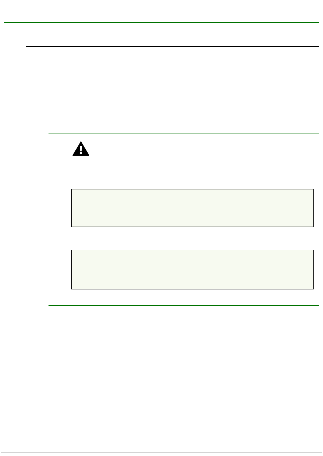
XBee‐PRO®XSCOEMRFModules
©2011DigiInternational,Inc. 37
AppendixA:AgencyCertifications
FCC (United States) Certification
The XBee-PRO® XSC OEM RF Module complies with Part 15 of the FCC rules and regulations.
Compliance with the labeling requirements, FCC notices and antenna usage guidelines is required.
In order to operate under Digi’s FCC Certification, OEMs/integrators must comply with the
following regulations:
Labeling Requirements
WARNING: The Original Equipment Manufacturer (OEM) must ensure that FCC labeling
requirements are met. This includes a clearly visible label on the outside of the final
product enclosure that displays the text shown in the figure below.
FigureA‐01. RequiredFCCLabelforOEMproductscontainingtheXBee‐PRO®XSCOEMRFModule.
XBEE PRO S3
OR
XBEE PRO S3B
FCC Notices
IMPORTANT: The XBee-PRO® XSC OEM RF Module has been certified by the FCC for use with
other products without any further certification (as per FCC section 2.1091). Modifications not
expressly approved by Digi could void the user's authority to operate the equipment.
IMPORTANT: OEMs must test final product to comply with unintentional radiators (FCC section
15.107 & 15.109) before declaring compliance of their final product to Part 15 of the FCC Rules.
IMPORTANT: The RF module has been certified for remote and base radio applications. If the
module will be used for portable applications, the device must undergo SAR testing.
This equipment has been tested and found to comply with the limits for a Class B digital device,
pursuant to Part 15 of the FCC Rules. These limits are designed to provide reasonable protection
against harmful interference in a residential installation. This equipment generates, uses and can
radiate radio frequency energy and, if not installed and used in accordance with the instructions,
may cause harmful interference to radio communications. However, there is no guarantee that
interference will not occur in a particular installation.
If this equipment does cause harmful interference to radio or television reception, which can be
determined by turning the equipment off and on, the user is encouraged to try to correct the
1. The system integrator must ensure that the text provided with this device [Figure A-01] is
placed on the outside of the final product and within the final product operation manual.
2. The XBee-PRO® XSC OEM RF Module may only be used with antennas that have been
tested and approved for use with this module Refer to to Table A-1.
Contains FCC ID: MCQ-XBEEXSC
The enclosed device complies with Part 15 of the FCC Rules. Operation is subject to the following two
conditions: (i.) this device may not cause harmful interference and (ii.) this device must accept any inter-
ference received, including interference that may cause undesired operation.
Contains FCC ID: MCQ-XBPS3B
The enclosed device complies with Part 15 of the FCC Rules. Operation is subject to the following two
conditions: (i.) this device may not cause harmful interference and (ii.) this device must accept any inter-
ference received, including interference that may cause undesired operation.
XBee‐PRO®XSCOEMRFModules
©2011DigiInternational,Inc. 38
interference by one or more of the following measures: Re-orient or relocate the receiving
antenna, Increase the separation between the equipment and receiver, Connect equipment and
receiver to outlets on different circuits, or Consult the dealer or an experienced radio/TV technician
for help.
Limited Modular Approval
This is an RF module approved for Limited Modular use operating as a mobile transmitting device
with respect to section 2.1091 and is limited to OEM installation for Mobile and Fixed applications
only. During final installation, end-users are prohibited from access to any programming
parameters. Professional installation adjustment is required for setting module power and antenna
gain to meet EIRP compliance for high gain antenna(s).
Final antenna installation and operating configurations of this transmitter including antenna gain
and cable loss must not exceed the EIRP of the configuration used for calculating MPE. Grantee
(Digi) must coordinate with OEM integrators to ensure the end-users and installers of products
operating with the module are provided with operating instructions to satisfy RF exposure
requirements.
The FCC grant is valid only when the device is sold to OEM integrators. Integrators are instructed
to ensure the end-user has no manual instructions to remove, adjust or install the device.
FCC-approved Antennas
WARNING: This device has been tested with Reverse Polarity SMA connectors with the
antennas listed in the tables of this section. When integrated into OEM products, fixed
antennas require installation preventing end-users from replacing them with non-
approved antennas. Antennas not listed in the tables must be tested to comply with FCC
Section 15.203 (unique antenna connectors) and Section 15.247 (emissions).
Fixed Base Station and Mobile Applications
Digi RF Modules are pre-FCC approved for use in fixed base station and mobile applications. When
the antenna is mounted at least 20cm (8") from nearby persons, the application is considered a
mobile application.
Portable Applications and SAR Testing
When the antenna is mounted closer than 20cm to nearby persons, then the application is
considered “portable” and requires an additional test be performed on the final product. This test
is called Specific Absorption Rate (SAR) testing and measures the emissions from the module and
how they affect the person.
RF Exposure
This statement must be included as a CAUTION statement in OEM product manuals.
WARNING: This equipment is approved only for mobile and base station transmitting
devices. Antenna(s) used for this transmitter must be installed to provide a separation
distance of at least 20 cm from all persons and must not be co-located or operating in
conjunction with any other antenna or transmitter.
IC (Industry Canada) Certification
Labeling requirements for Industry Canada are similar to those of the FCC. A clearly visible label
on the outside of the final product enclosure must display one of the following text:
For XBEE PRO S3 Contains Model: XBEEXSC, IC: 1846A-XBEEXSC
OR
For XBEEPRO S3B Contains Model: XBPS3B, IC: 1846A-XBPS3B
Integrator is responsible for its product to comply with IC ICES-003 & FCC Part 15, Sub. B -
Unintentional Radiators. ICES-003 is the same as FCC Part 15 Sub. B and Industry Canada accepts
FCC test report or CISPR 22 test report for compliance with ICES-003.

XBee‐PRO®XSCOEMRFModules
©2011DigiInternational,Inc. 39
Transmitter Antennas
This device has been designed to operate with the antennas listed below, and having a maximum
gain of 15.1 dB. Antennas not included in this list or having a gain greater than 15.1 dB are strictly
prohibited for use with this device. The required antenna impedance is 50 ohms.
Operation is subject to the following two conditions: (1) this device may not cause interference,
and (2) this device must accept any interference, including interference that may cause undesired
operation of the device.
To reduce potential radio interference to other users, the antenna type and its gain should be so
chosen that the equivalent isotopically radiated power (e.i.r.p.) is not more than that permitted for
successful communication
Antenna Options: 900 MHz Antenna Listings
Table A-01. Antennas approved for use with the XBee-PRO XSC OEM RF Module
Part Number Type Connector Gain Application Cable Loss or
Power Reduction
for S3B Radio
Omni-directional antennas
A09-F0 Fiberglass Base RPN 0 dBi Fixed 0dB
A09-F1 Fiberglass Base RPN 1.0 dBi Fixed 0dB
A09-F2 Fiberglass Base RPN 2.1 dBi Fixed 0dB
A09-F3 Fiberglass Base RPN 3.1 dBi Fixed 0dB
A09-F4 Fiberglass Base RPN 4.1 dBi Fixed 0dB
A09-F5 Fiberglass Base RPN 5.1 dBi Fixed 0dB
A09-F6 Fiberglass Base RPN 6.1 dBi Fixed 0dB
A09-F7 Fiberglass Base RPN 7.1 dBi Fixed 0dB
A09-F8 Fiberglass Base RPN 8.1 dBi Fixed 0dB
A09-F9 Base Station RPSMAF 9.2dBi Fixed 0dB
A09-W7 Wire Base Station RPN 7.1 dBi Fixed 0dB
A09-F0 Fiberglass Base RPSMA 0 dBi Fixed 0dB
A09-F1 Fiberglass Base RPSMA 1.0 dBi Fixed 0dB
A09-F2 Fiberglass Base RPSMA 2.1 dBi Fixed 0dB
A09-F3 Fiberglass Base RPSMA 3.1 dBi Fixed 0dB
A09-F4 Fiberglass Base RPSMA 4.1 dBi Fixed 0dB
A09-F5 Fiberglass Base RPSMA 5.1 dBi Fixed 0dB
A09-F6 Fiberglass Base RPSMA 6.1 dBi Fixed 0dB
A09-F7 Fiberglass Base RPSMA 7.1 dBi Fixed 0dB
A09-F8 Fiberglass Base RPSMA 8.1 dBi Fixed 0dB
A09-M7 Base Station RPSMAF 7.2dBi Fixed 0dB
A09-W7SM Wire Base Station RPSMA 7.1 dBi Fixed 0dB
A09-F0TM Fiberglass Base RPTNC 0 dBi Fixed 0dB
A09-F1TM Fiberglass Base RPTNC 1.0 dBi Fixed 0dB
A09-F2TM Fiberglass Base RPTNC 2.1 dBi Fixed 0dB
A09-F3TM Fiberglass Base RPTNC 3.1 dBi Fixed 0dB
A09-F4TM Fiberglass Base RPTNC 4.1 dBi Fixed 0dB
A09-F5TM Fiberglass Base RPTNC 5.1 dBi Fixed 0dB
A09-F6TM Fiberglass Base RPTNC 6.1 dBi Fixed 0dB
A09-F7TM Fiberglass Base RPTNC 7.1 dBi Fixed 0dB
A09-F8TM Fiberglass Base RPTNC 8.1 dBi Fixed 0dB
A09-W7TM Wire Base Station RPTNC 7.1 dBi Fixed 0dB

XBee‐PRO®XSCOEMRFModules
©2011DigiInternational,Inc. 40
A09-HSM-7 Straight half-wave RPSMA 3.0 dBi Fixed / Mobile 0dB
A09-HASM-675 Articulated half- RPSMA 2.1 dBi Fixed / Mobile 0dB
A09-HABMM-P6I Articulated half- MMCX 2.1 dBi Fixed / Mobile 0dB
A09-HABMM-6-P6I Articulated half- MMCX 2.1 dBi Fixed / Mobile 0dB
A09-HBMM-P6I Straight half-wave MMCX 2.1 dBi Fixed / Mobile 0dB
A09-HRSM Right angle half- RPSMA 2.1 dBi Fixed 0dB
A09-HASM-7 Articulated half- RPSMA 2.1 dBi Fixed 0dB
A09-HG Glass mounted RPSMA 2.1 dBi Fixed 0dB
A09-HATM Articulated half- RPTNC 2.1 dBi Fixed 0dB
A09-H Half-wave dipole RPSMA 2.1 dBi Fixed 0dB
A09-HBMMP6I 1/2 wave antenna MMCX 2.1dBi Mobile 0dB
A09-QBMMP6I 1/4 wave antenna MMCX 1.9 dBi Mobile 0dB
A09-QI 1/4 wave integrated
wire antenna Integrated 1.9 dBi Mobile 0dB
29000187 Helical Integrated -2.0 dBi Fixed/Mobile 0dB
A09-QW Quarter-wave wire Permanent 1.9 dBi Fixed / Mobile 0dB
A09-QRAMM 3 “Quarter-wave MMCX 2.1 dBi Fixed / Mobile 0dB
A09-QSM-3 Quarter-wave RPSMA 1.9 dBi Fixed / Mobile 0dB
A09-QSM-3H Heavy duty quarter- RPSMA 1.9 dBi Fixed / Mobile 0dB
A09-QBMM-P6I Quarter-wave w/ 6” MMCX 1.9 dBi Fixed / Mobile 0dB
A09-QHRN Miniature Helical Permanent -1 dBi Fixed / Mobile 0dB
A09-QHSN Miniature Helical Permanent -1 dBi Fixed / Mobile 0dB
A09-QHSM-2 2” Straight RPSMA 1.9 dBi Fixed / Mobile 0dB
A09-QHRSM-2 2" Right angle RPSMA 1.9 dBi Fixed / Mobile 0dB
A09-QHRSM-170 1.7" Right angle RPSMA 1.9 dBi Fixed / Mobile 0dB
A09-QRSM-380 3.8" Right angle RPSMA 1.9 dBi Fixed / Mobile 0dB
A09-QAPM-520 5.2” Articulated Permanent 1.9 dBi Fixed / Mobile 0dB
A09-QSPM-3 3” Straight screw Permanent 1.9 dBi Fixed / Mobile 0dB
A09-QAPM-3 3” Articulated screw Permanent 1.9 dBi Fixed / Mobile 0dB
A09-QAPM-3H 3” Articulated screw Permanent 1.9 dBi Fixed / Mobile 0dB
A09-DPSM-P12F omni directional RPSMA 3.0 dBi Fixed 0dB
A09-D3NF-P12F omni directional RPN 3.0 dBi Fixed 0dB
A09-D3SM-P12F omni directional w/ RPSMA 3.0 dBi Fixed 0dB
A09-D3PNF omni directional RPN 3.0 dBi Fixed 0dB
A09-D3TM-P12F omni directional w/ RPTNC 3.0 dBi Fixed 0dB
A09-D3PTM omni directional RPTNC 3.0 dBi Fixed 0dB
A09-M0SM Mag Mount RPSMA 0 dBi Fixed 0dB
A09-M2SM Mag Mount RPSMA 2.1 dBi Fixed 0dB
A09-M3SM Mag Mount RPSMA 3.1 dBi Fixed 0dB
A09-M5SM Mag Mount RPSMA 5.1 dBi Fixed 0dB
A09-M7SM Mag Mount RPSMA 7.1 dBi Fixed 0dB
A09-M8SM Mag Mount RPSMA 8.1 dBi Fixed 0dB
A09-M0TM Mag Mount RPTNC 0 dBi Fixed 0dB
A09-M2TM Mag Mount RPTNC 2.1 dBi Fixed 0dB
A09-M3TM Mag Mount RPTNC 3.1 dBi Fixed 0dB
A09-M5TM Mag Mount RPTNC 5.1 dBi Fixed 0dB
A09-M7TM Mag Mount RPTNC 7.1 dBi Fixed 0dB
A09-M8TM Mag Mount RPTNC 8.1 dBi Fixed 0dB

XBee‐PRO®XSCOEMRFModules
©2011DigiInternational,Inc. 41
Yagi antennas
A09-Y6 2 Element Yagi RPN 6.1 dBi Fixed / Mobile 0dB
A09-Y7 3 Element Yagi RPN 7.1 dBi Fixed / Mobile 0dB
A09-Y8 4 Element Yagi RPN 8.1 dBi Fixed / Mobile 0dB
A09-Y9 4 Element Yagi RPN 9.1 dBi Fixed / Mobile 0dB
A09-Y10 5 Element Yagi RPN 10.1 dBi Fixed / Mobile 0dB
A09-Y11 6 Element Yagi RPN 11.1 dBi Fixed / Mobile 0dB
A09-Y12 7 Element Yagi RPN 12.1 dBi Fixed / Mobile 0dB
A09-Y13 9 Element Yagi RPN 13.1 dBi Fixed / Mobile 0.8dB
A09-Y14 10 Element Yagi RPN 14.1 dBi Fixed / Mobile 1.8dB
A09-Y14 12 Element Yagi RPN 14.1 dBi Fixed / Mobile 1.8dB
A09-Y15 13 Element Yagi RPN 15.1 dBi Fixed / Mobile 2.8dB
A09-Y15 15 Element Yagi RPN 15.1 dBi Fixed / Mobile 2.8dB
A09-Y6TM 2 Element Yagi RPTNC 6.1 dBi Fixed / Mobile 0dB
A09-Y7TM 3 Element Yagi RPTNC 7.1 dBi Fixed / Mobile 0dB
A09-Y8TM 4 Element Yagi RPTNC 8.1 dBi Fixed / Mobile 0dB
A09-Y9TM 4 Element Yagi RPTNC 9.1 dBi Fixed / Mobile 0dB
A09-Y10TM 5 Element Yagi RPTNC 10.1 dBi Fixed / Mobile 0dB
A09-Y11TM 6 Element Yagi RPTNC 11.1 dBi Fixed / Mobile 0dB
A09-Y12TM 7 Element Yagi RPTNC 12.1 dBi Fixed / Mobile 0dB
A09-Y13TM 9 Element Yagi RPTNC 13.1 dBi Fixed / Mobile 0.8dB
A09-Y14TM 10 Element Yagi RPTNC 14.1 dBi Fixed / Mobile 1.8dB
A09-Y14TM 12 Element Yagi RPTNC 14.1 dBi Fixed / Mobile 1.8dB
A09-Y15TM 13 Element Yagi RPTNC 15.1 dBi Fixed / Mobile 2.8dB
A09-Y15TM 15 Element Yagi RPTNC 15.1 dBi Fixed / Mobile 2.8dB

XBee‐PRO®XSCOEMRFModules
©2011DigiInternational,Inc. 42
AppendixB:AdditionalInformation
1-Year Warranty
WARRANTY PERIOD: Digi warranties hardware Product for a period of one (1) year.
WARRANTY PROCEDURE: Upon return of the hardware Product Digi will, at its option, repair or
replace Product at no additional charge, freight prepaid, except as set forth below. Repair parts
and replacement Product will be furnished on an exchange basis and will be either reconditioned or
new. All replaced Product and parts become the property of Digi. If Digi determines that the
Product is not under warranty, it will, at the Customers option, repair the Product using current
Digi standard rates for parts and labor, and return the Product UPS Ground at no charge in or out
of warranty.
Contact Digi
Technical Support: Phone. (801) 765-9885
Live Chat. www.digi.com
Online Support. http://www.digi.com/support/eservice/login.jsp