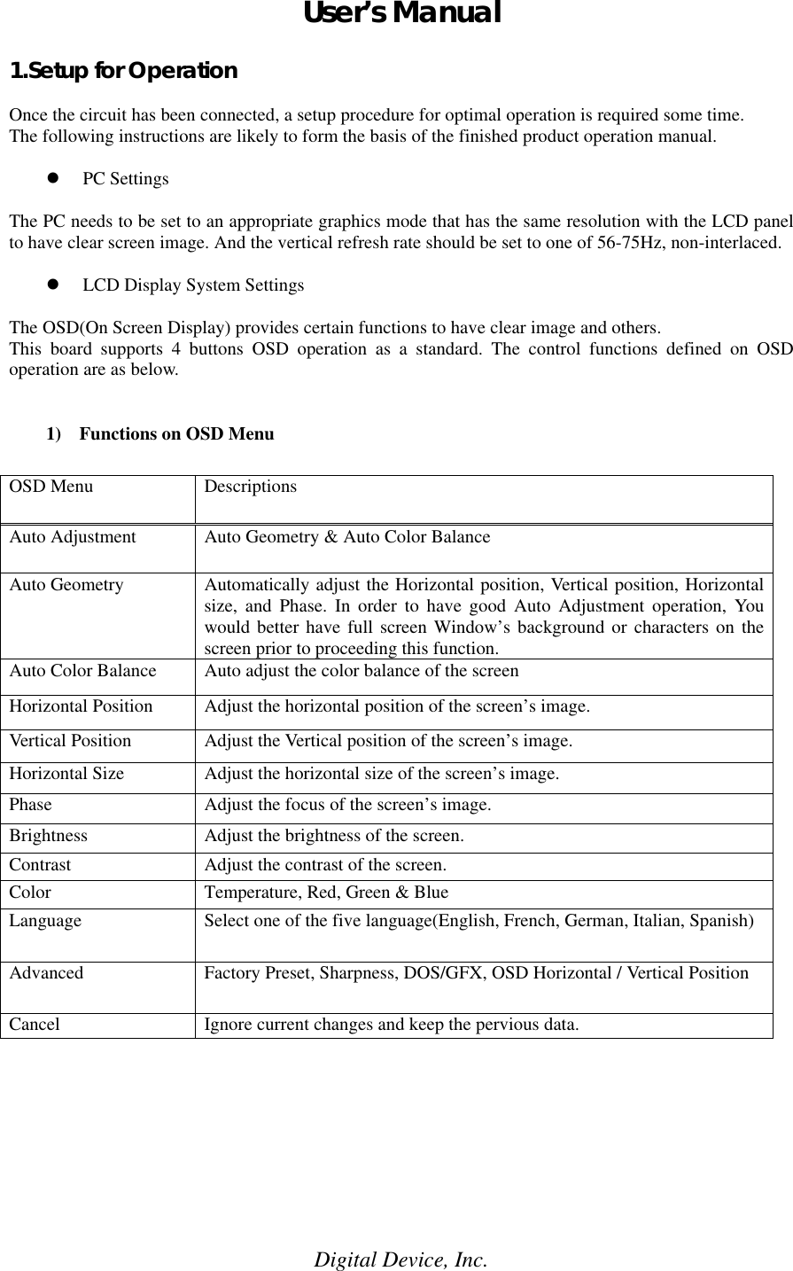
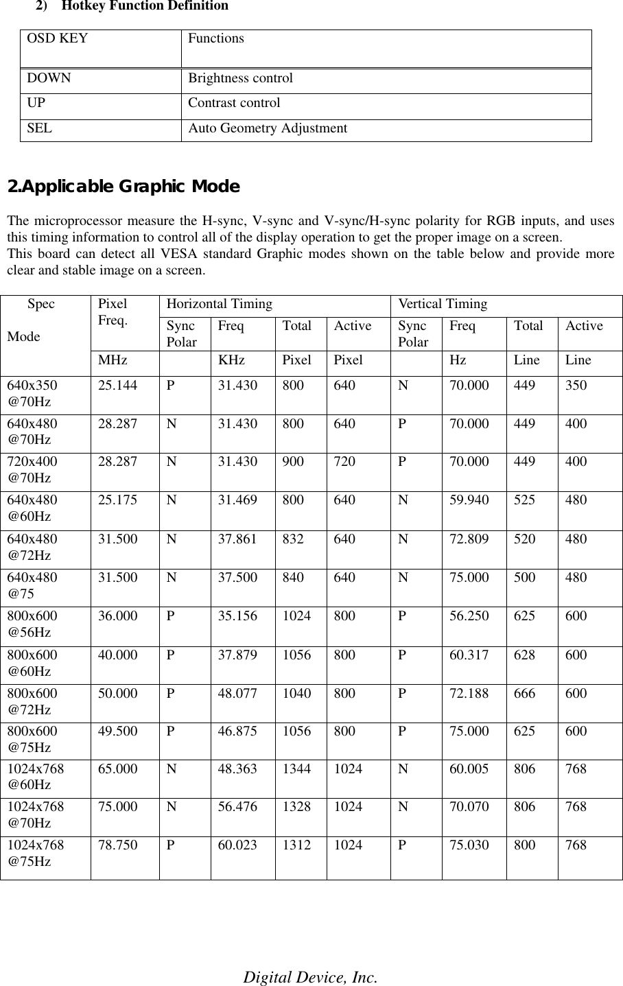
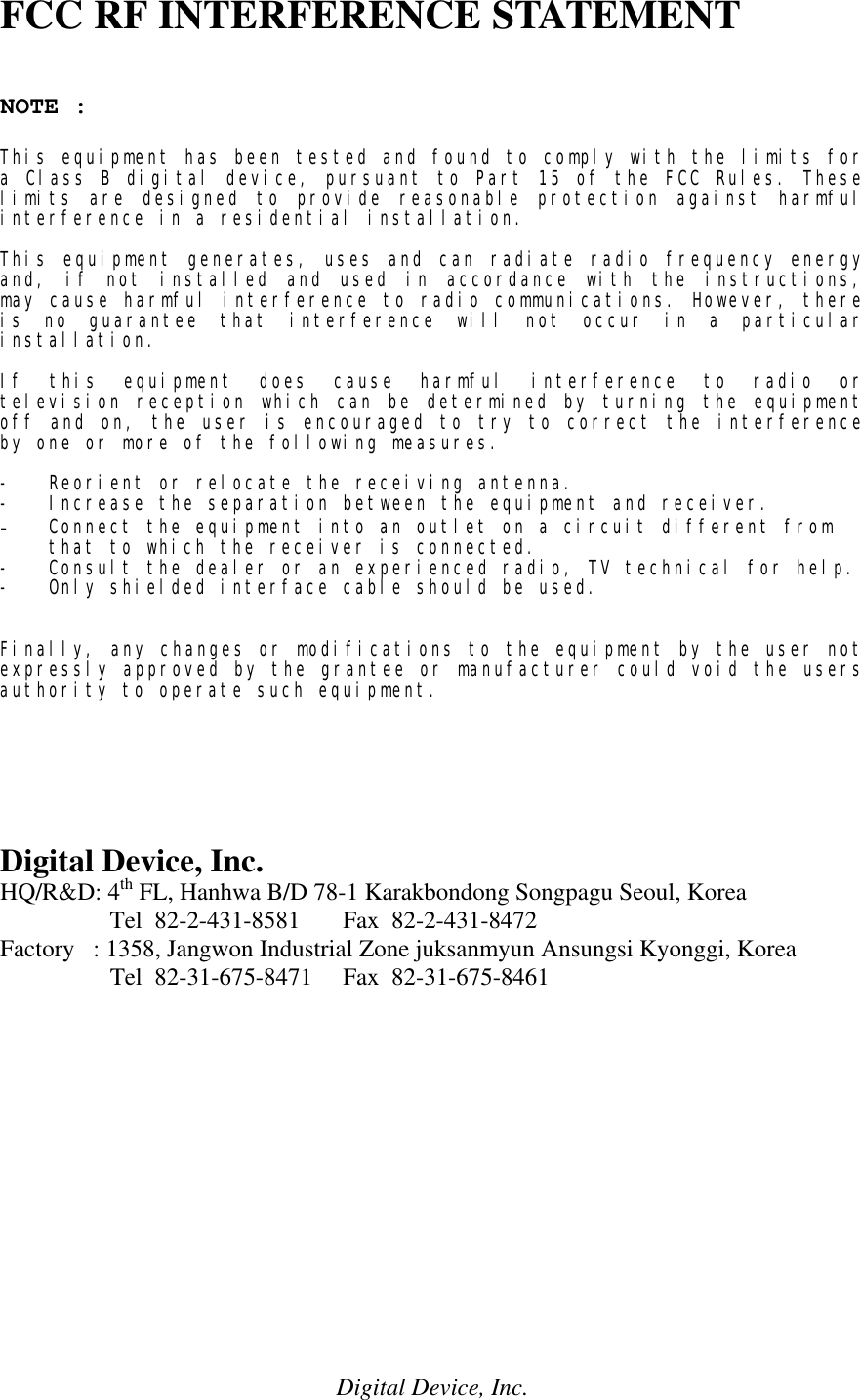
Digital Device LL500H 15 inch LCD Monitor User Manual UserManual

Digital Device Inc. 15 inch LCD Monitor UserManual

users manual

Digital Device, Inc.User’s Manual1.Setup for OperationOnce the circuit has been connected, a setup procedure for optimal operation is required some time.The following instructions are likely to form the basis of the finished product operation manual.l PC SettingsThe PC needs to be set to an appropriate graphics mode that has the same resolution with the LCD panelto have clear screen image. And the vertical refresh rate should be set to one of 56-75Hz, non-interlaced.l LCD Display System SettingsThe OSD(On Screen Display) provides certain functions to have clear image and others.This board supports 4 buttons OSD operation as a standard. The control functions defined on OSDoperation are as below.1) Functions on OSD MenuOSD Menu DescriptionsAuto Adjustment Auto Geometry & Auto Color BalanceAuto Geometry Automatically adjust the Horizontal position, Vertical position, Horizontalsize, and Phase. In order to have good Auto Adjustment operation, Youwould better have full screen Window’s background or characters on thescreen prior to proceeding this function.Auto Color Balance Auto adjust the color balance of the screenHorizontal Position Adjust the horizontal position of the screen’s image.Vertical Position Adjust the Vertical position of the screen’s image.Horizontal Size Adjust the horizontal size of the screen’s image.Phase Adjust the focus of the screen’s image.Brightness Adjust the brightness of the screen.Contrast Adjust the contrast of the screen.Color Temperature, Red, Green & BlueLanguage Select one of the five language(English, French, German, Italian, Spanish)Advanced Factory Preset, Sharpness, DOS/GFX, OSD Horizontal / Vertical PositionCancel Ignore current changes and keep the pervious data.
Digital Device, Inc.2) Hotkey Function DefinitionOSD KEY FunctionsDOWN Brightness controlUP Contrast controlSEL Auto Geometry Adjustment2.Applicable Graphic ModeThe microprocessor measure the H-sync, V-sync and V-sync/H-sync polarity for RGB inputs, and usesthis timing information to control all of the display operation to get the proper image on a screen.This board can detect all VESA standard Graphic modes shown on the table below and provide moreclear and stable image on a screen.Horizontal Timing Vertical TimingPixelFreq. SyncPolar Freq Total Active SyncPolar Freq Total ActiveSpecModeMHz KHz Pixel Pixel Hz Line Line640x350@70Hz 25.144 P31.430 800 640 N70.000 449 350640x480@70Hz 28.287 N31.430 800 640 P70.000 449 400720x400@70Hz 28.287 N31.430 900 720 P70.000 449 400640x480@60Hz 25.175 N31.469 800 640 N59.940 525 480640x480@72Hz 31.500 N37.861 832 640 N72.809 520 480640x480@75 31.500 N37.500 840 640 N75.000 500 480800x600@56Hz 36.000 P35.156 1024 800 P56.250 625 600800x600@60Hz 40.000 P37.879 1056 800 P60.317 628 600800x600@72Hz 50.000 P48.077 1040 800 P72.188 666 600800x600@75Hz 49.500 P46.875 1056 800 P75.000 625 6001024x768@60Hz 65.000 N48.363 1344 1024 N60.005 806 7681024x768@70Hz 75.000 N56.476 1328 1024 N70.070 806 7681024x768@75Hz 78.750 P60.023 1312 1024 P75.030 800 768
Digital Device, Inc.FCC RF INTERFERENCE STATEMENTNOTE :This equipment has been tested and found to comply with the limits fora Class B digital device, pursuant to Part 15 of the FCC Rules. Theselimits are designed to provide reasonable protection against harmfulinterference in a residential installation.This equipment generates, uses and can radiate radio frequency energyand, if not installed and used in accordance with the instructions,may cause harmful interference to radio communications. However, thereis no guarantee that interference will not occur in a particularinstallation.If this equipment does cause harmful interference to radio ortelevision reception which can be determined by turning the equipmentoff and on, the user is encouraged to try to correct the interferenceby one or more of the following measures.-   Reorient or relocate the receiving antenna.-   Increase the separation between the equipment and receiver.- Connect the equipment into an outlet on a circuit different from    that to which the receiver is connected.-   Consult the dealer or an experienced radio, TV technical for help.-   Only shielded interface cable should be used.Finally, any changes or modifications to the equipment by the user notexpressly approved by the grantee or manufacturer could void the usersauthority to operate such equipment.Digital Device, Inc.HQ/R&D: 4th FL, Hanhwa B/D 78-1 Karakbondong Songpagu Seoul, Korea                  Tel  82-2-431-8581       Fax  82-2-431-8472Factory   : 1358, Jangwon Industrial Zone juksanmyun Ansungsi Kyonggi, Korea                  Tel  82-31-675-8471     Fax  82-31-675-8461

Navigation menu