Digital Security Controls SKYROUTE SKYROUTE, SKYROUTE MAX or SKYROUTE UT User Manual LINKS2150 v1 4W im na 29004010 r1
Digital Security Controls Ltd. SKYROUTE, SKYROUTE MAX or SKYROUTE UT LINKS2150 v1 4W im na 29004010 r1
Contents
- 1. Users Manual
- 2. revised manual wrt FCC correspondence 18131
Users Manual
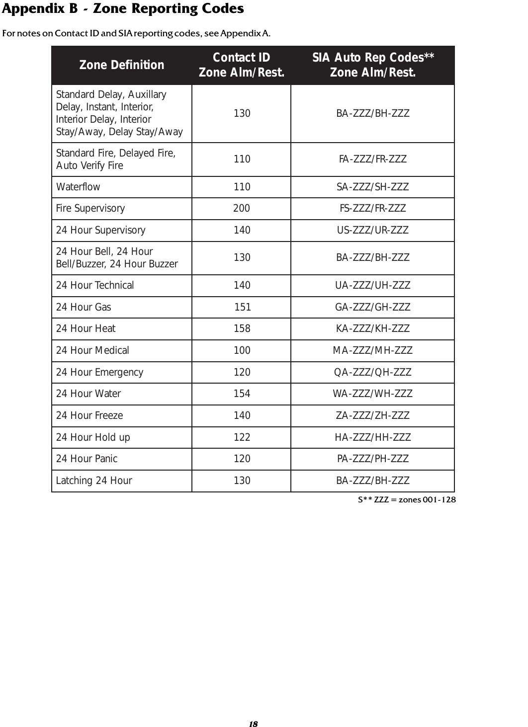
![Table of ContentsGeneric Reporting 5Description ................................................................... 5Normal Alarm Condition ................................................ 5Notice .......................................................................... 5STEP 4 - Programming Sections 6Configuration Options - Section [006] ............................. 6Skyroute max Transceiver SID (System ID) - Section [007] . 6Skyroute max Test Time - Section [010] ........................... 6Test Transmission Day Mask - Section [011] .................... 6STEP 5 - Activating the Skyroute max Transceiver 6Calling Connect24 ......................................................... 6Transmitting and Receiving ............................................. 6Testing Your Control to the Central Station 6Skyroute max Programming with PC4020[00][18]Skyroute max Programming 7[00][18] Skyroute max Programming .............................. 7[006]Skyroute max Configuration Options ....................... 7[007Home SID Number .................................................. 7[010]Skyroute max Test Time ......................................... 7[011]Test Transmission Day Mask ................................... 7[013]Skyroute max Test Rates ........................................ 7Sections [030]-[047] ..................................................... 8Skyroute max Transceiver Trouble Shooting 12Antenna Relocation Diagram 13Supervised Power Supply Connection Diagram 14Standard Connection with PC4020 15For Your Records 16Appendix A – Reporting Codes for SIA and Contact ID 17Appendix B - Zone Reporting codes 18Limited Warranty BACKContents iiImportant Information ................................................. iiSkyroute max Glossary of Terms iiIntroducing the Skyroute max Transceiver 1Specifications .............................................................. 1Communications Method ............................................ 1Dual Path Communications ......................................... 1Antenna ....................................................................... 1RF Power Output ......................................................... 1Power Supply Ratings .................................................. 1Dimension ................................................................... 1Weight ......................................................................... 1Operating Temperature .................................................. 1How the Skyroute max Transceiver Works 1Cellemetry Communication ............................................ 1Installation 2Mounting the Skyroute max Transceiver .......................... 2Combus Connection ....................................................... 2Bell IN Terminal ............................................................. 2Bell OUT Terminal .......................................................... 2Tamper Terminal ........................................................... 2Secure Installation ......................................................... 2Connection Diagram ...................................................... 2STEP 1 - Location of the Skyroute max Unit 3Relocating the Antenna 3Mounting the Antenna ................................................... 3Relocating the Skyroute max Transceiver 4Skyroute max Transceiver Trouble Supervision 4STEP 2 - Enrolling Skyroute max with 4020 4STEP 3 - Defaulting the Skyroute max5i](https://usermanual.wiki/Digital-Security-Controls/SKYROUTE.Users-Manual/User-Guide-128389-Page-3.png)
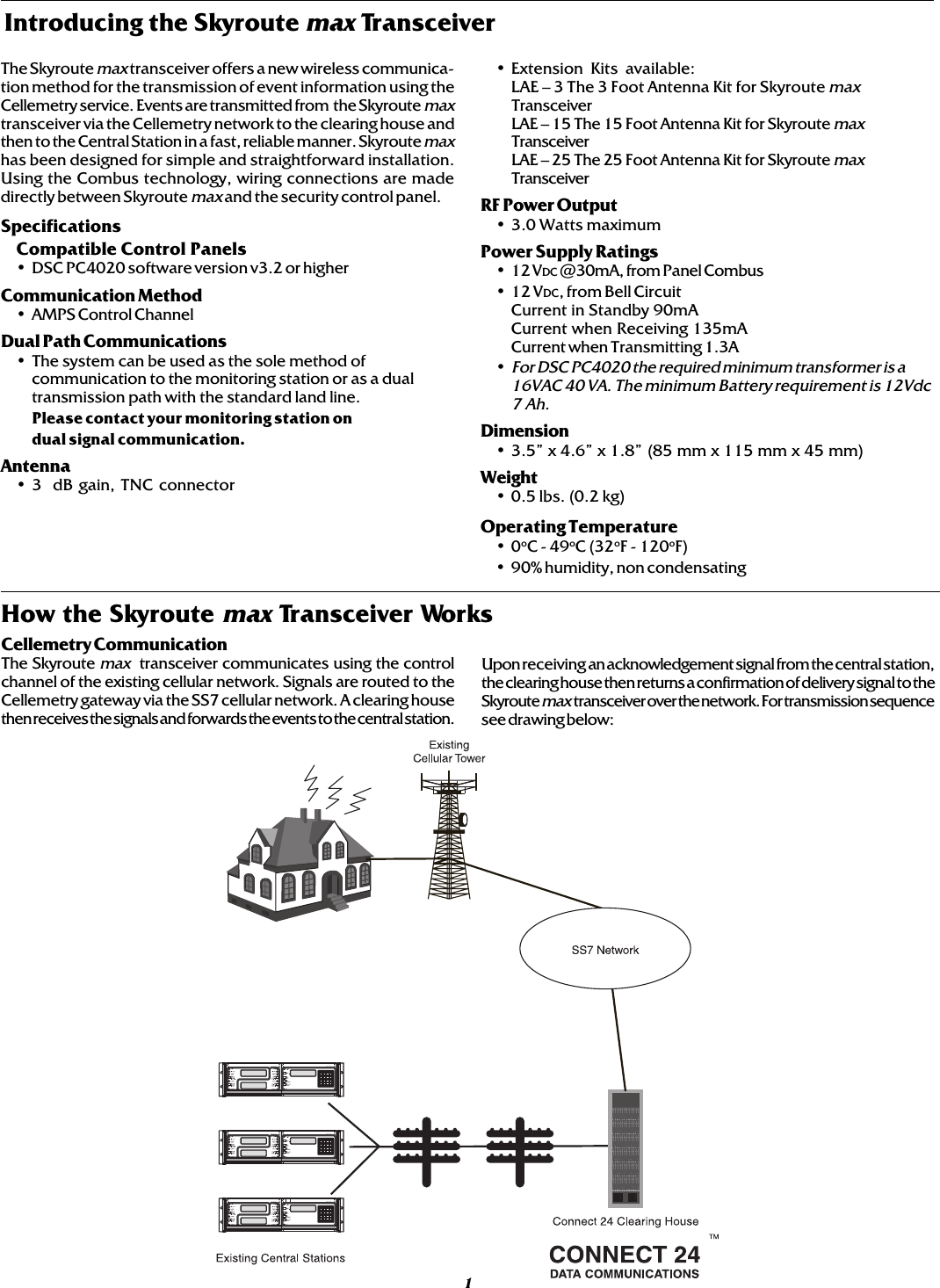
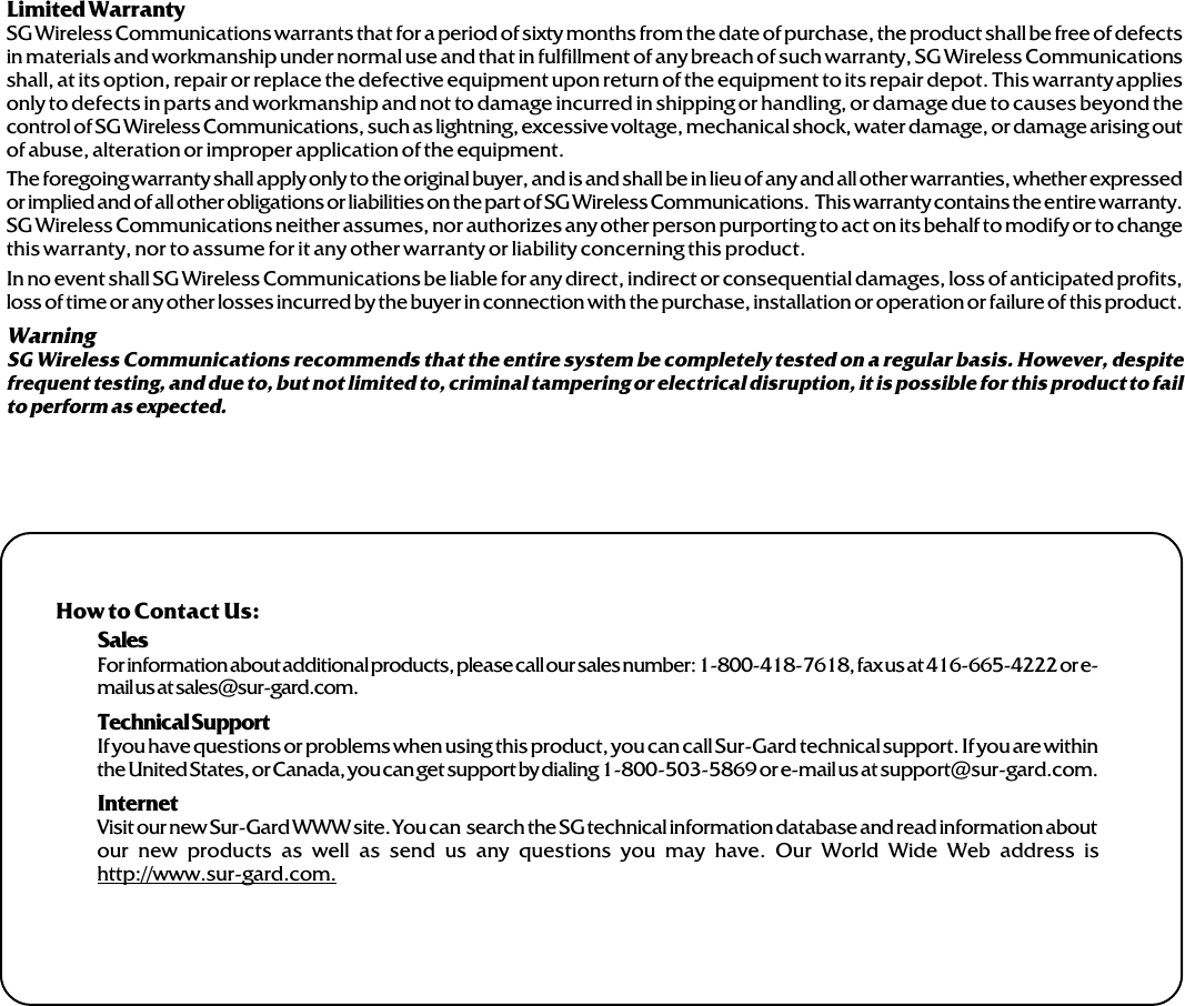
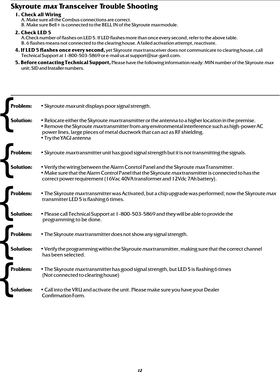
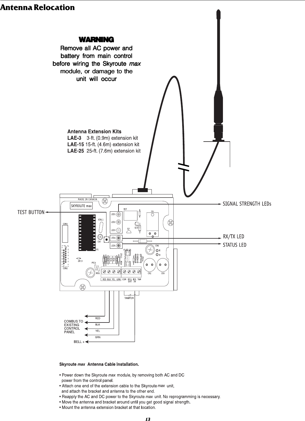
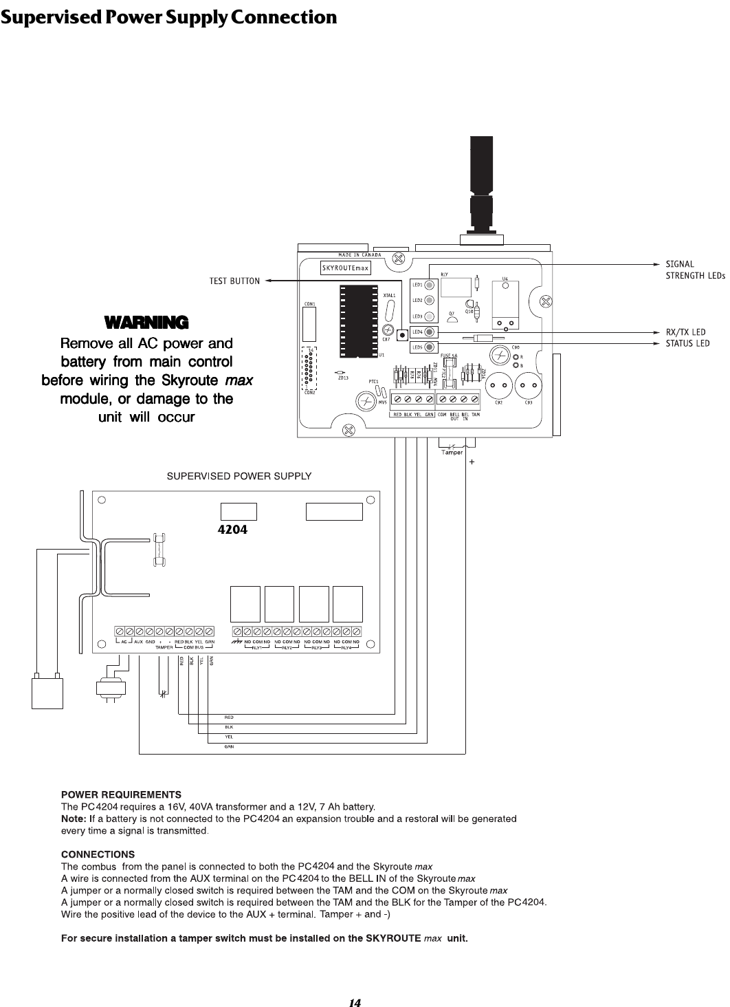
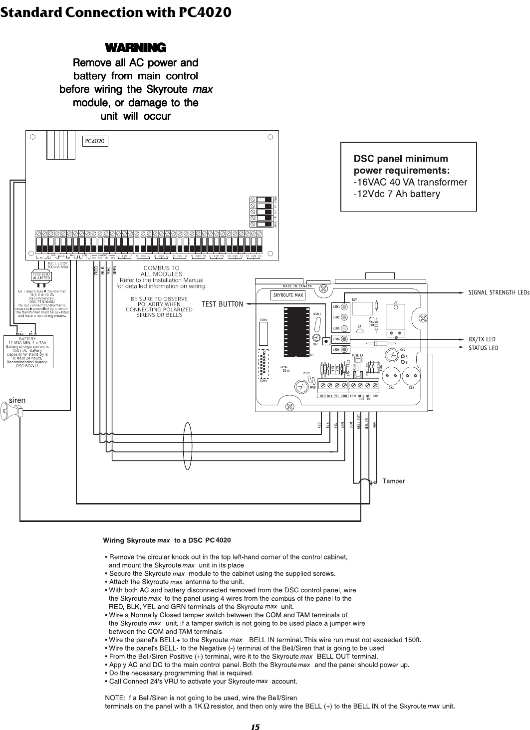
![4Relocating the Skyroute max TransceiverSince the Skyroute max transceiver is a Combus accessory, it is possible to relocate the module up to 1000 feet from the main controlpanel when the panel is not located in a good cellemetry coverage area (a control panel installed in a vault for example). When relocatingthe module, follow theses rules:• Maximum of 1000 feet from the main control. Combus (Red, Black, Yellow, Green) from the panel to the Skyroute maxtransceiver.• A supervised power supply 12V@1A (like the PC4204) must be used (see diagram on page 14).• The power supply (+ positive) is connected to the Skyroute max transceiver (BELL IN) terminal and the power supply(–negative) to the Skyroute max transceiver (COM) terminal.• The cabinet must be installed in a secure location and should have a tamper circuit connected to the Skyroute max (TAM andCOM) terminals.Skyroute max Transceiver Trouble SupervisionThe Skyroute max transceiver automatically monitors its operation and indicates trouble conditions by flashing LED5 on the circuitboard. LED5 normally flashes once every 2 seconds when the Skyroute max transceiver is on stand-by (ready to transmit) mode. Troublesare indicated when LED5 flashes more than once every 2 seconds. Shown below is the number of flashes used to indicate each troublecondition.(1) Radio is operating normally: Skyroute max transceiver is ready to transmit.(2) Radio not powered or not responding: Skyroute max transceiver initialization of Cellemetry modem has failed.(3) Failed self-test: A self-test of the Cellemetry module has failed.(4) Service not available: The Cellemetry modem has failed to register with the cellular network.(5) Failure to communicate: A signal has not been successfully communicated to the central station.(6) Not connected to clearing house: The Skyroute max transceiver has not been activated.(8) Module not enrolled with panel: The Skyroute max transceiver is not addressed by the control panel.Enrolling Skyroute max with PC4020Once all the wiring is complete, you must enroll the module:1. Enter installer’s programming by pressing [*][8][Installer’s Code]2. Scroll to “Module Hardware” and press the [*] key.3. Scroll to “Enroll Module” and press the [*] key.4. Scroll through the different modules until “Alternate Comms” is displayed. Press the [*] key.5. The message “Create Tamper on Desired Unit” will be displayed. To create the required tamper, secure the tamper zone onthe module and then open it. The transition from secure to violated enrolls the module. After this is done, the keypad willdisplay the module number and confirm enrollment “Alternate Comms Mod 01 Enrolled”.For more information regarding module enrollment, see the control panel Installation Manual. Number Function of Flashes of Flashes1 Radio is operating normally2 Radio is not powered, or not responding3 Failed selftest4 Service is not available5 Failure to communicate6 Ready to activate8 Module not enrolled with panelSTEP 2](https://usermanual.wiki/Digital-Security-Controls/SKYROUTE.Users-Manual/User-Guide-128389-Page-8.png)
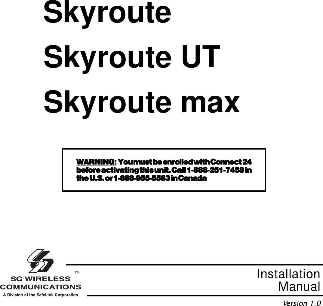
![STEP 3Defaulting the Skyroute maxA default is performed by entering installers programming, [*][8][Installers Code]. Entering section [00][18] will enter the Skyroute maxprogramming, by entering [00] or [22] in subsection [099] the Skyroute max will be defaulted.[00] defaults the unit into full reporting.[22] defaults the unit into generic reporting.Generic ReportingDescriptionThe unit can be set to Full Reporting, or Generic Only. This is to be used on systems that have a telephone line as the primary means of communicationand Skyroute max as a redundant. This option is not meant to make the Skyroute max a back-up unit, but to avoid duplicate signals and large delaysbetween signals at the central station. The only zone signals affected are Burglary. The system has one timer for each partition, the time is 5 minutes.Normal Alarm conditionGeneral reporting will send a generic alarm signal to the central station via the Cellemetry network when a burglary signal is generated. Ifmultiple burglaries are activated, the first will trigger the unit to transmit the associated generic signal. Once the Skyroute max has transmittedthe generic signal it ignores all other burglary alarms on the system for a period of 5 minutes. The Skyroute max unit will ignore any other burglaryalarms that trigger the general transmission during the period the timer is active. If a new alarm of another type (trouble) is triggered then the signalis sent immediately with the corresponding zone number. After the timer has elapsed the unit will then resume standard operation. If a new burglaryalarm occurs after the timer has expired, the sequence restarts. All other events will be transmitted via the unit if the appropriate toggle options areenabled. This is accomplished by defaulting the Skyroute max with a [22] at subsection [099]NoticeA system default must be performed before activation. This is necessary to configure the communication format.NOTE-When the system is defaulted for Generic Reporting the transmission options are as follows. If a signal groupis required, activate the corresponding option.[030] SYSTEM EVENTS (PARTITION 0) TRANSMISSION OPTIONS SECTION ADefault Option ON Option OFFON I_____I Option 1 Alarms DisabledOFF I_____I Option 2 Alarm Restorals DisabledOFF I_____I Option 3 Tampers DisabledOFF I_____I Option 4 Tamper Restorals DisabledOFF I_____I Option 5 Closings DisabledOFF I_____I Option 6 Openings DisabledOFF I_____I Option 7 Maintenance Alarms DisabledOFF I_____I Option 8 Maintenance Alarm Restorals Disabled[031] SYSTEM EVENTS (PARTITION 0) TRANSMISSION OPTIONS SECTION BDefault Option ON Option OFFON I_____I Option 1 Trouble DisabledOFF I_____I Option 2 Trouble Restorals DisabledOFF I_____I Option 3 Bypass DisabledOFF I_____I Option 4 Unbypass DisabledOFF I_____I Option 5 Supervisory Alarm DisabledOFF I_____I Option 6 Supervisory Restoral DisabledOFF I_____I Option 7 Access Control DisabledOFF I_____I Option 8 Miscellaneous Disabled5](https://usermanual.wiki/Digital-Security-Controls/SKYROUTE.Users-Manual/User-Guide-128389-Page-9.png)
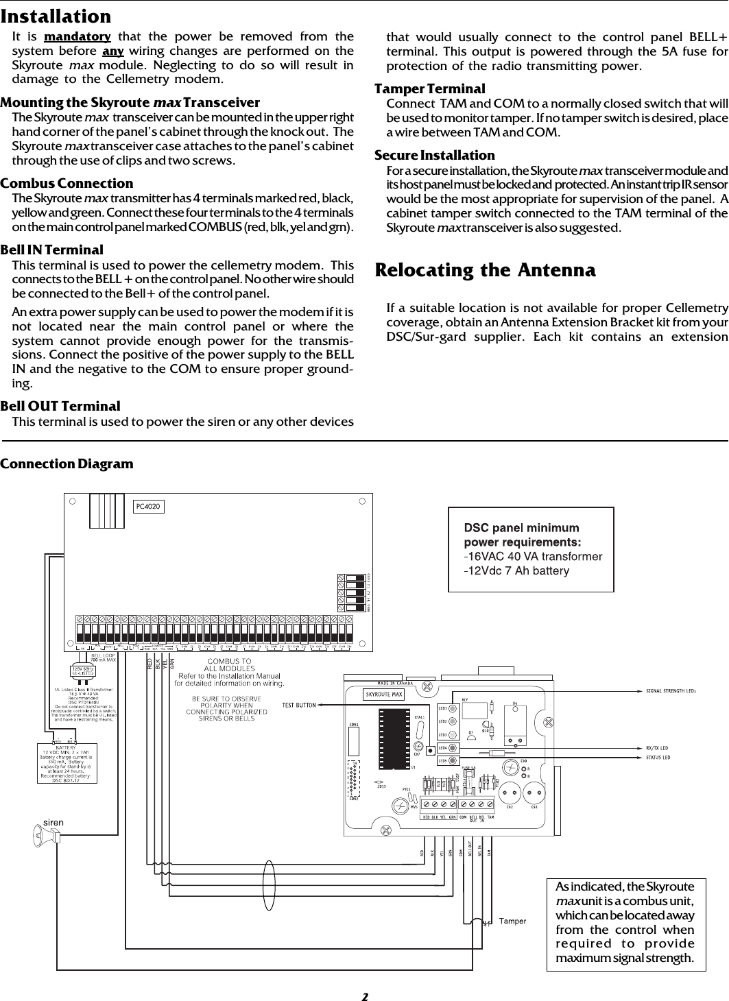
![6Programming SectionsAll programming on the Skyroute max transceiver is done in the installer’s programming mode. Refer to the control panel’s Installation Manualfor instructions on how to enter installer’s programming. From installer’s programming, enter section [00][18] to go to the Skyroute maxprogramming sections.Configuration Options……………………………………Section [006]Channel A enable/disable…………..option [1]This option must be selected when the Cellemetry provider is an “A” side carrier.Channel B enable/disable…………..option[2]This option must be selected when the Cellemetry provider is a “B” side carrier.Home System only enable/disable…option[3]This option must be programmed to ensure that the Skyroute max transceiver is communicating using the proper carrier. Whenselected, the transceiver will only use towers with the same SID (as programmed in section [007]).To Activate the Skyroute max Module in Home Mode1. Select a channel, A or B, in address [006] (Option 1 or 2)2. Program FF into section[099] to restart the unit3. Wait for signal strength.4. Enter in address [007] the Home SID number in hexadecimal format.5. Select Home Mode (Option 3) and deactivate A or B channel in address [006].Note: A restart of the unit is required when changes are made in section [006] . To perform the restart programm FF intosection [099]Skyroute max Transceiver SID (System ID)…………………..Section [007]Please refer to the SID table included with the Skyroute max Module to find out the SID number for your area.Skyroute max Test Time………………………………...………Section [010]Enter in this section the time of the day (24 hour format) that you want the test transmission to be sent.NOTE: Keypad will display ENT HEX. Simply enter value from 0000 to 2359.Test Transmission Day Mask…………………….……….Section [011]Select in this section the day of the week you want the test transmission to be sent.STEP 4Activating the Skyroute max TransceiverBefore activating the Skyroute max transceiver, ensure that the control panel is wired, programmed and operating properly.Make sure that the Skyroute max transmitter is properly connected to the Combus and to the bell positive circuit. When poweris applied to the system, the Skyroute max will perform self-diagnostics for a few seconds, before giving visual feedbackby indicating signal strength on LED1, LED2 or LED3. A complete default of the Skyroute max module should always beperformed before any other programming is done. See Default section for details.Calling Connect 24 Once the Skyroute max transceiver is indicating the signal strength of the network, and the status indicator (LED5) isblinking 6 times (not connected to the clearing house), you are ready to call Connect 24’s Voice Response Unit. Followthe voice prompt and when asked to perform a test, press on SW1 on the Skyroute max transceiver to transmit a testsignal. When transmitting, LED4 blinks once. If the test is successful, the VRU will give you a confirmation and LED5 willthen blink steady every second. Refer to the Connect24 information package for more information on the activationprocess.Phone number for VRU: CANADA: 1-877-759-7688 U.S.: 1-888-251-7554NOTE: The confirmation of a successful test from Connect 24 does not guarantee proper transmission of event to yourcentral station. You must perform normal tests with your monitoring station after activation with Connect 24.Transmitting and ReceivingLED4 on the Skyroute max module will blink once (1) to indicate the Cellular Tower has received the signal. It will blink twice (2)to indicate the Alarm Central Station has received and acknowledged the signal.STEP 5Testing Your Control to the Central StationTest all zones to your Central Station on the telephone line only. After all zone testing, connect Skyroute max and verify communica-tion to Central Station.](https://usermanual.wiki/Digital-Security-Controls/SKYROUTE.Users-Manual/User-Guide-128389-Page-10.png)
![Skyroute max Programming with PC4020[00][18] Skyroute max Programming[006] Skyroute max Configuration OptionsDefault Option ON Option OFFOFF I_____I Option 1 A Channel Selected A Channel Not SelectedON I_____I Option 2 B Channel Selected B Channel Not SelectedOFF I_____I Option 3 Home System Only Not in Home System OperationOFF I_____I Options 4 to 8 For system use do not modify.[007] Home SID NumberDefault0000 I_____I_____I_____I_____I This is the SID (in Hex) of the cellular service that is availableon the current channel.[010] Skyroute max Test TimeDefault9999 I_____I_____I_____I_____I 0000-2359 (in 24 hour time)NOTE: Keypad will display ENT HEX. Simply enter valuefrom 0000 to 2359.[011] Test Transmission Day MaskDefault Option ON Option OFFOFF I_____I Option 1 Test on Sunday DisabledOFF I_____I Option 2 Test on Monday DisabledOFF I_____I Option 3 Test on Tuesday DisabledOFF I_____I Option 4 Test on Wednesday DisabledOFF I_____I Option 5 Test on Thursday DisabledOFF I_____I Option 6 Test on Friday DisabledOFF I_____I Option 7 Test on Saturday DisabledOFF I_____I Option 8 For Future Use[013] Skyroute max Test RatesDefaultOFF I_____I Option 1 For Future UseOFF I_____I Option 2 Daily Test DisabledON I_____I Option 3 Weekly Test DisabledOFF I_____I Options 4 to 8 For Future Use7](https://usermanual.wiki/Digital-Security-Controls/SKYROUTE.Users-Manual/User-Guide-128389-Page-11.png)
![Sections [030] to [047] will disable groups of reporting codes.[030] System Event (Partition 0) Transmission Options Section ADefault Option ON Option OFFON I_____I Option 1 Alarms DisabledOFF I_____I Option 2 Alarm Restorals DisabledOFF I_____I Option 3 Tampers DisabledOFF I_____I Option 4 Tamper Restorals DisabledOFF I_____I Option 5 Closings DisabledON I_____I Option 6 Openings DisabledON I_____I Option 7 Maintenance Alarms DisabledON I_____I Option 8 Maintenance Alarm Restorals Disabled[031] System Events (Partition 0) Transmission Options Section BDefault Option ON Option OFFON I_____I Option 1 Trouble DisabledON I_____I Option 2 Trouble Restorals DisabledOFF I_____I Option 3 Bypass DisabledOFF I_____I Option 4 Unbypass DisabledOFF I_____I Option 5 Supervisory Alarm DisabledOFF I_____I Option 6 Supervisory Restoral DisabledOFF I_____I Option 7 Access Control DisabledOFF I_____I Option 8 Miscellaneous Disabled[032] Partition 1 Transmission Options Section ADefault Option ON Option OFFON I_____I Option 1 Alarms DisabledOFF I_____I Option 2 Alarm Restorals DisabledOFF I_____I Option 3 Tampers DisabledOFF I_____I Option 4 Tamper Restorals DisabledOFF I_____I Option 5 Closings DisabledON I_____I Option 6 Openings DisabledON I_____I Option 7 Maintenance Alarms DisabledON I_____I Option 8 Maintenance Alarm Restorals Disabled[033] Partition 1 Transmission Options Section BDefault Option ON Option OFFON I_____I Option 1 Trouble DisabledON I_____I Option 2 Trouble Restorals DisabledOFF I_____I Option 3 Bypass DisabledOFF I_____I Option 4 Unbypass DisabledOFF I_____I Option 5 Supervisory Alarm DisabledOFF I_____I Option 6 Supervisory Restoral DisabledOFF I_____I Option 7 Access Control DisabledOFF I_____I Option 8 Miscellaneous Disabled[034] Partition 2 Transmission Options Section ADefault Option ON Option OFFON I_____I Option 1 Alarms DisabledOFF I_____I Option 2 Alarm Restorals DisabledOFF I_____I Option 3 Tampers DisabledOFF I_____I Option 4 Tamper Restorals DisabledOFF I_____I Option 5 Closings DisabledON I_____I Option 6 Openings DisabledON I_____I Option 7 Maintenance Alarms DisabledON I_____I Option 8 Maintenance Alarm Restorals Disabled8](https://usermanual.wiki/Digital-Security-Controls/SKYROUTE.Users-Manual/User-Guide-128389-Page-12.png)
![[035] Partition 2 Transmission Options Section BDefault Option ON Option OFFON I_____I Option 1 Trouble DisabledON I_____I Option 2 Trouble Restorals DisabledOFF I_____I Option 3 Bypass DisabledOFF I_____I Option 4 Unbypass DisabledOFF I_____I Option 5 Supervisory Alarm DisabledOFF I_____I Option 6 Supervisory Restoral DisabledOFF I_____I Option 7 Access Control DisabledOFF I_____I Option 8 Miscellaneous Disabled[036] Partition 3 Transmission Options Section ADefault Option ON Option OFFON I_____I Option 1 Alarms DisabledOFF I_____I Option 2 Alarm Restorals DisabledOFF I_____I Option 3 Tampers DisabledOFF I_____I Option 4 Tamper Restorals DisabledOFF I_____I Option 5 Closings DisabledON I_____I Option 6 Openings DisabledON I_____I Option 7 Maintenance Alarms DisabledON I_____I Option 8 Maintenance Alarm Restorals Disabled[037] Partition 3 Transmission Options Section BDefault Option ON Option OFFON I_____I Option 1 Trouble DisabledON I_____I Option 2 Trouble Restorals DisabledOFF I_____I Option 3 Bypass DisabledOFF I_____I Option 4 Unbypass DisabledOFF I_____I Option 5 Supervisory Alarm DisabledOFF I_____I Option 6 Supervisory Restoral DisabledOFF I_____I Option 7 Access Control DisabledOFF I_____I Option 8 Miscellaneous Disabled[038] Partition 4 Transmission Options Section ADefault Option ON Option OFFON I_____I Option 1 Alarms DisabledOFF I_____I Option 2 Alarm Restorals DisabledOFF I_____I Option 3 Tampers DisabledOFF I_____I Option 4 Tamper Restorals DisabledOFF I_____I Option 5 Closings DisabledON I_____I Option 6 Openings DisabledON I_____I Option 7 Maintenance Alarms DisabledON I_____I Option 8 Maintenance Alarm Restorals Disabled[039] Partition 4 Transmission Options Section BDefault Option ON Option OFFON I_____I Option 1 Trouble DisabledON I_____I Option 2 Trouble Restorals DisabledOFF I_____I Option 3 Bypass DisabledOFF I_____I Option 4 Unbypass DisabledOFF I_____I Option 5 Supervisory Alarm DisabledOFF I_____I Option 6 Supervisory Restoral DisabledOFF I_____I Option 7 Access Control DisabledOFF I_____I Option 8 Miscellaneous Disabled9](https://usermanual.wiki/Digital-Security-Controls/SKYROUTE.Users-Manual/User-Guide-128389-Page-13.png)
![[040] Partition 5 Transmission Options Section ADefault Option ON Option OFFON I_____I Option 1 Alarms DisabledOFF I_____I Option 2 Alarm Restorals DisabledOFF I_____I Option 3 Tampers DisabledOFF I_____I Option 4 Tamper Restorals DisabledOFF I_____I Option 5 Closings DisabledON I_____I Option 6 Openings DisabledON I_____I Option 7 Maintenance Alarms DisabledON I_____I Option 8 Maintenance Alarm Restorals Disabled[041] Partition 5 Transmission Options Section BDefault Option ON Option OFFON I_____I Option 1 Trouble DisabledON I_____I Option 2 Trouble Restorals DisabledOFF I_____I Option 3 Bypass DisabledOFF I_____I Option 4 Unbypass DisabledOFF I_____I Option 5 Supervisory Alarm DisabledOFF I_____I Option 6 Supervisory Restoral DisabledOFF I_____I Option 7 Access Control DisabledOFF I_____I Option 8 Miscellaneous Disabled[042] Partition 6 Transmission Options Section ADefault Option ON Option OFFON I_____I Option 1 Alarms DisabledOFF I_____I Option 2 Alarm Restorals DisabledOFF I_____I Option 3 Tampers DisabledOFF I_____I Option 4 Tamper Restorals DisabledOFF I_____I Option 5 Closings DisabledON I_____I Option 6 Openings DisabledON I_____I Option 7 Maintenance Alarms DisabledON I_____I Option 8 Maintenance Alarm Restorals Disabled[043] Partition 6 Transmission Options Section BDefault Option ON Option OFFON I_____I Option 1 Trouble DisabledON I_____I Option 2 Trouble Restorals DisabledOFF I_____I Option 3 Bypass DisabledOFF I_____I Option 4 Unbypass DisabledOFF I_____I Option 5 Supervisory Alarm DisabledOFF I_____I Option 6 Supervisory Restoral DisabledOFF I_____I Option 7 Access Control DisabledOFF I_____I Option 8 Miscellaneous Disabled[044] Partition 7 Transmission Options Section ADefault Option ON Option OFFON I_____I Option 1 Alarms DisabledOFF I_____I Option 2 Alarm Restorals DisabledOFF I_____I Option 3 Tampers DisabledOFF I_____I Option 4 Tamper Restorals DisabledOFF I_____I Option 5 Closings DisabledON I_____I Option 6 Openings DisabledON I_____I Option 7 Maintenance Alarms DisabledON I_____I Option 8 Maintenance Alarm Restorals Disabled10](https://usermanual.wiki/Digital-Security-Controls/SKYROUTE.Users-Manual/User-Guide-128389-Page-14.png)
![[045] Partition 7 Transmission Options Section BDefault Option ON Option OFFON I_____I Option 1 Trouble DisabledON I_____I Option 2 Trouble Restorals DisabledOFF I_____I Option 3 Bypass DisabledOFF I_____I Option 4 Unbypass DisabledOFF I_____I Option 5 Supervisory Alarm DisabledOFF I_____I Option 6 Supervisory Restoral DisabledOFF I_____I Option 7 Access Control DisabledOFF I_____I Option 8 Miscellaneous Disabled[046] Partition 8 Transmission Options Section ADefault Option ON Option OFFON I_____I Option 1 Alarms DisabledOFF I_____I Option 2 Alarm Restorals DisabledOFF I_____I Option 3 Tampers DisabledOFF I_____I Option 4 Tamper Restorals DisabledOFF I_____I Option 5 Closings DisabledON I_____I Option 6 Openings DisabledON I_____I Option 7 Maintenance Alarms DisabledON I_____I Option 8 Maintenance Alarm Restorals Disabled[047] Partition 8 Transmission Options Section BDefault Option ON Option OFFON I_____I Option 1 Trouble DisabledON I_____I Option 2 Trouble Restorals DisabledOFF I_____I Option 3 Bypass DisabledOFF I_____I Option 4 Unbypass DisabledOFF I_____I Option 5 Supervisory Alarm DisabledOFF I_____I Option 6 Supervisory Restoral DisabledOFF I_____I Option 7 Access Control DisabledOFF I_____I Option 8 Miscellaneous DisabledNOTE: Default must be performed before activating the Skyroute max[099] Section [099] is for software defaulting of the Skyroute maxDefault63 I_____I____I*Entering 00 will cause a software default of the Skyroute max*Entering 22 will cause a software default of the Skyroute max to Generic reporting*Entering FF will cause restart of the Skyroute max transceiver11](https://usermanual.wiki/Digital-Security-Controls/SKYROUTE.Users-Manual/User-Guide-128389-Page-15.png)
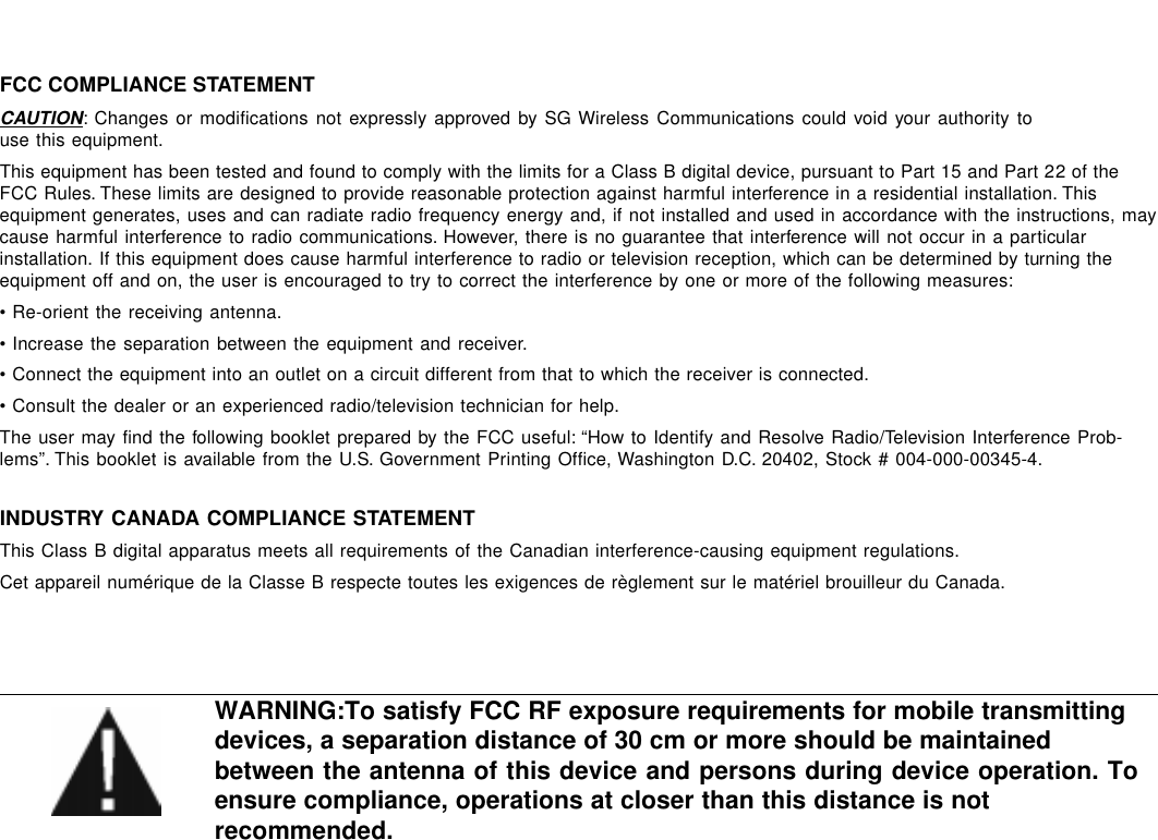
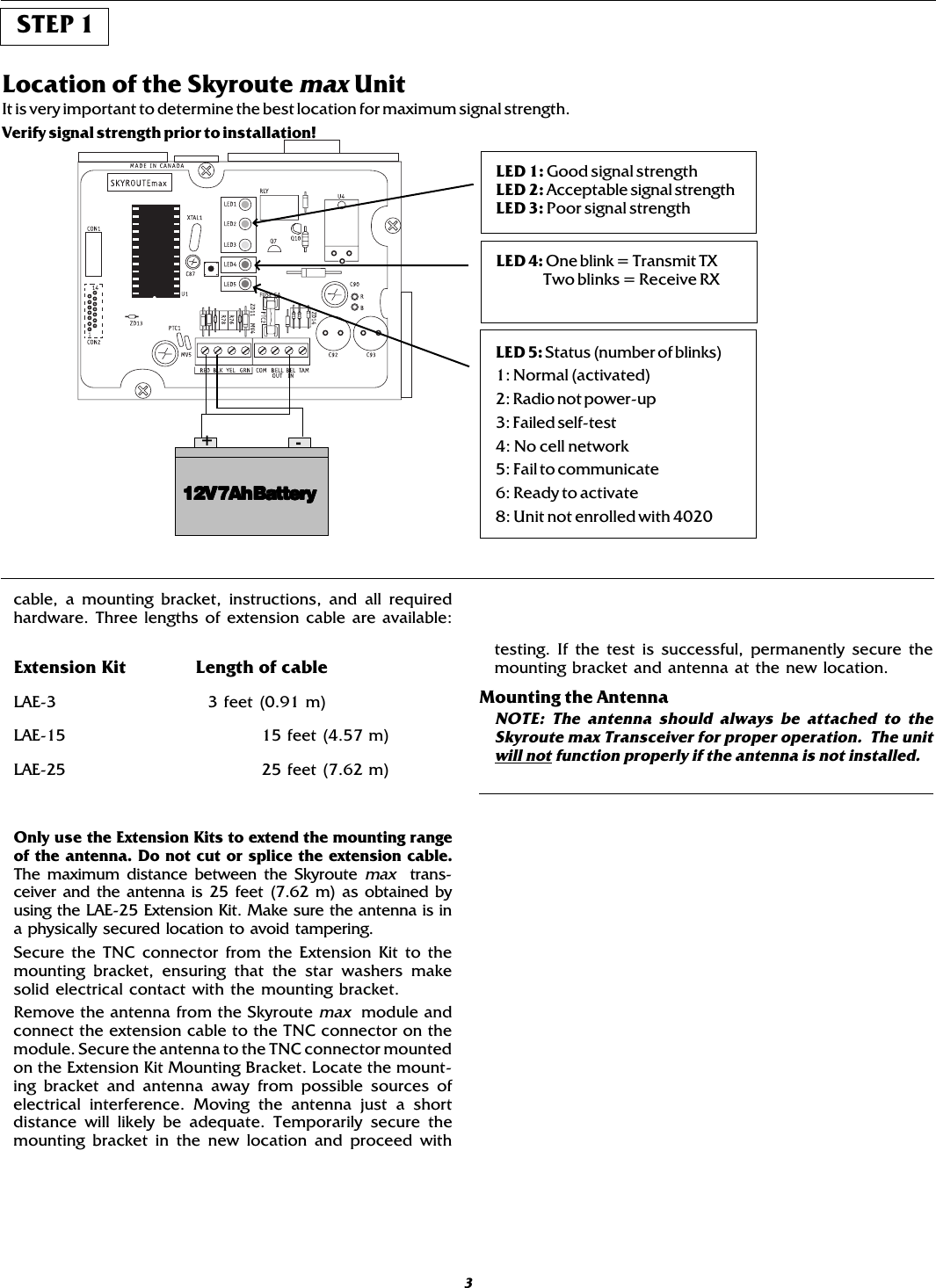
![Appendix A - Reporting codes for SIA and Contact ID17* A/R = alarms/restorals; O/C = openings/closings; O = other**PPP = partition number; UUU = user number (user 1000=999); ZZZ = zone numberedoCgnitropeR DItcatnoC peRotuAAIS **sedoC edoCgnitropeR DItcatnoC peRotuAAIS **sedoCsmralAenoZ"sedoCgnitropeRenoZ"BxidneppAeesgnisolCnoititraP654PPP-GCslarotseRenoZ sgninepO104UUU-POrepmaT/elbuorTenoZ 0001-921gninepO104UUU-PO.tseRrepmaT/elbuorTenoZ gninepOlaicepS104000-POtluaFenoZ citamotuA )deludehcS( gninepO 304000-AO.tseRtluaFenoZ gninepOnoititraP204PPP-GO.tseR/mralAyeK]F[011000-HF/000-AF yrettaB .tseR/elbuorT 203000-RY/000-TY.tseR/mralAyeK]A[001000-HM/000-AM eniLCA .tseR/elbuorT 103999-RA/999-TA.tseR/mralAyeK]P[021000-HP/000-AP lleBlenaP .tseR/elbuorT 123999-HY/999-AYmralAsseruD221000-AH yrellixuAlenaP .tseR/elbuorT 213999-QY/999-PYmralaretfagninepO854000-RO submoC .tseR/elbuorT 003999-JU/999-TUgnisolCtneceR954000-RC.tseR/eruliaFMLT153100-RL/100-TL)edoCeciloP(enoZssorC mralA 931000-VB 2eniLMLT .tseR/eruliaF 153200-RL/200-TL.tser/mralAdecroFrooD324ZZZ-RD/ZZZ-FDlarotseRCTF453000-KYgnolootneporooD .tser/mrala 624ZZZ-HD/ZZZ-NDlluFraeNreffuB226000-LJ.tser/repmatmetsyslareneG731000-RT/000-ATtsetmetsySresU106000-XRtuokcoldapyeK164000-AJtseTcidoireP206000-PR.tser/mralaeriw-2011999-HF/999-AFtseTSKNIL306000-XT.tser/mralawolfretaW011899-HS/899-AS.tseR/tluaFdnuorG041000-RU/000-SU.tser/elbuorteriw-2373999-JF/999-TFnidaeLSLD726000-BR.tser/elbuortwolfretaW002899-JS/899-TStuodaeLSLD826000-SRnigebtseteriF406000-IFnIdaeLrellatsnI854000-BLdnetseteriF406000-KFtuOdaeLrellatsnI854000-SLssapybnu.ssapyberiF175ZZZ-UF/ZZZ-BFycneuqnileDgnisolC456000-DCsgnisolC104UUU-LCtseTklaW delbanE706000-ST0001-921gnisolC104UUU-LCtseTklaW delbasiD 706000-ETgnisolClaitraP054000-WC metsySlareneG .tseR/elbuorT 003000-XY)deludehcS(citamotuA gnisolC 304000-AC woleciveDlareneG .tseR/yrettaB 203 ZZZ-RX/TX 409-109-RX/TX 639-129-RX/TXnoitallecnaCmrAotuA504000-EC mmoCeludoMneG .tseR/tluaF 033000-RE/000-TE](https://usermanual.wiki/Digital-Security-Controls/SKYROUTE.Users-Manual/User-Guide-128389-Page-21.png)